1
ASTRONOMICAL OBSERVATORY OF VILNIUS UNIVERSITY
HIGH-SPED THREE-CHANNEL PHOTOMETER
HSTCP
USER'S GUIDE
(To Mol_etai version)
Edited by
E. G. Meistas
Vilnius, 2002
3
TABLE OF CONTENTS
PART A PHOTOMETER DESCRIPTION
1. INTRODUCTION : : : : : : : : : : : : : : : : : : : : : : : : : : : : : : : : : : : : : : : : : : : : : : : : : : 3
2. SHORT INTRODUCING TO THE PHOTOMETER : : : : : : : : : : : : : : : : 3
PART USER'S MANUAL
3. BEFORE THE OBSERVATIONS : : : : : : : : : : : : : : : : : : : : : : : : : : : : : : : : : : : 8
3.0. Controlling the instrumentation : : : : : : : : : : : : : : : : : : : : : : : : : : : : : : : : : : : : 8
3.1. Starting the system : : : : : : : : : : : : : : : : : : : : : : : : : : : : : : : : : : : : : : : : : : : : : : : : 8
3.2. Initialization : : : : : : : : : : : : : : : : : : : : : : : : : : : : : : : : : : : : : : : : : : : : : : : : : : : : : : 9
3.3. Positioning of the Ch1 and Ch2 stars and checking the Ch3 : : : : : : : : 8
3.4. Setting apertures, centering Ch1 and Ch2 stars, checking Ch3 : : : : : 11
3.5. Continuing "Auriga" program settings and data recording : : : : : : : : : 15
4. AT THE OBSERVATIONS : : : : : : : : : : : : : : : : : : : : : : : : : : : : : : : : : : : : : : : : : 16
4.1. Continuous time series observations of the variable : : : : : : : : : : : : : : : : 17
5. AT THE END OF OBSERVATIONS : : : : : : : : : : : : : : : : : : : : : : : : : : : : : : : 18
6. RECOMMENDATIONS : : : : : : : : : : : : : : : : : : : : : : : : : : : : : : : : : : : : : : : : : : : 18
APPENDIX 1: Position values : : : : : : : : : : : : : : : : : : : : : : : : : : : : : : : : : : : : : : : : 20
APPENDIX 2: Abbreviations and markings in the pictures : : : : : : : : : : : : 22
APPENDIX 3: Technical specications of the HSTCP : : : : : : : : : : : : : : : : : 23
4
PART A
PHOTOMETER DESCRIPTION
1. INTRODUCTION
General purpose high-speed three-channel photometer (HSTCP) is designed
for the time series photometry of variable stars as well as for the multicolor
photometry using UBVR and Vilnius photometric systems. Other photometric
systems as Stromgren or others could be used in the photometer. The photometer conforms to main requirements of observations according to "Whole
Earth Telescope" program as well as to ones of the photometry of variable stars
as well as according to usual observational programs of multicolor photometry.
Abbreviations and markings used in the pictures are given at the end of the
paper in the Appendix 2, and technical data of the HSTCP - in Appendix 3.
This photometer and the software was made at Vilnius University in Laboratory
of astrophotometry of Astronomical Observatory in fruitful collaboration with
people from Institute of Theoretical physics and Astronomy: R. Kalytis was
the project manager, R. Skipitis - the main designer of mechanical and optical
parts and many parts were machined by him too, E. Siauciunas, developed main
electronics and R. Janulis created the software.
2. SHORT INTRODUCING TO THE PHOTOMETER
The photometer HSTCP consists of ve main parts: 1) optical-mechanical
module; 2) box of electronics; 3) =24 V power supply; 4) manual control handpaddle and 5) GPS receiver. There are only few functions possible to access
before the special software (AURIGA or CORVUS) are activated. Most of the
adjustments are possible to make with the step-motors via the handpaddle only,
which is active only when the software is loaded and initialization of the photometer is completed.
Optical-mechanical module of the HSTCP contains all necessary optical
and mechanical controls to nd the target and the comparison stars, to center
their images in the apertures, and to apply the light of both stars and of the sky
background to the photocathodes of the appropriate photomultipliers (PMTs).
The ange of the photometer attachment to the telescope contains very
important mechanical device - the rotational bearing with the position limb RL
(see this and the next features in Figs. 2, 4-6). It makes possible to use this
photometer even with the telescopes which do not have their own positioning
bearing. The handle RH is for the ne rotation of the bearing and handle RF
is to stop the bearing in the required position for the ne rotation with the RH,
or to release the bearing for free raw rotation by hand.
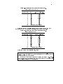
The main principle of the optical design is shown in the Fig.1. When telescope is pointed to the target star and it is centered in the aperture, photometer
optical axis is on the optical axis of the telescope. To see this star in the main
viewnder (FL in Figs 2, 4-5) eld center (on its croshair), this radially movable viewnder position pointer RP must be at "0" on the position ruler R1
(see them in Fig.5). The comparison (Ch2) star may be selected in the hatched
5
Fig. 1. The principle of the HSTCP optical design.
area, which may be searched moving the main viewnder radially from 26 mm
position till the 50 mm position of the ruler R1 (this path is marked with thick
arrow "A" in Fig.1) and the same time rotating all photometer around its optical axis using above mentioned rotator. And Ch2 optical axis can be positioned
on the selected star beam rotating all Ch2 housing around its 12 mm oset axis
to the same value on its limb as pointer RP showed on the main viewnder
ruler R1 This possibility is showed with thick arrow "B" in Fig.1.
But Ch3 - the sky background channel is hard-positioned in the same housing together with the Ch1. Because their distance is not changeable, after Ch1
and Ch2 positions are xed, Ch3 is looking to some accidental area of the sky,
which may be with some "contamination". To make possible to escape from
some problematic place, it is made possible rotate a bit all Ch1-3 around the
Ch1 optical axis, the same time deviating Ch3 from the previous area, and selecting some more acceptable Ch3 position (this feature is demonstrated with
the arrow "C" in Fig.1).
The box of the electronics could be seen at the left side of the Fig.4 (marked
PB in Fig. 4). It contains all electric circuitry necessary for the power supply
to all units of the photometer, for their control and for the data acquisition. It
includes microprocessor and computer interface, step motor drivers, electronics
of cooling system, low and high voltage power supplies.
=24 V power supply is standard AC/DC converter (converting 220 V to
=24 V) operating as a main power supply of the photometer.
6
In the pictures (Figs. 2, 4-8) one can introduce to all controls of the photometer: starting from the rotator bearing, through the eld lens (the main
viewnder) and aperture microscopes, and nishing with the signal outputs at
the ampliers-discriminators.
It is very important even at the rst introduction already to locate the
handles SH1 and SH2 (shown in Fig.7) of the shutters on both Ch1-3 and Ch2
housings. These shutters must be closed at all adjustments of the telescope and
of the photometer units, and must be opened only when the photometer is ready
for the safe measurements.
The special attention must be paid to the three housings of the ampliersdiscriminators of this photometer A1, A2, A3. They are most prominent and
not-too-strong mechanically units and they may be damaged by the accidental
banging even with the comparatively modest force.
There is separate handpaddle ( Fig.9), which may be used for the manual
control of the photometer features, when observer is at the telescope.
GPS receiver is the standard receiver of signals from the Global Positioning
System (GPS) and is providing standard information coming from GPS, including one PPP (pulse per second) signals for synchronization of the photometer
to the Universal Time (UT).
In enlarged ange-close-pictures of the photometer (Figs. 4-7) are shown
more clearly above mentioned and some other important controls to be used at
the observations. They will be addressed when it will be needed in this user
guide at the description of the observers actions at the positioning of the stars
into the appropriate channels and at the observations.
The main measuring channel (rst channel { Ch1) of the photometer is
designed for the light measurement of a target star.
The second channel (Ch2) is used for the light measurement of a comparison
star and can be moved and positioned in the ring eld around the rst channel.
The third channel (Ch3) is designated for the light measurement of the
sky background and it is in one mechanical-optical unit with the rst channel.
It is located at the constant distance (with the possibility of small rotational
deviations) from the rst channel.
Light beams of all three channels can be observed with the large eld eyepiece unit FL - the main viewnder of the photometer. All these beems are
passing 130 mm diameter central hole of rotational bearing. These light beams
might directed either to this movable large eld viewnder (when the big ipmirror FM is "IN" or to two diaphragm wheels (to apertures of all three channels) when the ip mirror is "OUT".
Movable large eld eyepiece could be moved linearly into any position till
the distance of 50 mm perpendicularly to the main axis of the telescope. Combining this movement and rotation of all photometer around the optical axis
of the telescope it is possible to survey the sky eld around the target star
(the rst channel) and to select a comparison star for the second channel in a
ring-shape-eld accessible for the Ch2 unit.
When the ip mirror is withdrawn, the light beams of all three channels is
directed to the diaphragm wheels. The focal plane of the telescope lies at the
plane of two motorized diaphragm wheels from which a eld from 0.4 to 8.0 mm
can be selected. Though there are three channels in the photometer, but there
7
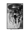
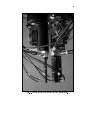
Fig. 2. The main picture of the photometer
8
are two diaphragm wheels only. The rst one contains apertures placed in pairs
for both Ch1 and Ch3, because these channel units are too close to each other
to have two separate wheels, and for the movable Ch2 the second { separate
diaphragm wheel is used.
After passing the apertures, the light beams of the stars are directed to
the Fabry lenses of the channel units if the prism of the aperture microscope
M1-3 is not inserted. When the prism is "IN", the star light is directed to
the aperture microscope. For the Ch1 and Ch3 one motorized movable prism is
used. It could be set in three positions: " Ch1". "Ch3." and "withdrawn".
When the star is centered in the selected aperture, above mentioned prism
is moved to the "OUT" position, and the star light beam passes to Fabry lens.
After the Fabry lens star light in each channel unit is transformed into parallel
light beam, which passes lters placed in two lter wheels and, at the end, as
the images of the primary mirror are projected onto the photocathodes of the
photomultiplier of the each channel.
PART B
(USER'S MANUAL)
3. BEFORE THE OBSERVATIONS
3.0. Controlling the instrumentation
It is recommended that the dark counts in all three channels as well as light
counts from standard sources would be checked before observations. The sense
of this checking is that observer must be sure that dark counts and sensitivity
of the channels are the same or similar to the ones received in previous days. If
the large dierence in those values are observed, the reason of those dierences
must be found and xed. Test of long-time (several hours) stability of both:
dark and light signals should be measured, especially after instrument was not
used for some time, after transportation in hard conditions, etc.
3.1. Starting the system
First of all! { it must be checked whether both shutters of Ch1-3 and Ch2
(SH1 and SH2 in Fig.8) are closed. At the rst exercises, when studying the
photometer The Low Voltage (24 V in Fig.4) power must be "ON", but High
Voltage (HV in Fig.4) must be "OFF".
On the contrary, at the normal observations High Voltage (HV) stays "ON"
all the time: day and night, usually. In that case the handling of the photometer
must be especially careful, looking that the photomultipliers would not get too
bright illumination - they can be totally damaged.
Aperture wheels, lter wheels and reecting prisms of both microscopes
are "motorized\, equipped with the step motors (ve of them). It is possible
to handle them only via operational computer or via the handpaddle when the
data acquisition program AURIGA (for WET style time-series observations), or
9
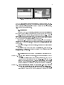
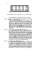
Fig. 3. Auriga's starting panel and submenu "Photometer".
CORVUS (for multicolor observations) is launched, working properly, and photometer is initialized. Except that, GPS unit must be launched too - otherwise
system will use computer initial time (it is OK if exact time is not necessary,
e.g. at photometer investigations).
3.2. Initialization
After the AURIGA.EXE is started, all actions of photometer initialization
in the opened window must be performed via the menu and submenu commands.
First - click menu "Photometer", then submenu "Link" (Fig.3). After the
linear window is on, check if everything { the port number, IRQ number, and
communication speed are correct in it. Then give the command to link computer
to the photometer and initialize it clicking button "Link".
If everything - the cables and powering is correct, then the progress bar
appears and after it is lled in, if everything went smoothly, the software gives
message "READY" in the window. To accept and to nish initialization click
"OK" button.
After these actions, photometer is "alive", all systems and illuminations
are working.
If something would went wrong in time of initialization, then: "Photometer" { "Link" { "Unlink" would return the system to the starting point and
initialization may be restarted.
3.3. Positioning of the Ch1 and Ch2 stars and checking the Ch3
ACTION 1 - Set the eld mirror (FM in Fig.4) of the photometer to "IN"
position.
After that all star beams in the eld are reected 90 and may be
watched via the main viewnder (FL in Figs.1, 4-7), which can be relocated in the eld in two ways | linearly with the Field Lens Position
handle FLP and circularly, rotating all photometer around the optical
axis of the telescope when the stop handle of the rotator RF is released.
ACTION 2 - After the telescope is pointed to the program-star (Ch1 star) its
image must be centered in the viewnder ( FL in Figs.1, 4-7).
But before that the ruler pointer RP at the viewnder croshair position ruler R1 must be set to the "0" value; that means that the center
10
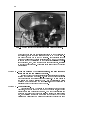
Fig. 4. The top part of the photometer (the Field Mirror Handle side).
of the viewnder eld and its croshair is pointed to the optical axis of
the telescope, and if the eld mirror FM would be "OUT" the star image would be on its way to the Ch1 aperture. If the croshair is badly
or too much illuminated, there is potentiometer CL (Fig.4), to adjust it.
It is good idea at the beginning of the observations to adjust the telescope guider so, that, when the star image is on its croshair, it is close
to the viewnder center too. This action saves lots of time at the future
observations;
ACTION 3 - When the program (Ch1) star is centered, the next step is to
locate and set the comparison (Ch2) star.
It could be done when observer is searching the suitable star manually,
rotating the handle (FLP in Figs.2, 4-7) and the same time rotating all
photometer around the optical axis of the telescope. The stop handle of
the rotator RF must be released at that. But, if precalculated values
of ruler R1 and rotator limb RL are available, then much less time is
necessary to set the viewnder to the Ch2 star.
ACTION 4 - Ch2 star setting.
After action "3" the Ch2 star is on the crosshair of the main eld
viewnder, but not on its way to the Ch2 of the photometer, if the eld
mirror (FM) would be switched to "OFF". To make the nal setting one
must read the value of the viewnder ruler R1 scale at the ruler pointer
RP, and releasing the stopper L1F rotate the handle of the Ch2 unit
position L1H till the limb L1 pointer LP will point to exactly the same
11
Fig. 5. The top part of the photometer (the Viewnder side).
value as it was read on the ruler R1. After this action the Ch1 and Ch2
stars are set into their positions, and it is time to go to the next step - to
set/center the images of the stars into appropriate apertures of Ch1 and
Ch2.
It is completed job from here with the eld mirror "IN". From now it must
be made "OFF" with the handle FM (Fig. 4), to let the beams of the stars to
the apertures.
3.4. Setting the apertures, centering Ch1 and Ch2 stars in them,
and checking Ch3
Since the data acquisition program is working and photometer initialization
is completed, it is possible to continue setting of the photometer - the aperture
sizes, centering stars into them, and setting of the lters. The next few actions
must be performed manually via the handpaddle (Fig.8), and the rst step is to
take control from the computer to the handpaddle - to press button "ON" of it.
If interface is prepared to work with the handpaddle, indicators at "MOTOR"
and "POSITION" will show some numbers in their windows. If interface is not
ready for some reason (e.g. it might be still busy with some measurements)
then both indicators will show "|" (dashes).
12
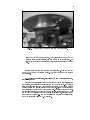
Fig. 6. The middle part of the photometer (the Viewnder position controls).
Fig. 8. The handpaddle for manual adjustments at the photometer.
In that case it is possible to force the interface to give priority to the
handpaddle pressing "OFF", and few seconds later "ON". This will force
interface to stop what it was doing and after some time (which it might use
e.g., to save the data of the activity) and it will show some numbers in above
mentioned indicators, announcing that it is ready for the manual commands.
Then, with the handpaddle buttons "{" or "+" the needed step motor number
could be set (numbers from 1 to 5 in the indicator), and after that, when the right
button "POSITION" is pressed, with the same "{" or "+" buttons necessary
position of the unit to which this engine is attached can be selected.
In Fig.9 are shown numbers of the step motors and the units, which they
are handling. All meanings of the numbers in the indicator "POSITION" are
13
Fig. 7. The lower part of the photometer (the Channel Units).
14
Fig. 9. The motor numbers and units, which they are controlling.
given in the tables at the end of this manual (APPENDIX 1: Position values)
The next actions assume that handpaddle is in active ("ON") state.
ACTION 5 - Setting the Ch1-3 microscope (M1-3 in Fig.6) prism for the centering of Ch1 (the target) star.
Set the handpaddle motor "5" and position "1". The deviating prism
will reect to the microscope small region around the optical axis of the
telescope. Set the biggest (8mm) aperture: Motor "3", Position "1".
Looking to the microscope ocular the target star must be seen in the
eld. If aperture perimeter is not enough or to much illuminated, adjust
it using the potentiometer CL1-3 (Fig.6). Move image of the star to the
approximate center of this | all-microscope-eld aperture. Change to
1.6mm aperture (the usual working aperture for observations with 1.65m
Mol_etai telescope): Motor "3", Position "2". Center the target star in this
aperture too.
ACTION 6 - Checking Ch3 if there is good (clean) background.
Set Ch1-3 microscope prism to see the Ch3 eld: Motor "5", Position
"2". Looking to the microscope ocular one must investigate whether there
is no obvious star in the eld. The aperture there must be 1.6mm, as it
was left for Ch1, because apertures in this disc are made in twine-pairs.
Aperture illumination can be adjusted with the same handle as for the
Ch1 aperture - CL1-3. If there is some obvious star, it is possible to move
Ch3 slightly to the neighboring position - rotating the special deviation
knob ("D" in Fig.6). But this background checking is only the starting
measure. The nal checking must be done at the observations | moving
the telescope slightly around the region and looking to the data, whether
there is no obvious changes in Ch3 readings. Do not forget to withdraw
the prism from the Ch3 light path: Motor "5", Position "0".
ACTION 7 - Centering the comparison star in Ch2.
This channel has no motorized prism in front of the aperture microscope M2. It has the special handle M2P in Fig.6 in the housing, which
may be used to set beam-deviation prism "IN" and "OUT" manually. For
the centering of Ch2 star this prism must be "IN", and the Ch2 aperture
wheel must be set to the biggest 8mm aperture for the beginning: on the
handpaddle - Motor "4", Position "1". If there was no mistake performing
"Action 4", the selected comparison star must be in the eld. Aperture
illumination may be adjusted with the potentiometer CL2 (Fig.6) After
15
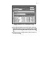
Fig. 10. The preferences set before the start of the observations.
moving it to the center of this big aperture, the aperture wheel must be
changed to the same size working aperture, as it was set for the Ch1-3, to
1.6mm in our case. To have this aperture in Ch2 too, on the handpaddle
must be: Motor "4", Position "5" (Table 2a in the Appendix 1). Do the
nal centering of the star in this aperture too. Withdraw the prism from
the Ch2 light path with M2P
After this action photometer is ready for the time-series photometry
of the selected stars.
3.5. Continuing "Auriga" program settings and data recording
Program "AURIGA" preparation for the observations:
Step 1 - The next step in preparations is setting the preferences for the data record-
ing. Click "Photometer" { "Preferences". The panel of preferences pops
down and one must ll-in the data in it according the plans of observations
(Fig.10).
Step 2 - Here must be set sizes of the work-apertures for every channel, and marked
the holes of the 10-hole-disk of the photometer, where the lters for this
observation were placed. Even if observations were planned in the integral
light, through one hole, this hole box must be marked and some name
(letter) must be there. Then system will know that the lter disk must
stay still at this hole and data in the data le will be marked with this
fake lter letter too.
Step 3 - Computer data and time should be checked to be the recent one. If there
are problems with the GPS system, then it is possible to make photometry counting on computers initial clock. Actually, the system accepted
computer time after the linking and initialization procedure already. And,
if computer time will be used, it should have been set to the correct time
as exactly as possible before the initialization.
16
Fig. 11. Auriga's panel for the system linking to the GPS unit and the panel
of the GPS preferences.
Step 4 - Much better timing may be reached if computer clock is synchronized
with the GPS time signals. This may be done from the AURIGA main
window: menu "Tools" { submenu "GPS Link". The "GPS Link" window
shows Port number, IRQ number and communication speed. They are set
according the system requirements and are accepted as they are, usually.
Clicking "Link" button starts the process of computer linking to the GPS
unit. When everything went smoothly message "Port ready" appears,
and after "OK" the panel of GPS preferences pops down. In this panel
observer can see the GPS data. If data is acceptable, and receiver "sees"
enough (not less than three) satellites, then button "Interface" nishes the
linking process - after 10s system gives the sound signal, and the blue
clock icon in the right upper corner of the main Auriga's panel changes
into the "happy" one with the GPS letters in it. After this procedure, it
is possible to adjust computers initial clock with the GPS system too {
click the "PC" button in the same panel for that. All this process may be
repeated if for some reasons the linkage failed, but before that: "Tools" {
"GPS Link" { "Unlink" must be performed.
Step 5 - In the AURIGA's "Notes" le must be written all necessary information
related to the recent observations. It must contain the information about:
the site (observatory), the telescope, the photometer, observers, weather
conditions, as well as the main technical information { instrumentation
operating modes (values of high voltage, cooling mode, ), photomultipliers,
software used etc.
4. AT THE OBSERVATIONS
If the above mentioned procedures are performed, then it is time to check if
the Ch1 and Ch2 stars are still in their apertures and centered (use handpaddle
again { as it was explained above, in actions 5 and 7).
If High Voltage is not "ON" yet, it is time to start it { the switch HV on
the Power Box PB in the Fig.4.
17
Fig. 12. Auriga's window as it is at the data oats in.
To start data counting and recording click button "GO in the main Auriga's
panel under the menu bar. Lines of data numbers starts to show up in the upper
left main panel window and the data points { in the lower window of it. If the
Ch1-3 and Ch2 shutters are still closed, these numbers and point positions must
be quite low - the dark counts. To start recording data of stars { open them
(SH1 and SH2 in Fig.7).
4.1. Continuous time series observations of the variable star
should be executed in the following order:
Darks-1 Recording of the dark counts in all three channels (at the closed shutters
of both channel units (SH1, Sh2 in Fig.7). Must be recorded about 10
points.
Sky-1 First recording of the sky background in all three channels. Shutters open, but stars moved 5 aperture sizes away. The best is to control
this oset in the autoguiders monitor, where the size of the aperture is
marked. Must be recorded about 10 points too. It is good idea to check
if there were no changes in the background (Ch3 data), when images of
stars were moving { it gives some understanding if there is good place for
the background selected.
18
Stars Observations: return stars to the centers of their apertures and do record-
ing of the data of the target star in Ch1, comparison star { in Ch2 and sky
background in Ch3. Every problem with the sky or the instrumentation
must be written in the log le.
Sky-2 Final recording of the sky background in all three channels. Star images
must be moved approximately to the same place where they were at the
rst sky recording, and about 10 data points must be recorded again.
Darks-2 Final recording of the dark counts in all three channels. Close both shutters (SH1 and SH2) and record the nal 10 points.
Stop Stop data recording by clicking the same "GO" button at the top of
the Auriga's main panel. Actually this button has three functions - the
mentioned start and stop of the data recording. But if after recording
is stopped, and "GO" would be 'clicked' again, observations would be
continued with the recording of the data into the same binary le which
was used before. So, "GO" button can perform the PAUSE function too,
making some gap in the recorded data.
The system records data into automatically made in-le continuously, after
each integration and data does not disappear even at power failure. It is
even possible to continue data writing - appending to the same le after
new load and initialization of the system with menu commands: "File" {
"Restore" and "GO"
5. AT THE END OF OBSERVATIONS
The binary data le, which was used for the data recording, was named by
the Auriga automatically - with some letters and numbers. It is good idea to rename it at the nal saving to something more informative, e.g. PG1336A.RAW.
Do that with "File" { "Save As" in the Auriga's main panel, and make "File"
{ "Exit" to stop the Auriga.
The last action - the power switches. If it is the nal observation of the
campaign, or to leave power "ON" is not safe for some reason, then must be
switched o the HV power and 24V power, as the last step of the observations
(switches HV, 24V in the Fig.4).
6. RECOMMENDATIONS
1. Sky maps with the useful eld circles drawn on them should be prepared
| e.g. the eld for nding of the accessible comparison star, all eld of
the viewnder eyepiece.
2. The photometer should be switched on (high voltage and cooling selected
for the season) two or three hours before the observations. It is necessary
for stabilizing of the sensitivity of all detection channels. The best case is
if high voltage and cooling are not switched o for all run of observation
{ all nights and days.
19
Fig. 13. Auriga's window with the nal savings of the data.
3. Dark counts without cooling and with cooling should be checked every
evening after switching the photometer "ON", before the start of observations and after the observations. Comparing these values with the ones
received in the previous days, makes possible to control the system stability.
4. It is good idea to check the signal counts from standard sources (SS) in
all channels periodically.
20
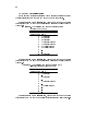
APPENDIX 1: Position values
In the next few tables it is explained what means the position number in
the right indicator above the word "POSITION" on the handpaddle.
When the "MOTOR" value is "1", then "POSITION" number means
that in front of the Ch1 and Ch3 are placed such a lters of the lter wheel "A"
(Table 1a.):
Table 1a. The positions and names of lters in lter
wheel "A" of Ch1/Ch3
Position Filter
in the wheel name
1 U (Johnson)
2 B (Johnson)
3 B (Johnson)
4 V (Johnson) for S20
5 V (Johnson) for S20
6 R (Cosins) for S20
7 R (Cosins) for S20
8 {
9 {
10 U (Johnson)
When the "MOTOR" value is "2", then "POSITION" number means
that in front of the Ch1 and Ch3 are placed such a lters of the lter wheel "B"
(Table 1b.):
Table 1b. The positions and names of lters (UBVR
lter set) in lter wheel "B" of Ch2
Position Filter
in the wheel name
1 U (Johnson)
2 {
3 B (Johnson)
4 {
5 V (Johnson) for S20
6 {
7 R (Cosins) for S20
8 {
9 {
10 {
When the "MOTOR" value is "3", then "POSITION" number means
that in front of the Ch1 and Ch3 are placed apertures of such a size (Table 2a.):
21
Table 2a. Positions and diameters of apertures in aperture wheel "A" of Ch1/Ch3
Position Diameter Diameter in arcunits
in the wheel (mm)
1.65 m Mol_etai tel.
1
8.0
1'.4
2
1.6
16".8
3
1.6
16".8
4
1.1
11".5
5
1.1
11".5
6
0.8
8".4
7
0.8
8".4
8
0.6
6".3
9
0.6
6".3
10
Standard Light Source
When the "MOTOR" value is "4", then "POSITION" number means
that in front of the Ch2 are placed apertures of such a size (Table 2b.):
Table 2b. Positions and diameters of apertures in aperture wheel "B" of Ch2
Position Diameter Diameter in arcunits
in the wheel in mm
1.65 m Mol_etai tel.
1
8.00
1'.4
2
6.50
1'.1
3
3.25
34".1
4
2.25
23".6
5
1.60
16".8
6
1.10
11".5
7
0.80
8".4
8
0.60
6".3
9
0.40
4".2
10
Standard Light Source
When the "MOTOR" value is "5", then:
"POSITION" number "1" means that the prism in the Ch1-3 microscope
(M1-3 in Fig.6) is positioned so, that in its ocular may be observed the Ch1
aperture picture (the target star);
"POSITION" number "2" means that the prism in the same Ch1-3 microscope (M1-3 in Fig.6) is positioned so, that in its ocular may be observed the
Ch3 aperture picture (the sky background);
22
APPENDIX 2: Abbreviations and markings in the pictures
Ch1
Ch2
Ch3
RF
RL
RH
FL
FLP
FLF
R1
RP
L1
LP
L1F
L1H
M1-3
M2
SH1
SH2
HV1, HV2, HV3
A1, A2, A3
S1, S2, S3
CL
FM
D
CL1-3
CL2
M2P
HSTCP
HV
PMT
SS
UBVR
First Channel
Second channel
Third channel
Rotator xator
Rotator limb
Rotator ne movement handle
Field lens - the main viewnder
Field lens raw positioning
Field lens ne positioning
Field lens position ruler
Field lens position pointer
Ch2 angular position limb
Ch2 limb pointer
Ch2 limb rotation stopper
Ch2 angular positioning handle
Aperture microscope for Ch1 and Ch3
Aperture microscope for Ch2
Ch1 and Ch3 shutter
Ch2 shutter
Ch1, Ch2, Ch3 High voltage inputs
Ch1, Ch2, Ch3 ampliers
Ch1, Ch2, Ch3 signal outputs-inputs
Field lens croshair illumination regulator
Field mirror IN-OUT handle
Ch3 slight deviation knob
Ch1, Ch3 aperture illumination regulator
Ch2 aperture illumination regulator
Ch2 microscope prism IN-OUT handle
High-Speed Three-Channel Photometer
High Voltage output
photomultiplier Tube
Standard Source
names of passbands of Johnson's
photometric system
23
APPENDIX 3: Technical specications of the HSTCP
Number of channels
3 (Ch1 { target star. Ch2 {
comparison star. Ch3 { sky
background
Distance between Ch1 and Ch2
25.3 mm to 51.4 mm
Distance between Ch1 and Ch3
20 mm
Possible deviation of the Ch3
2 mm
Number of lter wheels
2 (one for Ch1+Ch3 and other for Ch2)
Number of lters in each lter wheel 10 in Ch2 and 5 pairs in Ch1+Ch3
Diameter of lters
13 mm
Number of aperture wheels
2 (one for Ch1+Ch3 and other for Ch2)
Number of apertures in each wheel 10 in Ch2 and 5 pairs in Ch1+Ch3
Diameters of apertures
0.4 to 8.0 mm (see Tables 1a and 1b)
Diameter of eld eyepiece
40 mm
Number of aperture microscopes
2 (one for Ch1+Ch3 and other for Ch2)
Magnication of microscopes
25
Diameter of the eld of microscopes 8 mm
Number of Fabry lenses
3
Diameter of Fabry lenses
14 mm
Focal length of Fabry lenses
34 mm
Time of the lter wheel turn:
to the neighboring position
0.08 s
over 5 positions
0.20 s
Photomultiplier type
Hamamatsu R470P (S20)
spectral range
185 to 850nm
Photometric systems
UBVR and Vilnius
Detection mode
photon counting
Dead time of photon counters
222 ns
PMTs cooling system
two one-stage thermoelectric coolers (one for Ch1+Ch3 and other
for Ch2) with actively ventilated
air heat absorber
Temperature of the PMTs
two stabilized
temperatures: ;5 C
and ;15 C which can be set
according to the environmental
temperature
Time synchronization system
using GPS receiver
accuracy of absolute timing
2s
Maintenance of accuracy using
5 ms per 12 hours
only inner oscillator
24
Technical specications (cont.)
Communication between PC and
interface
Data transfer rate
Minimal integration time
Power supply requirements
Dimensions of the photometer:
height
max. diameter (including microscope)
max. diameter of the main frame
Distance from the mounting plane
of the rotational bearing to the
focal plane of the photometer
Weight
via RS232 port
19.2 kbd
20 ms
220 V
4105 mm
2105 mm
1405 mm
200 mm
31 kg