1
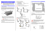
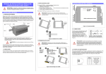
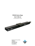
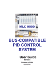
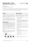
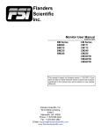
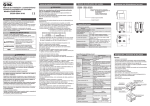
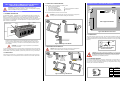
To install the Bus Module follow the instructions below:
1.1 GENERAL DESCRIPTION
The MLC 9000+ System - comprising one or more Bus Module each with up to eight Loop
Modules - is designed for installation in an enclosure which is sealed against the ingress of
dust and moisture. The enclosure must contain sufficient length of 35mm Top-Hat DIN
mounting rail to accommodate the system modules (see below) plus an extra 50mm of rail to
permit modules to be separated for removal/replacement. The space required by the MLC
9000+ modules is shown below.
22mm
30mm
DIN Rail Clamp
Power Input
18 – 30V dc
30W Max
0V 2
+24V 1
1. INSTALLATION - MECHNICAL
2. INSTALLATION – ELECTRICAL (GENERAL)
The MLC 9000+ system is installed in the following order:
1.
Bus Communications Module
2.
Interconnect Module(s)
Refer to Loop Module installation
3.
First Loop Controller Module
instructions
4.
Second Loop Controller Module
5.
Third Loop Controller Module etc…..
Configuration
Port
CAUTION: Installation and configuration should be performed only by
personnel who are technically competent to do so. Local Regulations regarding
electrical installation & safety must be observed.
1.3 INSTALLING THE BUS MODULE
CAUTION: Ensure that the power has been removed from all equipment
currently in the enclosure before installing the Bus Module
120mm
Click!
Field Bus Port
MLC 9000+ BUS COMMUNICATIONS MODULE
INSTALLATION MANUAL 59325-1
Use Copper Conductors
100mm
Figure 4 Bus Module Connections
2.1 POWER INPUT
The system requires a power input of 18 - 30V DC and has a maximum power consumption
of 30W. It is recommended that the power supply is connected via a two-pole isolating switch
(preferably situated near the System) and a 2A slow-blow fuse or a 2A Type C MCB (see
Figure 5).
NOTE: An additional 60mm of space is required above and below the system
modules to permit ventilation and to accommodate wiring bend radii to enclosure
trunking or conduits. Allow sufficient slack in all cables inside the trunking to permit
“hot” swapping of modules (i.e. modules to be removed/replaced whilst the system
is under power).
WARNING: The maximum of eight Loop Module’s per Bus Module
must not be exceeded.
It is recommended that (a) some means of preventing unauthorised access to the enclosure
interior (e.g. lockable doors) is provided, and (b) that a suitable DIN rail clamp be used, once
the MLC 9000+ system is fully installed, to prevent the system from moving on the DIN rail.
1
1.4 REMOVING THE BUS MODULE
Unplug all
connectors
from the Bus
Module
DIN Rail
Bus
Module
Slide Loop
Modules/
Interconnect
Modules clear
2A
+24V
Figure 5 Recommended Mode
of Power Connection
CAUTION: Ensure that the power has been removed from all equipment
currently in the enclosure before uninstalling the Bus Module
1.2 VENTILATION
Under normal circumstances, no forced ventilation is required and the enclosure need not
contain ventilation slots, but temperatures within the enclosure must be within specification.
0V
2
Figure 2 Installing a Bus Module
CAUTION: The system is designed for installation in an enclosure, which
provides adequate protection against electric shock. Local regulations
regarding electrical installation and safety should be rigidly observed.
Consideration should be given to prevention of access to the power
terminations by unauthorised personnel.
2.2 CONFIGURATION PORT
This connects the Bus Module to a local PC for configuration. The configuration port uses the
point to point connection specification RS232. Pin connections are shown on the right. This
port can only be used for configuration purposes only using the MLC 9000+ configuration
software. (Part number MLC 9000-AN111)
Pin
No.
Figure 3 Removing a Bus Module
1
2
3
4
RJ11 Connector
Signal /
Function
1
Receive Data
2
Transmit Data
3
No connection
4
Signal Ground
3. INSTALLATION – ELECTRICAL (FIELDBUS PORT)
4. BUS MODULE SPECIFICATION
3.1 MODBUS – BM220-MB Bus Module only
This connects the Bus Module to a MODBUS master device (local operator interface/display
or multi-drop PC operator and configuration
network). The Modbus Fieldbus port uses the multi(Red) Tx/Rx+ (A)
drop connection standard RS485. Pin connections
are shown on the right. The Common connection is
(White) Tx/Rx– (B)
provided for termination of screened (shielded)
(Green) Common
cable.
Configuration
Port:
(All Bus Modules)
MODBUS Port:
(BM220-MB only)
3.2 CANopen/DEVICENET – BM230-CO or DN Bus Modules only
Both the CANopen and DeviceNet fieldbus protocols use the same CAN hardware standard.
When installed with the CANopen firmware (BM230-CO) the Bus Module can be connected
to a CANopen enabled master device. CANopen compliant cables and connectors must be
used when connecting to the network. When installed with the DeviceNet firmware (BM230DN) the Bus Module can be connected to a DeviceNet enabled master device. DeviceNet
compliant cables and connectors must be used when connecting to the network. Both
CANopen and DeviceNet networks must
be terminated with 121ohm resistors
V+ (Red)
between CAN_L and CAN_H at each
physical end of the CAN network. A
CAN_H (White)
separate 24V power supply should be
SHIELD
used to power the network between V+
CAN_L (Blue)
and V-. Terminal connections are shown
V- (Black)
on the right.
The SHIELD connection is provided for
termination of screened (shielded) cable.
DeviceNet Port:
(BM230-DN only)
PROFIBUS Port:
(BM240-PB only)
Note: Most DeviceNet communication problems are caused by incorrect
wiring and power supply selection if any problems are encountered the
DeviceNet website has guidelines on wiring a DeviceNet system.
(www.odva.org)
3.3 PROFIBUS – BM240-PB Bus Module only
This enables the Bus Module to be
connected to a PROFIBUS-DP master
device (local operator interface/display,
PLC or multi-drop PC operator and
configuration network). PROFIBUS
compliant cables and connectors must be
used when connecting to a network. Pin
connections are shown on the right. For
more information on PROFIBUS consult
the PROFIBUS website
(www.profibus.com)
9
6
Ethernet/IP Port:
(BM250-EI only)
5
3
4
5
6
7
RxD/TxD+
CNTR-P
DGND
VP
RxD/TxD-
MODBUS/TCP
Port: (BM250-MT)
CANopen Port:
(BM230-CO)
1
Supply Voltage
3.4 ETHERNET/IP & MODBUS TCP/IP – BM250-MT or EI Bus Modules only
This connects the Bus Module to an Ethernet/IP or MODBUS TCP/IP enabled master device
(local operator interface/display, PLC or multi-drop PC operator and configuration network).
The connection is via RJ45 connector that conforms to CAT 5 cabling and 568A, 568B wiring
sequences. The BM250 supports 10BaseT and 100BaseT.
Pin No.
568A
568B
GENERAL
This is a local port for connection to an RS232 port on a PC for
local operator configuration. It has EIA-232-E (RS232) compatible
inputs and outputs for TxD and RxD and provides facilities via the
MLC 9000+ Workshop Software to configure the MLC 9000+
system.
This is an optional RS485 port for connection to a MODBUS
master device. Data rate and format are configurable via the
RS232 port.
MODBUS RTU protocol is supported, using an RS485 physical
layer. The load is no greater than one-quarter unit load. The data
rate is selectable from 4800, 9600 or 19200 Baud. It is factory-set
to 9600 Baud. Parity is selectable from none, even or odd.
The base address can be set in the range 1 - 247 (default = 96)
Node addressing, data rate and character format are selectable
via the MLC 9000+ Workshop Software running on the PC
connected to the RS232 Port.
This is a port for connection to a DeviceNet master device. Data
rate and MAC ID are configurable via the configuration port.
The data rate is selectable from (in kbps) 125, 250 or 500. It is
factory-set to 125kbps.
The MAC ID can be set in the range 0 - 63 (default = 63).
This port is for connection to a PROFIBUS DP network.
The PROFIBUS data rate is automatically detected and set by the
Bus Module.
The PROFIBUS interface can communicate at the following data
rates; 9.6kbps, 19.2kbps, 45.45kbps, 93.75kbps, 187.5kbps,
500kbps, 1.5Mbps, 3Mbps, 6Mbps, 12Mbps.
PROFIBUS address and byte order are configurable via the
RS232 port.
The PROFIBUS address can be set in the range 0 to 126
(126=default).
This port is for connection to an Ethernet/IP network.
10/100BaseT, user definable IP address, MAC ID 0 – 63 (Default
ID 63) Configured using the MLC9000+ Workshop software, via
the configuration port
This port is for connection to an MODBUS/TCP network
10/100BaseT, user definable IP address Configured using the
MLC9000+ Workshop software, via the configuration port
This port is for connection to an CANopen network
Data Rate 125kbps, 250kbps, 500kbps or 1024kbps. MAC ID 1 –
127 (Defaults 125kbps, ID 1). Configured using the MLC 9000+
Workshop software, via the configuration port
18 to 30V DC (including ripple) 30W maximum
ENVIRONMENTAL
Operating
Conditions
Storage
Conditions
Ambient Temperature: 0°C to 55°C
Relative Humidity: 30% to 90% non-condensing
Ambient Temperature: -20°C to 80°C
Relative Humidity: 30% to 90% non-condensing
EMC standard
EN61326-1.
APPROVALS MODBUS
1
WHITE/green
WHITE/orange
Safety
Complies with EN61010-1 and UL 3121-1.
2
GREEN/white
ORANGE/white
Certification
Awaiting Certification from the MODBUS organization
3
WHITE/orange
WHITE/green
4
BLUE/white
BLUE/white
EMC standard
EN61326-1.
5
WHITE/blue
WHITE/blue
Safety
Complies with EN61010-1 and UL 3121-1.
Certification
Awaiting Certification from the ODVA
EMC standard
EMC EN61326:1998.
Safety
Complies with EN61010-1:1995 and UL 3121-1:1998.
Certification
Awaiting Certification from PROFIBUS Organisation
6
ORANGE/white
GREEN/white
7
WHITE/brown
WHITE/brown
8
BROWN/white
BROWN/white
For full information on configuration of the communication interface consult the MLC 9000+
User Manual (part number 59327).
APPROVALS DeviceNet
APPROVALS PROFIBUS
APPROVALS Ethernet/IP
EMC standard
EMC EN61326:1998.
Safety
Complies with EN61010-1:1995 and UL 3121-1:1998.
Certification
Awaiting Certification from ODVA
EMC standard
EMC EN61326:1998.
Safety
Complies with EN61010-1:1995 and UL 3121-1:1998.
Certification
Awaiting Certification from the MODBUS organisation
EMC standard
EMC EN61326:1998.
Safety
Complies with EN61010-1:1995 and UL 3121-1:1998.
Certification
Awaiting Certification from CiA
APPROVALS MODBUS TCP/IP
APPROVALS CANopen
Dimensions
Mounting
Connectors
Weight
PHYSICAL
Height - 100mm; Width - 30mm; Depth - 120mm
Directly mounted on 35mm x 7.5mm Top Hat DIN rail (EN50022,
DIN46277-3)
Power input:
2-way 5.08mm Combicon type
RS232 port:
6-way RJII Type
BM220 port:
3-way 5.08mm Combicon type
BM230 port:
5-way 5.08mm Combicon type
BM240 port:
9-way D-type
BM250 port:
RJ45 Type
0.21kg