1
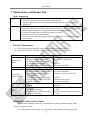
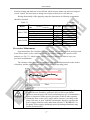
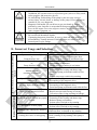
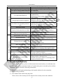
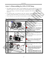
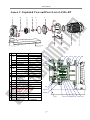
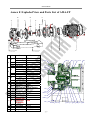
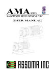
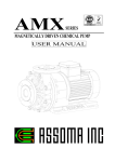
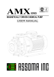
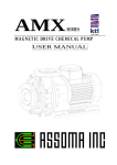
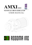
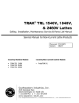
AMA SERIES MAGNETICALLY DRIVEN CHEMICAL PUMP USER MANUAL Symbols used Situation where improper handling or operation failure to follow this manual would almost certainly result in death or serious bodily injury. Situation where improper handling or operation failure to follow this manual could result in death or serious bodily injury. Situation where improper handling or operation failure to follow this manual could result in bodily injury or equipment damage. AMA SERIES Table of Contents 1. Foreword.......................................................................................... 2 2. Safety Requirements........................................................................ 2 3. Inspecting the Pump Prior to Unpack the Carton/ Install the Pump 3 4. Installation, Piping and Wiring ........................................................ 4 5. Notes for Operation ......................................................................... 8 6. Operating Procedure and Notes ................................................... 10 7. Maintenance and Inspection ........................................................ 12 8. Incorrect Usage and Selection ..................................................... 14 9. Repair and Warranty .................................................................... 15 Annex A. Disassembling the AMA-CT/EP Pump............................ 16 Annex B. Exploded View and Parts List of AMA-CT ..................... 18 Annex C. Exploded View and Parts List of AMA-EP ..................... 19 Annex D. Disassembling the AMA-DT/FP Pump ........................... 20 Annex E. Exploded View and Parts List of AMA-DT ..................... 22 Annex F. Exploded View and Parts List of AMA-FP ...................... 23 Annex G. Description of ATEX-specific marking............................ 24 1 AMA SERIES 1. Foreword Thank you for purchasing an ASSOMA pump. To ensure proper operation and maximum efficiency, please read this instruction manual carefully. Failure to follow the recommended operating conditions outlined in this manual may result in serious personal injuries and/or equipment damage. 2. Safety Requirements This section lists general information about the safety. The relevant safety requirements of installation, wiring, operation and maintenance will set out in the relevant sections. ASSOMA INC. does not assume responsibility for personal danger or property damage resulting from failure to follow the safety instructions contained herein. 1. The explosion-proof grade of AMA series is varied according to materials used together with type of motor matched. Please follow the order specification sheet or contact ASSOMA’s local agent. 2. Be sure to turn the power off before any wiring or disconnection operations. 3. The customer should not modify the pump under any circumstances. Doing so could result in an unexpected accident. ASSOMA INC. shall not be responsible for accidents or damage resulting from equipment modified by the customer. 4. Be sure to take special precautions when performing operations if using hazardous, explosive or inflammable liquids. 5. Magnetic field hazard: AMA rotor (including the drive magnet and driven magnet) uses strong permanent magnet. Pay attention to potential hazards from powerful magnetic fields to persons, such as, who are assisted by electronic devices. 1. The pump operator and pump operation supervisor must not allow any operator who has little or no knowledge of the pump to run the pump. Pump operators must have a sound knowledge of the pump and its operation. 2. Do not use a damaged pump. Doing so could result in injury or fire. 3. Keep away from heat or flame: Do not place any open flame or flammable object near the pump. 1. Transport, installation, piping and wiring connections, operation, adjustment, maintenance and inspection should be carried out by qualified personnel. Having unqualified personnel perform these tasks could result in electrical shock, injury or fire. 2. Do not block name plate or warning labels for view. 3. Do not stand on the pump or use the pump as s step under any circumstances. Otherwise, you may experience a serious injury. 4. Disposal of used or damaged pump must be done in accordance with local laws and regulations. 2 AMA SERIES 3. Inspecting the Pump Prior to Unpack the Carton/ Install the Pump (1) Check the pump exterior for any physical damage that may have been incurred during shipping. (2) Use a small screwdriver to rotate the impeller of the motor’s cooling fan. The fan should turn easily. If the fan feels tight or if there are unusual sounds, the interior of the pump may have been damaged during shipping. (3) If there is any damage to the pump, contact the shipping company and the distributor immediately to determine who should pay for the damage, and to arrange for replacement parts. (4) Each pump has a nameplate, indicating the pump model, MFG number, rated head, flow rate, and motor power, voltage and frequency. Check these data to ensure they comply with your order and application. (5) When using versatile motor with 50Hz and 60Hz compliance, be sure to use suitable diameter of impeller according to the frequency of power. A wrong diameter can cause the motor overload (frequency is too high) or insufficient pump performance (frequency is too low). (6) The information of nameplates on motor and pump is key for operation setup and pump maintenance. Please keep the nameplate intact for reference. (7) The nameplate of a pump indicates the optimum point of its operation. Therein, Total Head= Static Head + Dynamic Head. 2 V - V1 Total Head H S 2 2g 2 The pump is designed and manufactured to the specifications agreed upon by the user and ASSOMA INC. such as fluid composition, fluid temperature, working pressure, environmental conditions and necessary operational information. Use the pump strictly in accordance with the pump specifications and application range. If the user intends to change any specification, contacts ASSOMA INC. or the authorized dealer in the near region to obtain the permission in writing before operation. Unpack a pump for inspection without proper hoisting or support of lifting equipment may cause serious personal injury or damage to the pump. 3 AMA SERIES 4. Installation, Piping and Wiring 4.1 Installation Location (1) The pump should be close to the ground and located near the inlet tank. (2) There should be sufficient space reserved around the pump to facilitate future maintenance and repairs. (3) The pump and its wiring should be placed in a relatively dry environment, protected from possible flooding. (4) Install in the place where the ambient temperature is not above 40°C. (5) Fastening the pump to base plate or machine with anchor bolt. 1. Be sure to use the hanger bolt to lift the pump. Do not hang with the other position of the pump. When hoisting, do not pass under a raised pump. A serious injury could occur if the pump is accidentally dropped. 2. Before lifting, check the weight of the pump. Do not lift a pump which exceeds the rated weight of the hoist. And, be sure no one standing below the pump while lifting or transporting. Install or store the pump in the following places with special care and consult with ASSOMA INC. or authorized dealer in the near region: a. Places where flammable gas, dust or material is used or placed. b. Places where corrosive gas is generated. Places where the ambient temperature is extremely higher than 40°C or extremely lower than 0°C. 4.2 Piping (1) AMA flange screw is either M16 or 5/8”. (2) The allowable load of pipe on the pump. Z X Y Z X Y SUCTION Model AMA-EP AMA-CT AMA-DT AMA-FP Fx 1600 1200 1600 1300 Force (N-m) Fy Fz 1200 1000 1100 900 1200 1000 1200 1000 ΣF 1800 1500 1800 2000 4 Mx 600 600 600 700 Moment(N-m) My Mz 500 500 500 500 500 500 700 700 ΣM 900 900 900 1000 AMA SERIES DISCHARGE Model AMA-EP AMA-CT AMA-DT AMA-FP Fx 800 800 900 900 Force (N) Fy Fz 900 1000 900 1000 1000 1000 1200 1000 ΣF 1500 1500 1500 1600 Mx 600 600 700 700 Moment(N-m) My Mz 500 600 500 600 600 700 600 700 ΣM 800 800 1000 1000 Notes for Installing the Piping System 1.Outlet Piping 2.Throttle Valve 3.Priming Piping 4.Priming Valve 5.Check Valve 3 6.Outlet Pressure Gauge 4 7.Motor 8.Pump 9.Inlet Pressure Gauge 10.Inlet Piping 9 11.Inlet Piping Support 11 12.Vibration Damper 10 13.Filter 14.Inlet Tank 13 12 15.Foot Valve 14 1 Bad 2 5 8 6 7 Good 0.01~0.02 slope 15 Fig. 4.1 Fig. 4.2 Bad Piping Designs >0.5m or >2D >1.5D D=Diameter Fig. 4.4 Fig. 4.3 5 >1.5D AMA SERIES Procedure Inlet Piping General Requirements Inlet Piping Foot Valve Self-Priming Cylinder Control Valve Filter Outlet Piping Vacuum Gauge General Requirements Priming Piping Items to Note 1. Suction condition must satisfy NPSHa>NPSHr+0.5m 2. Reduce inlet Head as much as possible. Use straight and short piping. 3. The pipes should have adequate structural support and shouldn’t use the pump as its primary support. (see Fig. 4.1) 4. When designing supports, consider the effects of temperature changes on the supports to avoid thermal stress. 5. Inlet piping and connectors should be installed properly to prevent sucking in air. 6. The piping system should not have upward bumps that may collect air. The inlet piping should also have a 0.01~0.02 slope increase towards the pump. (see Fig. 4.2) 7. There should not be any elbows for at least 5 times the pipe diameter from the opening of the pump. The elbow closest to the pump opening should be a long radial elbow. 1. There should be at least a 1.5 diameter distance between the pipe inlet and the closest tank wall to prevent circulation. (see Fig. 4.4) 2. The submerge depth of the inlet should be at least 0.5m or at least twice the pipe diameter below the liquid surface. (see Fig. 4.4) 3. There should be a distance of at least 1.5D between the bottom of the tank and the beginning of the inlet pipe opening. (see Fig. 4.4) 4. If there are two or more inlet piping in the same tank, they should be placed at least 3D apart to prevent mutually disrupting each other’s flow. Please install a foot valve if upward suction is used. (see Fig. 4.1) 1. If suction method is upward suction, please install a self-priming cylinder to prevent dry-running due to a leaking foot-valve. 2. The size of the self-priming cylinder should have a minimum liquid level of at least 0.5m above the opening of the pump. 1. A control valve should be installed to make disassembling of the pump easier. The valve should only be shut off when the pump is to be detached for maintenance or repairs. 2. We recommend the use of valves that have the least loss when fully opened, like a gate valve. 1. It is generally not recommended to install a filter in front of a pump, which can unpredictably increase suction system resistance. 2. If a filter has to be used, it should be cleaned regularly to ensure a smooth flow. 1. The material used should be corrosion resistant; otherwise, a pressure gauge diaphragm should be used. 2. During operation, if the vacuum gauge reading fluctuates, either there are air bubbles in the system or cavitation has occurred. 1. The weight of the outlet piping should be properly supported to prevent putting excessive stress on the pump. (see Fig. 4.1) 2. A priming piping must be installed if the suction system does not employ positive pressure, i.e. upward suction. (see Fig. 4.1) 3. The flow rate in the outlet piping should not exceed 3m/sec. 4. The ability for each component in the piping system to withstand pressure should be calculated, to determine the maximum allowable operating pressure. Upward suction pumps that do not have a self-priming cylinder should have a priming piping system. 6 AMA SERIES Procedure Items to Note 1. Pressure gauge used should be able to read beyond the maximum operating pressure. 2. Pressure gauge should be made of material that is corrosive resistant; Pressure otherwise a diaphragm should be used. Gauge 3. A valve can be installed on the piping that leads to the pressure gauge, to facilitate maintenance and to lengthen the gauge’s service life. 4. During operation, if the pressure gauge reading fluctuates, either there are air bubbles in the system or cavitation has occurred. A check valve should be installed in the following situations: 1. Outlet piping is long. 2. Head of outlet is more than 15m. Check Valve 3. Discharge pressure exceeds 2kg/cm2 and flow rate exceeds 3m/sec. 4. Two or more pumps share the same outlet piping system. 5. To prevent back flow (water hammer) from damaging the pump during unexpected power outages. 1. A control valve can be used for controlling the flow of fluids. Do not run the pump with the control valve closed for an extended period of time. 2. When starting the pump, always start with a closed valve, and then slowly open the valve to obtain the desired operating pressure and flow. Always open Control Valve or close the valve gradually. 3. To facilitate the adjustment of discharge flow and the adjustment of motor overload, it is recommended to install valves on outlet piping. And if both a check valve and a control valve are to be installed, the order of allocation is pump => Check Valve => Control Valve. Exhaust A vent should be installed if the horizontal section of the outlet piping is very Valve long. Cautions when dangerous liquids are transferred: When the pumps are used to transfer the dangerous liquids mentioned as below, the pumps, piping and fittings must be checked and watched so that the liquids can not be leaked. Leaking the liquids may result in personal injury and/or explosion, fire accidents. a. Explosive and inflammable liquids. b. Corrosive and stimulus toxic liquids. c. Liquids could directly harm the human body or detrimental to health. d. Liquids could produce a chemical reaction. Wiring The wiring system should be done properly, using premium equipment and complying with rules and standards set by the electrical company. The following recommendations should also be implemented: (1) (2) (3) Power frequency, voltage and capacity should strictly follow according to motor specification sheet and name plates Please select the proper non-fuse switch (NFB) according to the rated current of the motor. When using the pump for outdoor applications, please make sure the switch is protected from rain. 7 AMA SERIES (4) (5) (6) Keep the electromagnetic contactor (MC) from a pump with suitable distance, and clearly mark warning sign to avoid false start. Tags at the end of wires (or Diagram shown in the terminal box) and method of connection are based on the number wires (phases), power voltage and mode of start for the motor. Be sure to connect the power cable in accordance with name plate for the motor and the connection diagram in the terminal box Select the proper size of wire for power wiring, and tighten screws to prevent loosening. Table 4.1 lists the reference value, and make sure to follow local electrical regulations. Table 4.1 Wire diameter and terminal locking torque Minimum diameter Locking torque 7.5Hp 200~230V 5.5 mm 30 kgf-cm 380~480V 2.0 mm 30 kgf-cm 10Hp 200~230V 8.0 mm 30 kgf-cm 380~480V 2.0 mm 30 kgf-cm 200~230V 14.0 mm 30 kgf-cm 15Hp 380~480V 5.5 mm 30 kgf-cm 200~230V 22.0 mm 30 kgf-cm 20Hp 380~480V 8.0 mm 30 kgf-cm 200~230V 30.0 mm 30 kgf-cm 25Hp 380~480V 14.0 mm 30 kgf-cm 1. Be sure not to performing any type of maintenance while the power turns on. It may lead to electric shock. 2. Power supply and wire connecting work should be performed by qualified personnel only. 3. After wiring, be sure to replace the terminal box cover in its original position. Failure to do so could result in electrical shock. 1. Install an earth leakage breaker: The operation of a pump without using an earth leakage breaker may cause an electrical shock. Install an optional leakage breaker in the system before running operation. 2. Grounding wire should be consistent with the third type of grounding (grounding resistance is 10Ω or less). 3. Each pump must have a separate grounding wire directly connected to the common ground terminal, and must not form a loop between wires. 4. If the long wiring results more than 3% voltage drop in the line, replaces with bigger size of wires. 5. Notes for Operation 5.1 Dry-Running (1) Our pump use the transfer fluid as its internal cooling system, therefore, dry-running the pump can cause the temperature to rise to a dangerous level that may seriously damage the pump. (2) If dry-running occurs, switch off the pump immediately; let it cool for at least an hour 8 AMA SERIES before priming the pump to prepare it for normal operation. NOTE: Do not subject the pump to rapid cooling, which may damage the internal parts. (3) We recommend using a dry-run protector to detect dry-run occurrences to avoid causing unnecessary damage to the pump. 5.2 Operating Temperature (1) Operating temperature may change the fluid’s viscosity, vapor pressure, and corrosiveness. Please ensure that your pump is operating within the proper temperature range. (2) The optimal temperature range for pumping pure water: o Body material ETFE+CF:0~95 C (3) Please consult the distributor for the temperature range suitable for your chemicals. o o (4) We recommend the operating environmental temperature to be between 0 C ~ 40 C. When the pump is used to feed a hot liquid, do not touch the front cover or the piping with your bare hands. It may cause burns. Any reachable hot surfaces, including pumps, motors and piping, must provide isolate device and display obvious warning signs for high temperature. 5.3 Concentrations, Viscosity and Specific Gravity (1) A change in a fluid’s concentration will usually affect its viscosity and specific gravity. Other physical properties like corrosiveness, may also change with the fluid’s concentration, therefore, the selected pump material should be able to withstand the corrosive properties of the fluid. (2) When the fluid’s viscosity and/or specific gravity differ from that of water, the shaft power, flow rate and pump head may change also. 5.4 Particle Size (Sludge) (1) The service life of a pump can be greatly shortened by pumping fluids that carry small particles or sludge. Its service life is dependent on the concentration of the particles, its size, and hardness. (2) For particle concentration less than 5%, particle size smaller than 50μm, and hardness within 80Hs, which has SiC bushings, can be used. However, a shorter-than-normal service life can be expected. Should foreign matter enter the pump, it may cause pump damage or failure. Turn off the power at once and remove the obstruction. 9 AMA SERIES 5.5 Maximum Operating Pressure The pump’s maximum operating pressure is dependent on the operating temperature and the structure of the pump. Please refer to figure 5.1 for the recommended maximum operating pressure for our AMA SERIES pumps. bar 16 0 95℃ Figure 5.1 AMA allowable working pressure 5.6 Minimum Flow Our pumps use the pumped fluid as their cooling and lubricating system. A low flow rate may result in increasingly high temperature within the pump, and increased radial and axial force, thus, affecting the pump’s performance and service life. Please use table 5.1 for the recommended minimum flow rate: Table 5.1 Unit: L/min Temperature 40°C 60°C 80°C 95°C 60 80 100 120 Model AMA-CT AMA-EP 80 100 120 150 AMA-DT 80 100 120 150 AMA-FP 100 120 150 180 Note: 1. Above data is based on water. For volatile or viscous fluids, please consult your local distributor. 2. Please do not operate the pump under minimum flow rate over 1 minute. Do not operate the pump with outlet valve shut off more than 1 minute. Long time shut off will cause the inside to heat up and damage the pump. 6. Operating Procedure and Notes Notes Prior to Starting the Pump (1) Check the motor’s power rating, including frequency, voltage and wiring. (2) Recheck to make sure all the parts (flange, pump casing, base plate, etc.) are securely fastened. 10 AMA SERIES (3) Fill the pump with liquid (priming) to remove any air within the pump and suction piping. (4) Check to ensure the inlet valve is open. (5) Using a screwdriver, rotate the motor’s cooling fan to ensure it is not too tight or stuck. Starting Up the Pump (1) Check the direction of rotation of the motor by rapidly switching on and off the power. (2) Direction of motor rotation can be checked from the fan side. It should be clockwise seeing from the fan cover (follow arrow direction on the fan cover). If the rotating direction reverses, change wiring phases by shifting any two wire connections. (3) Close the outlet valve and start up the pump. (4) Slowly open the outlet valve when the motor has reached a stable speed. Adjust the outlet valve to obtain the desired operating pressure or flow rate. Operating the Pump (1) Shut down the pump immediately in the case of cavitation or dry-running. (2) If decoupling should happen, shut down the pump to prevent reducing the magnet’s strength. (3) During power outages, shut off the pump’s power supply and close the outlet valve. (4) When switching on the pump with the outlet valve closed, the outlet pressure should increase. If the pressure fails to rise, or if the pressure is too low, shut down the pump and check the piping and wiring. NOTE: Outlet Pressure = Inlet Pressure + Pump Pressure Pump Pressure (kg/cm2) = Fluid Specific Gravity * Pump Head / 10 Shutting Down the Pump (1) Close the outlet valve slowly to prevent damage to the pump due to reverse fluid flow (water hammer). (2) Shut off the pump. It should stop gradually. If not, check the interior of the pump for problems. (3) The pump should be checked periodically. If the pump is used in a cold operating environment (relative to the fluid’s freezing point), the fluid may crystallize even if the pump is shut down for a very short amount of time. To prevent crystallization, a drain plug should be included in the piping system or a heating system could be used to maintain the temperature during shutdown. 11 AMA SERIES 7. Maintenance and Inspection Daily Inspection Appearance 1. Check for oxidation or corrosion of the front casing, bracket, and base plate. 2. Check for leakage of the pump and the piping system. 3. Check the pump exterior for any physical damage such as corrosion, paint stripped off. Operation 1. Check for irregular sounds and vibrations. 2. Check any abnormal overheat on the surface of motor, three-phase current is imbalanced, bearing noise, foreign material blocking the vent of fan. 3. Check the in-tank fluid levels and inlet/outlet pressures. 4. Check the current and motor loading. 5. Check and test-run backup pumps regularly to ensure they can function properly when needed. Table 7.1 Periodic Maintenance (1) The following items should be inspected quarterly referring to table 7.2. (2) Pump’s disassembly, assembly and notes to be attended refer to Annex A. Part Name Inspection Item Solution 1. Cracks 1. Replace 2. Scratch marks (except when 2. Contact the distributor Front and rear pumping particle laden fluids) casing 3. Crystallization or sludge 3. Clean 4. Shaft support loose or deformed 4. Contact distributor Front casing o-ring Deformed, corroded or swollen Replace 1. Scratch marks or cracks 1. Contact distributor 2. Cracked bearing or crystallization 2. Contact distributor 3. Bearing displays signs of some 3. Replace if worn excessively Impeller and wear and tear magnet assembly 4. Crystallization and other sludge 4. Clean 5. Foreign objects stuck in impeller 5. Remove the objects 6. Impeller deformed 6. Contact distributor Shaft and thrust 1. Scratch marks 1. Contact distributor ring 2. Cracks 2. Replace 1. Resistance of three phases and 1. Repair or change if abnormal is insulation impedance found. Motor 2. Check amount of lubricant when 2. Keep amount of lubricant at proper using open bearing. level. Table 7.2 Maintenance and wear/tear limits Maintain the magnetic pumps by controlling the wearing parts like bearing, shaft, thrust ring and wear ring. To avoid damages at the pump, we recommend, controlling the wearing gap limit 12 AMA SERIES between bearing and shaft not exceed 0.8mm, while between thrust ring and wear ring not exceed 1.0mm. You need only to change one of parts with heavier wear and tear. During disassembly of the magnetic pump the dimensions of following components should be checked: Table 7.3 Unit: mm Dimension New part Time to change Part Shaft outer diameter 28 27.2 Bearing inner diameter 28 28.8 AMA-CT/EP Thrust ring thickness 7 6 Wear ring thickness 7 6 Shaft sleeve outer diameter 38 37.6 Bearing inner diameter 38.1 38.5 AMA-DT/FP Thrust ring thickness 10 9.2 Wear ring thickness 10 9.2 Model Preventive Maintenance Operational data, like vibration, flow rate, voltage, etc. can be collected, and upper and lower limits can be set for each of the values. The collected data can be used for trend analysis (see Fig. 7.1), which can be a basis in which to determine when to carry out preventive maintenance. The vibration value should be lower than 4.5mm/sec (RMS)(measured on the surface of bracket), and the noise level should be below 85dB (at operating point). Measured Date UCL UCL Upper contorl Limit LCL Lower contorl Limit LCL Time Figure 7.1 1. AMA’s powerful permanent magnetic coupling could adversely affect persons who are assisted by electronic devices such as pacemaker. 2. Be sure to turn the power off before performing any type of maintenance, repair or inspection. Make special provisions so that no other operator mistakenly turns on the power supply while someone is working on the pump. In a noisy or poor visibility environment, display a sign near the power supply switch to notify others that someone is “WORKING” on the pump. Power supply mistakenly turned on during maintenance may lead to personal injury. 13 AMA SERIES 1. When handling a toxic or odorant liquid, ventilate the working area well. In addition, the operator must wear protector gear (such as a safety mask, safety goggles, and protective gloves). 2. No remodeling: Remodeling of the pump by the user may result in serious injury, electric shock, or damage to the pump. Do not attempt to remodel as it is very dangerous. 3. Magnetic field hazard: Be careful not to get your hands or fingers pinched by parts. Impeller is encapsulated strong magnet inside. While, do not let the magnet close to the magnetic sensitive objects such as magnetic cards, computer equipment, etc. 1. Use the right tools for any maintenance or disassembly and assembly. 2. Be careful with hazardous liquids: If pumping dangerous chemicals, be sure to drain and wash well before disassembling. A small amount of fluid may however remain in the internal parts or pipe fittings. Improper Piping or Layout Incorrect System Calculations or Incorrect Pump Selected 8. Incorrect Usage and Selection Abnormal Condition System resistance too high or Pump head too low Resistance lower than expected or Pump head too high Possible Effect/Damage 1. Insufficient or no flow. 2. Pump unable to effectively dissipate heat. 3. Excessive wear on bearing and thrust rings. 1. Excessive flow. 2. Overloading of the motor. 3. NPSHa too low, resulting in cavitation. 1. High frequency vibration and noise. 2. Fracturing of the bearing and thrust rings. NPSHa too low, 3. Decreased pump performance and low flow resulting in cavitation rate. 4. Serious cases may result in dry-running. Specific Gravity higher than 1. Motor overloading. anticipated 2. Decoupling of the magnetic drive. 1. Motor overloading. Viscosity higher than anticipated 2. Decoupling of the magnetic drive. 3. Decreased pump performance and reduced flow. 1. Corrosion and cracking. 2. Rapid corrosion and wearing of bearing. Wrong pump material selected 3. Corrosion of the O-ring resulting in leakage. Inlet pipe not submerged sufficiently 1. Produce high frequency vibrations and noise. into the fluid or air sucked into piping 2. Fracturing of the bearing and thrust rings. system 3. Reduced pump performance. 4. Serious cases can lead to dry-running. 1. Reduced pump performance. 2. Serious cases can lead to dry-running. Improper suction, resulting in low efficiency, Parallel pumps improperly installed insufficient flow, cavitation or dry-running. Fluids within pump leaks during shut-down Leaking foot valve or inlet piping period, resulting in dry-running when pump is restarted. Air pockets in inlet piping 14 Improper Maintenance Improper Operation AMA SERIES Abnormal Condition Possible Effect/Damage Starting the pump without priming Dry-running, causing damage to pump. Low speed or wrong rotation direction Low fluid flow. Incorrect motor frequency or voltage Overloading of the motor. 1. Low performance and vibrations caused by sucked-in air. Low inlet tank fluid level 2. Fracturing of the bearing and thrust rings. 3. Dry-running. 1. Produce vibrations and noise. Foreign objects stuck in impeller 2. Reduced efficiency and flow. Serious cases may result in dry-running. 1. Insufficient cooling of pump. Low flow over extended period of 2. Excessive radial and axial force, reducing time service life of bearing and thrust rings. Inlet valve closed Dry-running, seriously damaging the pump. 1. Low NPSHa, resulting in cavitation. Transfer fluid temperature too high 2. Reduced strength of the magnet, resulting in decoupling. 1. Rapid wearing of the bearing. Fluid carries hard particles 2. Wearing of the impeller and casing surfaces. Deformation of the O-ring Result in leakage. 1. Resulting in vibrations and noise. Damaged impeller 2. Reduced pump performance and fluid flow. 1. Produce vibrations and noise. Damaged motor bearings 2. Overloads the motor. 3. High Motor temperature. 1. Produce vibrations and noise. Wear ring worn off 2. Overloads the motor. 1. Produce vibrations and noise. Wearing of the impeller bearings 2. May result in fracturing of the impeller shaft. Pump’s base screws loose Produce vibrations and noise. 1. Reduced pump performance and low flow rate Blockage of inlet piping or foot valve or may result in cavitation. 2. Serious cases may result in dry-running. 1. Low flow or no flow. 2. Pump unable to dissipate heat. Blockage of the outlet piping 3. Serious cases may result in overheating of the pump and outlet piping 9. Repair and Warranty When a problem arises, please read this instruction manual and try to troubleshoot the problem. If the problem cannot be found, or if replacement parts are needed, please call the distributor, and give them the following information: (1) The pump model and manufacturing serial number indicated on the nameplate. (2) The operating condition. (3) The situation under which the pump fails. Please refer to the warranty card for details of the warranty terms and conditions. 15 AMA SERIES Annex A. Disassembling the AMA-CT/EP Pump a. The magnets used in our AMA-CT & EP magnetic drive seal-less pumps have very strong magnetic strength. Take extra precautions when disassembling the pump to prevent personal injury and damage to electronic and magnetic equipments (like diskettes, magnetic stripe cards, etc.). b. For personal safety, wear protective gear, like corrosive resistant aprons and protective eyeglasses during disassembly, to prevent injuries caused by spilled chemicals. c. Please follow the reverse procedure for disassembly to assemble the AMA-CT & EP pump: Note: Following steps are for periodic maintenance or repair under abnormal condition. Pump disassembly 1. Switch off power. 2. Shut off inlet & outlet valves. 3. Use #12 open-end wrench to unscrew the drain plug. 4. Drain the pump and use proper container to keep the liquid. POWER ON Step 1 OFF Step 2 For personal safety, wear protective gear, like corrosive resistant aprons, gloves and protective eyeglasses during disassembly. 1. Dismount pump head by unscrew M12x25L hex. screws and M10x30L inner hex. screws. 2. Hoist motor and bracket to pull out from the pump head. Place the motor safely with suitable support to prevent the danger of tumbling. 1. Unscrew inner hex. screws M10x30L. 2. Dismount backup plate and rear casing. 3. Remove o-ring. Step 3 (1)Be aware of the safety of person and the pollution of the liquid. The liquid left inside the pump will leak or flow out of the pump when the backup plate is disassembled. (2)When take off Backup Plate, use your finger against the Impeller to prevent it dismounted together and cause damage. 16 AMA SERIES Step 4 1. Dismount impeller magnet bearing assembly and rear thrust ring. 2. For AMA-CT series: Buffer thrust ring assembly, shaft and front shaft support can be dismounted. Items to check Pull out Impeller from the Shaft carefully. Don’t separate the parts forcibly to prevent breakage. Inner magnet being demagnetization or swollen? Wear and tear of bearing and wearing ring? Any corrosion being detected on the wetted parts? 17 Any deformation or imbedded particles on the Impeller? Any crack on Thrust Ring and Shaft? Any scratch mark being detected on impeller, front casing and rear casing? AMA SERIES Annex B. Exploded View and Parts List of AMA-CT D B A C F E H G J I No. 101 155.01 A 155.02 155.03 Part Pump casing Casing armour Inlet armour Outlet armour Front support, B 220 Shaft C 211 Shaft Front buffer D 319 Front thrust ring Front wear ring 230 E Impeller 847 Magnet capsule F 310 Bearing G S34 Rear thrust ring Rear casing with 161.01 H cover 161.02 Backup plate I 912 Drain plug J B11 Base 181 Bracket Protection ring K 516 (optional part, see Annex G.) L 183 Bracket foot M M01 Drive magnet N EM Motor RG O-ring Material ETFE+CF FCD FCD FCD ETFE+CF SSiC/CERAMIC ETFE SSiC/CERAMIC SSiC/CARBON ETFE+CF ETFE, Nd-Fe-B SSiC/CARBON SSiC/CERAMIC ETFE+CF, CARBON FRP FCD ETFE+CF SUS304 FC BRASS L K 155.01 N M 155.03 516 M01 161.01 181 EM 101 230 155.02 319 220 912 RG114 RG449 161.02 SUS304 Nd-Fe-B FC/Aluminum Alloy VITON/EPEM B11 18 847 310 S34 211 183 AMA SERIES Annex C. Exploded View and Parts List of AMA-EP B A C D E G No. A B C D E F G H I J K L Part Pump casing 101 Front support, shaft Front thrust ring 155.01 Casing armour 155.02 Inlet armour 155.03 Outlet armour 211 Shaft Front wear ring 230 Impeller 847 Magnet capsule 310 Bearing S34 Rear thrust ring Rear casing with 161.01 cover 161.02 Backup plate 912 Drain plug B11 Base 181 Bracket Protection ring 516 (optional part, see Annex G.) 183 Bracket foot M01 Drive magnet EM Motor RG O-ring F H Material ETFE+CF ETFE+CF SSiC/CERAMIC FCD FCD FCD SSiC/CERAMIC SSiC/CARBON ETFE+CF ETFE, Nd-Fe-B SSiC/CARBON SSiC/CERAMIC ETFE+CF, CARBON FRP FCD ETFE+CF SUS304 FC BRASS SUS304 Nd-Fe-B FC/Aluminum Alloy VITON/EPDM I 155.01 J K 155.03 516 161.01 L M01 181 EM 101 230 155.02 912 RG114 RG446 B11 19 161.02 310 847 211 S34 183 AMA SERIES Annex D. Disassembling the AMA-DT/FP Pump a. The magnets used in our AMA-DT/FP magnetic drive seal-less pumps have very strong magnetic strength. Take extra precautions when disassembling the pump to prevent personal injury and damage to electronic and magnetic equipments (like diskettes, magnetic stripe cards, etc.). b. For personal safety, wear protective gear, like corrosive resistant aprons and protective eyeglasses during disassembly, to prevent injuries caused by spilled chemicals. c. Please follow the reverse procedure for disassembly to assemble the AMA-DT/FP pump: Note: Following steps are for periodic maintenance or repair under abnormal condition. Pump disassembly 1. Switch off power. 2. Shut off inlet & outlet valves. 3. Use #12 open-end wrench to unscrew the drain plug. 4. Drain the pump and use proper container to keep the liquid. POWER ON Step 1 OFF For personal safety, wear protective gear, like corrosive resistant aprons, gloves and protective eyeglasses during disassembly. Step 2 1. Dismount pump head by unscrew M12x30L hex. screws and M12x40L inner hex. screws. 2. Hoist motor and bracket to pull out from the pump head. Place the motor safely with suitable support to prevent the danger of tumbling. Step 3 1. Unscrew inner hex. screws M10x20L. 2. Dismount backup plate and rear casing. 3. Remove o-ring. If the transmission fluid in the pump is not discharged completely, when unlock the screws on the back cover, the liquid will start to leak. Please pay attention to the staff’s safety and the pollution to environment. 20 AMA SERIES Step 4 1. Take off Inner Hex. Screws M10x40L. assembly and rear thrust ring. 2. Dismount bearing frame, impeller assembly and o-ring. Step 5 1. Unscrew shaft nut clockwise. 2. Remove o-ring, nut and washer. (The tightening torque between nut and Shaft is 100N-m). 3. Remove inner magnet and o-ring. 4. Dismount impeller, shaft sleeve and bearing frame, then, remove shaft sleeve. Items to check Parts to be separated, such as, bearing frame with impeller/shaft sleeve, don’t separate the parts forcibly to prevent breakage. Inner magnet being demagnetization or swollen? Wear and tear of bearing and wearing ring? Any corrosion being detected on the wetted parts? 21 Any deformation or imbedded particles on the Impeller? Any crack on thrust ring and shaft? Any scratch mark being detected on impeller, front casing and rear casing? AMA SERIES Annex E. Exploded View and Parts List of AMA-DT B A D C F E H No. 101 A 155.01 155.02 155.03 230 B 211 523 C 343 310 D 847 920 E 921 F 161.01 G 161.02 H 912 I 890 181 J 516 B22 K M01 L EM RG G J I Part Pump casing Front thrust ring Casing armour Inlet armour Outlet armour Impeller Front wear ring Rear wear ring Shaft Shaft sleeve Bearing frame Rear thrust ring Bearing Magnet capsule Nut & washer Shaft nut Rear casing with cover Backup plate Drain plug Base Bracket Protection ring (optional part, see Annex G.) Bracket adapter Drive magnet Motor O-ring K L Material ETFE+CF SSiC FCD FCD FCD ETFE+CF SSiC SSiC SUS316 SSiC FC- ETFE+CF SSiC SSiC ETFE, Nd-Fe-B SUS316 ETFE ETFE+CF, CARBON FRP FCD ETFE+CF SUS304 FC BRASS 155.03 155.01 M01 181 161.01 EM 101 230 155.02 523 912 RG114 343 RG451 890 FC Nd-Fe-B FC/Aluminum VITON/EPDM 22 RG368 161.02 516 211 847 920 921 B22 AMA SERIES Annex F. Exploded View and Parts List of AMA-FP D B C A F E H No. 101 A 155.01 155.02 155.03 230 B 211 523 C 343 310 D 847 920 E 921 F 161.01 G 161.02 H 912 I 890 181 J 516 B22 K M01 L EM RG G J I Part Pump casing Front thrust ring Casing armour Inlet armour Outlet armour Impeller Front wear ring Rear wear ring Shaft Shaft sleeve Bearing frame Rear thrust ring Bearing Magnet capsule Nut & washer Shaft nut Rear casing with cover Backup plate Drain plug Base Bracket Protection ring (optional part, see Annex G.) Bracket adapter Drive magnet Motor O-ring K L Material ETFE+CF SSiC FCD FCD FCD ETFE+CF SSiC SSiC SUS316 SSiC FC- ETFE+CF SSiC SSiC ETFE, Nd-Fe-B SUS316 ETFE ETFE+CF, CARBON FRP FCD ETFE+CF SUS304 FC BRASS 155.01 155.03 M01 181 161.01 EM 101 230 155.02 523 912 RG114 343 RG451 890 FC Nd-Fe-B FC/Aluminum VITON/EPDM 23 RG368 161.02 516 211 847 920 921 B22 AMA SERIES Annex G. Description of ATEX-specific marking The ATEX-specific marking of pump body (without motor) is indicated on the name plate. Please check the name plate on the motor for ATEX-specific marking for the motor. The ATEX-specific marking indicated on the name plate of AMX. II 2 G c IIA T6 Distinctive Community mark The specific marking of explosion protection Equipment group Equipment category Atmosphere containing explosive gas, vapors, or mist Protection type For constructional safety Gas Group Temperature class Max. permissible surface temperature 85℃ When pump is installed in a potentially explosive atmosphere, be sure to select an explosion-proof motor, and make sure both the pump and the motor are suitably rated for the environment. The protection ring must be installed to prevent spark generation from contact between outer magnet ring and bracket or backup plate under abnormal circumstances. Both pump and motor must be properly grounded, or there may be a risk of static electric discharge. Never run pump without priming. Never operate the pump below the minimum recommended flow rate for over 1 minute. 24