1
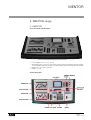
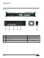
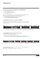
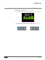
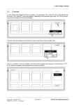
MENTOR
MENTOR
System Manual
Issue 1.0
Lighting Technologies
Lighting
Technologies
ME
1103
Page
1
Issue
:
001
1106.01.103
MENTOR
Page
2
Issue : 001
Lighting Technologies
MENTOR
INDEX
1 Introduction
1.1 Delivery and Unpacking
1.2 Preparing the Desk Location
1.3 Desk Installation
1.4 Power Supply
1.5 Electrical Connection
Lighting Technologies
5
5
5
5
6
6
2 The MENTOR range
2.1 MENTOR
2.1.1 Technical specifications
2.1.2 Front panel
2.1.3 Rear panel
2.2 EXTENSION Wing
2.2.1 Technical specifications
2.2.2 Rear panel
2.2.3 Addressing an EXTENSION
2.2.4 Interconnections between MENTOR and EXTENSION WING(S)
2.2.5 EXTENSION using the power supply of the MENTOR
2.2.6 EXTENSION using its built-in 230 V power supply
7
7
7
7
8
10
10
10
11
12
12
12
3 ISIS SOFTWARE
3.1 Getting upgrades via the Internet
3.1.1 ISIS+ Pages
3.1.2 Main downloads
3.2 Installing and upgrading ISIS®
3.2.1 Upgrading ISIS® with an external CD-ROM device
3.2.2 Upgrading ISIS® with an USB Memory Pen
3.3 Configuration
14
14
14
15
15
15
16
17
4 Additional sources of information
18
Page
3
Issue : 001
MENTOR
Page
4
Issue : 001
Lighting Technologies
MENTOR
1. Introduction
1.1 Delivery and Unpacking
As soon as you receive your equipment, open the boxes and inspect the items received. If you
discover any damage, contact the carrier immediately and make any necessary claim for the
problems discovered. You can be sure that when the equipment left our factory it was in perfect
condition. Check that the equipment supplied to you corresponds to the consignment note and
that this corresponds to your order. You will find the references of your desk on an identification
label affixed to the rear panel. If there is any discrepancy in the order and delivery, contact your
supplier immediately who will clarify the situation to your full satisfaction.
Permissible storage conditions:
Temperature
Relative humidity
: -10 to +50° C
: variation rate: 20 °C/hour
: 20 to 80 % without condensation.
1.2 Preparing the Desk Location
The surface on which desk is to be located, should be smooth, level and sturdy.
Make sure that there is enough clearance around the desk to :
• open the desk
• access the rear connections
• allow air circulation around vents to prevent the desk from over-heating.
1.3 Desk Installation
The MENTOR desks is a professional lighting console with memory, it is Class I equipment
designed and manufactured to the EN 60950 standard.
THIS EQUIPMENT MUST BE EARTHED.
No special provisions need to be made for the installation of the equipment. The room in which
the equipment is to be installed must be clean, dust-free and have a temperature between
5 °C and 35 °C and a relative humidity from 20 to 80 % without condensation.
Consumption of food and drink over the desk is inadvisable to avoid waste being accidentally
dropped into the equipment and impairing certain functions.
The lighting desk and the monitor should be installed on a table or a console. Like all equipment
which includes microprocessors and uses similar technology, the desk is sensitive to the
influences of static electricity and it is possible that these influences will affect functioning in
certain circumstances. If this is the case, it will be necessary to place anti-static carpets on
the floor and perhaps to make the atmosphere more humid. Whenever a carpet is to be used,
it must be an antistatic carpet.
In order to avoid wasting time and possibly damaging the equipment, the installer is invited to
scrupulously follow the instructions in the diagrams shown, and on the rear panel of the ISIS®
based desk.
Before powering up the desk or any of its peripherals, check that the voltages are within the
limits defined in the TECHNICAL SPECIFICATIONS paragraph.
Note: all connections should be made with the power turned Off, otherwise functioning may
be affected and can even damage the equipment under certain conditions.
Lighting Technologies
Page
5
Issue : 001
MENTOR
1.4 Power Supply
Like all equipment used in computer systems, your system is sensitive to the characteristics of
the mains network and in particular to variations and voltage peaks.
Consequently, we advise you to use an appropriate line conditioner on this equipment.
Please consult us if you are in any doubt about this.
The line is to be protected by fuse or by circuit breakers and is to be provided with an earth
connection for personal safety.
Important Notice for Power Cables
Power cables and connectors are an important part of your equipment and contribute to its
safety.
Always use the connector to make or interrupt the link; never pull on the cable.
Do not damage the cable or the connectors in any way; do not pinch or tie together power
supply and signal cables, check them at each installation and at regular intervals on a
permanent installation.
1.5 Electrical Connection
TO PREVENT THE RISK OF ELECTRIC SHOCK, DO NOT OPEN THE DESK. ACCESS TO
INTERNAL PARTS IS NOT REQUIRED FOR NORMAL OPERATION. THERE ARE NO USER
SERVICEABLE PARTS WITHIN. REFER SERVICING TO QUALIFIED ENGINEERS ONLY.
LETHAL VOLTAGES ARE PRESENT INSIDE!
ALWAYS DISCONNECT FROM THE POWER SUPPLY BEFORE OPENING FOR
INSPECTION.
PHOENIX and MENTOR ranges of lighting consoles are professional lighting control systems
developed with simplicity of use in mind. In order to maintain the proficiency of the built in safety
features, this equipment shall be installed and maintained by qualified service personnel only.
Page
6
Issue : 001
Lighting Technologies
MENTOR
2. MENTOR-range
2.1 MENTOR
2.1.1 Technical specifications
•
•
•
•
Power supply: 230 V +/- 14% - 50 Hz
The ID label of the console is found on the inside and outside of the bottom panel.It includes
the Part Number (1AX xxx xxx xxx), the serial number, the rated voltage, the CE marking.
Dimensions: 775 x 450 x 130 mm
Weight: 13.3 kg
2.1.2 Front panel
Lighting Technologies
Page
7
Issue : 001
MENTOR
2.1.3 Rear panel
1
AUDIO IN
XLR3 F
2
LINK TO MENTOR EXTENSION WINGS
DB 15 F
3
EXTERNAL CONTROL LINES
DB 9 F
4
DMX 1 OUT
XLR5 F
5
DMX 2 OUT
XLR5 F
6
POWER SUPPLY FAN, POWER SUPPLY SWITCH
Page
8
Issue : 001
Lighting Technologies
MENTOR
8
MOUSE PORT
9
PARALLEL PORT
10
LAN ETHERNET PORT
11
SERIAL PORT EIA/RS-232
12
KEYBOARD PORT
13
SVGA MONITOR OUTPUT
14
NOT USED
15
NOT USED
16
USB PORTS
17
NOT USED
18
START BUTTON
Lighting Technologies
Page
9
Issue : 001
MENTOR
2.2 EXTENSION Wing
2.2.1 Technical specifications
•
•
•
•
Power supply: 230 V - 50/60 Hz
The ID label of the console is found on the inside and outside of the bottom panel.It includes
the Part Number (1AX xxx xxx xxx), the serial number, the rated voltage, the CE marking.
Dimensions: 380 x 450 x 130 mm
Weight: 4.7 kg
2.2.2 Rear panel
1
EXTENSION LINK IN
DB 15 M
2
EXTENSION LINK OUT/THRU
DB 15 F
3
POWER SUPPLY
Page 10
Issue : 001
Lighting Technologies
MENTOR
2.2.3 Addressing an EXTENSION
Each MENTOR can be extended with up to 4 EXTENSION Wings. Each of the Wings has its
own address. The address is set by way of jumper inside the EXTENSION wing. The factory
setting for each Wing is address 1.
In case that more than one Wing is connected to a MENTOR it is necessary to configure the
address.
Selecting the address of the Wing
1. Remove the screw on the bottom panel, and open the Wing.
2. The Pin header to address the Wing is placed on the front pcb board. The pin header is
below the 26 pin connector.
3. The sketches below show the different settings for each possible wing address. Left to
right: wing address 1, address 2, address 3 and address 4.
Lighting Technologies
Page
11
Issue : 001
MENTOR
2.2.4 Interconnections between MENTOR and EXTENSION WING(S)
Each wing is standard delivered with:
• an ‘extension link’ cable of 1.5 m
• a set of selfs-adhesive numbering labels
• a power supply cable (230 V)
Up to two EXTENSION WINGS can receive their dc supply voltage from the MENTOR, via the
Extension Link cable. Each Wing is fitted with a built-in 230 V power supply.
The two paragraphs below describe how to link the EXTENSIONS:
• one or two EXTENSIONS supplied by MENTOR
• EXTENSIONS using their built-in 230 V power supply
2.2.5 EXTENSION using the power supply of the MENTOR
Only possible in case if using up to 2 wings with the standard extension link cable (delivered with
Extension). For any other configuration, please refer to paragraph ‘Extension using its built-in
230 V power supply’.
2.2.6 EXTENSION using its built-in 230 V power supply
Use of the built-in power supply is mandatory:
• when you use an Extension cable longer than 1.5 m
• when you connect more than 2 wings to one MENTOR. Use of the built-in power supply
is then mandatory for the third and fourth Extension (irrespective of cable length).
The factory setting for each Wing is: External power supply ON, ready to be supplied from a
MENTOR. Built-in supply set to Off.
(Note: the built-in power supply will not supply dc to other Wings).
Page 12
Issue : 001
Lighting Technologies
MENTOR
Enabling the external Power supply:
1. Remove the screw on the bottom panel, and open the Wing.
2. The Pin header to select the dc power source address is placed on the bottom pcb board.
3. The sketch below gives the settings for the power supply. Left to Right: built-in 230 V
power supply; external dc power supply (factory default setting).
Lighting Technologies
Page
13
Issue : 001
MENTOR
3. ISIS® Software
The ISIS® software for MENTOR and PHOENIX/XT is distributed via the internet or on a CDROM.
3.1 Getting upgrades via the Internet
The ISIS® support page can be reached via ADB’s website: www.adblighting.com > ADB
Products > Control desks > ISIS® software > ISIS® support website. The current shortcut is
http://www.adbttv.dyndns.org but this may change. On the ISIS® Support pages you will find
the latest release (and some earlier ones) of ISIS® and related programs.
For MENTOR please select the ISIS+ pages (ISIS+ = ISIS® 2.0 and later).
3.1.1 ISIS+ Pages
On this page you can find the latest released version of ISIS® and related programs.
Page 14
Issue : 001
Lighting Technologies
MENTOR
3.1.2 Main downloads
•
•
•
Full ISIS® CD : FullxxxPxxx.ISO (ISO.CD image)
ISIS® for USB Stick
ISIS® translator
3.2 Installing and upgrading ISIS
This chapter will describe two upgrade methods
• by means of a CDR (requires external CD Reader)
• by means of a USB Memory Pen
3.2.1 Upgrading ISIS® with an external CD-ROM device
Required equipment
• a Windows PC with CD writer; a CD writer program and floppy drive
• a external USB CD-ROM device a empty CD-ROM and
Preliminary action – download files
Download the most recent versionof ISIS: FullxxxPxxx.ISO
Save it on the hard disk.
Step 1:
find the downloaded file BOOTUSBdev.exe
Burn the ISIS CD.
Step 2:
find the downloaded file BOOTUSBdev.exe on the ISIS® CD
run (execute) BOOTUSBdev.exe
Second we’ll install the software on the MENTOR
Step 3: save your current show
Step 4:
shut the MENTOR down and switch power off the mains
Step 5:
on MENTOR: insert the floppy disk.
Connect the USB CD-ROM reader; place the ISIS CD
Step 8:
start up the MENTOR
Step 9:
when you get a message
= = = = = = = = = =
= =
Connect the
= =
Press enter
= = = = = = = = = =
press ENTER.
= = = = = = = = = = = = =
target device to USB port
to continue
= = = = = = = = = = = = =
=
=
=
=
Step 10: installing software upgrade(s)
inslin
setup
upgrades Linux; this is not always necessary; see paragraph
Configuration.
upgrades the ISIS® software
The final touch
Step 11: once the setup is done, remove the Boot floppy and the USB CD-ROM.
Restart the MENTOR.
Lighting Technologies
Page
15
Issue : 001
MENTOR
3.2.2 Upgrading ISIS® with an USB Memory Pen
Required equipment
• a Windows PC with floppy drive and USB port; with an unzip programme (WinZip, StuffIt,
or similar)
• a USB memory pen, formatted with FAT or FAT32.
• Note: to verify the formatting
→ Insert the USB memory pen in the PC
→ In My computer: select (highlight) the Memory Pen (single left-click)
→ Right-click > Properties > TAB: General
Preliminary action – download files
Download the most recent versions of USB_ISIS.zip and bootUSBdev.exe
Save them on the hard disk (or burn them on a CDR).
First we’ll create a Boot floppy.
Step 1: find the downloaded file BOOTUSBdev.exe
run (execute) BOOTUSBdev.exe
Step 2:
follow the instructions on the pop-up menu.
You have now created the Boot floppy. You can keep it for use with later upgrades
with USB devices.
Second we’ll prepare the USB memory pen
Step 3: in the USB memory pen, create a directory USB_ISIS
Step 4:
find the downloaded file USB_ISIS.zip
unzip (unpack) it
copy all the unzipped files to the memory pen, in the directory
USB_ISIS
Third we’ll install the software on the MENTOR
Step 5: Save your current show
Step 6:
shut the MENTOR down and switch power off the mains
Step 7:
on MENTOR: insert the floppy disk. Don’t insert the USB memory pen yet.
Step 8:
start up the MENTOR
Step 9:
when you get a message
= = = = = = = = = = = = = = = = = = = = = = =
= =
Connect the target device to USB port
= =
Press enter to continue
= = = = = = = = = = = = = = = = = = = = = = =
then insert the USB stick and press ENTER.
=
=
=
=
=
=
=
=
=
=
=
=
Step 10: installing software upgrade(s)
What should you install?
inslin
setup
upgrades Linux; this is not always necessary; see paragraph
Configuration.
upgrades the ISIS® software
The final touch
Step 11: once the setup is done, remove the Boot floppy and the USB pen.
Restart the MENTOR.
Page 16
Issue : 001
Lighting Technologies
MENTOR
3.3 Configuration
After LINUX and ISIS® are installed, ISIS® automatically boots after a power up into the Setup
program.
If there are no hardware changes or extra channels, you do not need to do anything in the setup.
If you have changes, you need to initialize these changes in the appropriate part of the Set-up
program.
After the configuration, select <SAVE and EXIT>; the system will automatically reboot.
Lighting Technologies
Page
17
Issue : 001
MENTOR
4. Additional sources of information
This MENTOR System Manual does not describe ISIS®, the common software for MENTOR
and PHOENIX/XT:
You’ll find “everything you always wanted to know about ISIS®” in:
An introduction tot ISIS® 2.1x.
This short form User Manual for ISIS® 2.1x can be downloaded from the ADB website.
www.adblighting.com > ADB Products > Control Desks > ISIS® Software > Introduction to
ISIS® 2.1x.
The User Manual for ISIS® 2.10.
The comprehensive User Manual for ISIS® 2.1x can be downloaded from the ADB website.
www.adblighting.com > ADB Products > Control Desks > ISIS® Software > ISIS® 2.1x User
Manual.
The ADB Ethernet Network Guide
The “ADB Ethernet Network Guide” can be downloaded from the ADB website.
www.adblighting.com > ADB Products > Interfaces > Ethernet > select the User Manual.
The Wi-Fi Remote User Manual
The “User Manual for Wi-Fi Remote” can be downloaded from the ADB website.
www.adblighting.com > ADB Products > Interfaces > Wi-Fi Remote Control > select the User
Manual.
The HF Remote User Manual
The “ User Manual for the HF Remote” can be downloaded from the ADB website.
www.adblighting.com > ADB Products > Interfaces > HF Remote Control > select the User
Manual.
ESTA and its Technical Standards Programme
Learn more about - or participate in - the ongoing standards development efforts:
http://www.esta.org/tsp
Example: the ESTA Control Protocols Working Group covers subjects such as
DMX512-A the successor to DMX512/1990
RDM Remote Device Management (EIA-485 serial transmission)
ACN Advanced Control Network (over Ethernet).
The process of creating a new standard includes one or several Public Reviews.
Participate!
Page 18
Issue : 001
Lighting Technologies
MENTOR
Lighting Technologies
Page
19
Issue : 001
M-1103-E-11h
MENTOR
Subject to modifications
Belgium
N.V. ADB-TTV Technologies S.A.
(Group Headquarters)
Leuvensesteenweg 585,
B-1930 Zaventem
Tel : 32.2.709.32.11
Fax : 32.2.709.32.80
E-Mail : [email protected]
Deutschland
ADB GmbH
Dieselstraße 4,
D-63165 Mühlheim am Main
Tel : 49.6108.91.250
Fax : 49.6108.91.25.25
E-Mail : [email protected]
France
ADB S.A.S.
Sales office:
168/170, boulevard Camélinat
F-92240 Malakoff
Tel : 33.1.41.17.48.50
Fax : 33.1.42.53.54.76
E-Mail : [email protected]
Factory & group logistics centre:
Zone industrielle Rouvroy
F-02100 Saint-Quentin
Tel : 33.3.23.06.35.70
Fax : 33.3.23.67.66.56
E-Mail : [email protected]
ADB - Your Partner for Light - ISO 9001 : 2000 certified
Lighting Technologies
www.adblighting.com
Page 20
Issue : 001
Lighting Technologies