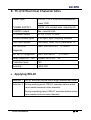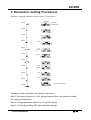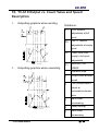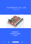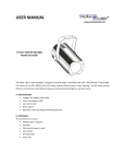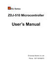
1
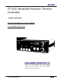
TC-610 Ultrahigh Precision Tension
Controller
USER MANUAL
Concise Solution by easy-setting
of material thickness
TAIPEI - TEL : 886-2-28221466 FAX : 886-2-28238003
CHINA - TEL : 86-21-69153366 FAX : 86-21-69153939
Email:[email protected]
TC-610 USER MANUAL
第0頁
Table of Contents
1.
TC-610 Features.................. 2
2.
Safety precautions
3.
Control Panel Functions.............. 3
4.
External Dimensions and Fastening Positions ... 4
5.
Terminal Connection Diagram......... 5
6.
Parameter Contents & Definitions....... 6
7.
TC-610 Parameter Table............ 7
8.
TC-610 Electrical Characteristics ........ 8
9.
TC-610 Parameters Setting Procedures.... 9
10.
Output vs. Count Value and Speed Description.. 10
TC-610 USER MANUAL
2
第1頁
1. TC-610 Features
TC-610 is a powerful, easy-to-use tension controller. From the control
panel, the user simply sets the tension to FULL spool and EMPTY spool,
and enters either total material length or total number of circles to
achieve high precision tension control.
Applications: applies to industries such as plastic, thin film, gluing, electric cord, steel
plate, starching yarn, joining warp, and paper.
2. Safety precautions
¾ Make sure to power off before wiring or unwiring TC-610 to avoid
danger or causing damage to controller.
¾ Terminals 3 and 4 of outputting 0-24V DC voltage is only used for
resistive load, not for inductance load (DC motor).
¾ Terminals 11-25 are contacts for inputting and outputting signals. Do
not connect them to AC power to avoid damage.
¾ Terminals 1 and 2 are input points for AC28V±2V. Use isolated
transformer for power supply.
¾ Terminals 3 and 4 are for outputting 0-24V DC voltage (max. 5.5A).
Put in fuse circuit before connecting to load.
¾ Do not remove controller casing or perform pressure tests to
controller components.
¾ Keep records of TC-610 tension controller parameter setting after
test run.
TC-610 USER MANUAL
第2頁
3. Control Panel Functions
1 2
3
6
4
7
5
Control Panel Functions:
1
Count value display 5/8” RED LED, 6 Digit
2
Count setting display 1/2” GREEN LED, 6 Digit
3
RUN
Operation indicator
PRG
Entry parameter indicator/limit signal input
synchronization indicator
ERR
MODE
▲
4
RELAY output indicator
Entry parameter key/exit parameter key
Addend input key (count/parameter
change/parameter modification)
▼
Subtrahend input key (count/parameter
change/parameter modification)
5
6
7
SET
ENTER key after parameter modification
LOAD
Press this key to view final tension output
RESET
Count number reset and tension output reset
Indicating tension output 5/8” RED LED, 3 Digit
FULL
EMPTY
TC-610 USER MANUAL
Full spool tension setting knob
Empty spool tension setting knob
第3頁
4. External Dimensions and Fastening Positions
1
ACTUAL
DIA
EMPTY
DIA
THICKNESS
mm
盤面開孔 L:196mm x H:76mm
Panel cut-out
TC-610 USER MANUAL
第4頁
近接PR
5. Terminal Connection Diagram
Terminal #
1
2
3
4
5
6
7
8
9
10
11
12
13
14
15
16
17
18
19
20
21
22
23.24.25
TC-610 USER MANUAL
Description
Contents
AC 28V±2V INPUT
MAX 6A
TO magnetic powder
brake/clutch
DC 0-24V OUTPUT
AC220±10% INPUT
FG 3rd ground wire
C
RELAY
A
output: 250V
AC、1A
B
+
D/A OUTPUT
-
+12V
Limit switch
IN
input
OV
0-10V
A/D INPUT
OV
+12V
DCV
Control input
COM
common point
START Initiating input
Emergency
E.STOP
stop
Roller
RESET
diameter reset
Reserved
Power input
C
A
B
⊥
○
○
○
○
0-10VDC
50Hz/2KHz
Master speed 0-10V DC
MAX. 100Ma
19
20
21
○
○
○
○
22
○
○
第5頁
6.TC-610 Parameter Contents and Definitions
Parameters
Definition
Pr01
Maximum outer diameter: full spool (9999mm),
Ex-factory setting: 600mm
Pr02
Minimum outer diameter: empty spool (0000mm),
Ex-factory-setting: 95mm
Pr03
Password, Ex-factory setting: 1234
Pr04
Pulse rate(PPR) amount per turn, Ex-factory setting: 1
Pr05
Compensated delay time for master speed input (Sec.)
Pr06
Tension compensated percentage on acceleration (%)
Pr07
Tension compensated percentage on decelerating (%)
Pr08
Tension compensated percentage at urgent stop (%)
Pr09
Tension compensated percentage at stop (%)
Pr10
Wind / Unwind Control Mode (1: Unwind 2: Wind)
Pr11
Max. Percentage for Brake output modification (%)
Pr12
Signal input frequency (0: 50Hz ; 1: 2KHz)
Pr13
Alarm point setting. There will be an inform before the actual
value meets Full spool value.
Pr14
Decimal point setting of Thickness unit (2:0.01mm 3:0.001mm)
Pr15
Invert function of Pr06
0:positive direction 1: opposite direction
Pr16
Invert function of Pr07
0:positive direction 1: opposite direction
Pr17
Invert function of Pr08
0:positive direction 1: opposite direction
Pr18
Invert function of Pr09
0:positive direction 1: opposite direction
TC-610 USER MANUAL
第6頁
7.TC-610 Parameter Table
Parameter
number
Definition
Unit
Range
Factory
Setting
Pr01
Maximum outer diameter
mm
0000-9999
600
Pr02
Minimum outer diameter
mm
0000-9999
95
Pr03
Password
Digit
0000-9999
1234
Pr04
Signal sum per turn
PPR
0001-9999
100
Sec.
0.1- 25.5
0.1
Pr05
Compensated delay time for
master speed input
%
000-100
0
Pr06
Tension compensated
percentage on acceleration *
%
000-100
0
Pr07
Tension compensated
percentage on decelerating *
%
000-100
0
Pr08
Tension compensated
percentage at urgent stop
%
000-100
0
Pr09
Tension compensated
percentage at stoppage
Pr10
Wind/unwind control mode
1: Unwind 2: Wind
0,1
1
Pr11
Tension modified factor(K)
%
000-999
0
Pr12
Signal input frequency
0: 50Hz ; 1: 2KHz
0,1
0
mm
000-999
0
Pr13
Initial value for Full spool
(D)/empty spool (d)
2:0.01mm
3:0.001mm
2,3
2
Pr14
Thickness unit
(Decimal point setting)
Pr15
Invert function of Pr06**
0,1
0
Pr16
Invert function of Pr07**
0,1
Pr17
Invert function of Pr08**
0,1
0:positive
direction
1: opposite
direction
Pr18
Invert function of Pr09**
0,1
* Winding master motor accelerating VOUT=V × (100% + ?%)
Unwinding master motor accelerating VOUT=V × (1 - ?%)
** Winding master motor accelerating VOUT=V × (100% - ?%)
Unwinding master motor accelerating VOUT=V × (1 + ?%)
TC-610 USER MANUAL
0
0
0
第7頁
8. TC-610 Electrical Characteristics
Power input
AC220V ±10% 50/60Hz consumption
power 15W
POWER SUPPLY
AC28V ±2V current max. capacity 6A
0-24VDC output
Max. current 5.5A
DC power output
DC12V ±0.2V 110mA
Control contact input
NPN input, optic coupling isolated
CLK count speed
50Hz/2kHz Note: set in parameter 12
D/A OUTPUT
12BIT D/A OUTPUT 0-10VDC
diagnosis
A/D INPUT diagnosis
10BIT A/D INPUT
0-10VDC
Relay output R1、R2
Contact 250V AC、1A
Protection level
IP40
Humidity
0-95% RH
¾ Applying RELAY
Selection 1 RELAY executes before count length reaches set value.
Selection 2 During winding period, RELAY executes before actual
value meets maximum outer diameter.
During unwinding period, RELAY executes before actual
value meets minimum outer diameter.
TC-610 USER MANUAL
第8頁
9.Parameters Setting Procedures
Example: Changing Parameter 4 from 1.00 to 3.00 as follows:
Indicator
PRESS
RED LED
GREEN LED
PRESS
PRESS
PRESS
Flash
PRESS
Flash
OR
Note 2)
PRESS
Note 1)
PRESS
OR
PRESS
Flash
Note 3)
PRESS
Flash
Flash
PRESS
PRESS
Back to normal display
Changes to other parameters are similar to the above.
Note 1: Ex-factory password is 1234. Wrong password won’t be allowed to modify
the content of Parameters.
Note 2: Change parameter when Prxx on red LED flashes.‧
Note 3: Confirm by pressing SET after parameter change.
TC-610 USER MANUAL
第9頁
10. TC-610 Output vs. Count Value and Speed
Description
1.
Outputting graphics when winding.
②
①
Notations:
A1
FULL tension
(adjustable) at full
spool
A0
EMPTY tension
(adjustable) at empty
③
spool
④
主
馬
達
速
度
⑤
Count value from
empty to full spool
(adjustable)
時間
2.
CF
V1
Outputting graphics when unwinding.
①
MAIN MOTOR
SPEED
t
Operation time
1
Output curve at fixed
speed
②
2
Post-compensation
output at
acceleration/deceler
④
ation
③
⑤
主
馬
達
速
度
3
Main motor
accelerating
時間
4
Speed locking
5
Main motor
decelerating
TC-610 USER MANUAL
第 10 頁