1
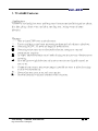
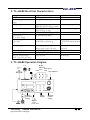
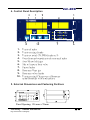
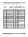
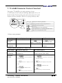
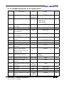
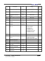
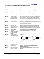
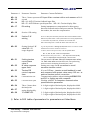
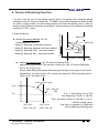
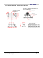
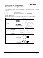
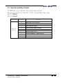
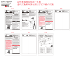
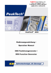
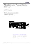
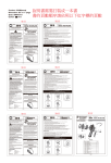
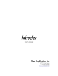
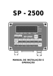
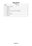
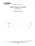
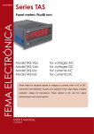
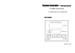
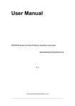
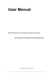
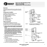
D:\80G\My Documents\2004-11-30\新資料夾\李佳芬\說明書\TC-6068E(英文).doc
TC-6068E
High Accuracy Tension Controller
USER MANUAL
TAIPEI - TEL : 886-2-28221466 FAX : 886-2-28238003
CHINA - TEL : 86-21-69153366 FAX : 86-21-69153939
Email:[email protected]/[email protected] (China)
Chih Horng - TC6068E User Manual
Eng. Version 95.01.17 (Original)
第0頁
D:\80G\My Documents\2004-11-30\新資料夾\李佳芬\說明書\TC-6068E(英文).doc
Index
1.
TC-6068E Features.................. 2
2.
TC-6068E Electrical Characteristics........ 3
3.
TC-6068E Operation Diagram.............. 3
4.
Control Panel Description................. 4
5.
6.
External Dimensions and Fastening
4
Positions
Terminals Connection Diagram and Details. 5
7.
TC-6068E Parameter Clusters Flowchart.. 6
8.
TC-6068E Pr.01 Cluster Explanation.... 7
9.
Tension Diminishing Function............. 11
10.
Tension Detector Device and Checkup..... 12
11.
Principles for Outer Diameter Calculation
13
and Setting Preset Value
Relay Operation.................. 14
12.
Chih Horng - TC6068E User Manual
Eng. Version 95.01.17 (Original)
第1頁
D:\80G\My Documents\2004-11-30\新資料夾\李佳芬\說明書\TC-6068E(英文).doc
1. TC-6068E Features
Applications:
TC6068E is an ultrahigh accuracy feedback control system specifically designed for plastic,
thin film, gluing, electric wire, steel plate, starching yarn, joining warp, and paper
industries.
Features:
一、
二、
三、
四、
五、
六、
七、
八、
九、
Easy-to-input COSθ curve tension decrease.
Tension feedback control stops performing mathematical calculations at shutdown.
Possessing DC24V, 3A power for magnetic powder driver.
Possessing unique start-up, acceleration/deceleration, emergency stop, and
compensation functions.
Its unique manual/automatic control mode shifting function prevents vibrations from
occurring.
Structural gross weight deduction and tension correction are digitally entered for
ease of use.
Command-type contact point output makes it possible for users to tailor the settings
to their own requirements.
Powerful features, easy to use, and cost-effective.
Password protected with fixed numbers avoids confusion.
Chih Horng - TC6068E User Manual
Eng. Version 95.01.17 (Original)
第2頁
D:\80G\My Documents\2004-11-30\新資料夾\李佳芬\說明書\TC-6068E(英文).doc
2. TC-6068E Electrical Characteristics
AC220V ±10% 50/60H2
100W max.
DC-12VDC±5% 100mA
Voltage
Power
Encoder/Limit Switch power
supply
Encoder input
A A/B phase(difference 90°)
Resonance frequency 10K Hz
NPN input photo coupling isolated
NPN input
Resonance speed 50Hz/Sec
photo coupling isolated
NPN input photo coupling isolated
DC-10V±0.5VDC 80mA
Shaft Limit Switch input
Control contact input
Tension detect
EXG power supply
Tension detector
signal input
0-20mVDC
0-30mVDC for 250/450 kg
Specifications
5.10.20.30.50.100.250KG.450
KG
Tension input:12 Bit A/D
DC:0-20mV
Master speed input:12 Bit A/D
DC:0-10V
Tension control output D/A 12 Bit DC:0-10V
A/D input analysis
D/A output analysis
Relay output
a contact 250V AC,
3.0A, DC 24V
Magnetic powder brake/
clutch control electric current
≦1A
PWM output
3. TC-6068E Operation Diagram
Roller
diameter
reset Emergency
Start
Stop Auto/Manual
Motor
Tension
input
TC6068E
AUTO
PV
MANU
SV
CH-SYS
Tension
parameter
setting
Status
display
Manual
tension
setting
Magnetic
powder
brake/clutch
Chih Horng - TC6068E User Manual
Eng. Version 95.01.17 (Original)
第3頁
D:\80G\My Documents\2004-11-30\新資料夾\李佳芬\說明書\TC-6068E(英文).doc
4. Control Panel Description
3
1
9
5
4
8
1.
2.
3.
4.
5.
6.
7.
8.
9.
10.
10
7
6
Tension display
Tension setting display
Tension unwind (TAPER) display at %
Outer diameter/output/tension decrement display
Auto/Manual shift key
Manual input of basic value
Status display
Parameter Enter key
Parameter value display
Tension setting/Changeover of Parameter
items/Parameter value modification
5. External Dimensions and Fastening Positions
TC6068E
AUTO
PV
MANU
SV
CH-SYS
Panel Opening: 196 mm x 70mm
Chih Horng - TC6068E User Manual
Eng. Version 95.01.17 (Original)
第4頁
D:\80G\My Documents\2004-11-30\新資料夾\李佳芬\說明書\TC-6068E(英文).doc
6. Terminals Connection Diagram and Details
TP2
TP3
TP4
近接
TP1
Terminal #!
TP1
Terminal #
1
DC power input 3V (+24V)
2
DC power input 3V (-0V)
2
3
Magnetic powder brake/clutch
control output (+24V)
Magnetic powder brake/clutch
control output (-0V)
3
Power for encoder/limit switch
+12V ≦50mA
Power for encoder/limit switch
-0V ≦50mA
Encoder input channel A
4
Encoder input channel B
4
TP2
!
1
2
3
4
5
6
TP4 1
2
3
4
Power input AC220V 50/60Hz
Power input AC220V 50/60Hz
FG ground wire
A/D input master speed simulate
DC 0-10V
D/A out put tension control
0-10V
COM for A/D D/A out 0V
EXG+ (green) tension transducer
input
EXG- (black) tension transducer
input
SIG+ (red) tension transducer
contact
SIG- (white) tension transducer
contact
Chih Horng - TC6068E User Manual
Eng. Version 95.01.17 (Original)
TP3
1
5
6
7
8
9
Shaft limit switch signal input
COM for control signal
Control input RUN
Emergency stop
RESET
10
11
Reserved
12
Relay output contact 250V≦
1A
Relay output contact 250V≦
1A
13
Reserved
第5頁
D:\80G\My Documents\2004-11-30\新資料夾\李佳芬\說明書\TC-6068E(英文).doc
7. TC-6068E Parameter Clusters Flowchart
Description: TC-6068E has two major parameter clusters.
A: Pr. 01 Items: Various functions adjusting parameters no.01-no.36
B: Pr. 02 Items: Tension zeroing and tension correction no.01-no.02
Relevant keys and prompts as follows on entering parameter mode:
TC6068E
紅色LED
AUTO
PV
MANU
display the content of parameter
Red LED
綠色LED SV
Green LED display parameter cluster and parameter no.
CH-SYS
parameter enter (set) mode
enter parameter no. and value input
select parameter no. or modify parameter value
light on as enter parameter mode
1. How to enter parameter
Panel display!
General display value
Operation
method
Mode
explanation
Parameter cluster no.
Pr. Cluster item no.
press
one time
Select parameter no.
press
one time
Select
item no.
Pr.Cluster
2. How to modify parameter (Pr. Cluster) value
Panel display!
Parameter cluster no.
Mission
explanation
How to modify the value of How to modify the value of Pr.
parameter no.
Cluster item no. (Pr01, Pr02)
Operation
method
1 press
to select the parameter no.
that will be modified
2 press
one time to display its value
Pr. Cluster item no.
1 press
to select the pr. Cluster item no.
that will be modified.
2 press
one time to display its value (content)
3 press
to modify the value
(content)
3 press
to modify the value
4 press
4 press
back to parameter selection mode
Chih Horng - TC6068E User Manual
Eng. Version 95.01.17 (Original)
back to pr. Cluster selection mode
第6頁
D:\80G\My Documents\2004-11-30\新資料夾\李佳芬\說明書\TC-6068E(英文).doc
8. TC-6068E Parameter Pr.01 Explanation
Pr. 01 item
no.
Description
Unit
Range
Factory
Setting
0-255
3
NO—01
Irresponsive area
1Dight
kg/N/LB
NO—02
Execution mode
1, 2, 3
NO—03
Tension unwind (TAPER)
percentage
NO—04
Password protected access
NO—05
Min. outer diameter (empty
spool diameter)
NO—06
NO—07
1: fixed tracking
2: SPAN decay
3: curve decay
%
3
0-50%
10
0-9999
1234
mm
0000-9999
100
Max. outer diameter (full
spool diameter)
mm
000-999
1000
Encoder pulse input setting
selection
1, 2
NO—08
Signal length in encoder
mm
0.001-9.999
0.300
NO—09
Spool limit input per rotation
P/R
1-100
1
NO—10
Tension reduction percentage
at stoppage
%
0-100%
10%
NO—11
Tension control output
compensation percentage at
emergency stop
%
0-100%
10%
NO—12
Wind/unwind selection
NO—13
Tension average frequency
0.01 Sec./Time
1-200
10
NO—14
Master speed average
frequency
0.01 Sec./Time
1-200
20
NO—15
Panel tension display average
frequency
0.01
1-200
50
2
1: Single channel pulse
2:AB channel pulse (difference 90 degrees)
0, 1
0: wind
1: unwind
0
Sec./Time
NO—16
PK setting
K
0.00-99.99
1.00
NO—17
IK setting
Sec.
0.00-99.99
10.00
NO—18
Section 2 IK value
Sec.
0.00-99.99
3.00
NO—19
Section 2 difference for usage
diagnosis
1 Digit
kg/N/LB
1-9999
50
Chih Horng - TC6068E User Manual
Eng. Version 95.01.17 (Original)
第7頁
D:\80G\My Documents\2004-11-30\新資料夾\李佳芬\說明書\TC-6068E(英文).doc
Pr.01 item
no.
Description
Unit
Range
Factory
Setting
NO—20
Min. error for I replace
1 Digit
kg/N/LB
1-9999
1.00
NO—21
Max. error for I replace
1 Digit
kg/N/LB
1-999
100
NO—22
Accumulation start base
voltage
VDC
0.00-10.00
1.00V
NO—23
Upper Limit for I react value
VDC
00.0-10.0
10.00
NO—24
PID execution time
Sec.
0.01-2.55
0.05
NO—25
Upper limit for tension
feedback
1 Digit
kg/N/LB
0000-9999
1000
NO—26
Lower limit for tension
feedback
1 Digit
kg/N/LB
0000-9999
50
NO—27
Specified output method for
RELAY 1
NO—28
Master speed input K value
NO—29
1-7
1=Start
2=Output OVER
3=Feedback HI
4=Feedback LOW
5=Feedback abnormal
6=Feedback normal
7=
Top row right side display
method
1-3
1: Outer diameter
2: Output percentage
3: Master speed input value
NO—30
Tension decimal point
0-3
NO—31
Tension setting value
1-9999
NO—32
Tension feedback K value
Tension feedback OFFSET
zero adjust
Hysteresis K value as per
accelerate or decelerate
Tension increase percentage
as accelerate
Tension decrease percentage
as decelerate
NO—33
NO—34
NO—35
NO—36
Chih Horng - TC6068E User Manual
Eng. Version 95.01.17 (Original)
7
0.001-9.999
±1000
1-1000
1-1000
1-1000
第8頁
D:\80G\My Documents\2004-11-30\新資料夾\李佳芬\說明書\TC-6068E(英文).doc
TC6068E Pr01 ParameterCluster Explanation
Pr.01 item no. Parameter Function
Parameter Content Definition
NO—01
Tension control
irresponsive area
This parameter shows preset tension. The digit is for
adjusting irresponsive range. Unit: Kg/N/LB
NO—02
Tension control
decrease setting
Tension decrease curve setting at winding. There are linear
and COSθ curve tension decrease methods. Refer to”9.
Tension Decrease Function Description” for detail.
NO—03
Tension control
tension decrement
percentage (empty
spool to full spool)
This parameter is preset at empty spool tension x (1-NO-03 setting %) =
NO—04
Access password
Factory setting: 1234. Access password has to be set at 1234 in order for
Pr01-NO05-38 parameters and parameters within Pr02 cluster to be
changed. Otherwise, items within parameter cannot be accessed to be
changed. This parameter is protected.
NO—05
Setting min. outer
diameter (empty spool)
NO—06
Setting max. outer
diameter (full spool)
Empty spool diameter input point. Tension unwinding and
speed control utilize the diameter as base calculation point.
Full spool outer diameter input point. Tension unwinding and
speed control utilize this value as final calculation point.
NO—07
Encoder input
selection
Length represented
by each signal in
encoder
Setting number of
pulse input by limit
switch per spool
rotation
0: single channel pulse input A or B channel
1: A/B channel (difference 90O) pulse input
NO—10
Setting tension control
output decrease
percentage at stoppage
NO—11
Setting tension output
At stoppage, TC-6068E calculated value can set
output percentage of D/A2 through this parameter
to avoid excessive stoppage tension.
Eliminating spool inertia on emergency stop.
NO—08
NO—09
full spool tension. E.g.: empty spool tension setting 10.00Kg, Pr01
parameter NO03 set at 30% with full spool tension of 7.00Kg(internally
calculated). Meantime, panel setting remains at 10.00Kg
Value set: 2
Roller
Value set: 1
Limit switch
Roller
compensation on e. stop
NO—12
Control mode
NO—13
Bias voltage of master
speed D/A2 output
Chih Horng - TC6068E User Manual
Eng. Version 95.01.17 (Original)
0: Wind 1: Unwind. Setting TC-6068E on Wind or
Unwind control mode.
Setting bias voltage of spool motor at base speed on
stoppage.
第9頁
D:\80G\My Documents\2004-11-30\新資料夾\李佳芬\說明書\TC-6068E(英文).doc
Parameter #
Parameter Function
NO—14
NO—15
NO—16
These 3 items represent A/D input filter constant with a unit measure of 0.01
second
NO—14 : A/D 1 Tension feedback input filter
NO—15 : A/D 2 Master speed input filter NO—16 : Tension display filter
PK setting
Setting instantaneous compensation for discrepancy
between feedback tension and preset tension. The larger
the number, the more the compensation.
Section 1 IK setting
NO—17
NO—18
NO—19
Section 2 IK
setting
Parameter Content Definition
IK is D/A 1 base point correction parameter when actual feedback tension
differs from preset tension. These 2 parameters are inversely proportionate,
i.e. the smaller the preset time, the faster the corrected time.
Note: Time setting of NO—19 must be smaller than that of NO—18.
NO—20
Setting Section 2 IK
value NO—19
usage diagnosis
E.g. Set this parameter to 50 Digit (5.0N) with tension set at 80.0N. Actual
feedback tension and its calculation as follows:
A: When (Actual value-preset value) < No—01 preset value
NO—17, NO—18, NO—19 do not compensate.
B: When (actual value-preset value) > NO—20 preset value (5.0N),
NO—17 compensates and perform NO—18 correction.
NO—21
NO—22
NO—23
Setting tension
control base
value %
IK value response
upper limit
Tension PID
control response
time
NO—24
Communication site
NO—25
Communication speed
NO—26
These 3 items show
decimal point
setting displayed by
TC-6068E LED.
NO—27
NO—28
This parameter is IK base value (D/A output start value),
i.e. each time after tension falls back, start performing
tension control calculation from this base value.
Setting max. range for IK correction to avoid
excessive tension control.
If set at 0.05 sec., tension actual feedback is read
and compared with preset value every 0.05 sec. to
perform tension control correction.
Communication address when initiating MODBUS PRU
and PLC or linking up with computer.
Working with PLC or computer communication
speed selection parameter.
0 : 0 digit to right of decimal point, displayed as 0000
1 : 1 digit to right of decimal point, displayed as 000.0
2 : 2 digit to right of decimal point, displayed as 00.00
3 : 3 digit to right of decimal point, displayed as 0.000
※ Refer to Pr01 table of parameters for parameters not listed here.
Chih Horng - TC6068E User Manual
Eng. Version 95.01.17 (Original)
第 10 頁
D:\80G\My Documents\2004-11-30\新資料夾\李佳芬\說明書\TC-6068E(英文).doc
9. Tension Diminishing Function
2. Setting Function
z Setting Decreasing Method: NO—02
within parameter Pr01.
Value [1]: Denoting no decrease function
Value [2]: Denoting diameter decrease method
Value [3]: Denoting COSθ decrease method
Value [4]: Denoting SINθ decrease method
Set start value as empty spool
1. To cope with the fact of decreasing tension due to increasing outer diameter during
winding process for most soft materials, TC-6068E is specifically designed to make it easy
for users to simply select the decreasing method and final decreasing rate in order to
perform desired tension decrease. According to expert analyses, the optimum decreasing
condition is COSθ angle.
Value [1]
Value [3]
Value [2]
Value [4]
Empty Spool Full Spool
z
DIA
Setting Decreasing Rate: NO—03 within Parameter Pr01.
Application requirement: This setting is valid only if NO—02 within Parameter
Pr01 is set at [2] or [3].
Preset value: Being the tension decreasing percentage from empty to full spool.
Explanation: If tension is set at 30, tension decreases by 30% at maximum spool
(refer to NO—06 within Pr01).
Panel tension setting
100%
Pr01‧NO—03
30%
70%
Min. spool
Pr01‧NO—05
E.g.: If decreasing rate is 30%
And beginning tension is 200.0N,
Then full spool tension is 200.0N x (1-0.3)
=140.0N (actual value)
Side view for assembly of 1040 Load
Max. Spool
Cell and Bearing including base
Pr01‧NO—06
Chih Horng - TC6068E User Manual
Eng. Version 95.01.17 (Original)
第 11 頁
D:\80G\My Documents\2004-11-30\新資料夾\李佳芬\說明書\TC-6068E(英文).doc
10. Tension detector Device and Checkup
Side view for assembly of 1040 Load Cell and
Bearing including base
Center line of bearing
including base
Bearing including base
Upper plate
Load Cell body
Base
Distance of fastening screws of
bearing on upper plate
hole dia. length
of bearing
A
Chih Horng - TC6068E User Manual
Eng. Version 95.01.17 (Original)
length
length
length
length
B
C
B1
C1
第 12 頁
D:\80G\My Documents\2004-11-30\新資料夾\李佳芬\說明書\TC-6068E(英文).doc
11. Principles for Outer Diameter
Calculation and Setting Preset Value
Outer diameter calculation for TC-6068E is based on the following equation to work out
diameter.
Encoder signal volume X Length represented by signal
Limit signal volume X 3.141593
Outer Diameter =
Setting preset value:
Relevant parameters are set within NO—07 NO—08 NO—09 of Pr01 parameter.
Pr01 item no.
Set value
1
NO—07
Channel A
pulse input
Channels A.B
2
NO—08
Function
difference90 degrees
Encoder
signal length
per number
L = 0.000
~2.000mm
L
1
Limit Switch 1
NO—09
2
Limit Switch 2
Chih Horng - TC6068E User Manual
Eng. Version 95.01.17 (Original)
第 13 頁
D:\80G\My Documents\2004-11-30\新資料夾\李佳芬\說明書\TC-6068E(英文).doc
12. Specifying Relay Output
TC-6068E has 2 sets of flexible relay contact output functions.
Function selections are set within NO—27 NO—28 of Parameter Pr01 cluster.
NO—27: Relay1
NO—28: Relay2
Pr01 cluster
Set value
NO—27
NO—28
Function
0
Specifying communication
1
Start output
2
Motor rotation output
3
Motor reverse rotation output
4
Tension output 0%
5
Tension output 100%
6
Tension feedback > upper limit HI
7
Tension feedback < lower limit LO
8
Normal feedback
Chih Horng - TC6068E User Manual
Eng. Version 95.01.17 (Original)
第 14 頁
D:\80G\My Documents\2004-11-30\新資料夾\李佳芬\說明書\TC-6068E(英文).doc
Chih Horng - TC6068E User Manual
Eng. Version 95.01.17 (Original)
第 15 頁