1
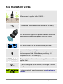
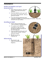
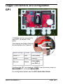
User Manual for the SM200 Soil Moisture Sensor SM200-UM-1.1 Delta-T Devices Ltd Notices Copyright All parts of the SM200 design and documentation are the exclusive right of Delta-T Devices and covered under copyright law, © 2006. Patent(s) pending. CE conformity The SM200 product is CE compliant, conforming to EN61326:1997. Design changes Delta-T Devices Ltd reserves the right to change the designs and specifications of its products at any time without prior notice. User Manual Version: SM200-UM-1.1 May 2006 Delta-T Devices Ltd 128 Low Road, Burwell Cambridge CB5 0EJ UK Tel: +44 1638 742922 Fax: +44 1638 743155 email: [email protected] web: www.delta-t.co.uk Contents Introduction Description Parts list Care and Safety How the SM200 works Operation Cable attachment Installation Logger connections and configuration GP1 DL6 DL2e Other data loggers HH2 moisture meter Calibration Soil calibration Sensor calibration Soil moisture reading 4 4 5 6 7 8 8 9 10 10 11 12 13 14 15 16 18 19 Troubleshooting 20 Technical Reference 21 Specifications Definitions References 21 25 27 Technical Support 28 Soil-specific Calibration 30 Laboratory calibration for non-clay soils Laboratory calibration for clay soils Index SM200 User Manual 1.1 31 33 36 Operation z 3 Introduction Description The SM200 measures soil moisture content at a single location, sampling ~0.5 litres of soil (or other growing medium). It consists of a sealed plastic body, ~40mm diameter, attached to two sensing rods. The probe is fitted with a waterproof connector that is easily connected to extension cables. When taking a reading, the probe rods are inserted directly into the soil. The output from an SM200 is a simple analogue dc voltage. This output can be converted into soil moisture using the supplied general soil calibrations or the probe can be calibrated for specific soils. Features ± 3% scientific accuracy IP68 connector Low salinity sensitivity Excellent temperature stability Minimal soil disturbance Easy installation at depth in augered holes Rugged, weatherproof and buriable SM200 User Manual 1.1 Index z 4 Parts list You consignment may have the following parts: Part Sales Code Description SM200 SM200 soil moisture sensor fitted with M8 connector, in protective packing tube. (supplied with SM200) SM2C/dHH2 1.1m cable for connecting SM200 to HH2 using 25-way D-connector SM2C/w-05 5m cable connects SM200 to data loggers. Terminates in bare wires. EXT/M8-05 EXT/M8-25 5, 10 and 25m extension cables. Terminates in IP68 inline connector. SM-INRD1 1m insertion rod ML2-AG1SL 45mm spiral auger 1.2m long EXT/M8-10 SM200 User Manual 1.1 Quick Start Guide Introduction z 5 Care and Safety The rods of the SM200 are sharp in order to ease insertion. Care must be taken and handling precautions followed. Avoid touching the rods or exposing them to other sources of static damage. Keep the SM200 in its protective tube when not in use. To prevent personal injury and damage to the probe always store and transport the SM200 in this protective tube CAUTION SHARP PINS Handle with care Take care when attaching cables to ensure that the connectors are clean, undamaged and properly aligned before pushing the parts together. Screw together firmly to ensure the connection is water-tight. If the connector is damaged, apply a light smearing of silicon grease to maintain sealing. Do not pull the SM200 out of the soil by its cable. If you feel strong resistance when inserting the SM200 into soil, it is likely you have encountered a stone. Stop pushing and re-insert at a new location. SM200 User Manual 1.1 Index z 6 How the SM200 works When power is applied to the SM200... ...it creates a 100MHz waveform (similar to FM radio). The waveform is applied to a pair of stainless steel rods which transmit an electromagnetic field into the soil. The water content of the soil surrounding the rods... ε ...dominates its permittivity. (A measure of a material’s response to polarisation in an electromagnetic field. Water has a permittivity ≈ 81, compared to soil ≈ 4 and air ≈ 1) The permittivity of the soil has a strong influence on the applied field… Vout …which is detected by the SM200, resulting in a stable voltage output that… Soil Moisture 22 % ...acts as a simple, sensitive measure of soil moisture content. SM200 User Manual 1.1 Operation z 7 Operation Cable attachment Power V+ Signal Ground Extension cables HH2 cable 1.1m 5m 10m 25m Logger cable 5m If you plan to install the SM200 at depth using the insertion rod, pass the connector through the rod before attaching the cable. Take care when attaching cables to ensure that the connectors are clean, undamaged and properly aligned before pushing the parts together. Screw together firmly to ensure the connection is water-tight. Extension cables can be joined up to a recommended maximum of 55m. Cable functions The SM200 is a single-ended sensor. The cables are assigned as follows: Function Name Colour Power to sensor Power V+ Red Sensor output + Signal White Ground Shield (silver) Power VSensor output – SM200 User Manual 1.1 Operation z 8 Installation Surface installation and spot measurements Clear away any stones. Pre-form holes in very hard soils before insertion. Push the SM200 into the soil until the rods are fully inserted. Ensure good soil contact. If you feel strong resistance when inserting the SM200, you have probably hit a stone. Stop, and re-insert at a new location. Installing at depth Auger a 45mm diameter hole. ~10° to vertical is recommended. Fit insertion rod to SM200 - remember to pass the cable through the insertion rod and fit the connector first. Push the SM200 into the soil until rods are fully inserted. Ensure good soil contact. Backfill around the insertion rod. Alternatively Dig a trench, and install horizontally (see diagram). SM200 User Manual 1.1 Operation z 9 Logger connections and configuration GP1 2 SM200s can be connected to each GP1, as shown in the photo. The diagram and table illustrate the connections for Channel 1: SM200 wiring Colour GP1 terminal Power V+ Red CH1 (PWR) Signal White CH1 (+) Ground Shield CH1 (GND) and CH1 (-) Configure the GP1 by choosing “SM200” from the sensor menu in DeltaLINK-PC or Pocket DeltaLINK. For configuration details see the GP1 Quick Start Guide. SM200 User Manual 1.1 Index z 10 DL6 Up to 6 SM200s can be connected to each DL6. These details illustrate connection to Channel1: SM200 wiring Colour DL6 terminal Power V+ Red V+ Signal White IN+ Ground Shield INand 0V Configure the DL6 by choosing “SM200” from the sensor menu in DeltaLINK-PC or Pocket DeltaLINK. For configuration details refer to the DL6 Quick Start Guide. SM200 User Manual 1.1 Operation z 11 DL2e Configure the DL2e by choosing one of the SM200 sensor codes from the LS2Win sensor library, according to your soil type. Up to 60 SM200s can be connected to each DL2e. These details illustrate connection to Channel 58 using the LAC1 input card configured in 15-channel mode, and warm-up channel 63: SM200 wiring Colour DL2e terminal Power V+ Red 63 NO Signal White 58+ Ground Shield 58and 61- For configuration details see the DL2e User Documentation. SM200 User Manual 1.1 Index z 12 Other data loggers The SM200 should be connected as a single-ended, powered sensor. Configure the logger input as a voltage sensor, approximately 0 to 1.0 volts corresponding to ~0 to 60% water content – see next section. The SM200 has been optimised for a 1 second warm-up period. It is recommended that the sensor is not powered continuously. Configure the logger to convert the SM200 readings into soil moisture using the polynomial or linearisation tables – see Calibration. SM200 User Manual 1.1 Operation z 13 HH2 moisture meter Connect the SM200 to the HH2 meter. Press Esc to turn the meter on, and if necessary press again until the HH2 displays the start-up screen. Set the meter to read from an SM200: ► Press Set and scroll down to the Device option. ► Press Set again and scroll down to select SM200: Device: v SM200 ► Press Set to confirm this choice. If you intend to store readings, it may be helpful to define each reading by setting a plot label and sample number – accessed by pressing Set and scrolling to the Data option. Press Read to take a reading (it takes about 2 seconds). You can choose different units from the Display option. SM200 Store? 20.3%vol Press Store to save or Esc to discard the reading. Remove the SM200 and move to a new location... If you have saved data, connect your HH2 to a PC and run HH2Read to retrieve the readings. Refer to the HH2 User Manual for further details. SM200 User Manual 1.1 Index z 14 Calibration The SM200 is provided with general calibrations for mineral and organic soils which can be used to convert the output from the sensor directly into soil moisture when used with Delta-T loggers and the HH2 moisture meter. This section explains how these calibrations work, how to adapt them for other soils and how to provide calibrations for other data loggers. The SM200 measures volumetric soil moisture, θ, by detecting the dielectric properties of the damp soil – the permittivity, ε, or more conveniently the refractive index, which is closely equivalent to √ε. The SM200 response is best understood in these stages: 1. Soil calibration θ → √ε 2. Sensor calibration V → √ε Soil calibrations √ε SM200 dielectric performance 8.0 8.0 6.0 6.0 4.0 √ε 4.0 2.0 2.0 0.0 0.0 0.0 0.2 0.4 0.6 θ 0 0.8 0.2 0.4 0.6 0.8 1 1.2 V 3. Soil moisture reading V→θ SM200 soil moisture reading 80% Organic 60% θ Mineral 40% 20% 0% 0 0.2 0.4 0.6 0.8 1 1.2 V SM200 User Manual 1.1 Soil-specific Calibration z 15 Soil calibration Damp soil is essentially a mixture of soil particles, air and water, and together these components determine its dielectric properties, including the refractive index √ε. The refractive index of the mixture is approximated simply by adding the contributions from the individual components [ref 4.]. For a particular soil, the contribution from the soil particles can be assumed to be constant, so the refractive index measured by the SM200 is only affected by changes to the water content, θ. This relationship simplifies to: ε = a0 + a1 ⋅ θ where the coefficients a0 and a1 conveniently parameterise the dielectric properties of soils. Soil calibrations Soil refractive index (√ε) 8.0 6.0 4.0 Slope (a1) 2.0 Offset (a0) 0.0 0.0 0.2 0.4 0.6 3 0.8 -3 Soil moisture (m .m ) Note that: a0 = ε dry _ soil is usually between 1.3 to 2.3 a1 corresponds approximately to ε water − 1 and usually takes a value about 8.0. Real soil values for a0 and a1 can vary significantly from these guidelines when they are affected by other factors – in particular, bound water in clay soils may result in higher values of a1. SM200 User Manual 1.1 Index z 16 General soil calibrations Most soils can be characterised simply by choosing one of the two general calibrations we supply, one for mineral soils (predominantly sand, silt and clay) and one for organic soils (with a high organic matter content). a0 a1 Mineral soils 1.6 8.4 Organic soils 1.3 7.7 General soil calibrations Soil refractive index (√ε) 8.0 Mineral 6.0 Organic 4.0 2.0 0.0 0.0 0.2 0.4 0.6 3 0.8 -3 Soil Moisture (m .m ) These values have been used to generate the polynomial conversions and linearisation tables in the Soil moisture reading section. Soil-specific calibration Instead of adopting these general calibrations, you may wish to determine specific calibration values of a0 and a1 for your soil. This procedure is fairly straightforward if you can get access to standard laboratory equipment and is described in detail in Appendix A. Soil specific calibration can significantly improve the accuracy of individual readings - but make less of an improvement to readings where installation and sampling errors are high. SM200 User Manual 1.1 Soil-specific Calibration z 17 Sensor calibration Each SM200 is individually adjusted to provide consistent dielectric performance: SM200 dielectric performance Soil refractive index (√ε) 8.0 6.0 4.0 2.0 0.0 0 0.2 0.4 0.6 0.8 1 1.2 SM200 output (Volts) This response can be approximated either by a polynomial or by a linearisation table: Polynomial (use for SM200 readings from 0 to 1.1 Volts) ε = 1.0 + 16.103V − 38.725V 2 + 60.881V 3 − 46.032V 4 + 13.536V 5 where V is the SM200 output in Volts Linearisation table (use for SM200 readings from 0 to 1.2 Volts) √ε V √ε V √ε V √ε 0.000 1.011 0.150 2.729 0.400 4.102 1.100 7.290 0.030 1.453 0.180 2.956 0.600 4.956 1.150 7.610 0.060 1.842 0.220 3.218 0.820 5.939 1.200 7.982 0.090 2.179 0.260 3.446 0.960 6.571 1.220 8.205 0.120 2.473 0.310 3.701 1.040 6.960 1.800 9.000 V SM200 User Manual 1.1 Index z 18 Soil moisture reading Polynomial conversion Combining the Soil calibrations and Sensor calibration steps, the conversion equation becomes: θ= [1.0 + 16.103V − 38.725V 2 ] + 60.881V 3 − 46.032V 4 + 13.536V 5 − a 0 a1 where a0 and a1 are the calibration coefficients. For a generalised mineral soil this becomes: θ mineral = − 0 .071 + 1 .917 V − 4 .61V 2 + 7 .248V 3 − 5 .48V 4 + 1 .611V 5 And for a generalised organic soil: θ organic = −0.039 + 2.091V − 5.029V 2 + 7.907V 3 − 5.978V 4 + 1.758V 5 Linearisation table conversion Alternatively, the conversion from SM200 reading (Volts) to soil moisture θ (m3.m-3 or %vol) can be accomplished by a linearisation table. The following table lists the values used for the DL2e data logger: Soil moisture %vol -4 0 4 8 12 16 20 24 28 32 36 40 44 48 SM200 User Manual 1.1 Mineral soil Volts Organic soil Volts -2.090 0.041 0.068 0.099 0.135 0.178 0.230 0.292 0.365 0.443 0.523 0.601 0.676 0.751 -2.090 0.019 0.041 0.066 0.094 0.126 0.164 0.209 0.262 0.324 0.393 0.466 0.538 0.609 Soil moisture %vol 52 56 60 64 68 72 76 80 84 88 92 96 100 104 Mineral soil Volts Organic soil Volts 0.826 0.901 0.975 1.043 1.103 1.156 1.199 1.237 1.269 1.297 1.322 1.347 1.800 2.090 0.678 0.747 0.816 0.884 0.952 1.017 1.076 1.127 1.171 1.210 1.244 1.278 1.800 2.090 Soil-specific Calibration z 19 Troubleshooting Always try to identify which part of the measurement system is the source of the difficulty. For the SM200 this may fall into one of the following areas: The measurement device What equipment is being used to read the probe output? • A Delta-T HH2 Moisture Meter • A Delta-T data logger such as the GP1, DL6 or DL2e Consult the user manuals or the on-line help for these devices and their related software. Try alternative types of equipment if you have them available. Check that you are using an appropriate soil calibration and the correct conversion method – see Calibration section. The SM200 itself Try to isolate the problem into one of the following areas • The SM200 or the connecting cable Then try to narrow down the area further • Mechanical problems faults, or damage • Electrical or electronic problems or faults Functional check The following two simple checks can be used to establish whether your SM200 is functioning within expected bounds: Air reading Hold the SM200 away from other objects and take a reading using an HH2 meter, or other meter or logger. The reading should be 0 ±12mV when used with a 5m cable. Finger reading Hold the SM200 with your fingers wrapped closely (but carefully!) around the two metal rods and take a reading using an HH2 meter or other meter or logger. The reading should be between 500 to 750mV. SM200 User Manual 1.1 Index z 20 Technical Reference Specifications Range and Notes Accuracy* ± 3 %vol 0 to 50 %vol Salinity errors ± 3.5 %vol 0 to 40 %vol, over Power requirement 5 to 14V 15mA typical 1 second warm-up recommended 200ms minimum Output signal 0 to 1.0V Nominal 0 to 60 %vol Environmental sealing IP68 Sensor buriable, sealed to IP68 Operating range -20 to +60°C Readings in frozen soil are not meaningful -1 50 to 500 mS.m -1 (0.5 to 5 dS.m ) * Accuracy figures apply to calibration soils and over 0 to 60°C. Percentages quoted as %vol are % volumetric water content. Conductivity response SM200 User Manual 1.1 Soil-specific Calibration z 21 Temperature response The SM200 temperature response in any particular soil will depend on a combination of effects: The SM200 electronics has a very low temperature sensitivity, and makes a negligible contribution to the overall sensitivity. The refractive index of water (√ε, see Calibration section) reduces as the temperature increases. This produces a negative temperature response particularly in soils or substrates with high water content. Water that is bound to the surface of soil particles has a much lower refractive index than free water. The percentage of bound water decreases with temperature and this produces a positive temperature response particularly in clay soils at lower water contents. The last two effects partially offset each other, but in soil conditions where one or the other effect dominates, the SM200 will appear to have a significant temperature response. This illustration is based on the model in reference 7: Illustrating temperature dependence of SM200 readings in clay soil 0.5 Soil moisture content (m3.m-3) θ ∼ 0.4 θ ∼ 0.3 0.4 θ ∼ 0.2 θ ∼ 0.1 bound water 0.3 0.2 0.1 0 0 10 20 30 40 50 Soil temperature (°C) Note: ice has a quite different refractive index from water, so SM200 readings cannot be interpreted reliably when inserted into soil below 0°C. SM200 User Manual 1.1 Index z 22 Sampling Volume The SM200 is most sensitive to signals very close to the two rods, but a small proportion of the signal reaches up to 50mm from the rods. For best accuracy we recommend taking readings in at least 0.5 litres of soil, preferably 1.0 litre. SM200s may interact if they are placed too close together – they should be separated by at least 100mm. The sensitivity field for an SM200 inserted in water has been tested as shown in this figure (the vertical scale is in arbitrary units): SM200 User Manual 1.1 Soil-specific Calibration z 23 Electromagnetic Compatibility (EMC) General information SM200 is a Class A product, intended for operation in nonresidential environments. Only use cables and accessories authorised by Delta-T (sensor cables from other sources for example can adversely affect product performance and affect quality of results). If possible route cables along the soil surface or bury them – this also reduces possible trip hazard and animal damage. Do not modify the product or its supplied accessories. Regulatory information Europe SM200 has been assessed for CE compliance under the European Union EMC directive 89/336/EEC and conforms to the appropriate standards, EN61326 (1997), providing the product is used as described in this manual. Use of non Delta-T cables and accessories may invalidate this. FCC compliance (USA) This device complies with part 15 of the FCC Rules. Operation is subject to the following conditions: 1. This device may not cause harmful interference 2. This device must accept any interference received, including interference that may cause undesired operation Note: This equipment has been tested and found to comply with the limits for a Class A digital device, pursuant to part 15 of the FCC rules. These limits are designed to provide reasonable protection against harmful interference when the equipment is operated in a commercial environment. This equipment generates, uses, and can radiate radio frequency energy and, if not installed and used in accordance with the instruction manual, may cause harmful interference to radio communications. Operation of this equipment in a residential area is likely to cause harmful interference in which case the user will be required to correct the interference at his/her own expense. Modifications not expressly approved by the manufacturer could void the user’s authority to operate the equipment under FCC rules SM200 User Manual 1.1 Index z 24 Definitions Volumetric Soil Moisture Content is defined as θV = VW VS where Vw is the volume of water contained in the sample and Vs is the total volume of the soil sample. The preferred units for this ratio are m3.m-3, though %vol is frequently used. Soil Moisture Content varies from approx. 0.02 m3.m-3 for sandy soils at the permanent wilting point, through approx. 0.4 m3.m-3 for clay soils at their field capacity, up to values as high as 0.85 m3.m-3 in saturated peat soils. Gravimetric Soil Moisture Content is defined as θG = MW MS -1 g.g where MW is the mass of water in the sample, and M S is the total mass of the dry sample. To convert from volumetric to gravimetric water content, use the equation ρ θ G = θV × W ρS where ρW is the density of water (= 1g.cm-3), and ρ S is the bulk density of the sample ( MS ). VS Organic and Mineral soil definitions: The general calibrations have been optimised to cover a wide range of soil types, based on the following definitions: optimised around Soil type organic content: use for organic contents: bulk density range: -3 (g.cm ) use for bulk densities: -3 (g.cm ) Mineral ~ 1 %C < 7 %C 1.25 - 1.5 > 1.0 Organic ~ 40 %C > 7 %C 0.2 - 0.7 < 1.0 SM200 User Manual 1.1 Soil-specific Calibration z 25 Salinity The preferred SI units for ionic conductivity are mS.m-1 (where S is Siemens, the unit of electric conductance = ohm-1). The following conversions apply: 1 mS.m -1 = 0.01 dS.m-1 -1 = 0.01 mS.cm -1 = 10 µS.cm Soil salinity is also partitioned into the following descriptive categories: non-saline -1 0 - 200 mS.m slightly saline 200 - 400 mS.m moderately saline 400 - 800 mS.m strongly saline 800 - 1600 mS.m extremely saline > 1600 mS.m SM200 User Manual 1.1 -1 -1 -1 -1 Index z 26 References 1. Gaskin, G.J. and J.D. Miller, 1996 Measurement of soil water content using a simplified impedance measuring technique. J. Agr. Engng Res 63, 153-160 2. Topp, G.C., J. L. Davis and A. P Annan 1980 Electromagnetic determination of soil water content. Water Resour. Res 16(3) 574-582 3. Whalley, W.R. 1993 Considerations on the use of time-domain reflectometry (TDR) for measuring soil moisture content. Journal of Soil Sci. 44, 1-9 4. White, I., J.H. Knight, S.J. Zegelin, and Topp, G.C. 1994 Comments on ‘Considerations on the use of time-domain reflectometry (TDR) for measuring soil water content’ by W R Whalley Journal of Soil Sci. 45, 503-508 5. Roth, C.H., M.A. Malicki, and R. Plagge, 1992 Empirical evaluation of the relationship between soil dielectric constant and volumetric water content as the basis for calibrating soil moisture measurements. Journal of Soil Sci. 43, 1-13 6. Knight, J.H. 1992 Sensitivity of Time Domain Reflectometry measurements to lateral variations in soil water content. Water Resour. Res., 28, 2345-2352 7. Or, D. and J.M. Wraith 1999 Temperature effects on soil bulk dielectric permittivity measured by time domain reflectrometry: A physical model. Water Resour Res., 35, 371-383 SM200 User Manual 1.1 Soil-specific Calibration z 27 Technical Support Terms and Conditions of Sale Our Conditions of Sale (ref: COND: 1/00) set out Delta-T's legal obligations on these matters. The following paragraphs summarise Delta-T's position but reference should always be made to the exact terms of our Conditions of Sale, which will prevail over the following explanation. Delta-T warrants that the goods will be free from defects arising out of the materials used or poor workmanship for a period of twelve months from the date of delivery. Delta-T shall be under no liability in respect of any defect arising from fair wear and tear and the warranty does not cover damage through misuse or inexpert servicing, or other circumstances beyond our control. If the buyer experiences problems with the goods they shall notify Delta-T (or Delta-T’s local distributor) as soon as they become aware of such problem. Delta-T may rectify the problem by supplying replacement parts free of charge, or by repairing the goods free of charge at Delta-T's premises in the UK, during the warranty period. If Delta-T requires that goods under warranty be returned to them from overseas for repair, Delta-T shall not be liable for the cost of carriage or for customs clearance in respect of such goods. However, we much prefer to have such returns discussed with us in advance and we may, at our discretion, waive these charges. Delta-T shall not be liable to supply products free of charge or repair any goods where the products or goods in question have been discontinued or have become obsolete, although Delta-T will endeavour to remedy the buyer’s problem. Delta-T shall not be liable to the buyer for any consequential loss, damage or compensation whatsoever (whether caused by the negligence of the Delta-T, our employees or distributors or otherwise) which arise from the supply of the goods and/or services, or their use or resale by the buyer. Delta-T shall not be liable to the buyer by reason of any delay or failure to perform our obligations in relation to the goods and/or services, if the delay or failure was due to any cause beyond the Delta-T’s reasonable control. SM200 User Manual 1.1 Index z 28 Service and Spares Users in countries that have a Delta-T Distributor or Technical Representative should contact them in the first instance. Spare parts for our own instruments can be supplied from our works. These can normally be despatched within a few working days of receiving an order. Spare parts and accessories for sensors or other products not manufactured by Delta-T may have to be obtained from our supplier and a certain amount of additional delay is inevitable. No goods or equipment should be returned to Delta-T without first obtaining the agreement of Delta-T or our distributor. On receipt at Delta-T, the goods will be inspected and the user informed of the likely cost and delay. We normally expect to complete repairs within a few working days of receiving the equipment. However, if the equipment has to be forwarded to our original supplier for specialist repairs or recalibration, additional delays of a few weeks may be expected. Technical Support Technical Support is available on Delta-T products and systems. Users in countries that have a Delta-T Distributor or Technical Representative should contact them in the first instance. Technical Support questions received by Delta-T will be handled by our Tech Support team. Your initial enquiry will be acknowledged immediately with a “T number” and an estimate of time for a detailed reply. Make sure to quote our T number subsequently so that we can easily trace any earlier correspondence. In your enquiry, always quote instrument serial numbers, software version numbers, and the approximate date and source of purchase where these are relevant. Contact details: Tech Support Team Delta-T Devices Ltd 128 Low Road, Burwell, Cambridge CB5 0EJ, U.K. email: [email protected] Web site: www.delta-t.co.uk Tel: +44 (0) 1638 742922 Fax: +44 (0) 1638 743155 SM200 User Manual 1.1 Soil-specific Calibration z 29 Soil-specific Calibration This note provides details of 2 techniques for generating soil-specific calibrations: 1. Laboratory calibration for substrates* and non-clay soils 2. Laboratory calibration for clay soils * We use the term substrate to refer to any artificial growing medium. Underlying principle Soil moisture content (θ) is proportional to the refractive index of the soil (√ε) as measured by the SM200 (see Calibration section). The goal of calibration is to generate two coefficients (a0, a1) which can be used in a linear equation to convert probe readings into soil moisture: ε = a 0 + a1 × θ SM200 User Manual 1.1 Index z 30 Laboratory calibration for non-clay soils This is the easiest technique, but it’s not suitable for soils that shrink or become very hard when dry. Equipment you will need: SM200 and meter Soil corer (if doing a calibration for a cohesive soil rather than sand or a substrate) Heat-resistant beaker (≥ 0.5 litre) Weighing balance (accurate to < 1g) Temperature controlled oven (for mineral soils or substrates) Process Notes and example Collect a damp sample of the soil or substrate. This sample needs to be unchanged from its in-situ density, to be ≥ 0.5 litre, to have the correct dimensions to fit the beaker, and to be generally uniform in water content. For cohesive soils this is most easily done with a soil-corer. Sandy soils can be poured into the beaker, but you should take the subsequent measurements immediately, as the water will quickly begin to drain to the bottom of the beaker. Compressible soils and composts often require measurement of the in-situ density and then need to be carefully reconstituted at that density within the beaker. Measure the volume occupied by the sample. Ls = 463.5ml Weigh the sample, including the beaker. Ww = 743.3g SM200 User Manual 1.1 Soil-specific Calibration z 31 Insert SM200 into the sample and record its output in Volts. Vw = 0.350V Dry the sample thoroughly. With mineral soils this is usually achieved by keeping it in the oven at 105°C for several hours or days (the time required depends on the sample size and porosity). For organic soils and composts it’s usual to air-dry the sample to avoid burning off any volatile factions. Weigh the dry sample in the beaker. W0 = 627.2g Re-insert the SM200 into the dry sample and record this reading. V0 = 0.051V Calculate a0 For the SM200, ε = 1.0 + 16.103V − 38.725V 2 + 60.881V 3 − 46.032V 4 + 13.536V 5 In the dry soil V = V0 = 0.051 Volts, and substituting this value into the above equation gives ε 0 = 1.73 Since θ 0 = 0, this is the value needed for a0 a0 = 1.73 Calculate θw The water content of the wet soil, θw, can be calculated from the weight of water lost during drying, (Ww – W0) and its volume, Ls: θ w = (Ww − W0 ) Ls = (743.3 − 627.2) 463.5 = 0.25 SM200 User Manual 1.1 Index z 32 θw = 0.25 Calculate a1 In the wet soil V = Vw = 0.350 Volts and substituting gives ε w = 3.88 Finally a1 = (ε w − ε0 ) (θ w − θ 0 ) = (3.88 − 1.73) (0.25 − 0) = 8.60 a1 = 8.60 Laboratory calibration for clay soils This technique is adapted to avoid the near-impossibility of inserting the SM200 into completely dry clay soil. It requires taking measurements at 2 significantly different, but still damp, moisture levels. Equipment you will need: SM200 and meter Soil corer Heat-resistant beaker (≥ 500ml) Weighing balance (accurate to < 1g) Temperature controlled oven Process Notes and example Collect a wet sample of the clay soil: 25 to 30% water content would be ideal. This sample needs to be unchanged from its in-situ density, to be ≥ 500ml, to have the correct dimensions to fit the beaker, and to be generally uniform in water content. This is most easily done with soil-corer. Measure the volume occupied by the sample. Ls = 463.5ml Weigh the wet sample, including the beaker. Ww = 743.3g SM200 User Manual 1.1 Soil-specific Calibration z 33 Insert SM200 into the wet sample and record its output in Volts. Vw = 0.349V Dry the sample until still moist, ~15% water content. Gentle warming can be used to accelerate the process, but take care not to over-dry in places, and allow time for the water content to equilibrate throughout the sample before taking a reading. Reweigh. Wm = 693.2g Re-measure with the SM200. Vm = 0.180V Dry the sample thoroughly. With mineral soils this is usually achieved by keeping it in the oven at 105°C for several hours or days (the time required depends on the sample size and porosity). Weigh the dry sample in the beaker. W0 = 627.2g SM200 User Manual 1.1 Index z 34 Calculations Substituting in the SM200 equation ε = 1.0 + 16.103V − 38.725V 2 + 60.881V 3 − 46.032V 4 + 13.536V 5 provides two dielectric values, √εw and √εm, at two known water contents, θw and θm For the wet soil Substituting Vw = 0.349 gives ε w = 3.88 = a0 + a1 ⋅ θ w for θ w = (743.3 − 627.2) 463.5 = 0.25 For the moist soil Substituting Vm = 0.180 gives ε m = 2.95 = a0 + a1 ⋅ θ m For θ m = (693.2 − 627.2) 463.5 = 0.14 Calculate a1 Then a1 = (ε w − εm ) (θ w − θ m ) = 8.56 a1 = 8.56 Calculate a0 and a0 = ε w − (a1 ⋅ θ w ) = 1.73 a0 = 1.73 SM200 User Manual 1.1 Soil-specific Calibration z 35 Index A I Accuracy, 21 Auger, 5, 9 Installation buried, 9 insertion rod, 5, 8, 9 surface, 9 C Calibration check, 20 generalised, 19 sensor, 15, 18, 19 soil, 15, 16, 19 soil-specific, 30 Care and safety, 6 Certification emc, 24 Connections, 10 Conversions linearisation table, 13, 17, 18, 19 polynomial, 13, 17, 18 D Data logger, 13, 19, 20 DL2e, 12, 19, 20 DL6, 11, 20 GP1, 10, 20 other, 13 Definitions, 25 Dielectric performance, 18 refractive index, 15, 16, 30 E M Meter, 20 Moisture content, 4, 7, 27, 30 P Patent, 2 Permittivity, 7, 15, 27 R Range, 21 References, 27 Rods, 4, 6, 7, 9 S Sales code, 5 Salinity, 21, 26 Servicing, 29 Soil clay, 16, 17, 25, 30, 31, 33 mineral, 15, 17, 19, 31, 32, 34 organic, 15, 17, 19, 25, 32 stony, 9 Specifications, 2, 21 Extension cables, 8 T G Technical support, 28, 29 Troubleshooting, 20 GP1, 10, 20 H W Wiring, 10 HH2, 5, 14, 15, 20 SM200 User Manual 1.1 Index z 36