1
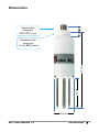
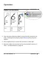
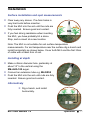
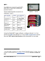
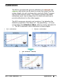
User Manual for the ML3 ThetaProbe Soil Moisture Sensor ML3-UM-1.0 Delta-T Devices Ltd Notices Patents The ML3 ThetaProbe has been jointly developed by The Macaulay Land Use Research Institute and Delta-T Devices Ltd. and uses novel measurements. They are subject to the following patents: UK: GB2300485B US: 5804976 Copyright All parts of the ML3 ThetaProbe design and documentation are the exclusive right of Delta-T Devices and covered under copyright law. © 2013 Delta-T Devices Ltd EMC Compliance See page 29. Design changes Delta-T Devices Ltd reserves the right to change the designs and specifications of its products at any time without prior notice. User Manual Version: ML3-UM-1.0 April 2013 Delta-T Devices Ltd Tel: +44 1638 742922 130 Low Road, Fax: +44 1638 743155 Burwell email: [email protected] Cambridge CB25 0EJ web: www.delta-t.co.uk UK Contents Introduction Description Features Dimensions Parts list Care and Safety How the ML3 works Operation Cable Connections Installation Logger connections and configuration GP2 5 5 5 6 7 8 9 10 10 11 12 12 GP1 13 DL6 14 DL2e 15 Other data loggers 16 HH2 Meter Calibration Soil calibration 17 18 18 Sensor calibration 21 Soil moisture reading 22 Troubleshooting 24 Technical Reference 26 Specifications Volumetric water content ML3 User Manual 1.0 26 26 Introduction 3 Temperature 26 Definitions 30 References 32 Technical Support 33 Appendix 1 35 Soil-specific Calibration Laboratory calibration for non-clay soils Laboratory calibration for clay soils 35 36 39 Appendix 2: 42 The ML3 Temperature Sensor ML3 Temperature Measurement 42 43 Effect of Temperature on Water Permittivity 44 Resistance to Temperature Lookup Table 45 Index ML3 User Manual 1.0 46 Introduction 4 Introduction Description The ML3 measures soil moisture content and temperature 1. Its sealed plastic body is attached to four sensing rods which insert directly into the soil for taking readings. A waterproof plug connects to a choice of signal cables. Both extension cables and extension tubes can be used. The soil moisture output signal is a differential analogue DC voltage. This is converted to soil moisture by a data logger or meter using the supplied general soil calibrations. It can also be calibrated for specific soils. Features Soil moisture accurate to ± 1% Soil temperature to ± 0.5°C over 0-40°C Low salinity sensitivity Excellent stability Minimal soil disturbance Easy installation at depth in augered holes Waterproof connector to IP68 Rugged, weatherproof and can be buried. Good electrical immunity Choice of cabling system options Cable connector, cylindrical profile and extension tube design simplifies removal for servicing. See also Specifications on page 26 1 A data logger is required for temperature measurements ML3 User Manual 1.0 Introduction 5 Dimensions 13 Signal cable connector IP68, M12, 5 pin 12 Extension tube connector ¾ inch BSP thread 157.5 mm 60 mm 39.8 mm ML3 User Manual 1.0 Introduction 6 Parts list Your shipment may include the following: Part Sales Code Description ML3 ML3 sensor with Quick Start Guide SMSC/dHH2 0.9m cable connects to HH2 meter via 25-way D-connector SMSC/sw05 5m cable with 100 mm flying leads for GP2, GP1 or DL6 logger 5m cable with SMSC/lw-05 200mm flying leads for DL2e logger ML3 User Manual 1.0 EXT/5W-05 EXT/5W-10 EXT/5W-25 5, 10 and 25m extension cables. IP68 M12 connectors ML/EX50 ML/EX100 50 and 100cm Extension Tube SM-AUG100 45mm spiral auger 1.2m long Introduction 7 ML3 sensor, HH2 meter, cable SMSC/d-HH2, Insertion kit ML-INK1, 4 spare steel pins, spare battery, carry case HHCC3, HH2 manual, ML3 Quick Start ML3-Kit Care and Safety The rods of the ML3 are sharp in To prevent personal injury and damage to the probe always store and transport the ML3 in this protective tube order to ease insertion. Care must be taken and handling precautions followed. CAUTION SHARP PINS Take care when attaching cables to ensure that the connectors are clean, undamaged and properly aligned before pushing the parts together. Do not pull the ML3 out of the soil by its cable. If you feel strong resistance when inserting the ML3 into soil, it is likely you have encountered a stone. Stop pushing and re-insert at a new location. Avoid touching the rods or exposing them to other sources of static damage, particularly when powered up. þ Keep the ML3 in its protective tube when not in use. ML3 User Manual 1.0 Introduction 8 How the ML3 works When power is applied to the ML3... ...it creates a 100MHz waveform (similar to FM radio). The waveform is applied to an array of stainless steel rods which transmit an electromagnetic field into the soil. The water content of the soil surrounding the rods... ε ...dominates its permittivity. (A measure of a material’s response to polarisation in an electromagnetic field. Water has a permittivity ≈ 81, compared to soil ≈ 4 and air ≈ 1) The permittivity of the soil has a strong influence on the applied field… Vout Soil Moisture 22 % …which is detected by the ML3, resulting in a stable voltage output that… ...acts as a simple, sensitive measure of soil moisture content. ML3 User Manual 1.0 Introduction 9 Operation Cable Connections brown white blue black grey green HH2 cable 0.9m Extension cables 5m 10m 25m Power 0V Power V+ Soil Moisture Signal HI Soil Moisture Signal LO Temperature + Cable shield Logger cables 5m with 100 or 200 mm bare leads Take care when attaching cables to ensure that the connectors are clean, undamaged and properly aligned before pushing the parts together. Screw together firmly to ensure the connection is water-tight. Extension cables can be joined up to a recommended maximum of 100m – see Specifications on page 26 ML3 User Manual 1.0 Operation 10 Installation Surface installation and spot measurements Clear away any stones. Pre-form holes in very hard soils before insertion. Push the ML3 into the soil until the rods are fully inserted. Ensure good soil contact. If you feel strong resistance when inserting the ML3, you have probably hit a stone. Stop, and re-insert at a new location. Note: The ML3 is not suitable for soil surface temperature measurements. For soil temperature near the surface dig a trench and install horizontally as shown below. Cover both ML3 and the first 30cm of cable with at least 5cm of soil. Installing at depth Make a 45mm diameter hole, preferably at about 10° to the vertical using the SM-AUG-100 auger. Connect an extension tube e.g. ML/EX50 Push the ML3 into the soil until rods are fully inserted. Ensure good soil contact. Alternatively Dig a trench, and install horizontally. ML3 User Manual 1.0 Operation 11 Logger connections and configuration GP2 6 ML3s can connect to each GP2 wired as a differential, powered sensors. 12 ML3s can be connected if you do not use the temperature sensor. For this you will also need a 5 gland expansion lid GP2-G5-LID. These details illustrate connection to Channels 1 and 2: ML3 wiring Colour GP2 terminal Power 0V and Thermistor LO brown CH1 (PGND) Power V+ white CH1 (PWR) Soil Moisture Signal HI blue CH1 (+) Soil Moisture Signal LO black CH1 (-) Thermistor HI grey CH2(+) and CH2(-) Cable shield green CH1 (PGND) For configuration details see the DeltaLINK 3 2 software ML3 sensor Info Panel, Help or the GP2 User Manual. Download the latest version of the DeltaLINK logger software from www.delta-t.co.uk or from our Software and Manuals DVD 2 The GP2 logger needs the PC logger software DeltaLINK 3. This can be obtained from www.delta-t.co.uk or the Software and Manuals DVD. ML3 User Manual 1.0 Operation 12 GP1 Two ML3s can connect to each GP1. Each ML3 is wired as a differential, powered sensor. These details illustrate connection to Channels 1 and 3: ML3 wiring Colour GP1 terminal Power 0V and Thermistor LO brown CH1 (GND) or Temp (GND) Power V+ white CH1 (PWR) Soil Moisture Signal HI blue CH1 (+) Soil Moisture Signal LO black CH1 (-) Temperature + grey Temp3 (IN) Cable shield green CH1 (GND) Using the DeltaLINK 3 logger software, configure channel 1 or 2 as sensor type ML3 and channel 3 or 4 as an ML3 Temperature sensor. See also GP1 Quick Start Guide and the DeltaLINK on-line Help. 3 The GP1 logger needs the PC logger software DeltaLINK version 3 or later. A free upgrade can be obtained from www.delta-t.co.uk or from the Software and Manuals DVD. ML3 User Manual 1.0 Operation 13 DL6 6 ML3s can be connected to a DL6. Each ML3 is wired as a differential, powered sensor. A DL6 logger can only read one ML3 temperature sensor. These details illustrate connection to channels 6 & 7: ML3 wiring Colour DL6 terminal Power 0V brown 0V Power V+ white V+ Soil Moisture Signal HI blue IN+ Soil Moisture Signal LO black IN- Temperature + grey RES IN+ Cable shield green In DeltaLINK 4 configure channel 6 as type ML3 and channel 7 as a type ML3 Temperature sensor. See also the DL6 Quick Start Guide and the DeltaLINK online Help. 4 The DL6 logger needs the PC logger software DeltaLINK version 3 or later. A free upgrade can be obtained from www.delta-t.co.uk or from the Software and Manuals DVD. ML3 User Manual 1.0 Operation 14 DL2e Up to 60 ML3s can be connected to a DL2e logger (if not using the temperature sensor channel). Up to 30 ML3s can be connected if also reading the temperature sensor. Each ML3 is connected as a differential, powered sensor. These details illustrate connection to Channels 57 and 58 using a LAC1 input card configured in 15-channel mode, and warm-up channel 63: ML3 wiring Colour DL2e terminal Power 0V brown CH62- or 61- Power V+ white CH63 NO Soil Moisture Signal HI blue CH58+ Soil Moisture Signal LO black CH58- Temperature + grey CH57+ and CH57- Cable shield green CH61- or 62- Configure the chosen DL2e logger channels by selecting the appropriate S3M and S3O sensor types for mineral and organic soils and S3T for the temperature sensor type listed in the Ls2Win 5 sensor library. See the DL2e User Manual and the Ls2Win online help 5 You need a PC running Ls2Win version 1.0 SR10 or later. A free upgrade can be obtained from www.delta-t.co.uk or from the Software and Manuals DVD. ML3 User Manual 1.0 Operation 15 Other data loggers The ML3 should be connected as a differential, powered sensor. Configure the logger to convert the ML3 readings from milliVolts into soil moisture units by using either :Polynomial conversion on page 22 or Linearisation table conversion on page 23 Output signals in the range 0 to 1.0 volts from the ML3 correspond to a range of ~0 to 60% water content in mineral soils – see Linearisation table conversion on page 23. Note: The ML3 has been optimised for warm-up of 0.5 to 1 second duration. It is recommended that the sensor is not powered continuously. The temperature sensor output should be read as a resistance and the logger configured with a look-up table to covert the measured resistance to temperature. See ML3 Temperature Measurement on page 43 and Resistance to Temperature Lookup Table on page 45. ML3 User Manual 1.0 Operation 16 HH2 Meter You need version 2.7 or later for both the PC software HH2Read and the HH2 firmware (see foot of page). Connect the ML3 to the HH2 meter. Press Esc to turn the meter on, and if necessary press again until the HH2 displays the start-up screen. Set the meter to read from an ML3: ► ► Press Set and scroll down to the Device option. ► Press Set to confirm this choice. Press Set again and scroll down to select ML3. Device: ML3 Make sure the HH2 is correctly configured for your soil type: ► ► At the start-up screen, press Set and scroll down to the Soil Type option. ► Press Set to confirm this choice. Press Set again and scroll down to the appropriate soil type (use Mineral for sand, silt or clay soils or Organic for peaty soils) Soil Type: Mineral Choose the units you want for displaying readings. ► ► ► At the start-up screen, press Set and scroll down to the Display option. Press Set again and scroll down to select units. Press Set to confirm this choice. Press Read to take a reading. Press Store to save or Esc to discard the reading. Remove the ML3 from the soil and move to a new location... If you have saved data, connect your HH2 to a PC and run HH2Read to retrieve the readings. ML3 Store? 20.3 %vol See also: Support for the ML3 Soil Moisture Sensor with an HH2 and HH2 User Manual and HH2 User Manual Addendum to V4 - ML3. Note: the HH2 does not display or store ML3 temperature readings. Note: For an upgrade contact Delta-T. ML3 User Manual 1.0 Operation 17 Calibration The ML3 is provided with general calibrations for mineral and organic soils which can be used to convert the output from the sensor directly into soil moisture when used with Delta-T loggers and the HH2 moisture meter. This section explains how these calibrations work, how to adapt them for other soils and how to provide calibrations for other data loggers. The ML3 measures volumetric soil moisture θ, by detecting the dielectric properties of the damp soil – the permittivity, ε, or more conveniently the refractive index, which is closely equivalent to √ε. The ML3 response is best understood in these stages: ML3 User Manual 1.0 Operation 18 Soil calibration Damp soil is essentially a mixture of soil particles, air and water, and together these components determine its dielectric properties, including the refractive index √ε. The refractive index of the mixture is approximated simply by adding the contributions from the individual components [ref 4.]. For a particular soil, the contribution from the soil particles can be assumed to be constant, so the refractive index measured by the ML3 is only affected by changes to the water content, θ. This relationship simplifies to: ε = a0 + a1 ⋅θ where the coefficients a0 and a1 conveniently parameterise the dielectric properties of soils. Soil refractive index (√ε) Soil calibrations 8.0 6.0 4.0 Slope (a1) 2.0 Offset (a0) 0.0 0.0 0.2 0.4 0.6 0.8 Soil moisture (m3.m-3) Note that: a0 = ε dry _ soil is usually between 1.3 to 2.3 a1 corresponds approximately to ε water − 1 and usually takes a value about 8.0. Real soil values for a0 and a1 can vary significantly from these guidelines when they are affected by other factors – in particular, bound water in clay may result in higher values of a1. ML3 User Manual 1.0 Operation 19 General soil calibrations Most soils can be characterised simply by choosing one of the two general calibrations we supply, one for mineral soils (predominantly sand, silt and clay) and one for organic soils (with a high organic matter content). a0 a1 Mineral soils 1.6 8.4 Organic soils 1.3 7.7 General soil calibrations Soil refractive index (√ε) 8.0 Mineral 6.0 Organic 4.0 2.0 0.0 0.0 0.2 0.4 0.6 3 0.8 -3 Soil Moisture (m .m ) These values have been used to generate the polynomial conversions and linearisation tables in the Soil moisture reading section. Soil-specific calibration Instead of adopting these general calibrations, you may wish to determine specific calibration values of a0 and a1 for your soil. This procedure is fairly straightforward if you can get access to standard laboratory equipment and is described in detail in Appendix 1 on page 34. Soil specific calibration can significantly improve the accuracy of individual readings - but make less of an improvement to readings where installation and sampling errors are high. ML3 User Manual 1.0 Operation 20 Sensor calibration Each ML3 is individually adjusted to provide consistent dielectric performance: ML3 dielectric performance Soil Refractive Index (√ε) 8.0 6.0 4.0 2.0 0.0 0.000 0.200 0.400 0.600 0.800 1.000 1.200 ML3 output (Volts) This response can be approximated either by a polynomial (below) or by a linearisation table (see page 23): Polynomial (for use over the full range of ML3 readings) √𝜖 = 1.0 + 6.175𝑉 + 6.303𝑉 2 − 73.578𝑉 3 + 183.44𝑉 4 − 184.78𝑉 5 + 68.017𝑉 6 where V is the ML3 output in Volts ML3 User Manual 1.0 Operation 21 Soil moisture reading Polynomial conversion Combining the Soil calibrations and Sensor calibration steps, the conversion equation becomes: 𝜃= [1.0 + 6.175𝑉 + 6.303𝑉2 − 73.578𝑉3 + 183.44𝑉4 − 184.78𝑉5 + 68.017𝑉6 ] − 𝑎0 𝑎1 where a0 and a1 are the calibration coefficients. For a generalised mineral soil this becomes: 𝜽𝒎𝒊𝒏𝒆𝒓𝒂𝒍 = −0.071 + 0.735𝑉 + 0.75𝑉 2 − 8.759𝑉 3 + 21.838𝑉 4 − 21.998𝑉 5 + 8.097𝑉 6 And for a generalised organic soil: 𝜽𝒐𝒓𝒈𝒂𝒏𝒊𝒄 = −0.039 + 0.802𝑉 + 0.819𝑉 2 − 9.556𝑉 3 + 23.823𝑉 4 − 23.997𝑉 5 + 8.833𝑉 6 ML3 User Manual 1.0 Operation 22 Linearisation table For use over the full range of ML3 readings V √ε V √ε V √ε V √ε V √ε 0.000 1.000 0.240 2.305 0.480 3.139 0.720 4.269 0.960 6.001 0.060 1.381 0.300 2.521 0.540 3.385 0.780 4.601 1.020 6.890 0.120 1.741 0.360 2.719 0.600 3.659 0.840 4.966 1.080 8.282 0.180 2.050 0.420 2.920 0.660 3.955 0.900 5.406 1.140 10.531 Linearisation table conversion The conversion from ML3 reading (Volts) to soil moisture θ (m .m or %vol) can be accomplished by a look-up table. 3 -3 The following table lists the values used for the DL2e data logger: Soil moisture %vol Mineral Organic Volts Volts soil -4 0 4 8 12 16 20 24 28 32 36 40 44 48 ML3 User Manual 1.0 -2.090 0.096 0.156 0.232 0.326 0.427 0.514 0.591 0.659 0.724 0.783 0.838 0.886 0.924 soil -2.090 0.048 0.097 0.153 0.220 0.304 0.396 0.482 0.557 0.620 0.683 0.740 0.795 0.844 Soil moisture %vol 52 56 60 64 68 72 76 80 84 88 92 96 100 104 Mineral soil Organic soil Volts Volts 0.956 0.982 1.004 1.023 1.040 1.054 1.068 1.080 1.091 1.101 1.110 1.119 1.127 2.090 0.887 0.922 0.951 0.976 0.997 1.016 1.032 1.046 1.059 1.071 1.082 1.092 1.101 2.090 Operation 23 Troubleshooting Always try to identify which part of the measurement system is the source of the difficulty. For the ML3 this may fall into one of the following areas: The measurement device What equipment is being used to read the probe output? A Delta-T HH2 Moisture Meter. Note: the HH2 does not measure ML3 temperature. A Delta-T data logger such as the GP1, GP2, DL6 or DL2e Check Versions Check you have the correct versions: HH2 Meter: Firmware version 2.7 and PC software HH2read version 2.7 or later are recommended. GP1, GP2 & DL6 Loggers: DeltaLINK version 3.0 or later is required. DL2e Logger: Ls2Win 1.0 SR10 is required Consult the user manuals or the on-line help for these devices and their related software. Try alternative types of equipment if you have them available. Check that you are using an appropriate soil calibration and the correct conversion method – see Calibration section. The ML3 itself Try to isolate the problem into one of the following areas The ML3 or the connecting cable Then try to narrow down the area further Mechanical problems faults, or damage Electrical or electronic problems or faults ML3 User Manual 1.0 Troubleshooting 24 Functional check The following two simple checks can be used to establish whether your ML3 is functioning within expected bounds: Air reading Hold the ML3 away from other objects and take a reading using an HH2 meter, or voltmeter or logger. The reading should be 0 ±4mV when used with a 5m cable. Warning : Do not touch the pins Mid range reading – dip rod tips in water If you wish to take a quick reading to check the sensor is working you can dip the sensor into water. With the pins half-immersed in tap water an HH2 should read over 1000 mV or, if set to read %vol and with soil type set to Organic, it should read in the range 80 to 100%vol. ML3 User Manual 1.0 Troubleshooting 25 Technical Reference Specifications Volumetric water content Accuracy ±1% vol over 0 to 50% vol and 0-40°C using soil specific calibrations Measurement range 0 to 100% vol with reduced accuracy Salinity error ≤3.5%vol over 50 to 500 mS.m and 0-50% vol (see p.27) 6 -1 Output Signal 0-1V differential ≈ 0 to 60% vol nominal Output compatible with GP1, GP2, DL6, DL2e, HH2 Temperature ML3 must be fully buried to accurately measure soil temperature Sensor accuracy ±0.5°C over 0-40°C not including logger or cabling error Output Resistance : 5.8kΩ to 28kΩ Output compatible with GP1, GP2, DL6 , DL2e, HH2 7 8 Cabling error contribution (to temperature readings) Maximum cable length Negligible for GP1, GP2 & DL6 (any cable length) 9 Negligible for DL2e (with 5m cable) Power requirement 5-14VDC, 18mA for 0.5 to 1s Operating range -20 to +60°C Environment Sample volume Dimensions/weight 100m (GP1, GP2 & DL6 data loggers) 100m (DL2e: water content measurement) 25m (DL2e: temperature measurement) IP68 >95% influence within 40mm dia. cylinder 60mm 3 long (approx. 75 cm ) around central rod. 170.5 mm x 39.8 mm dia./138 gm (without cable) 6 In water (no soil present) the reading may not be 100% vol. It depends on a0 and a1 but can still be used as a quick check that the unit is working. See page 25. 7 See Appendix 2 on page 42. 8 Note: The DL6 has only one temperature channel. The DL6 error contribution to ML3 temperature measurement is negligible compared to the accuracy of the ML3 temperature sensor itself. The two only become comparable below -15C. 9 DL2e logger users can apply a correction in the Ls2Win logging software (for cable lengths >5m) ML3 User Manual 1.0 Technical Reference 26 Conductivity response This chart shows how salinity affects the output of the soil moisture sensor at various soil moisture levels. ML3 Conductivity response at different water contents 1.4 Sensor output (V) 1.2 Water content 1.0 100% 55% 45% 0.8 35% 25% 0.6 17% 0.4 7% 0.2 0.0 0 100 nonsaline slightly saline 200 300 400 500 Conductivity ECp (mS.m-1) moderately saline strongly saline 600 extremely saline 0 200 400 600 800 1000 1200 1400 1600 mS.m-1 0 2 4 6 8 10 12 14 16 dS.m-1 Classification of salinity ML3 User Manual 1.0 Technical Reference 27 Temperature response of soil moisture readings The effect of temperature on the ML3 soil moisture readings in any particular soil will depend on a combination of effects: The ML3 soil moisture electronics has very low temperature sensitivity, and makes a negligible contribution to the overall sensitivity. The refractive index of water (√ε, see Calibration section) reduces as the temperature increases. This produces a negative temperature response particularly in soils or substrates with high water content. Water that is bound to the surface of soil particles has a much lower refractive index than free water. The percentage of bound water decreases with temperature and this produces a positive temperature response particularly in clay soils at lower water contents. The last two effects partially offset each other, but in soil conditions where one or the other effect dominates, the ML3 will appear to have a significant temperature response. This illustration is based on the model in reference 7, see page 32. Illustrating the temperature dependence of ML3 readings in clay soil Note: ice has a quite different refractive index from water, so ML3 soil moisture readings cannot be interpreted reliably when inserted into soil below 0°C. ML3 User Manual 1.0 Technical Reference 28 Electromagnetic Compatibility (EMC) General information ML3 is a Class A product, intended for operation in non-residential environments. Only use cables and accessories authorised by Delta-T (sensor cables from other sources for example may adversely affect product performance and affect quality of results). If possible route cables along the soil surface or bury them – this also reduces possible trip hazard and animal damage. Do not modify the product or its supplied accessories. See also ML3 EMC Guidance on the Software and Manuals DVD Issue 3. Regulatory information Europe This device conforms to the essential requirements of the EMC directive 2004/108/EC, based on the following test standards: EN61326-1:2006 Electrical requirement for measurement, control and laboratory use. EMC requirements: Group 1, Class A equipment – (emissions section only). EN61326-1:2006 Electrical requirement for measurement, control and laboratory use. EMC requirements: Basic Immunity (immunity section only). FCC compliance (USA) This device conforms to Part 18 of FCC rules – Industrial, Scientific & Medical Equipment. Note: with reference to FCC Part 18.115 Elimination and investigation of harmful interference. (a) The operator of the ISM equipment that causes harmful interference to radio services shall promptly take appropriate measures to correct the problem. ML3 User Manual 1.0 Technical Reference 29 Definitions Volumetric Soil Moisture Content is defined as V θV = W VS where Vw is the volume of water contained in the sample and Vs is the total volume of the soil sample. 3 -3 The preferred units for this ratio are m .m , though %vol is frequently used. 3 -3 Soil Moisture Content varies from approx. 0.02 m .m for sandy 3 -3 soils at the permanent wilting point, through approx. 0.4 m .m for 3 -3 clay soils at their field capacity, up to values as high as 0.85 m .m in saturated peat soils. Gravimetric Soil Moisture Content is defined as θG = MW g.g-1 MS where MW is the mass of water in the sample, and M S is the total mass of the dry sample. To convert from volumetric to gravimetric water content, use the equation ρ θ G = θV × W ρS ML3 User Manual 1.0 where ρW is the density of water (= 1g.cm ), -3 and ρ S is the bulk density of the sample ( MS ). VS Technical Reference 30 Organic and Mineral soil definitions: The general calibrations have been optimised to cover a wide range of soil types, based on the following definitions: Soil type optimised use for around organic organic contents: content: bulk density range: -3 (g.cm ) use for bulk densities: -3 (g.cm ) Mineral ~ 1 %C* < 7 %C 1.25 - 1.5 > 1.0 Organic ~ 40 %C > 7 %C 0.2 - 0.7 < 1.0 * Note: %C denotes “percentage Carbon” and is a measure of organic content Salinity -1 The preferred SI units for ionic conductivity are mS.m (where S is -1 Siemens, the unit of electric conductance = ohm ). The following conversions apply: 1 mS.m -1 = 0.01 dS.m -1 = 0.01 mS.cm = 10 µS.cm -1 -1 Soil salinity can be classified using the following descriptive categories: nonsaline slightly saline moderately saline strongly saline extremely saline 0 200 400 600 800 1000 1200 1400 1600 mS.m-1 0 2 4 6 8 10 12 14 16 dS.m-1 Classification of salinity See also http://www.land.vic.gov.au/DPI/Vro/vrosite.nsf/pages/water_spotting_soil_salting_class_ranges#s1 ML3 User Manual 1.0 Technical Reference 31 References 1. Gaskin, G.J. and J.D. Miller, 1996 Measurement of soil water content using a simplified impedance measuring technique. J. Agr. Engng Res 63, 153-160 2. Topp, G.C., J. L. Davis and A. P Annan 1980 Electromagnetic determination of soil water content. Water Resour. Res 16(3) 574-582 3. Whalley, W.R. 1993 Considerations on the use of time-domain reflectometry (TDR) for measuring soil moisture content. Journal of Soil Sci. 44, 1-9 4. White, I., J.H. Knight, S.J. Zegelin, and Topp, G.C. 1994 Comments on ‘Considerations on the use of time-domain reflectometry (TDR) for measuring soil water content’ by W R Whalley Journal of Soil Sci. 45, 503-508 5. Roth, C.H., M.A. Malicki, and R. Plagge, 1992 Empirical evaluation of the relationship between soil dielectric constant and volumetric water content as the basis for calibrating soil moisture measurements. Journal of Soil Sci. 43, 1-13 6. Knight, J.H. 1992 Sensitivity of Time Domain Reflectometry measurements to lateral variations in soil water content. Water Resour. Res., 28, 2345-2352 7. Or, D. and J.M. Wraith 1999 Temperature effects on soil bulk dielectric permittivity measured by time domain reflectrometry: A physical model. Water Resour Res., 35, 371-383 ML3 User Manual 1.0 References 32 Technical Support Terms and Conditions of Sale Our Conditions of Sale (ref: COND: 1/07) set out Delta-T's legal obligations on these matters. The following paragraphs summarise Delta T's position but reference should always be made to the exact terms of our Conditions of Sale, which will prevail over the following explanation. Delta-T warrants that the goods will be free from defects arising out of the materials used or poor workmanship for a period of twelve months from the date of delivery. Delta-T shall be under no liability in respect of any defect arising from fair wear and tear, and the warranty does not cover damage through misuse or inexpert servicing, or other circumstances beyond their control. If the buyer experiences problems with the goods they shall notify Delta-T (or Delta-T’s local distributor) as soon as they become aware of such problem. Delta-T may rectify the problem by replacing faulty parts free of charge, or by repairing the goods free of charge at Delta-T's premises in the UK during the warranty period. If Delta-T requires that goods under warranty be returned to them from overseas for repair, Delta-T shall not be liable for the cost of carriage or for customs clearance in respect of such goods. However, Delta-T requires that such returns are discussed with them in advance and may at their discretion waive these charges. Delta-T shall not be liable to supply products free of charge or repair any goods where the products or goods in question have been discontinued or have become obsolete, although Delta-T will endeavour to remedy the buyer’s problem. Delta-T shall not be liable to the buyer for any consequential loss, damage or compensation whatsoever (whether caused by the negligence of the Delta-T, their employees or distributors or otherwise) which arise from the supply of the goods and/or services, or their use or resale by the buyer. Delta-T shall not be liable to the buyer by reason of any delay or failure to perform their obligations in relation to the goods and/or services if the delay or failure was due to any cause beyond the Delta-T’s reasonable control. ML3 User Manual 1.0 Technical Support 33 Service, Repairs and Spares Users in countries that have a Delta-T distributor or technical representative should contact them in the first instance. Spare parts for our own instruments can be supplied and can normally be despatched within a few working days of receiving an order. Spare parts and accessories for products not manufactured by Delta-T may have to be obtained from our supplier, and a certain amount of additional delay is inevitable. No goods or equipment should be returned to Delta-T without first obtaining the return authorisation from Delta-T or our distributor. On receipt of the goods at Delta-T you will be given a reference number. Always refer to this reference number in any subsequent correspondence. The goods will be inspected and you will be informed of the likely cost and delay. We normally expect to complete repairs within one or two weeks of receiving the equipment. However, if the equipment has to be forwarded to our original supplier for specialist repairs or recalibration, additional delays of a few weeks may be expected. For contact details see below. Technical Support Users in countries that have a Delta-T distributor or technical representative should contact them in the first instance. Technical Support is available on Delta-T products and systems. Your initial enquiry will be acknowledged immediately with a reference number. Make sure to quote the reference number subsequently so that we can easily trace any earlier correspondence. In your enquiry, always quote instrument serial numbers, software version numbers, and the approximate date and source of purchase where these are relevant. Contact details: Technical Support Delta-T Devices Ltd 130 Low Road Burwell Cambridge CB25 0EJ England (UK) ML3 User Manual 1.0 Tel: +44 1638 742922 Fax: +44 1638 743155 E-mail: [email protected] [email protected] Web: www.delta-t.co.uk Technical Support 34 Appendix 1 Soil-specific Calibration This note provides details of 2 techniques for generating soil-specific calibrations: Laboratory calibration for substrates* and non-clay soils Laboratory calibration for clay soils * We use the term substrate to refer to any artificial growing medium. Underlying principle Soil moisture content (θ) is proportional to the refractive index of the soil (√ε) as measured by the ML3 (see Calibration section). The goal of calibration is to generate two coefficients (a0, a1) which can be used in a linear equation to convert probe readings into soil moisture: ε = a 0 + a1 × θ ML3 User Manual 1.0 Appendix 1 35 Laboratory calibration for non-clay soils This is the easiest technique, but it’s not suitable for soils that shrink or become very hard when dry. Equipment you will need: ML3 and meter Soil corer (if doing a calibration for a cohesive soil rather than sand or a substrate) Heat-resistant beaker (≥ 0.5 litre) Weighing balance (accurate to < 1g) Temperature controlled oven (for mineral soils or substrates) Process Notes and example Collect a damp sample of the soil or substrate. This sample needs to be unchanged from its in-situ density, to be ≥ 0.4 litre, to have the correct dimensions to fit the beaker, and to be generally uniform in water content. For cohesive soils this is most easily done with a soil-corer. Sandy soils can be poured into the beaker, but you should take the subsequent measurements immediately, as the water will quickly begin to drain to the bottom of the beaker. Compressible soils and composts often require measurement of the in-situ density and then need to be carefully reconstituted at that density within the beaker. Measure the volume occupied by the sample. Ls = 463.5ml Weigh the sample, including the beaker. Ww = 743.3g ML3 User Manual 1.0 Appendix 1 36 Insert ML3 into the sample and record its output in Volts. Vw = 0.572V Dry the sample thoroughly. With mineral soils this is usually achieved by keeping it in the oven at 105°C for several hours or days (the time required depends on the sample size and porosity). For organic soils and composts it’s usual to air-dry the sample to avoid burning off any volatile factions. Weigh the dry sample in the beaker. W0 = 627.2g Re-insert the ML3 into the dry sample and record this reading. V0 = 0.089V Calculate a0 For the ML3, In the dry soil V = V0 = 0.089 Volts Substitute this into the equation √𝜖 = 1.0 + 6.175𝑉 + 6.303𝑉 2 − 73.578𝑉 3 + 183.44𝑉 4 − 184.78𝑉 5 + 68.017𝑉 6 gives ε 0 = 1.56 Since θ 0 = 0, this is the value needed for a0 a0 = 1.56 Calculate θw The water content of the wet soil, θw, can be calculated from the weight of water lost during drying, (Ww – W0) and its volume, Ls: ML3 User Manual 1.0 Appendix 1 37 θ w = (Ww − W0 ) Ls = (743.3 − 627.2) 463.5 = 0.25 θw = 0.25 Calculate a1 In the wet soil V = Vw = 0.572 Volts and substituting gives ε w = 3.53 Finally a1 = ( εw − ε0 ) (θ w − θ 0 ) = (3.53 − 1.56 ) (0.25 − 0 ) = 7.87 a1 = 7.87 Result a0 = 1.56 a1 = 7.87 In this example this soil is now calibrated. You can now use these two numbers in place of the standard mineral or organic calibration factors to convert ML3 readings into volumetric water content θ using: ε = a0 + a1 × θ See also Underlying principle on page 35 ML3 User Manual 1.0 Appendix 1 38 Laboratory calibration for clay soils This technique is adapted to avoid the near-impossibility of inserting the ML3 into completely dry clay soil. It requires taking measurements at 2 significantly different, but still damp, moisture levels. Equipment you will need: Process ML3 and meter Soil corer Heat-resistant beaker (≥ 500ml) Weighing balance (accurate to < 1g) Temperature controlled oven Notes and example Collect a wet sample of the clay soil: 25 to 30% water content would be ideal. This sample needs to be unchanged from its in-situ density, to be ≥ 400ml, to have the correct dimensions to fit the beaker, and to be generally uniform in water content. This is most easily done with soil-corer. Measure the volume occupied by the sample. Ls = 463.5ml Weigh the wet sample, including the beaker. Ww = 743.3g ML3 User Manual 1.0 Appendix 1 39 Insert ML3 into the wet sample and record its output in Volts. Vw = 0.572V Dry the sample until still moist, ~15% water content. Gentle warming can be used to accelerate the process, but take care not to over-dry in places, and allow time for the water content to equilibrate throughout the sample before taking a reading. Reweigh. Wm = 693.2g Re-measure with the ML3. Vm = 0.348V Dry the sample thoroughly. With clay soils this is usually achieved by keeping it in the oven at 105°C for several hours or days (the time required depends on the sample size and porosity). Weigh the dry sample in the beaker. W0 = 627.2g ML3 User Manual 1.0 Appendix 1 40 Calculations Substituting in the ML3 equation √𝜖 = 1.0 + 6.175𝑉 + 6.303𝑉 2 − 73.578𝑉 3 + 183.44𝑉 4 − 184.78𝑉 5 + 68.017𝑉 6 provides two dielectric values, √εw and √εm, at two known water contents, θw and θm For the wet soil Substituting Vw = 0.572 gives √𝜖 = 3.53 = a0 + 𝑎1 𝜃 For the moist soil Substituting Vm = 0.348 gives √𝜖 = 2.68 = a0 + 𝑎1 𝜃𝑚 Calculate a1 for θ w = (743.3 − 627.2 ) 463.5 = 0.25 For θ m = (693.2 − 627.2 ) 463.5 = 0.14 Then a1 = ( ε w − ε m ) (θ w − θ m ) = 7.86 a1 = 7.86 Calculate a0 and a0 = ε w − (a1 ⋅ θ w ) = 1.56 a0 = 1.56 Result a1 = 7.86 a0 = 1.56 In this example this soil is now calibrated. You can now use these two numbers in place of the standard mineral or organic calibration factors to convert ML3 readings into volumetric water content θ using: ε = a0 + a1 × θ See also page Underlying principle on page 35 ML3 User Manual 1.0 41 Appendix 2: The ML3 Temperature Sensor Soil moisture content is used with the measurement of soil temperature in several major application areas including the following: Global warming and climate studies Soils contain more than four times as much carbon as the CO2 in the atmosphere, and each year they release about ten times as much carbon through soil respiration as the combined release through burning fossil fuels. Soil respiration rates are particularly sensitive to changes in both temperature and the moisture content of the soil. Soils also have a significant interaction with climate as they store and release heat – soil temperature provides a measure of the energy partitioning, which in turn is strongly influenced by the effect of soil moisture on thermal conductivity. Civil engineering Most civil engineering projects depend critically on the mechanical properties of soils. Those properties are effected by many different parameters, but moisture content and temperature are the two variables that are most likely to change over time, so may be measured together in order to assess their impact. Soil contamination and hydrogeology Soil moisture is the main determinant for the movement of contaminants and solutes through soils, but temperature also has a significant influence so they are often measured together. Agriculture Temperature may be measured alongside soil water content for studies of evapotranspiration, soil water balance and irrigation. Soil strength and seedling emergence depend on soil moisture and temperature, and both need to be taken into account when deciding when to sow. ML3 User Manual 1.0 Appendix 2: 42 ML3 Temperature Measurement The ML3 Temperature sensor uses a thermistor with a 10K resistance at 25 ˚C. However: A. This sensor has a different response curve from the more widely used 10K3A1B type. The response curve is given in the Resistance to Temperature Lookup Table on page 45. B. The Thermistor circuit shares the Power 0V wire. If the thermistor is measured when the ML3 is powered, the measured resistance measurement may need to be corrected for 18 mA ML3 supply current. GP2, GP1 and DL6 loggers The ‘ML3 Temperature’ sensor type in DeltaLINK 3 performs the supply current correction. DL2e Logger The linearization table for the ‘S3T’ sensor code (‘ML3 Temperature’) provides supply current correction for the SMSC/lw-05 5m logger cable ONLY. Extension cables and other cable lengths Create your own custom sensor type(s) and linearization tables as described in Ls2Win Help topic, How to… ‘Add or modify a sensor type in the sensor library’. Enter corrected resistance values (R) for each linearization table point: 10 R = R5 + (0.059 x Lex) kΩ (See footnote ) or R = R5 + (0.9 x Rc – 0.297) kΩ where R5 = value supplied in the table for the ‘ML3 Temp, 5m’ sensor type. Lex = length of extension cable, excluding the 5m of SMSC/lw-05 cable. Rc = total cable resistance, including resistance of SMSC/lw-05 cable, if fitted. 10 Note: This equation only applies to Delta-T ML3 cables ML3 User Manual 1.0 Appendix 2: 43 Other loggers If your logger can be programmed so that the soil moisture and temperature readings can be taken sequentially (i.e. the sensor is not powered during the temperature reading), then the temperature can be obtained directly from the response curve on page 45. Otherwise, correct the resistance reading before applying the response curve. You need to know the resistance of the Power 0V wire in the ML3 cable (Rc) and establish whether your logger uses voltage or current excitation for resistance measurement. Voltage Excited You need to know the excitation voltage (Vref), reference resistance (Rref). The correct resistance is given by the equation: R = a0 + a1 * Rmeas Where: a0 = – Ic.Rc.Rref / Vref a1 = 1 – Ic.Rc / Vref Ic = 18 mA (ML3 sensor supply current) For Delta-T EXT/5W-xx series cables: Rc = 0.066 Ω.m -1 For the SMSC/lw-05 5m logger cable Rc = 0.33 Ω Current Excited You need to know the excitation current (Iex). The corrected resistance is given by the equation (using terms defined above): R = Rmeas – Ic.Rc/Iex Effect of Temperature on Water Permittivity See Temperature response of soil moisture readings on page 28 ML3 User Manual 1.0 Appendix 2: 44 Resistance to Temperature Lookup Table Temperature Resistance degrees C Kohms -25 90.538 -22 77.683 -19 66.854 -16 57.713 -13 49.968 -10 43.379 -7 37.759 -4 32.957 -1 28.844 2 25.299 5 22.244 8 19.608 11 17.321 14 15.334 17 13.606 20 12.098 23 10.780 26 9.623 29 8.611 32 7.720 35 6.935 38 6.241 41 5.627 44 5.080 47 4.595 50 4.162 53 3.775 56 3.430 59 3.121 62 2.843 65 2.593 ML3 Resistance to Temperature Conversion Chart 100 90 Resistance (kOhms) 80 70 60 50 40 30 20 10 0 -40 -20 0 20 40 60 80 Temperature (degrees C) Note: This table has been optimised for use as a look-up table. To minimise linear interpolation errors the data points fall either side of the manufacturers’ specified sensor response curve. This helps optimise the overall accuracy of readings. ML3 User Manual 1.0 Appendix 2: 45 Index A Agriculture, 42 Air reading, 25 Auger, 7 C Cable Connections, 10 Cable length correction, 43 Calibration check, 25 generalised, 22 sensor, 21, 22 soil, 19, 22 Soil, 35 soil-specific, 35 Care and safety, 8 Care and Safety, 8 Certification emc, 29 Civil engineering, 42 climate, 42 Conductivity response, 27 Connections, 12 contamination, 42 Conversions linearisation table, 20, 21 polynomial, 20, 21 Copyright, 2 D Data logger, 16, 23, 24, 25 DL2e, 23, 24 DL6, 24 GP1, 14, 24 ML3 User Manual 1.0 other, 16 Definitions, 30 Description, 5 Dielectric performance, 21 refractive index, 18, 19, 35 Dimensions, 6 DL6, 14 E EMC, 29 Extension cables, 10 F FCC compliance, 29 Features, 5 G Global warming, 42 GP1, 13, 14, 24 GP2, 12 H HH2, 7, 17, 18, 24, 25 hydrogeology, 42 I Installation buried, 11 insertion rod, 11 surface, 11 Index 46 L Linearisation table, 23 volts to %vol, 16, 23 M Meter, 24 Moisture content, 5, 9, 32, 35 O Organic and Mineral, 31 P Parts, 7 Permittivity, 9, 18, 32 Polynomial conversion, 22 R References, 32 Regulatory information, 29 Rods, 8, 9, 11 S Sales code, 7 Salinity, 31 Servicing, 34 ML3 User Manual 1.0 SMSC/lw-05, 43 Soil clay, 19, 20, 30, 35, 36, 39 mineral, 18, 20, 22, 36, 37, 40 organic, 18, 20, 22, 31, 37 stony, 11 soil calibrations, 20 Specifications, 2, 26 T Technical support, 33, 34 Temperature cable length correction, 16, 43 Temperature response of soil moisture readings, 28 Temperature sensor cable length correction, 44 Temperature Sensor Lookup Table, 45 Troubleshooting, 24 V Volumetric Soil Moisture, 30 W Warning Care and Safety, 8 Warning, 25 Index 47