1
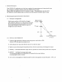
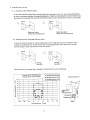
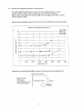
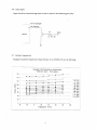
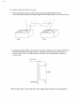
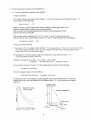
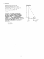
KOALA IR TRIANGULATION SENSOR
USER MANUAL
K-Team S.A.
Version 1.0
Lausanne, 30 Novembre 2001
Documentation author:
K-Team S.A.
Chemin du Vuasset, CP 111
1028 Préverenges
Switzerland
[email protected]
http://www.k-team.com
Trademark Acknowledgements:
GP2D02 : Sharp.
Matlab: The Mathworks.
LabView: National Instruments.
Koala: K-Team S.A.
NOTICE:
•
The contents of this manual are subject to change without notice.
•
The information contained in this manual is, to the best of our knowledge, complete, accurate and
up to date. However, K-Team can assume no responsibility or liability for any inaccuracies or
omissions. Should any errors be detected please inform K-Team S.A.
Koala IR Triangulation Sensor USER MANUAL
2
Contents
1. INTRODUCTION...................................................................................................................................................................... 3
1.1. GENERALITIES....................................................................................................................................................................... 3
2. SONAR SPECIFICATIONS..................................................................................................................................................... 4
2.1. SONAR PINOUT............................................................................................................ ERROR! BOOKMARK NOT DEFINED.
3. GETTING STARTED ............................................................................................................................................................... 4
3.1. TESTING ...................................................................................................................... ERROR! BOOKMARK NOT DEFINED.
3.2. CALIBRATION .............................................................................................................. ERROR! BOOKMARK NOT DEFINED.
4. USING THE SONAR SENSORS ............................................................................................................................................. 4
4.1. USING THE SERIAL PORT ...................................................................................................................................................... 4
4.2. USING A CUSTOM C PROGRAM ............................................................................................................................................ 5
5. SOFTWARE EXAMPLE.......................................................................................................................................................... 5
1. Introduction
Thanks for choosing the Infrared Triangulation Sensor extension for Koala! This extension for Koala
greatly expands the obstacle detection capability of the Koala.
The package includes 4 Sharp GP2D02 compact, high sensitive distance measuring sensor. These
sensors can detect obstacles over a wide range from 10cm to 80cm, and complement the Koala built-in
infrared proximity sensors, which have a range from 5cm to 20cm. Koala can thus use the sonar
sensors for exploring wide-open areas, while using the infrared sensors as a “virtual bumper” and for
negotiating tight spaces.
1.1. Generalities
For the latest information on K-Team products, please visit http://www.k-team.com
Safety Precautions
•
•
•
•
•
•
Check the operating voltage of all components before operation. It must correspond to your local
power supply. The operating voltage is indicated on the nameplate of the power supply.
Don't plug or unplug any connector when the system is switched ON.
All connections (including adding or disconnecting extensions) must be made when the robot and
the interface are switched OFF, otherwise damage can occur.
Switch OFF the robot and any additional power supplies if you will not use them for more than a
day.
Do not open the robot unless explicitly directed to do so by K-Team technicians. Perform this
operation by carefully following the instructions given in appendix C.
Do not manually force any mechanical parts, such as pushing the robot and forcing its wheels.
If you have any questions or problems concerning the robot, please contact your Koala dealer.
Recycling
Koala IR Triangulation Sensor USER MANUAL
3
Think about the end of life of your robot! Parts of the robot can be recycled and it is important to do
so. It is for instance important to keep batteries out of the solid waste stream. When you throw away a
battery, it eventually ends up in a landfill or municipal incinerator. These batteries can contribute to
the toxicity levels of landfills or incinerator ash. By recycling the batteries through battery recycling
programs, you can help to create a cleaner and safer environment for generations to come. For these
reasons please take care to recycle your robot and robot accessories at the end of its life cycle, by for
instance sending back the old equipment to the manufacturer or to your local dealer.
Thanks for your contribution to a cleaner environment!
2. Specifications
The Koala IR Triangulation package includes four GP2D02 (cf in attachment GP2D02 Specifications
and GP2D02/05 Application Note). Two of them are on the right and left side of the Koala. The two
others are in front of the Koala where they replace two Infrared Koala Sensors, leaving 14 Infrared
Sensors on the Koala.
Technical Aspect
Output
Range
Refresh Rate
Details
8-bit
10cm to 80cm
1000Hz
3. Getting Started
Please use the following procedure to test the sensors:
1. Connect your PC to the Koala DCE serial port (item 4, p 4 of Silver Koala User Manual).
2. Check the active serial line jumper (item 8, p 5 of Silver Koala User Manual).
3. Connect to the Koala serial port using a terminal program set to 38400, 8bit, no flow control, no
parity, 2 stop bits.
4. Ensure the Koala is in mode 3, and then turn on the robot. A startup message should appear on the
terminal screen (see Koala documentation for more details).
5. Type V then return. You should see the following answer:
v,side_left,front_left,side_right,front_left
where side_left, front_left, side_right and front_left are 8bit output by IR sensors.
4. Using the Sonar Sensors
There are two ways you can read the IR triangulation sensors: via a serial line using the Koala SerCom
protocol, or by writing a custom C program loaded into the robot’s memory.
4.1. Using the Serial Port
The protocol command V allow to read the triangulation sensor. Simply connect to the Koala’s serial
port with a terminal program set to 38400 8 bit, no flow control, no parity, 2 stop bits. Make sure the
Koala is in mode 3 and turn on the robot (see the Koala documentation for more details). After the
startup message is displayed, you can read the 4 sensors directly using the command V.
Koala IR Triangulation Sensor USER MANUAL
4
This simple serial protocol is very flexible, and lets you write control routines using any application
that supports serial port communication (e.g. Matlab, LabView, etc.). You do, of course, need a serial
cable connected to the robot at all times, or you may use a radio modem to transmit the commands to
the host computer.
4.2. Using a Custom C Program
For the ultimate in speed and flexibility, you can write a custom C application compiled for the Koala
and stored in its onboard flash memory. To read the analog inputs you must use the command
sens_get_sharp_value(input) which returns a 8bit value delivered by the sensor.. Please
see the example file sonar.c given in section 5 for more details.
For information on how to compile programs for Koala, please see the K-Team website
(www.k-team.com) for more information.
5. Software Example
/*
; Test Sharp.
; ===========
;-----------------------------------------------------------------------; Author:
Jaquet C.
30/07/2000
; Modifs:
;
; Project: Koala
; Goal:
Test SHARP
;
; [email protected]
;
;-----------------------------------------------------------------------*/
#include
#include
#include
#include
<sys/kos.h>
<stdlib.h>
<stdio.h>
<string.h>
/*
* Process 0
* ^^^^^^^^^
*
* This process changes the state of the LED 0
* every 500 ms.
*
*/
static void process_0 ()
{
for (;;)
{
tim_suspend_task (5000);
var_change_led (0);
}
}
/*
* Process 1
* ^^^^^^^^^
Koala IR Triangulation Sensor USER MANUAL
5
*
*
*
*/
void process_1()
{
printf("Test SHARP proximity sensors\r\n");
printf("----------------------------\r\n\n");
for (;;)
{
printf("Sharp value : %3.3li, %3.3li, %3.3li, %3.3li.\r\n"
, sens_get_sharp_value(0), sens_get_sharp_value(1)
, sens_get_sharp_value(2), sens_get_sharp_value(3));
tim_suspend_task(200);
}
kill_task(tim_get_id());
}
/*
* MAIN
* ====
*
* - Initialise the used managers: tim & bios are initialised at the start-up.
* - Launch all the processes.
* - Kill the "main". At this moment only the launched processes are executed.
*
*/
void main(void)
{
uint32
vIDProcess[3];
int32 status;
/*
--------------------------|------------------------------------------------|
*/
static char p r N a m e _ 0 [ ]
Rev. 1.00\r\n";
static char p r N a m e _ 1 [ ]
Rev. 1.00\r\n";
=
"User
0
process,
EF-98
=
"User
1
process,
EF-98
com_reset();
tim_reset();
sens_reset();
status = install_task(prName_0, 800, process_0);
if (status == -1) exit(0);
vIDProcess[0] = (uint32)status;
status = install_task(prName_1, 800, process_1);
if (status == -1) exit(0);
vIDProcess[1] = (uint32)status;
}
Koala IR Triangulation Sensor USER MANUAL
6
Appendix A :Specification of GP2D02 and
Application Notes
Koala IR Triangulation Sensor USER MANUAL
7
GP2D02
GP2D02
Compact, High Sensitive Distance
Measuring Sensor
■ Features
■ Outline Dimensions
connection to microcomputer
3. Low dissipation current at OFF-state
φ3
Emitting portion
.2
Detecting portion
±0
.15
R4
2❈ 4.5 ± 0.2
4
(dissipation current at OFF-state : TYP. 3 µA)
(Unit : mm)
MAX.0.8
2-
2-8
12
14
1. Impervious to color and reflectivity of reflective object
2. High precision distance measurement output for direct
❈ 20 ± 0.2
29
37
4. Capable of changing of distance measuring range
14.4
Block Diagram
4
1
2
3
4
2-1
1
JAPAN SOLDERLESS
TERMINAL MSG. CO.
made connector (S4B-ZR)
2 - 15.4
2 - 1.5
2.7
through change the optical portion (lens)
GND
Vin
VCC
Vout
The dimensions marked with ❈ are described
as the dimensions of lens center position.
3 : VCC
1 : GND
VCC
■ Applications
Reg
1. Sanitary sensors
2. Human body sensors for consumer products such as
VCC
12kΩ
Control circuit
Signal processing
circuit
electric fans and air conditioners
3. Garage sensors
* PSD : Position Sensitive Detector
Light detector (PSD*)
LED drive circuit
IR LED
VCC
Reflective object
■ Absolute Maximum Ratings
Parameter
Supply voltage
*1
Input terminal voltage
Output terminal voltage
Operating temperature
Storage temperature
(Ta=25˚C, VCC =5V)
Symbol
Rating
V CC
- 0.3 to + 10
- 0.3 to + 3
V in
BVO
- 0.3 to + 10
- 10 to + 60
T opr
- 40 to + 70
T stg
Unit
V
V
V
˚C
˚C
*1 Open drain operation input
■ Operating Supply Voltage
Symbol
V CC
:
:
:
:
Rating
4.4 to 7
Unit
V
“ In the absence of confirmation by device specification sheets, SHARP takes no responsibility for any defects that occur in equipment using any of SHARP's devices, shown in catalogs,
data books, etc. Contact SHARP in order to obtain the latest version of the device specification sheets before using any SHARP's device.”
4 : Vout
2 : Vin
(Control
signal
input)
GP2D02
■ Electro-optical Characteristics
Parameter
Distance measuring range
Output terminal voltage
Distance characteristics of output
Dissipation current
(Ta=25˚C,Vcc=5V)
Symbol
∆L
V OH
V OL
D
∆D
ICC
I off
I vin
at operating
at OFF-state
Vin terminal current
Conditions
MIN.
TYP.
*1
10
Output voltage at High
L = 20cm VCC - 0.3
Output voltage at Low
*1
75
L = 80cm, *1
Output change at L=80 cm to 20 cm, *1
48
58
L = 20cm, *1, *2
22
L = 20cm, *1
3
Vin = 0V
- 170
Note) L : Distance to reflective object
DEC : Decimalized value of sensor output (8-bit serial)
*1 Reflective object : White paper (reflectivity : 90%)
*2 Average dissipation current value during distance measuring operation when detecting of input signal, Vin as shown in the timing chart
*3 Vin terminal : Open drain drive input.
Conditions : Vin terminal current at Vin OFF-state : -1 µ A
Vin terminal current at Vin ON-state : 0.3V
■ Test Circuit
1. Test circuit
3
4
8-bit serial output read
2
Vin signal input
Distance measuring sensor
1
2. Vin input signal for measurement
0.1ms
70ms
0.1ms
1.6ms
2ms
MAX.
80
0.3
68
35
8
- 280
Unit
cm
V
V
DEC
DEC
mA
µA
µA
GP2D02
■ Timing Chart
70ms or more
1.5ms or more
0.2ms or less
1ms or more
1.5ms or more
Power OFF
Vin
Output
MSB
LSB
Example of distance measuring output (8-bit)
Fig. 1 Distance Measuring Output vs.
Distance to Reflective Object
White paper : KODAK made gray chart R-27,
white surface (reflectivity : 90%)
Gray paper : KODAK made gray chart R-27,
gray surface (reflectivity : 18%)
Distance measuring output (DEC)
220
200
180
160
White
140
120
100
80
60
Gray
40
20
0
0
20
40
60
80
100
120
Distance to reflective object L (cm)
140
LSB
GP2D02
Fig. 2 Detection Distance vs. Sensing Range
Test Method for Sensing Range Characteristics
100
- X
+ X
Sensing distance : 80 cm
90
70
60
Reflective object
White paper
(reflectivity : 90%)
Sensing distance : 50 cm
50
40
Detecting portion
30
Sensing distance
Detection distance L (cm)
80
Emitting portion
20
10
Sensing distance : 20 cm
0
- 100
- 50
0
50
Sensor
100
Sensing range X (mm)
Fig. 3 Detection Distance vs. Illuminance
100
Test Method for Anti External Disturbing
Light Characteristics
90
Distance to reflective object
Detection distance L (cm)
80
70
60
Reflective object
KODAK made white paper
(reflectivity : 90%)
50cm
50
Illuminance meter
Sensor
40
30cm
30
20
Sunlight
15cm
10
0
0
5000
10000 15000
20000 25000 30000
Illuminance (lx)