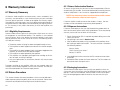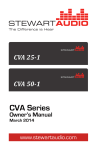
1
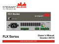
FLX Series POWER STANDBY FLX-80-4 + ~ 100-240VAC 50-60HZ 0.8A #1 - + - + #2 #3 OUTPUT - + #4 - +10V RVC MUTE GND RX TX NETWORK REMOTE/RS232 -+ #1 -+ -+ #2 #3 INPUT -+ #4 Owner’s Manual October 2014 FLX Series www.stewartaudio.com Important Safety Instructions Before using your Stewart Audio Inc. Power Amplifier, please read this Owner’s Manual carefully to ensure optimum trouble-free performance. WARNING: TO REDUCE THE RISK OF ELECTRICAL SHOCK, DO NOT EXPOSE THIS AMPLIFIER TO RAIN OR MOISTURE. DANGEROUS HIGH VOLTAGES ARE PRESENT INSIDE THE ENCLOSURE. DO NOT OPEN THE CABINET. REFER SERVICING TO QUALIFIED PERSONNEL ONLY. CAUTION 3. The amplifier should be situated so that its location and position does not interfere with its proper ventilation. For example, the amplifier must not be placed on a rug, bed, sofa or similar surface that impedes airflow across the chassis. Airflow through the ventilation openings should be unobstructed. 4. This amplifier should not be used near water, for example, near a bathtub, in a wet basement, near a swimming pool, etc. This amplifier is intended to be operated in a controlled indoor environment. 5. Do not place the amplifier near heat sources such as radiators, heat registers, stoves, or other appliances that produce heat. 6. The amplifier should only be connected to 100/240 VAC, 50/60 Hz power supply. Do not defeat the ground or polarization of the power plug. 7. Route power cord and other cables so that they are not likely to be walked on, tripped over or stressed. Pay particular attention to condition of cords and cables at plugs and at the point where they exit the amplifier. To prevent risk of fire or injury, damaged cords and cables should be replaced immediately. 8. Clean the amplifier with a clean, damp cloth. Do not use solvents or abrasive cleaners. Never pour any liquid on the amplifier. 9. When left unused for a long period of time, the power cord should be unplugged form the outlet. RISK OF ELECTRIC SHOCK DO NOT OPEN CAUTION: TO REDUCE THE RISK OF ELECTRIC SHOCK, DO NOT REMOVE COVER (OR BACK). NO USERSERVICEABLE PARTS INSIDE. REFER SERVICING TO QUALIFIED SERVICE PERSONNEL. The lighting bolt within arrowhead symbol, within an equilateral triangle, is intended to alert the user to the presence of un-insulated “dangerous voltage” within the product’s enclosure that may be of sufficient magnitude to constitute a risk of electrical shock to person. The exclamation point within an equilateral triangle, is intended to alert the user to the presence of important operating and maintenance (servicing) instruction in the literature accompanying the appliance. Important Safety Instruction – Please Read Prior to Product Installation. 1. Installation should be performed by a trained and licensed professional to insure safe and lasting operation. 2. All of the safety and operating instructions should be read before the amplifier is installed or operated. Retain these instructions for future reference. All instructions should be followed; all warnings on the amplifier and in the operating instructions should be adhered to. 2 10. Damaged Amplifiers requiring service should be repaired by a qualified service technician when: a. b. c. d. e. The power cord or AC plug has been damaged. Objects have fallen, or liquid has spilled into the unit. The amplifier has been exposed to rain or other moisture. The amplifier does not appear to operate normally or exhibits a marked change in performance. The amplifier has been dropped or the enclosure damaged. 11. The user should not attempt to service the amplifier beyond that described in the operating instructions. All other servicing should be referred to qualified service personnel. 3 Table of Contents Important Safety Instructions······························································ 2 Table of Contents ··············································································· 4 1 Welcome ························································································ 5 1.1 Features ·············································································· 5 1.2 Using this Manual ······························································· 5 2 Setup ······························································································· 6 2.1 Setup Precautions ······························································· 6 2.2 Amplifier Installation ···························································· 6 2.3 Proper Cooling Considerations ··········································· 8 2.4 Input Connections ······························································ 9 2.5 Output Connections ·························································· 12 2.6 Network Connector…………………………………………..15 3 Operation ····················································································· 16 3.1 Operation Precautions ······················································· 16 3.2 Model Configurations………………………………………...16 3.3 Controls, Indicators, and Connectors ································ 17 3.4 Dante ················································································· 22 3.5 Remote Volume Control ···················································· 25 4 Troubleshooting ·········································································· 26 5 Technical Specifications ····························································· 27 6 Warranty Information ·································································· 28 6.1 Warranty Summary ··························································· 28 6.2 Return Procedure ····························································· 28 7 Accessories ················································································ 31 1 Welcome Congratulations on the purchase of your new Stewart Audio FLX Series power amplifier. This amplifier has been designed and built to provide you with years of high-quality audio performance and trouble-free operation. If after reading this manual you should have any questions concerning amplifier installation and operation, please contact your Authorized Stewart Dealer, or you may contact us directly using the contact information provided on the back of this manual. 1.1 Features The FLX Series of amplifiers are the 1st family of half-rack commercial amplifiers on the market offering 320W of power to incorporate integrated DSP. This unique combination of power and features allows these amplifiers to be tailored to the zone, application, room acoustics, and speakers saving time and budget. Your Stewart Audio FLX Series amplifier is the result of years of experience in the design and manufacture of quality amplifiers. As such it provides a combination of performance and operational benefits that simply cannot be found in conventional amplifiers. Dante interface available Integrated DSP for signal routing, filtering, and bridging USB and RS-232 control and configuration Available in both low impedance and constant voltage models Phantom power Made in the USA 1.2 Using this Manual In order to obtain maximum performance from your FLX Series Amplifier, please take time to read this brief owner’s manual and carefully follow the guidelines for connection and operation. 4 This manual provides you with the information necessary to safely install and operate your new FLX Series amplifier in the most common scenarios. If you find yourself requiring additional assistance, please feel free to contact your Authorized Dealer, or you may contact us directly using the contact information provided on the back of this manual. 5 2 Setup 2.1 Setup Precautions Step 4: Bring the two subassemblies together, overlapping the flanges on the inner brackets. Complete assembly by inserting two screws into the front of the pair of inner brackets and two screws to the rear pair of the inner brackets. CAUTION: Before installing your amplifier, make sure that you have read the Important Safety Precautions at the beginning of this manual. 2.2 Amplifier Installation Two rack mounting options are available for the FLX Series amplifiers. A single rack-mount kit provides for installation of a single FLX Series amplifier on a 1RU rack. The dual rack-mount kit provides for the installation of two FLX Series amplifiers side-by-side on a single rack. 2.2.1 Single Rack Mount Kit (Part Number RKMHLF-S) Assembling the single rack mount kit is straightforward. Attach each of the right-angle brackets by inserting the 2 screws through the bracket into the side of the FLX enclosure. Two straight brackets are also provided for the rear of the amplifier. The method of attaching these to the rack will depend on the type of rack you are using. Part Number: RMK-HLF-D CAUTION: Use only the screws provided in mounting brackets to the amplifier. Do not over tighten. 2.2.2 Dual Rack-mount Kit (Part Number RKM-HLF-D) Refer to the figure on the following page when assembling the dual rack mount brackets onto the FLX amplifier. Step 1: Note the position of the captive nuts on the inner brackets. One set must be near the front of one amplifier and the other set near the rear of one amplifier. Step 2: Attach the right-angle brackets to the front of each amplifier and the flat brackets to the rear of each amplifier. Step 3: Attach inner brackets to each amplifier as oriented in step 1. the front of the pair of inner brackets and two screws to the rear pair of the inner brackets. 6 7 2.2.3 Product Dimensions 2.4 Input Connections 8.4in Your FLX Series amplifier is provided with a four (4) removable 3-pin 3.5mm terminal block connectors, one for each local input. This connector will accept both balanced (differential) or unbalanced (singleended) connections, however some modifications must be made for an unbalanced connection. See the next three sections for instructions on connecting your amplifier to its input source. 21.2cm FLX Series 1.7in 4.4cm POWER STANDBY 10.7in 27.2cm 1.7in 4.4cm Side 2.3 Proper Cooling Considerations Because the FLX Series amplifiers are convection cooled with no fans, amplifiers must be given adequate space to allow for proper airflow. Do not stack the amplifiers on top of each other or mount them in a way that other equipment will block airflow through the case. Channels 1 and 2 can be line or mic inputs, with software controlled phantom power available; channels 3 and 4 are line only inputs. 2.4.1 Balanced (Differential) Connections When using a balanced input source and connector, you must ensure that the hot, cold, and ground pins of the connector are matched up to the +, -, and ground pins of the amplifier’s connector respectively. Diagrams have been provided for standard XLR and TRS connectors. Please refer to the manual of your input source in case it does not follow the standard pin-out. Input Connector - + CAUTION: Inadequate airflow to the amplifier can cause the amplifier to overheat and potentially become damaged in the process. Be sure to provide plenty of air space to allow for convection cooling. - + - + - + Female XLR Male TRS - Input Connector - + - + - + - + + + Ground (Shield) 8 9 2.4.2 Unbalanced (Single-ended) Input Connections When using an unbalanced input source and connector, a jumper must be added between the negative (-) terminals and the ground terminals. Once this has been done, the source can be connected to the positive (+) and ground terminals. Please refer to the manual of your input source in case it does not follow the standard pin-out. For your convenience, pre-wired connectors are available for purchase, see the next page for details. Pre-wired single-ended (unbalanced) connectors are available for purchase from Stewart Audio. These will allow for a quicker installation with less room for error when connecting the FLX Series amplifier to an unbalanced source. The summing adapters will properly sum a stereo source for use with the mono input on the rear of the amplifier without causing sound cancellation. Part numbers are found below the diagrams. NOTE: A jumper is required for connecting an unbalanced input. Input Connector Ground (Shield) Male RCA - + - + - + - + + + + Ground (Shield) ADPT-RCA Mono Female RCA A jumper has been added between the negative (-) terminals and ground ADPT-SUMRCA Stereo Female RCA ADPT-SUM35 Stereo Female 3.5mm Input Connector - + - + - + - + R Ground (Shield) + Ground A jumper has been added between the negative (-) terminals and ground (Shield) NOTE: The FLX Series of amplifiers do not accept stereo inputs. Either one side must be selected from the stereo source or an overload-protected Y-cable must be used to sum the left and right channels to mono. It is highly recommended that you purchase the pre-wired connectors on the following page. Damage to source equipment can result from the use of a standard Y-cable. 10 11 2.5 Output Connections 2.5.1 Low Impedance (8Ω) Models Stewart Audio recommends using high-quality, heavy-gauge speaker wire and connectors to send the output signal of your amplifier to the speakers. Use the following table as a guideline when selecting your wire gauge. Distance Wire Gauge Up to 25 ft. 16 AWG 26-40 ft. 14 AWG 41-60 ft. 12 AWG Output Connector + Speaker leads connect by means of removable terminal block connectors supplied with the unit. Strip speaker leads 1/4” and insert into connector observing proper polarity. With a small, flat-blade screwdriver, tighten the screw until the leads are held securely in place. Inspect for possible shorts or broken wires. - + - + - + - - + - + Channel 1 + 2 (Bridged) Output Connector + It is possible (via the DSP Control Software) to bridge two outputs. Thus a four-output FLX 80-4 can be configured for four 80W outputs, two 160W outputs, or one 160W output and two 80W outputs ( a 2.1 configuration). When the amplifier is bridged, the speaker connections differ from when the amplifier unbridged. For example, if outputs 1 and 2 are bridged, the speaker leads are connected to the positive terminal of output 1 and the negative terminal of output 2. The figure below shows proper connections when both pairs of outputs are bridged. - + - - + - + Channel 3 + 4 (Bridged) Speaker Connection Diagram for Bridged Output CAUTION: Do not connect either speaker terminal to ground. This will cause a short circuit which may damage the amplifier, speaker, or both. 2.5.2 High Impedance (Constant Voltage) Models + - Channel 1 12 + - Channel 2 + - Channel 3 + - Because the current flow in constant voltage systems and speakers is much lower than in 8Ω systems, higher gauge (thinner diameter) wire can be used. Please refer to the following chart to choose the appropriate wire gauge for your installation. Channel 4 13 Distance Wire Gauge Up to 500ft 500-1000 ft. Over 1000ft 22 AWG 20 AWG 18 AWG 2.6 Network Connector Speaker leads connect by means of removable 5mm terminal block connectors supplied with the unit. Strip speaker leads 1/4” and insert leads into connector observing proper polarity. With a small, flat-blade screwdriver, tighten the screw until the leads are held securely in place. Inspect for possible shorts or broken wires. NOTE: Class 2 wiring must be used on the speaker terminals to comply with UL requirements.: . An RJ-45 connector is provided on Dante network enabled models. Connect this port to your audio transport network switch or router (see Section 3.4 Dante). Network and cable requirements are available from the Audinate web site at www.audinate.com. All network-enabled FLX amplifiers are shipped from the factory with network input 1 routed to local output 1 (via the internal DSP software mixer). If the FLX model has more than one local output, the corresponding network input is routed to the local output with the same number designation. This can be changed as desired via the DSP Control Center software. CAUTION: Do not connect either speaker terminal to ground. This will cause a short circuit which may damage the amplifier, speaker, or both. CAUTION: The speaker terminals represent a shock hazard as they carry 70.7V and 100V when driven with an audio signal. Disconnect the amplifier from the AC power source when working on these terminals. Output Connector 70V COM 100V 70V COM 100V 70V COM 100V 70V COM 100V + - + Channel 1 Channel 2 = 14 - + - Channel 3 + - Channel 4 Step down transformer at each speaker 15 3.3 Controls, Indicators, and Connectors 3 Operation FLX Series 1. Before use, your amplifier must be configured for proper operation, including input and output wiring hookup. Improper wiring can result in damage to equipment or potentially harm to the operator. Consult Section 2 for setup instructions. 2. Tampering with the circuitry, or making unauthorized changes is not only dangerous but may also violate local regulations. 3. Use care when making connections between the amplifier and the input or output equipment. Using equipment that is not capable of handling the output wattage may lead to permanent damage. NOTE: Stewart Audio will not be held responsible for damage to your FLX Series amplifier or connected equipment if the instructions in this manual are not followed. 3.2 Model Configurations POWER 1 STANDBY 2 FLX-80-4 NETWORK 5 ~ 100-240VAC 50-60HZ 0.8A 3 + #1 - + - + #2 #3 OUTPUT - + 4 #4 - 7 6 +10V RVC MUTE GND RX TX 3.1 Operating Precautions REMOTE/RS232 -+ #1 -+ -+ #2 #3 INPUT 8 -+ #4 1 USB 2.0 Connector 5 Remote Volume Connector - 3.5mm 2 Power/Standby LEDs 6 RS232 Connector - 3.5mm 3 Power Connector - IEC (included) 7 Dante Network Connector - RJ-45 4 Output Connections - 5mm 7 Input Connections - 3.5mm The basic differences between the FLX models are outlined in the table below. FLX 80-4 FLX 80-4 CV Output Power per 40W/80W into Channel 4/8Ω No. local Inputs 80W @ 70/100V FLX 160-2 CV FLX320-1 CV 160W @ 70/100V 320W @ 70/100V 4 balanced (2 mic with phantom power) No. local Outputs 4 unbridged 2 or 3 bridged 4 2 1 No. Network Inputs / Outputs 4/4 4/4 4/4 4/4 There are two possible bridge modes for the FLX80-4 model. When this model is operated in a bridge mode, be sure to review the settings in the matrix mixer to be certain the network inputs(s) is (are) routed to the desired output(s). 16 17 OUTPUT 4 Gain Delay OUTPUT 3 Gain Delay OUTPUT 2 Gain Delay OUTPUT 1 Gain FLX Series amplifiers have 2 front panel LED indicators. The first is the power indicator, which will illuminate when power is supplied to the amplifier. There is no power switch so the unit will remain on continuously when plugged in. The second LED indicator illuminates when the amplifier is in standby (“sleep”) mode. Delay 3.3.1 Indicators NETWORK OUTPUT 4 NETWORK OUTPUT 3 NETWORK OUTPUT 1 NETWORK OUTPUT 2 Limiter EQ 6 Blocks Pink Noise Sine Wave Gain Compressor EQ 3 Blocks Adjustable Pregain NETWORK INPUT 4 EQ Blocks High Pass (1st/2nd Order) Low Pass (1st/2nd Order) Low Shelf High Shelf Peak (PEQ) Notch Compressor EQ 3 Blocks Adjustable Pregain NETWORK INPUT 3 Gain Compressor EQ 3 Blocks Adjustable Pregain NETWORK INPUT 2 Gain Compressor EQ 3 Blocks Adjustable Pregain NETWORK INPUT 1 Gain Gain Compressor EQ 3 Blocks Adjustable Pregain LOCAL INPUT 4 Priority Ducker Compressor EQ 3 Blocks Adjustable Pregain LOCAL INPUT 3 Gain Compressor EQ 3 Blocks Adjustable Pregain LOCAL INPUT 2 Gain Matrix Mixer Trim Limiter EQ 6 Blocks Trim Limiter EQ 6 Blocks Trim EQ 6 Blocks Trim Gain Compressor EQ 3 Blocks The cross-point mixer is shown below. Adjustable Pregain A flow chart of the DSP chain for each input and output is displayed on the following page. All FLX amplifiers have 4 local and, if network enabled, 4 network inputs. The number of outputs depends on the specific model and the mode (bridged or unbridged). LOCAL INPUT 1 FLX Series amplifiers have an integrated digital signal processor (DSP), providing considerable control of the audio signals. A set of DSP functions is available for each signal path. A powerful cross-point mixer provides a means of routing and mixing signals from the various inputs (both local and network) to the network and local outputs. The amplifiers are configured entirely via Stewart Audio’s DSP Control Center software via a USB link. The most current version of the Control Center software can be downloaded via the following link. (http:// www.stewartaudio.com/DSPCC). DSP Control Center manual can be downloaded at http://www.stewartaudio.com/DSPCC. Limiter 3.3.2 Controls 18 19 1 3.3.3 RS-232 Commands An RS–232 port allows remote control of selected amplifier functions. The RS-232 commands are defined in the table below and on the next page. The CHAN is as follows: 0x00 is all channels 0x01 is CH1 0x02 is CH2, etc. The VOL is the attenuation in dB relative to full volume (0 dB). This should be entered as a positive value between 0 and 60 (0x00 to 0x3C Hexidecimal) 3 The PRESET is zero-based in the range 0x00 - 0x09 2 Command Name and Description Hex Command VOLUME UP Increases volume by dB on CHAN1 0x12 0x16 CHAN1 0xdB 0x03 VOLUME DOW1 Decreases volume by dB on CHAN2 0x12 0x17 CHAN1 0xdB 0x03 VOLUME_DISCRETE Sets CHAN1 volume to VOL2 0x12 0x18 CHAN1 VOL2 0x03 VOLUME_STATUS Return CHAN1 volume in the format: 0x06 VOL2 0x0A 0x12 0x07 CHAN1 0x03 FORCE_MUTE_ON Turn mute off for CHAN1 0x12 0x08 CHAN1 0x03 FORCE_MUTE_OFF Turn mute on for CHAN1 0x12 0x09 CHAN1 0x03 MUTE_TOGGLE Toggle mute on CHAN1 0x12 0x10 CHAN1 0x03 MUTE_STATUS Return CHAN1 mute status in the format: 0x12 0x11 CHAN1 0x03 CHANGE_PRESET Change to PRESET3 0x12 0x12 PRESET3 0x03 FIRMWARE_VERSION Returns the current version in the format: 0x02 0xXX 0xYY 0x03 (XX = Version, YY = Revision) 0x12 0x13 0x13 0x03 20 21 3.4 Dante Your network enabled FLX Series amplifier can act as a network breakin / break-out box, as well as an amplifier with local inputs and outputs. Audio signal routing and configuration is done using the Dante Controller software from Audinate at www.audinate.com. All network-enabled FLX amplifiers are shipped from the factory with network input 1 routed to local output 1 (via the internal DSP software mixer). If the FLX model has more than one local output, the corresponding network input is routed to the local output with the same number designation. This can be changed as desired via the DSP Control Center software. Select “Dante Controller” under the Products section. This will require registration for Audinate’s portal and also includes access to the Dante Controller User Manual which should be read for complete configuration instructions. All Stewart Audio products will ship from the factory with the name Ultimo-<MAC>. This can be renamed within the device configuration in the Dante Controller software. 3.4.1 Using Audinate’s Dante Controller Software Transmitters are shown on the top of the matrix while Receivers are shown on the left-hand side. The FLX Series amplifiers include 4 transmitter channels and 4 receive channels. In order to make a connection, click on the matrix node between the appropriate transmitter and receiver. If a connection is successful, it will display a green checkmark. Once Dante Controller has been installed following the instructions in the Dante Controller Software User Manual (www.audinate.com), launch the application to see the connection matrix. Note: All network-enabled FLX amplifiers are shipped from the factory with network input 1 routed to local output 1 (via the internal DSP software mixer). If the FLX model has more than one local output, the corresponding network input is routed to the local output with the same number designation. This can be changed as desired via the DSP Control Center software. 3.4.2 Dante FAQ Q: I am having problems installing or using the Dante Controller Software. A: Please refer to the official documentation available in the Audinate portal where you downloaded the Controller Software. Q: I do not see the FLX Series amplifier showing up on the network? A: All Stewart Audio products are tagged as Ultimo-<MAC_ADDRESS> from the factory. You can find a specific Ultimo device by choosing the device’s MAC address from the list. You can rename this using the 22 23 Dante Controller software. 3.5 Remote Volume Control Q: I routed an audio signal to network input 1 of the FLX amplifier using the Dante Control Center software, but hear no output from the amplifier. FLX Series amplifier volume can be remotely controlled (or muted) via the input on the rear of the amplifier. In addition to the RS-232 connector (Section 3.3.3), an external potentiometer, which can be located wherever convenient, can also control the output volume of all channels. Remote muting is also useful for fire-alarm situations in which all unnecessary sound must be silenced. A: Check the settings in the FLX amplifier matrix mixer (using the DSP Control Center software) to be certain that network input 1 is routed to a local output. NOTE: The remote volume control connector attenuates the signal level from the level set by the DSP and RS-232 settings. It cannot increase the signal level above those settings, nor does it change those settings. NOTE 2: The remote volume control is disabled when the USB cable is connected to the device even if a connection has not been established between the DSP Control Center and the device. Remove the USB connector to use the remote volume control. In order to remotely control the volume of the unit, a 10k-ohm, linear taper potentiometer should be placed between the +10V pin and the GND (Ground) pin on the rear of the unit with its wiper on the RVC pin. The volume will be determined by the selected resistance on the potentiometer, the greater the resistance the louder the volume. The amplifier can be remotely muted by making a connection between the GND pin and the MUTE pin. No power should be applied to these pins, simply a contact connection. 24 25 4 Troubleshooting Problem: Power indicator does not turn on. Procedure: Check that the amplifier is plugged into a live outlet. After you have ensured that it is not a power issue, disconnect any speakers. If the amplifier turns on after a few seconds delay, then the problem is in the output connection. Check wiring and speakers for short circuits. 5 Technical Specifications Power Output FLX80-4 80/40W x 4 @ 4/8Ω FLX80-4 CV 80W x4 @ 70.7V/100V FLX160-2 CV 160W x 2 @ 70.7V/100V FLX320-1 CV 320W x 1 @n 70.7V/100V Frequency Response (+0, -3 dB) 20Hz-20kHz 4/8Ω 100Hz-20kHz Constant Voltage THD+N (@ full output power) <0.1% Signal to Noise Ratio >100 dB Input Sensitivity 1V (0 dBV) Input Impedance (Balanced/ Unbalanced/Phantom) 7.2 kΩ / 3.6kΩ / 1.2kΩ Problem: Amplifier overheats and/or shuts off. External Mute Contact closure Procedure: Review Section 2.3 on proper cooling procedures. Ensure input signal levels are 1 Vrms or less. Overdriving the amplifier for extended periods of time can cause a thermal shutdown. Power Consumption: Idle; 1/8 Draw TBD Amplifier Class D Remote Volume 0-10V External Mute Contact closure Input Connectors 3.5mm terminal block Output Connectors 5mm terminal block Dante Network Connector RJ-45 LED Indicators Power, Standby Controls USB, RS-232, RVC Power Supply Internal 110/240VAC 50-60Hz Cooling Convection-Cooling Construction Aluminum Chassis Mounting Rack-mountable Dimensions (height, width, length) 1.75”, 8.4”, 10.7” Weight 5.5 lbs max (varies by model)) Problem: No output on one or more channels; Power indicator is lit. Procedure: Check that cross-point mixer settings are correct. Check that input and output connections are secure. Problem: Output sound is distorted or cracking. Procedure: Check all cables for damage or loose connections and reduce the gain on the input signal at the mixer. Replace the cables and loudspeakers temporarily to see if this resolves the problem. If problem still exists, contact your Authorized Dealer for service. 26 Stewart Audio reserves the rate to change features and specifications without notice. 27 6 Warranty Information 6.1 Warranty Summary All Stewart Audio amplifiers and accessories, unless excluded in this summary, are covered by a 3-year limited warranty on parts and labor from the data of purchase. In order to be eligible for warranty repairs, the amplifiers and accessories must have been purchased through an authorized Stewart Audio dealer and submitted by the original purchaser. This warranty is only valid in the country in which the amplifier was purchased. 6.1.1 Eligibility Requirements. Stewart Audio warrants against all malfunctions which come as a result of component or manufacturer defect. The amplifier is also covered from all failures which arise during the warranty period (3 years from date of purchase) that are not a result of misuse. The following actions will void your warranty: The power cord or AC plug has been damaged through misuse. The amplifier has been exposed to moisture or extreme temperatures. The amplifier has been dropped, items have been dropped on the amplifier, or the enclosure has been damaged. The amplifier has been opened by the operator. The amplifier was improperly packaged when sending to the factory for repair, resulting in damage. Any of the precautions or instructions found in this manual were not followed. Damages resulting to the amplifier which are not covered under this warranty can be factory-repaired at cost to the customer. Use the contact information below to initiate the repair process. 6.2 Return Procedure This section includes the return procedures which must be followed in order to prevent processing delay or cost to the customer. Please read the entire section before contacting Stewart Audio for returns. 28 6.2.1 Return Authorization Number All returns to the factory for service must be accompanied by a Return Authorization (RA) number. One can be obtained by contacting Stewart Audio at (209) 588-8111 or via e-mail at [email protected]. NOTE: Any defective products received without an RA number will be returned to sender at their expense. If Stewart Audio is unable to contact the sender in 14 days, the merchandise will be considered scrap and may be disposed of. 6.2.2 Shipment Instructions If Stewart Audio requests that you ship the defective product back to their service center, please refer to the guide below. To ensure prompt warranty service, be sure to follow all instructions. 1. Return Authorization (RA) is required for product being sent to the factory for service. 2. See packing instructions in Section 6.2.3. 3. Ship the defective product using a method which provides for order tracking or order confirmation. The service center is located at the following address: Stewart Audio 14335 Cuesta Court Suite C Sonora, CA 95370 4. Use a bold black marker and write the RA number on three sides of the box. 5. Record the RMA number for future reference. The RA number can be used to check the repair status. 6.2.3 Packaging Instructions Should Stewart Audio request that you ship your product to their service center, these instructions must be followed in order to ensure safe delivery. If they are not followed, Stewart Audio assumes no responsibility for damaged goods and/or accessories that are sent with your unit. 29 6.2.3 Packaging Instructions (cont.) 1. Please write the RA number on three sides of the box. Include the Stewart Audio RA number inside the box and a brief description of the problem. 2. You will be advised during the RA process what accessories should be included with the amplifier (Power supplies, connectors, cords, etc.). This is dependent on the failure assessment. 3. When shipping your amplifier, it is important that it has adequate protection. We recommend you use the original packing material when returning the product for repair. If you do not have the original box, see number 4. 4. If you provide your own shipping pack, the minimum recommended requirements for materials are as follows: a. 275 P.S.I. burst test, Double-Wall carton that allows for 2inch solid Styrofoam on all six sides of unit or 3 inches of plastic bubble wrap on all six sides of unit. b. Securely seal the package with an adequate carton sealing tape. c. Do not use light boxes or “peanuts”. NOTE: Damage caused by poor packaging will not be covered under warranty. 6.2.4 Estimate Approval An estimate for all non-warranty repairs will be provided to the customer once the unit has been shipped to the factory. The customer is responsible to approve this estimate within 7 days. If the repairs are not approved within 14 days, Stewart Audio reserves the right to consider the unit scrap and may discard it. 6.2.5 Payment of Non-Warranty Repairs Payment for non-warranty repairs must be submitted to Stewart Audio before the product will be returned to the customer. 7 Accessories The following accessories are available from Stewart Audio for your amplifier. Mounting Brackets RKM-HLF-S Single rack-mount kit for FLX Series amplifiers RKM-HLF-D Dual rack-mount kit for FLX Series amplifiers Connection Adapters ADPT-RCA Mono Female RCA to male 3.5mm terminal block. ADPT-SUMRCA Stereo Female RCA to male 3.5mm terminal block.. ADPT-SUM35 Stereo Female 3.5mm to male 3.5mm terminal block. Wall Plates WP-RVC-B Wallplate with 10k potentiometer and knob for remote volume control (Black) WP-RVC-A Wallplate with 10k potentiometer and knob for remote volume control (Aluminum) To purchase these accessories or to see the full Stewart Audio product lineup, visit us at: www.stewartaudio.com For Your Record In the spaces provided below, record the model and serial number located at the rear of your amplifier. Model No. ________________________________________ Serial No. _________________________________________ Purchase Date _____________________________________ 30 31