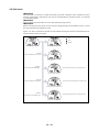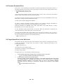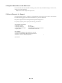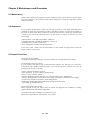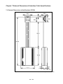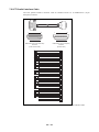
1
To our customers,
Old Company Name in Catalogs and Other Documents
On April 1st, 2010, NEC Electronics Corporation merged with Renesas Technology
Corporation, and Renesas Electronics Corporation took over all the business of both
companies. Therefore, although the old company name remains in this document, it is a valid
Renesas Electronics document. We appreciate your understanding.
Renesas Electronics website: http://www.renesas.com
April 1st, 2010
Renesas Electronics Corporation
Issued by: Renesas Electronics Corporation (http://www.renesas.com)
Send any inquiries to http://www.renesas.com/inquiry.
Notice
1.
2.
3.
4.
5.
6.
7.
All information included in this document is current as of the date this document is issued. Such information, however, is
subject to change without any prior notice. Before purchasing or using any Renesas Electronics products listed herein, please
confirm the latest product information with a Renesas Electronics sales office. Also, please pay regular and careful attention to
additional and different information to be disclosed by Renesas Electronics such as that disclosed through our website.
Renesas Electronics does not assume any liability for infringement of patents, copyrights, or other intellectual property rights
of third parties by or arising from the use of Renesas Electronics products or technical information described in this document.
No license, express, implied or otherwise, is granted hereby under any patents, copyrights or other intellectual property rights
of Renesas Electronics or others.
You should not alter, modify, copy, or otherwise misappropriate any Renesas Electronics product, whether in whole or in part.
Descriptions of circuits, software and other related information in this document are provided only to illustrate the operation of
semiconductor products and application examples. You are fully responsible for the incorporation of these circuits, software,
and information in the design of your equipment. Renesas Electronics assumes no responsibility for any losses incurred by
you or third parties arising from the use of these circuits, software, or information.
When exporting the products or technology described in this document, you should comply with the applicable export control
laws and regulations and follow the procedures required by such laws and regulations. You should not use Renesas
Electronics products or the technology described in this document for any purpose relating to military applications or use by
the military, including but not limited to the development of weapons of mass destruction. Renesas Electronics products and
technology may not be used for or incorporated into any products or systems whose manufacture, use, or sale is prohibited
under any applicable domestic or foreign laws or regulations.
Renesas Electronics has used reasonable care in preparing the information included in this document, but Renesas Electronics
does not warrant that such information is error free. Renesas Electronics assumes no liability whatsoever for any damages
incurred by you resulting from errors in or omissions from the information included herein.
Renesas Electronics products are classified according to the following three quality grades: “Standard”, “High Quality”, and
“Specific”. The recommended applications for each Renesas Electronics product depends on the product’s quality grade, as
indicated below. You must check the quality grade of each Renesas Electronics product before using it in a particular
application. You may not use any Renesas Electronics product for any application categorized as “Specific” without the prior
written consent of Renesas Electronics. Further, you may not use any Renesas Electronics product for any application for
which it is not intended without the prior written consent of Renesas Electronics. Renesas Electronics shall not be in any way
liable for any damages or losses incurred by you or third parties arising from the use of any Renesas Electronics product for an
application categorized as “Specific” or for which the product is not intended where you have failed to obtain the prior written
consent of Renesas Electronics. The quality grade of each Renesas Electronics product is “Standard” unless otherwise
expressly specified in a Renesas Electronics data sheets or data books, etc.
“Standard”:
8.
9.
10.
11.
12.
Computers; office equipment; communications equipment; test and measurement equipment; audio and visual
equipment; home electronic appliances; machine tools; personal electronic equipment; and industrial robots.
“High Quality”: Transportation equipment (automobiles, trains, ships, etc.); traffic control systems; anti-disaster systems; anticrime systems; safety equipment; and medical equipment not specifically designed for life support.
“Specific”:
Aircraft; aerospace equipment; submersible repeaters; nuclear reactor control systems; medical equipment or
systems for life support (e.g. artificial life support devices or systems), surgical implantations, or healthcare
intervention (e.g. excision, etc.), and any other applications or purposes that pose a direct threat to human life.
You should use the Renesas Electronics products described in this document within the range specified by Renesas Electronics,
especially with respect to the maximum rating, operating supply voltage range, movement power voltage range, heat radiation
characteristics, installation and other product characteristics. Renesas Electronics shall have no liability for malfunctions or
damages arising out of the use of Renesas Electronics products beyond such specified ranges.
Although Renesas Electronics endeavors to improve the quality and reliability of its products, semiconductor products have
specific characteristics such as the occurrence of failure at a certain rate and malfunctions under certain use conditions. Further,
Renesas Electronics products are not subject to radiation resistance design. Please be sure to implement safety measures to
guard them against the possibility of physical injury, and injury or damage caused by fire in the event of the failure of a
Renesas Electronics product, such as safety design for hardware and software including but not limited to redundancy, fire
control and malfunction prevention, appropriate treatment for aging degradation or any other appropriate measures. Because
the evaluation of microcomputer software alone is very difficult, please evaluate the safety of the final products or system
manufactured by you.
Please contact a Renesas Electronics sales office for details as to environmental matters such as the environmental
compatibility of each Renesas Electronics product. Please use Renesas Electronics products in compliance with all applicable
laws and regulations that regulate the inclusion or use of controlled substances, including without limitation, the EU RoHS
Directive. Renesas Electronics assumes no liability for damages or losses occurring as a result of your noncompliance with
applicable laws and regulations.
This document may not be reproduced or duplicated, in any form, in whole or in part, without prior written consent of Renesas
Electronics.
Please contact a Renesas Electronics sales office if you have any questions regarding the information contained in this
document or Renesas Electronics products, or if you have any other inquiries.
(Note 1) “Renesas Electronics” as used in this document means Renesas Electronics Corporation and also includes its majorityowned subsidiaries.
(Note 2) “Renesas Electronics product(s)” means any product developed or manufactured by or for Renesas Electronics.
User’s Manual
PC7501
User’s Manual
Emulator for M16C Family
Rev.4.00 2009.08
Notes regarding these materials
1.
2.
3.
4.
5.
6.
7.
8.
9.
10.
11.
12.
13.
This document is provided for reference purposes only so that Renesas customers may select the appropriate
Renesas products for their use. Renesas neither makes warranties or representations with respect to the
accuracy or completeness of the information contained in this document nor grants any license to any intellectual
property rights or any other rights of Renesas or any third party with respect to the information in this document.
Renesas shall have no liability for damages or infringement of any intellectual property or other rights arising out
of the use of any information in this document, including, but not limited to, product data, diagrams, charts,
programs, algorithms, and application circuit examples.
You should not use the products or the technology described in this document for the purpose of military
applications such as the development of weapons of mass destruction or for the purpose of any other military
use. When exporting the products or technology described herein, you should follow the applicable export
control laws and regulations, and procedures required by such laws and regulations.
All information included in this document such as product data, diagrams, charts, programs, algorithms, and
application circuit examples, is current as of the date this document is issued. Such information, however, is
subject to change without any prior notice. Before purchasing or using any Renesas products listed in this
document, please confirm the latest product information with a Renesas sales office. Also, please pay regular
and careful attention to additional and different information to be disclosed by Renesas such as that disclosed
through our website. (http://www.renesas.com)
Renesas has used reasonable care in compiling the information included in this document, but Renesas
assumes no liability whatsoever for any damages incurred as a result of errors or omissions in the information
included in this document.
When using or otherwise relying on the information in this document, you should evaluate the information in light
of the total system before deciding about the applicability of such information to the intended application.
Renesas makes no representations, warranties or guaranties regarding the suitability of its products for any
particular application and specifically disclaims any liability arising out of the application and use of the
information in this document or Renesas products.
With the exception of products specified by Renesas as suitable for automobile applications, Renesas products
are not designed, manufactured or tested for applications or otherwise in systems the failure or malfunction of
which may cause a direct threat to human life or create a risk of human injury or which require especially high
quality and reliability such as safety systems, or equipment or systems for transportation and traffic, healthcare,
combustion control, aerospace and aeronautics, nuclear power, or undersea communication transmission. If you
are considering the use of our products for such purposes, please contact a Renesas sales office beforehand.
Renesas shall have no liability for damages arising out of the uses set forth above.
Notwithstanding the preceding paragraph, you should not use Renesas products for the purposes listed below:
(1) artificial life support devices or systems
(2) surgical implantations
(3) healthcare intervention (e.g., excision, administration of medication, etc.)
(4) any other purposes that pose a direct threat to human life
Renesas shall have no liability for damages arising out of the uses set forth in the above and purchasers who
elect to use Renesas products in any of the foregoing applications shall indemnify and hold harmless Renesas
Technology Corp., its affiliated companies and their officers, directors, and employees against any and all
damages arising out of such applications.
You should use the products described herein within the range specified by Renesas, especially with respect to
the maximum rating, operating supply voltage range, movement power voltage range, heat radiation
characteristics, installation and other product characteristics. Renesas shall have no liability for malfunctions or
damages arising out of the use of Renesas products beyond such specified ranges.
Although Renesas endeavors to improve the quality and reliability of its products, IC products have specific
characteristics such as the occurrence of failure at a certain rate and malfunctions under certain use conditions.
Please be sure to implement safety measures to guard against the possibility of physical injury, and injury or
damage caused by fire in the event of the failure of a Renesas product, such as safety design for hardware and
software including but not limited to redundancy, fire control and malfunction prevention, appropriate treatment
for aging degradation or any other applicable measures. Among others, since the evaluation of microcomputer
software alone is very difficult, please evaluate the safety of the final products or system manufactured by you.
In case Renesas products listed in this document are detached from the products to which the Renesas products
are attached or affixed, the risk of accident such as swallowing by infants and small children is very high. You
should implement safety measures so that Renesas products may not be easily detached from your products.
Renesas shall have no liability for damages arising out of such detachment.
This document may not be reproduced or duplicated, in any form, in whole or in part, without prior written
approval from Renesas.
Please contact a Renesas sales office if you have any questions regarding the information contained in this
document, Renesas semiconductor products, or if you have any other inquiries.
Regulatory Compliance Notices
European Union regulatory notices on Electromagnetic compatibility
CE Certifications:
This product complies with the following European EMC standards.
・ EMC Directive 2004/108/EC
EN 55022 Class A
WARNING: This is a Class A product. In a domestic environment this product may cause radio
interference in which case the user may be required to take adequate measures.
EN 55024
Information for traceability:
・Authorised representative
Name:
Renesas Technology Corp.
Address:
Nippon Bldg., 2-6-2, Ote-machi, Chiyoda-ku, Tokyo 100-0004, Japan
・Manufacturer
Name:
Renesas Solutions Corp.
Address:
Nippon Bldg., 2-6-2, Ote-machi, Chiyoda-ku, Tokyo 100-0004, Japan
・Person responsible for placing on the market
Name:
Renesas Technology Europe Limited European Headquaters
Address:
Dukes Meadow, Millboard Road, Bourne End, Buckinghamshire, SL8 5FH,
U.K.
United States Regulatory notices on Electromagnetic compatibility
FCC Certifications:
This equipment has been tested and found to comply with the limits for a Class A digital device,
pursuant to Part 15 of the FCC Rules. These limits are designed to provide reasonable protection
against harmful interference when the equipment is operated in a commercial environment. This
equipment generates, uses, and can radiate radio frequency energy and, if not installed and used in
accordance with the instruction manual, may cause harmful interference to radio communications.
Operation of this equipment in a residential area is likely to cause harmful interference in which case
the user will be required to correct the interference at his own expense.
This device complies with Part 15 of the FCC Rules. Operation is subject to the following two
conditions: (1) this device may not cause harmful interference, and (2) this device must accept any
interference received, including interference that may cause undesired operation.
CAUTION: Changes or modifications not expressly approved by the party responsible for compliance could
void the user's authority to operate the equipment.
( 3 / 46 )
Preface
The PC7501 system is designed for use with Renesas M16C Family MCUs. The PC7501 system is
configured with the emulator PC7501, an emulation probe M3xxxxTx-EPB, an emulator debugger
M3T-PDxxF, and a host machine.
This user's manual describes the emulator PC7501 centering around specifications and an
explanation of how to set up your PC7501 system. For details about emulation probe
M3xxxxTx-EPB and emulator debugger M3T-PDxxF, refer to each user's manual (or Online Help)
of them.
To check the components of this product, refer to "2.1 Packing List" (P.13). If there is any
suggestion, opinion or question about this product, please contact your local distributor.
To Use the Product Properly
Precautions for Safety
• Either in the PC7501 user's manual or on the product, several icons are used to
insure proper handling of this product and also to prevent injuries to you or other
persons, or damage to your properties.
• Their graphic images and meanings are given in Chapter 1, Precautions for Safety.
Be sure to read this chapter before using the product.
When Using Outside Japan
• When using this product in Europe, the United States, and Canada, be sure to use
the emulator PC7501 and the emulation probe which meet the overseas standards.
( 4 / 46 )
Table of Contents
Chapter 1 Precautions for Safety
1.1 Safety Symbols and Meanings.................................................................................................... 8
WARNING
Warnings for AC Power Supply........................................................................................................ 9
Warnings to Be Taken for This Product ............................................................................................ 9
Warning for Installation .................................................................................................................... 9
Warning for Use Environment .......................................................................................................... 9
CAUTION
Cautions for AC Adapter................................................................................................................. 10
Cautions to Be Taken for This Product ........................................................................................... 10
Caution for AC Power Supply ........................................................................................................ 10
Caution for Installation ................................................................................................................... 10
Caution for Communication Interface ............................................................................................ 10
IMPORTANT:
Note for Installation ........................................................................................................................ 11
Notes for Difference between the Actual MCU and Emulator........................................................ 11
Notes for Unusual Operation .......................................................................................................... 11
Note for Downloading Firmware.................................................................................................... 11
Note for LPT Parallel Interface....................................................................................................... 12
Notes for USB Interface.................................................................................................................. 12
Note for LAN Interface................................................................................................................... 12
Note for Using Memory Expansion and Microprocessor Modes.................................................... 12
Note for Clock ................................................................................................................................ 12
Chapter 2 PC7501 System Configuration
2.1 Packing List .............................................................................................................................. 13
2.2 Outline of PC7501 System Configuration ................................................................................ 13
2.3 PC7501 System Configuration.................................................................................................. 14
2.3.1 Host Machine.............................................................................................................. 14
2.3.2 Emulator PC7501........................................................................................................ 14
2.3.3 Emulation Probe M3xxxxTx-EPB.............................................................................. 14
2.3.4 Emulator Debugger M3T-PDxxF................................................................................ 14
2.4 Specifications............................................................................................................................ 15
Chapter 3 External View
3.1 Names and Functions of Parts on the Upper Panel ................................................................... 17
3.1.1 System Status LEDs.................................................................................................... 18
3.1.2 Target Status LEDs ..................................................................................................... 18
3.2 Names and Functions of Parts on the Rear Panel...................................................................... 19
3.2.1 Interface Selection Switch .......................................................................................... 20
3.2.2 LPT Parallel Interface Connector ............................................................................... 20
3.2.3 USB Interface Connector............................................................................................ 20
3.2.4 LAN Interface Connector ........................................................................................... 20
3.2.5 Power Supply Switch.................................................................................................. 20
3.2.6 DC Power Connector.................................................................................................. 20
3.3 Names and Functions of Parts on the Front Panel .................................................................... 21
3.3.1 System Reset Switch................................................................................................... 21
3.3.2 External Trigger Signal Input/Event Output Connectors ............................................ 22
5 / 46
Chapter 4 Setup
4.1 Connecting AC Adapter ............................................................................................................ 23
4.2 Connecting Host Machine......................................................................................................... 24
4.2.1 Connecting by LPT Parallel Interface......................................................................... 25
4.2.2 Connecting by USB Interface ..................................................................................... 27
4.2.3 Connecting by LAN Interface..................................................................................... 29
4.3 Connecting Emulation Probe M3xxxxTx-EPB......................................................................... 33
4.4 Downloading Firmware ............................................................................................................ 34
4.4.1 When It is Necessary to Download Firmware ............................................................ 34
4.4.2 Downloading the Firmware in Maintenance Mode .................................................... 34
4.5 Self-check ................................................................................................................................. 35
Chapter 5 Troubleshooting
5.1 Emulator PC7501 Cannot Be Powered On ............................................................................... 37
5.2 Interface Connection Error........................................................................................................ 37
5.2.1 LPT Parallel Interface................................................................................................. 37
5.2.2 USB Interface ............................................................................................................. 37
5.2.3 LAN Interface............................................................................................................. 38
5.3 Firmware Download Error ........................................................................................................ 39
5.4 Target Status Error in the Self-check ........................................................................................ 39
5.5 System Status Error in the Self-check....................................................................................... 40
5.6 How to Request for Support...................................................................................................... 40
Chapter 6 Maintenance and Guarantee
6.1 Maintenance.............................................................................................................................. 41
6.2 Guarantee .................................................................................................................................. 41
6.3 Repair Provisions ...................................................................................................................... 41
6.4 How to Make Request for Repair.............................................................................................. 42
Chapter 7 External Dimensions & Interface Cable Specifications
7.1 External Dimensions of the Emulator PC7501 ......................................................................... 43
7.2 LPT Parallel Interface Cable..................................................................................................... 44
6 / 46
Terminology
Some specific words used in this user's manual are defined as follows:
PC7501 system
This means the emulator system built around the emulator PC7501. This emulator system is
configured with the emulator PC7501, an emulation probe M3xxxxTx-EPB, an emulator debugger
M3TPDxxF, and a host machine.
Host machine
This means a personal computer where the emulator debugger M3T-PDxxF runs to control the
emulator PC7501.
Emulation probe
An emulation probe is provided for each MCU Series or MCU and it emulates the operation of
each MCU characteristic. The emulation probe M3xxxxTx-EPB for the emulator PC7501 adopts
the evaluation MCU method of equipping the inside of the emulation probe with evaluation MCU.
Emulator debugger
This means a software tool, M3T-PDxxF to control the emulator PC7501 from a personal
computer through an interface.
Firmware
This means a program that controls the hardware of the PC7501 system by decoding the contents
of communication with the emulator debugger M3T-PDxxF. This program is contained in
EEPROM on the emulator PC7501's inside board.
At startup, the emulator debugger M3T-PDxxF checks the configuration of the emulator PC7501
and emulation probe M3xxxxTx-EPB, and downloads the appropriate firmware when it is necessary.
Target MCU
A target MCU means the MCU you are going to debug.
Target system
A target system means a user's application system using the MCU to be debugged.
#
In this user’s manual, this symbol is used to show active LOW. (e.g. RESET#)
7 / 46
Chapter 1 Precautions for Safety
This chapter describes the handling precautions to be followed when using the emulator PC7501.
For precautions on using the emulator debugger M3T-PDxxF and emulation probe
M3xxxxTx-EPB, refer to each user's manual (or Online Help) of them.
1.1 Safety Symbols and Meanings
WARNING
CAUTION
IMPORTANT:
If the requirements shown in the "WARNING" sentences are
ignored, the equipment may cause serious personal injury or
death.
If the requirements shown in the "CAUTION" sentences are
ignored, the equipment may malfunction.
It means important information on using this product.
In addition to the three above, the following are also used as appropriate.
means WARNING or CAUTION.
Example:
CAUTION AGAINST AN ELECTRIC SHOCK
means PROHIBITION
Example:
DISASSEMBLY PROHIBITED
means A FORCIBLE ACTION
Example:
UNPLUG THE POWER CABLE FROM THE RECEPTACLE.
The following pages describe the symbols "WARNING", "CAUTION", and "IMPORTANT".
8 / 46
WARNING
Warnings for AC Power Supply:
• If the attached AC power cable does not fit the receptacle, do not alter the AC power
cable and do not plug it forcibly. Failure to comply may cause electric shock and/or fire.
• Use an AC power cable which complies with the safety standard of the country.
• Do not touch the plug of the AC power cable when your hands are wet. This may
cause electric shock.
• This product is connected signal ground with frame ground. If your developing
product is transformless (not having isolation transformer of AC power), this may cause
electric shock. Also, this may give an unrepairable damage to this product and your
developing one.
While developing, connect AC power of the product to commercial power through
isolation transformer in order to avoid these dangers.
• If other equipment is connected to the same branch circuit care should be taken not
to overload the circuit. Refer to nameplate for electrical ratings.
• When installing this equipment, insure that a reliable ground connection is
maintained.
• If you smell a strange odor, hear an unusual sound, or see smoke coming from this
product, then disconnect power immediately by unplugging the AC power cable from
the outlet.
Do not use this as it is because of the danger of electric shock and/or fire. In this case,
contact your local distributor.
Warnings to Be Taken for This Product:
• Do not disassemble or modify this product. Personal injury due to electric shock may
occur if this product is disassembled and modified.
• Make sure nothing falls into the cooling fan on the top panel, especially liquids, metal
objects, or anything combustible.
Warning for Installation:
• Do not set this product in water or areas of high humidity. Make sure that the product
does not get wet. Spilling water or some other liquid into the product may cause
unrepairable damage.
Warning for Use Environment:
• This equipment is to be used in an environment with a maximum ambient
temperature of 35°C. Care should be taken that this temperature is not exceeded.
9 / 46
CAUTION
Cautions for AC Adapter:
• Use only the AC adapter included in this product package.
• The included AC adapter is for PC7501. Do not use it for other product.
• Before installing this equipment or connecting it to other equipment, disconnect the AC
power cable from its outlet to prevent injury or accident.
• The DC plug on the included AC adapter has the below polarity.
• The included AC adapter has no power supply switch. The AC adapter is always
active while connecting the AC power cable. Check if the power is supplied by the LED
of AC adapter.
Cautions to Be Taken for This Product:
• Use caution when handling this product. Be careful not to apply a mechanical shock.
• Do not touch the connector pins of the emulation probe and the interface connector
pins directly with your hand.
• Do not pull the main unit by the probe of the emulation probe or the flexible cable
which are connected to this product.
• Excessive flexing or force of the flexible cable for connecting this product to the
emulation probe may break connector.
• Do not use inch-size screws for this equipment. The screws used in this equipment
are all ISO type (meter-size) screws. When exchanging screws, use same type screws
as equipped before.
Caution for AC Power Supply:
• When installing or connecting this product with other equipment, shut down AC power
or disconnect the AC power cord from the equipment to prevent personal injury or
damage to the equipment.
Caution for Installation:
• When in use do not place the emulator PC7501 on its side.
Caution for Communication Interface:
• Always make sure that the emulator PC7501's interface selection switch and the
emulator debugger M3T-PDxxF's interface settings are matched.
10 / 46
IMPORTANT
Note for Installation:
• The emulator PC7501 does not operate stand-alone. It must always be connected
with the emulation probe M3xxxxTx-EPB before you can execute the self-check or
download firmware.
Notes for Difference between the Actual MCU and Emulator:
• Emulator operation differs from that of a mask MCU, as listed below:
(1) Reset conditions
(2) Initial values of internal resource data at power-on
(3) Internal RAM and ROM capacities
(4) A-D converter characteristics when using an emulation probe in the evaluation MCU
method.
• Therefore, always be sure to evaluate your system with an evaluation MCU (OTP,
EPROM or flash version). Also, be sure to perform board-mounted evaluation with CS
(Commercial Sample) version MCU to make final confirmation of device operation
before starting mask production.
Notes for Unusual Operation:
• Do not turn off the power when executing the self-check or downloading firmware. If
the emulator PC7501 is powered off in the middle of a process, it will become unable to
start up normally. In cases when the power is inadvertently shut off, re-execute the
self-check or downloading.
• If the self-check does not terminate normally (except for target status errors), the
emulator PC7501 can be faulty. In such a case, contact your local distributor.
• If the emulator PC7501 malfunctions due to external interference or some other
causes, follow the steps given below.
(1) Press the system reset switch located on the front panel of the emulator PC7501.
(2) If the emulator PC7501 does not return to the normal operation despite the step (1)
above, turn off the power supply switch of the emulator PC7501, and turn it on again.
Note for Downloading Firmware:
• Download firmware as described in "4.4 Downloading Firmware" (P.34) when:
(1) you have set up the emulator PC7501 for the first time.
(2) you have upgraded the firmware.
(3) you have upgraded your emulator debugger.
(4) you have changed your emulator debugger.
(5) you have changed your emulation probe.
11 / 46
IMPORTANT
Note for LPT Parallel Interface:
• With the LPT parallel interface of the PC7501, not all host machines will work and are
guaranteed. According to the specifications and settings of the host machine, some
operation modes of the LPT parallel port cannot be used.
Notes for USB Interface:
• USB interface can not be used with a host machine running Windows 95 or Windows
NT 4.0.
• With the USB interface of the PC7501, not all hardware (such as host machine, USB
devices, USB hub) combinations will work and are guaranteed.
Note for LAN Interface:
• With the LAN interface of the PC7501, not all hardware (such as host machine,
network devices) combinations will work and are guaranteed.
Note for Using Memory Expansion and Microprocessor Modes:
• When using this emulator in memory expansion mode or microprocessor mode, make
sure that RDY# and HOLD# pins are all inactive. Otherwise, the PC7501 can not
startup properly.
Note for Clock:
• When the CLOCK LED does not turn on, check the following conditions:
(1) Immediately after starting up the emulator PC7501
Make sure that the oscillation circuit in the emulator is oscillating normally.
(2) Immediately after starting up the emulator debugger (when the setting in the Init
dialog box has been done)
Make sure that the oscillator that has been specified in the Init dialog box is working
normally.
12 / 46
Chapter 2 PC7501 System Configuration
2.1 Packing List
This product's packing list is shown below.
• Emulator main unit PC7501
• AC adapter (100- 240 V, 50/60 Hz)
• AC power cable (3 m)
• USB interface cable (1.9 m)
• LPT parallel interface cable (1.9 m, IEEE1284-A male to IEEE1284-C male)
• External trigger input/event output cable (50 cm)
• 160-pin flexible cable for connecting emulation probe (Preinstalled to PC7501)
• Converter board for connecting emulation probe M3T-FLX160-EPB (Preinstalled to PC7501)
• Oscillator board OSC-3 for 30 MHz (Preinstalled to PC7501)
• Debug Tools CD-ROM (English & Japanese)
• PC7501 User's Manual (English version)
• PC7501 User's Manual (Japanese version)
2.2 Outline of PC7501 System Configuration
The PC7501 system is configured with the following products:
(1) Host machine Personal computer (Separately available)
(2) Emulator PC7501
(3) Emulation probe M3xxxxTx-EPB (Separately available)
(4) Emulator debugger M3T-PDxxF (included)
(5) AC adapter (included)
Figure 2.1 shows the PC7501 system configuration.
7GNF>MIK
Emulator AB?NCCBK
debugger :0=-;6PP8
M3T-PDxxF
+<BJ>K>MBFQ
>O>EF>?FB,
(included)
35 >A>JMBK
7GNF>MEIH JKI?B :0PPPP=P-7;4
+<BJ>K>MBFQ >O>EF>?FB,
7GNF>MIK
;521./
9ILM G>@DEHB
+<BJ>K>MBFQ >O>EF>?FB,
Figure 2.1 Emulator PC7501 system configuration
13 / 46
=>KCBM ?I>KA
+<BJ>K>MBFQ >O>EF>?FB,
2.3 PC7501 System Configuration
2.3.1 Host Machine
The PC7501 system uses a personal computer (IBM PC/AT or compatible) as a host machine to
control the emulator PC7501 by the emulator debugger M3T-PDxxF.
2.3.2 Emulator PC7501
The PC7501 is an emulator for Renesas MCUs. The emulator PC7501 has LED indicators on its
upper panel to indicate the status of the target MCU and the conditions of the emulator. The emulator PC7501 is controlled by the emulator debugger M3T-PDxxF running on the host machine. It is
connected to the host machine via a LAN interface, USB interface or LPT parallel interface.
2.3.3 Emulation Probe M3xxxxTx-EPB
The emulation probe is available for each family, series or type of MCUs used. This emulation
probe is connected directly to the emulator PC7501 by a flexible cable.
2.3.4 Emulator Debugger M3T-PDxxF
Emulator debugger M3T-PDxxF means a software tool, M3T-PDxxF for the emulator that runs on
a Windows-based personal computer.
Note on Firmware
You will need to download firmware when:
(1) You have set up the emulator PC7501 for the first time.
(2) You have upgraded the firmware.
(3) You have upgraded your emulator debugger.
(4) You have changed your emulator debugger.
(5) You have changed your emulation probe.
For details on downloading firmware, refer to "4.4 Downloading Firmware" (P.34)
14 / 46
2.4 Specifications
Table 2.1 lists the specifications of the emulator PC7501.
Table 2.1 Specifications
Supported MCUs
M16C Family (32/16-bit, 16-bit)
Max. operating clock frequency
66.7 MHz *1
Emulation memory
The default is 4 MB *2
Software break
64 points
Hardware break
16 points *3
(Execution address/Bus detection/Interrupt/External trigger
signal)
Hardware break condition
- AND/OR/AND (same time)/State transition
- Pass count: 255 times
Exception event detection
Access protect
Real-time trace
- 256K cycles
- Trace data: Bus, external trigger, and time stamp
- Five trace modes: Break/Before/About/After/Full
- Can be recorded ON/OFF by events
Real-time RAM monitor
- 4,096 bytes (256 bytes x 16 blocks)
- Data/Last access result
Execution time measurement
- Execution time between program start to stop.
- Maximum/minimum/average execution time and pass count of
specified four zones.
- Count clock: Equal to MCU Clock or 16 MHz
C0 coverage
8,192 KB (256 KB x 32 blocks)
External trigger input/event
output
External trigger input (MCU-dependent-voltage CMOS level x8)
or event output (break x1, event x7)
Host machine interface
- LPT parallel (ECP, EPP, Byte/compatibility and
Nibble/compatibility modes)
- USB (USB 1.1, full-speed)
- LAN (10BASE-T)
Connection to the target system By way of an emulation probe (optional)
(For details, see emulation probe data sheets.)
AC supply voltage for emulator
unit
Supplied from an included AC adapter (100 - 240 V, 50/60 Hz)
Power consumption
48 W maximum
External dimensions *4
Width: 433 mm, Depth: 140 mm, Height: 58 mm
Weight
740 g
Operating environmental
conditions
- Temperature: 5° to 35°C
- Humidity: 20% to 80% (non-condensing)
- Dust and dirt: General office environment
Storage environmental
conditions
- Temperature: -10° to 60°C
- Humidity: 0% to 90% (non-condensing)
- Dust and dirt: General office environment
*1 Target-MCU-dependent. (For details, see an emulation probe user's manual.)
*2 Available memory and the required wait states depend on the target MCU. (For details, see an
emulation probe user's manual.)
*3 The number of user-settable hardware break points depends on the specifications of the
emulator debugger M3T-PDxxF.
*4 For details of the external dimensions, refer to "7.1 External Dimensions of the Emulator
PC7501" (P.43).
15 / 46
MEMO
16 / 46
Chapter 3 External View
3.1 Names and Functions of Parts on the Upper Panel
Figure 3.1 shows the name and function of each switch and indicator on the upper panel of the
emulator PC7501.
:MIJAD IJ>JKI 50/I
+1HFD JFG JF ?FJJFD,
87=09 +FH>EBA,
:-10 +BHAAE,
09979 +HA@,
;>HBAJ IJ>JKI 50/I
+1HFD JFG JF ?FJJFD,
87=09 +FH>EBA,
.57.4 +BHAAE,
90:0; +MACCFL,
9<6 +BHAAE,
=-96362 +MACCFL,
Figure 3.1 Front panel of the emulator PC7501
17 / 46
3.1.1 System Status LEDs
The system status LEDs indicate the emulator PC7501's power supply, firmware operating status,
etc. Table 3.1 lists the definition of each system status LED.
Table 3.1 Definition of system status LEDs
Name
POWER
SAFE
ERROR
ON/OFF
ON
Meaning
Emulator PC7501 power supply is turned on.
OFF
Emulator PC7501 power supply is turned off.
ON
The PC7501 system is operating normally.
Blinking
1. The self-check is under way.
2. Firmware downloaded is written into EEPROM.
3. If SAFE is lit when ERROR LED is lit or blinking, it means that the
self-check cannot be executed because of the target system operating error.
OFF
The PC7501 system is faulty (system status error).
ON
The PC7501 system is faulty (system status error).
Blinking
OFF
1. Firmware is being downloaded.
2. If SAFE and ERROR LED are lit at a time or alternately, it means that the
self-check cannot be executed because of a target system operating error.
The PC7501 system is operating normally.
3.1.2 Target Status LEDs
The target status LEDs typically indicate the target MCU's power supply and operating status.
Table 3.2 lists the definition of each target status LED.
Table 3.2 Definition of target status LEDs
Name
POWER
CLOCK
RESET
RUN
WARNING
ON/OFF
Meaning
ON
Power is supplied to target board.
OFF
Power is not supplied to target board.
ON
Target MCU clock is oscillating.
OFF
Target MCU clock is not oscillating.
ON
Target MCU is reset.
OFF
Target MCU is not reset.
ON
Target program is being executed.
OFF
Target program has been halted.
-
The display varies according to the emulation probe. For the LED display,
refer to the user's manual of each emulation probe.
The status of LEDs on the upper panel when the PC7501 emulator system has been started up
normally is shown in Figure 3.2 below. Check this when you actually start up the emulator system.
L 2; G=>F 30/ 9C:F BCG @><=G+ 8=:8? G=: IC@G7<: C; G=: G7E<:G FKFG:A,
L .=:8? G=: J=C@: DCJ:E D>BF 7E: FHDD@>:9 DCJ:E,
L 6=:B G=: G7E<:G FKFG:A >F BCG 8CBB:8G:9+ G=>F 30/ 9C:F BCG @><=G,
- 54
- 511
Figure 3.2 LED display when system has started up normally
18 / 46
IMPORTANT
Note for Using Memory Expansion and Microprocessor Modes:
• When using this emulator in memory expansion mode or microprocessor mode,
make sure that RDY# and HOLD# pins are all inactive. Otherwise, the emulator
cannot startup properly.
Note for Clock:
• When the CLOCK LED does not blink, check the following conditions:
(1) Immediately after starting up the emulator PC7501
Make sure that the oscillation circuit in the emulator is oscillating normally.
(2) Immediately after starting up the emulator debugger (when the setting in the Init
dialog box has been done)
Make sure that the oscillator that has been specified in the Init dialog box is working
normally.
3.2 Names and Functions of Parts on the Rear Panel
Figure 3.3 shows the name and function of each switch and connector mounted on the rear panel
of the emulator PC7501.
10 EDJ>F =DCC>=HDF
3CH>F?<=> G>B>=HADC GJAH=@
7DJ>F GIEEBK GJAH=@
622
65
10,-;
479
:8/
:8/ 3+2
4.5
4.5 3+2
479 3+2
:8/ ACH>F?<=> =DCC>=HDF
479 E<F<BB>B ACH>F?<=> =DCC>=HDF
Figure 3.3 Rear panel of the emulator PC7501
19 / 46
4.5 ACH>F?<=> =DCC>=HDF
3.2.1 Interface Selection Switch
The emulator PC7501 allows you to specify one of three types of interfaces for communication
with the host machine as listed below.
(1) LPT parallel interface
(2) USB interface
(3) LAN interface
The interface selection switch is used to specify the type of communication interface available.
The setting of the interface selection switch is checked to see the available type after the emulator
PC7501 is powered on or you press the system reset switch.
Figure 3.4 shows the relationship between the interface selection switch settings and the interfaces
recognized by the emulator PC7501.
579 B;C;@@=@ ?AD=C>;<=
,.0
1/+
,*-
536 ?AD=C>;<=
:84 ?AD=C>;<=
Figure 3.4 Relationship between interface selection switch and interfaces
3.2.2 LPT Parallel Interface Connector
The parallel interface cable is included. The LPT parallel interface connector is an IEEE 1284-C
(36-pin half-pitch) connector.
3.2.3 USB Interface Connector
The USB interface connector used for the emulator PC7501 is a USB interface cable (included)
compliant with USB 1.1.
3.2.4 LAN Interface Connector
The LAN interface connector used for the emulator PC7501 is a 10BASE-T cable. As this product
package does not contain a 10BASE-T cable, get it separately.
To connect the emulator PC7501 directly to the host machine, use a cross cable. And, to connect
the emulator PC7501 to the host machine via a HUB, use a straight cable.
3.2.5 Power Supply Switch
The power switch of the emulator PC7501 is used to turn the power on and off. Push the switch to
the right position (facing the rear panel) to turn on; push the switch to the left position to turn off.
3.2.6 DC Power Connector
The DC power connector connects the DC output connector of the AC adapter.
20 / 46
3.3 Names and Functions of Parts on the Front Panel
+0.*+/
,+-+.
4GAB7< @7A7B AE:B69
3FB7@=5; B@:887@ A:8=5; :=?CB27D7=B >CB?CB 6>==76B>@
Figure 3.5 Front panel of the emulator PC7501
3.3.1 System Reset Switch
The system reset switch has dual functions. Not only does it initialize the target MCU, but it also
establishes maintenance mode to execute the self-check, etc. when pressed within two seconds
after power-on.
If you do not press the switch within two seconds after power-on, the emulator PC7501 and the
target MCU are initialized directly, and ready to accept command input for the emulator debugger
M3T-PDxxF. Table 3.3 lists the functions of the system reset switch.
Table 3.3 Functions of the system reset switch
Emulator PC7501 Status
When switch is pressed
within two seconds after
power-on
When switch is pressed
during target program
execution
When the emulator
debugger M3T-PDxxF is
waiting for command
input
Function
Switched to maintenance mode. Then, as you press the switch a
second time, the self-check is executed.
After execution of the self-check, the system waits for command input
from the emulator debugger M3T-PDxxF.
* When the emulator PC7501 is in maintenance mode and the emulator
debugger M3T-PDxxF is started up, a dialog box prompting to
download firmware is displayed. Download the latest firmware file as
needed.
Target MCU is initialized after forcibly halting execution of the target
program.
Target MCU is initialized.
21 / 46
3.3.2 External Trigger Signal Input/Event Output Connectors
For the external trigger signal input/event output connector, insert the external trigger signal input/
event output cable shown in Figure 3.6. The external trigger signal input/event output cable is a
9-pin cable, inputs the external trigger signal, and outputs the break signal and event signal.
The external trigger signal input/event output signal is input/output at CMOS (LVCC3245) level.
Break signals are held low when the break conditions are satisfied. And, event signals are held
high while events 1 through 6 specified as breakpoints are established.
Table 3.4 gives pin assignments of the external trigger signal input/event output connectors.
Table 3.4 Pin assignments of external trigger signal input/event output connectors
Pin No.
1
2
3
4
Cable Color
Pin No.
White
6
Brown
7
Red
8
Orange
Yellow
7853 4H@AG
6><23 :NLKHC
6><13 4HNC
6><03 7LCCI
6></3 ?CHHJO
6><.3 9L@IDC
6><-3 ;CB
6><,3 4LJOI
6><+3 =EFMC
785
6><2
6><1
6><0
6></
6><.
6><6><,
6><+
785
6><2
6><1
6><0
6></
6><.
6><6><,
6><+
5
Signal
EXT0/EV0:
input/output
EXT1/EV1:
input/output
EXT2/EV2:
input/output
EXT3/EV3:
input/output
EXT4/EV4:
input/output
Figure 3.6 External trigger signal input/event output cable
22 / 46
Signal
EXT5/EV5:
input/output
EXT6/EV6:
input/output
EXT7/BRKOUT:
input/output
Cable Color
9
GND
Black
-
-
-
Green
Blue
Purple
Chapter 4 Setup
This chapter describes how to connect the emulator PC7501 with your host machine and emulation
probe M3xxxxTx-EPB. For details on how to install the emulator debugger M3TPDxxF, refer to
each user's manual (or Online Help) of them. This chapter also explains the emulator PC7501's
self-check and the procedure for setting up its interface. Before you run the self-check, you must
have the emulation probe.
IMPORTANT
Before making connections, be sure to turn OFF the power to the emulator PC7501 and the host
machine.
4.1 Connecting AC Adapter
The power is supplied from AC adapter to the emulator PC7501. Here following explains how to
connect the AC adapter.
Turn OFF the power to the PC7501.
Connect the DC cable of AC adapter to the PC7501.
Connect the AC power cable to the AC adapter.
Connect the AC power cable to the receptacle.
23 / 46
4.2 Connecting Host Machine
When connecting the emulator PC7501 to a host machine, you can choose your desired interface
from LPT parallel interface, USB interface and LAN interface. Use the interface selection switch
on the emulator PC7501's rear panel to specify your desired interface.
Figure 4.1 shows the outline to connect each interface cable.
[]_ haiaffcf egjcidabc
]Y
;NQR LCEIJMG
.
.
9LSKCRNP ?85423
=?A OCPCKKGK JMRGPHCEG ECDKG +<MEKSFGF,
`^X egjcidabc
]Y
.
B@7 JMRGPHCEG ECDKG +<MEKSFGF,
.
;NQR LCEIJMG
[W\ egjcidabc
]Y
;NQR LCEIJMG
9LSKCRNP ?85423
Z`X
.
.
3276@90A ECDKG +@GOCPCRGKU CTCJKCDKG,
- AIG =6> JMRGPHCEG ECDKG JQ MNR JMEKSFGF1
:GR 3276@90A ECDKG QGOCPCRGKU1
+AN ENMMGER RIG GLSKCRNP ?85423 FJPGERKU RN RIG INQR LCEIJMG/ SQG C EPNQQ ECDKG1,
Figure 4.1 Outline for interface cable connections
24 / 46
9LSKCRNP ?85423
4.2.1 Connecting by LPT Parallel Interface
The procedure to set up your system using the LPT parallel interface is shown below.
Turn OFF the power to the host machine and emulator PC7501.
Set the interface selection switch on the rear panel to "LPT."
3.2.1 Interface Selection Switch (P.20)
Connect the LPT parallel interface cable to the printer port of the host machine.
Figure 4.2 Connecting the LPT parallel interface cable (host machine side) (P.26)
Fasten the cable to the host machine using the screws of the cable.
Connect the cable to the LPT parallel interface connector on the emulator PC7501.
Figure 4.3 Connecting the LPT parallel interface cable (emulator PC7501 side) (P.26)
Connect the emulation probe to the connector on the emulator PC7501.
4.3 Connecting Emulation Probe M3xxxxTx-EPB (P.33)
Connect the emulation probe and the target system.
See the user's manual of the emulation probe
Turn ON the power to the host machine and then turn ON the power of the PC7501 and the target
system as simultaneously as possible.
25 / 46
Figure 4.2 Connecting the LPT parallel interface cable (host machine side)
+,- 6.7.3303 248071./0 /5440/857
Figure 4.3 Connecting the LPT parallel interface cable (emulator PC7501 side)
26 / 46
4.2.2 Connecting by USB Interface
IMPORTANT
We do not ensure the operation in every combination with host machine, USB device, and USB
hub.
The procedure to set up your system using the USB interface is shown below.
Turn OFF the power to the emulator PC7501.
Set the interface selection switch on the rear panel to "USB."
3.2.1 Interface Selection Switch (P.20)
Connect the USB interface cable to the USB port of the host machine.
Figure 4.4 Connecting the USB interface cable (host machine side) (P.28)
Connect the cable to the USB interface connector on the emulator PC7501.
Figure 4.5 Connecting the USB interface cable (emulator PC7501 side) (P.28)
Connect the emulation probe to the connector on the emulator PC7501.
4.3 Connecting Emulation Probe M3xxxxTx-EPB (P.33)
Connect the emulation probe and the target system.
See the user's manual of the emulation probe
Turn ON the power to the host machine and then turn ON the power of the PC7501 and the target
system as simultaneously as possible.
27 / 46
10. 78<4:5234 398843<9:
+/932<798 95 <64 398843<9: =2:74;-,
Figure 4.4 Connecting the USB interface cable (host machine side)
-,+ 236051./0 /4330/645
Figure 4.5 Connecting the USB interface cable (emulator PC7501 side)
28 / 46
4.2.3 Connecting by LAN Interface
To connect the emulator PC7501 by use of a LAN interface, you need to register some network
information such as an IP address, a subnet mask, a port number, etc. in the emulator PC7501 in
addition to the ordinary setup information. There are following two ways to setup and to register
the network information.
• Using the emulator debugger M3T-PDxxF
• Using the utility SETIP.EXE
If you incorporate the host machine and the PC7501 in separate networks, read "Incorporating the
emulator PC7501 in a different network" (P.31) too.
(1) Using the emulator debugger M3T-PDxxF
This method can be executed with all the OS's on which the M3T-PDxxF runs.
First, use a USB or an LPT parallel interface other than LAN interface to start up the emulator
PC7501 and register the network information from the emulator debugger M3T-PDxxF. When the
registration of the network information in the emulator PC7501 is completed, you can connect the
emulator debugger M3T-PDxxF to the emulator PC7501 by use of the LAN interface.
The setup procedure is as follows.
Connect over a LPT parallel interface as explained in "4.2.1 Connecting by LPT Parallel Interface"
(P.25) or USB interface as explained in "4.2.2 Connecting by USB Interface" (P.27), according to the
equipment status of the host machine OS and communication interface.
If the environment allows you to use both USB and LPT parallel, it is recommended to select the LPT
parallel interface.
Register network information in the PC7501 as described in "Setting of the LAN Interface" of the
emulator debugger M3T-PDxxF user's manual (or Online Help).
Quit the emulator debugger M3T-PDxxF.
Turn power to the host machine, PC7501 and target system OFF.
Disconnect the LPT parallel or USB interface cable used earlier from the PC7501 and host machine.
Switch the interface selection switch on the rear panel to "LAN."
Connect a 10BASE-T cable to the LAN interface connector of the PC7501.
Turn ON the power to the host machine and then turn ON the power of the PC7501 and the target
system as simultaneously as possible.
Start up the emulator debugger M3T-PDxxF. (Select LAN on the MCU tab of the Init dialog box.)
29 / 46
IMPORTANT
If the LAN interface is used as the PC7501 communication interface, it is necessary to acquire an
IP address of the PC7501. For details, contact your network administrator.
IMPORTANT
To register network information, shut power to the PC7501 OFF and restart. The registered
information is activated by restarting the PC7501.
IMPORTANT
The PC7501 cannot communicate with more than one host machine at a time. It communicates
with the first host machine to which the PC7501 is connected.
IMPORTANT
The initial values of network information for the PC7501 are as follows.
IP address: 39.40.41.44
Port number: 7500
Subnet mask: 255.255.255.255
Gateway: 255.255.255.255 (not in use)
(2) Using the SETIP.EXE
If you use the emulator debugger M3T-PDxxF on Windows 95 or Windows NT 4.0, the
SETIP.EXE cannot be used. In this case, register the network information by using the emulator
debugger M3T-PDxxF referring "(1) Using the emulator debugger M3T-PDxxF" (P.29).
Use the utility software SETIP.EXE, which is accompanied by the emulator debugger M3TPDxxF,
to register the network information of the emulator PC7501 by use of the LAN interface.
When the registration of the network information in the emulator PC7501 is completed, you can
connect the emulator debugger M3T-PDxxF to the emulator PC7501 by use of the LAN interface.
The setup procedure is as follows.
Turn power to the host machine, PC7501 and target system OFF.
Connect a 10BASE-T cable to the LAN interface connector of the PC7501.
Switch the interface selection switch on the rear panel to "LAN."
Turn ON the power to the host machine and then turn ON the power of the PC7501 and the target
system as simultaneously as possible.
Start up SETIP.EXE and register network information in the PC7501 as specified in "Setting of the
LAN Interface using the SETIP.EXE" of the emulator debugger M3TPDxxF user's manual (or Online
Help).
Turn power to the PC7501 and target system OFF.
Turn ON the power of the PC7501 and the target system as simultaneously as possible.
Start up the emulator debugger M3T-PDxxF (select LAN on the MCU tab of the Init dialog box, the IP
address and port number). However, it is not necessary to set the IP address of the gateway.
30 / 46
IMPORTANT
If you have already used IP address 39.40.41.44 in a local area network, you cannot use this
procedure. Carry out "(1) Using the emulator debugger M3T-PDxxF" (P.29).
IMPORTANT
If the LAN interface is used as the PC7501 communication interface, it is necessary to acquire an
IP address of the PC7501. For details, contact your network administrator.
IMPORTANT
To register network information, shut power to the PC7501 OFF and restart. The registered
information is activated by restarting the PC7501.
IMPORTANT
The PC7501 cannot communicate with more than one host machine at a time. It communicates
with the first host machine to which the PC7501 is connected.
IMPORTANT
The initial values of network information for the PC7501 are as follows.
IP address: 39.40.41.44
Subnet mask: 255.255.255.255
Port number: 7500
Gateway: 255.255.255.255 (not in use)
IMPORTANT
SETIP.EXE detects the PC7501 at IP address 39.40.41.44 and port number 7500. If the IP address
is changed, you cannot register network information using the SETIP.EXE.
IMPORTANT
SETIP.EXE does not detect a PC7501 on another network.
IMPORTANT
When SETIP.EXE detects the PC7501, it temporarily rewrites the network table of the host
machine.
Incorporating the Emulator PC7501 in a Different Network
In incorporating the emulator PC7501 in a network that does not include the host machine, you
need to register the IP address of the gateway from the network in which the emulator PC7501 is
incorporated to the network in which the host machine is incorporated. You register the IP address
of the gateway by means of either step 1 described in "(1) Using the emulator debugger
M3T-PDxxF" (P.29) or step 5 described in "(2) Using the SETIP.EXE" (P.30).
After you finished registering the network information by use of the host machine in which the
emulator debugger M3T-PDxxF is installed, incorporate the emulator PC7501 in the network
intended. In case of the following network construction, register 192.168.2.254 as the IP address of
the gateway.
8;@<A;B
+*
/50-/34-/-021
/50-/34-0-021
/50-/34-0-/
/50-/34-/-/
:<@A>?= 976 /50-/34-0-.
:<@A>?= 976 /50-/34-/-.
Figure 4.6 Network configuration
Note
The easiest way to change the registered network information is to use the emulator debugger
M3T-PDxxF's Init dialog box. The emulator debugger M3T-PDxxF can be used similarly to
change network information prior to moving the PC7501 to another network.
Note
The PC7501 can download firmware over a LAN interface.
Note
Connecting multiple PC7501's to the same network without registering network information can
cause registration errors. Therefore, it is recommended to connect them sequentially one at a time.
Note
The emulator PC7501 communicates with the host machine using the TCP.
31 / 46
/.0 67;394123 287732;89
+/821;687 84 ;53 287732;89 <1963:-,
Figure 4.7 Connecting the LAN interface cable (host machine side)
,+- 236051./0 /4330/645
Figure 4.8 Connecting the LAN interface cable (emulator PC7501 side)
32 / 46
4.3 Connecting Emulation Probe M3xxxxTx-EPB
The procedure for connecting the emulation probe to the emulator PC7501 is shown below.
Turn OFF the power to the emulator PC7501.
Connect the converter board M3T-FLX160-EPB of the PC7501 to the emulation probe
M3xxxxTx-EPB.
Figure 4.9 Connecting the emulation probe (below)
For details, refer to the user's manual of emulation probe.
6ELD>KGI :531./
7DBNC?DB @>?DB
+:IBCFJK>DDBA,
5GFMBIKBI ?G>IA 90<-78=/2.-6:4
+:IBCFJK>DDBA,
90NNNN<N-6:4
6ELD>KCGF HIG?B
+;BH>I>KBDO >M>CD>?DB,
Figure 4.9 Connecting the emulation probe
33 / 46
4.4 Downloading Firmware
4.4.1 When It is Necessary to Download Firmware
It is necessary to download firmware when:
(1) You have set up the emulator PC7501 for the first time.
(2) You have upgraded the firmware.
(3) You have upgraded your emulator debugger.
(4) You have changed your emulator debugger.
(5) You have changed your emulation probe.
If downloading the firmware is not completed in the cases below, redownload the firmware as
described in 4.4.2.
• When the power is unexpectedly shut down during a download from the emulator debugger
• When a communications interface cable is unexpectedly pulled out
4.4.2 Downloading the Firmware in Maintenance Mode
Download the firmware in maintenance mode as explained here following. The target system must
not be connected when downloading the firmware.
Set the interface selection switch on the rear panel to "LPT."
Connect the LPT parallel interface cable to the emulator PC7501 and the host machine.
Within 2 seconds of activating power to the emulator PC7501, press the RESET switch on the front
panel.
Switched to maintenance mode, the SAFE SYSTEM STATUS LED begins to flash.
Start up the emulator debugger.
When the Init dialog box setup is complete, the dialog, which urges to download the firmware, will
appear. Download the firmware following messages. Required time for downloading the firmware is
about 90 seconds.
/28<@5<5<35 ;=45 ?@2>@54
-=A<:=248<7 68>;A2>5 ?@2>@54
+ 10
+ 1..
+ ,:8<98<7
-=A<:=24 @5>;8<2@54
Figure 4.10 Downloading the firmware in maintenance mode
34 / 46
4.5 Self-check
IMPORTANT
The self-check is a function to check the memory and other conditions of the emulator PC7501's
internal circuit boards. This function can only be executed after the emulator PC7501 is connected
to an emulation probe.
IMPORTANT
When executing the self-check, be sure to disconnect the target system.
IMPORTANT
Before executing the self-check, you may need to change settings of the emulation probe, so read
the user's manual of the emulation probe.
Figure 4.11 shows a transition of LEDs' on/off conditions during the self-check. Required time for
the self-check is about 30 seconds.
4 <;
4 <99
4 6KIMJIMG
:AIMREMAMCE LNDE QRAPRED
?EKF+CHECJ REPLIMARED MNPLAKKU
8>><> .
?598 AMD 8>><> FKAQH IM NME RILE,
8LSKARINM OPNBE AMD FIPLTAPE
DN MNR LARCH
8>><> /
?598 FKAQHEQ AMD 8>><> KIGHRQ,
W @HEM RHE =732-. QUQREL IQ MNR TNPJIMG OPNOEPKU
=732-. QUQREL QRARSQ EPPNP
8>><> 0
?598 AMD 8>><> FKAQH AKREPMAREKU,
W @HEM A CKNCJ IQ MNR QSOOKIED RN RHE ELSKARINM OPNBE
8LSKARINM OPNBE IMIRIAKIVARINM EPPNP
8>><> 1
?598 GNEQ NSR AMD 8>><> KIGHRQ,
W @HEM RHE ELSKARINM OPNBE IQ MNR TNPJIMG OPNOEPKU
8LSKARINM OPNBE QRARSQ EPPNP
Figure 4.11 LED display during the self-check
35 / 46
MEMO
36 / 46
Chapter 5 Troubleshooting
5.1 Emulator PC7501 Cannot Be Powered On
□
Is the AC power cable of the PC7501 firmly plugged into the receptacle?
□
Is the LED of the included AC adapter is lit?
□
Is the AC supply voltage within the range specified for the emulator PC7501?
Table 2.1 Specifications (P.15)
5.2 Interface Connection Error
When an interface connection error occurs, check the following.
5.2.1 LPT Parallel Interface
□
Is the interface selection switch on the rear panel of the PC7501 set to "LPT"?
3.2.1 Interface Selection Switch (P.20)
□
Is the LPT parallel interface cable connected correctly to both the PC7501 and host machine?
4.2.1 Connecting by LPT Parallel Interface (P.25)
□
Is the interface setting of the emulator debugger M3T-PDxxF set for the LPT parallel interface?
□
The interface setting of the emulator debugger M3T-PDxxF is specified by Init dialog box.
Recheck the setting.
□
Are the Type and I/O address for the LPT parallel interface of the emulator debugger
M3T-PDxxF corresponding to the host machine?
5.2.2 USB Interface
□
The USB interface cannot be used with Windows 95 or Windows NT 4.0.
□
By the device manager, check the USB driver (musbdrv.sys) is recognized by the host machine.
□
Is the PC7501 interface selection switch on the rear panel of the PC7501 set to "USB"?
3.2.1 Interface Selection Switch (P.20)
□
Is the USB interface cable connected correctly to both the PC7501 and host machine?
4.2.2 Connecting by USB Interface (P.27)
□
Is the interface setting of the emulator debugger M3T-PDxxF set for the USB interface?
□
The interface setting of the emulator debugger M3T-PDxxF is specified by the Init dialog box.
Recheck the setting.
37 / 46
5.2.3 LAN Interface
□
Was the PC7501 shut off and restarted after the IP address was set?
□
Is the interface selection switch on the rear panel of the emulator PC7501 set to "LAN"?
3.2.1 Interface Selection Switch (P.20)
□
Is the 10BASE-T cable connected correctly to both the emulator PC7501 and the hub?
4.2.3 Connecting by LAN Interface (P.29)
□
If the PC7501 and host machine are directly connected, are they connected by a 10BASE-T
cross cable?
□
If the PC7501 replies to the ping command in the DOS window, recheck the settings in the Init
dialog box of the emulator debugger M3T-PDxxF.
□
The interface setting of the emulator debugger M3T-PDxxF is specified by the Init dialog box.
Recheck the setting.
□
Is the emulator debugger M3T-PDxxF set for the LAN interface?
□
If the PC7501 and host machine are set to separate networks, execute the ping command for
the PC/EWS on the network to which the PC7501 is connected. If no reply is received, check the
network setting of the host machine.
□
If the PC7501 and host machine are set to separate networks, is a gateway set in the OS?
(192.168.1.254 in the figure below)
□
Does an IP address for a gateway registered with the PC7501 specify the gateway that the
PC7501 uses? (192.168.2.254 in the figure below)
8;@<A;B
+*
/50-/34-/-021
/50-/34-0-021
/50-/34-0-/
/50-/34-/-/
:<@A>?= 976 /50-/34-0-.
:<@A>?= 976 /50-/34-/-.
Figure 5.1 Network configuration
38 / 46
5.3 Firmware Download Error
If the power is shut off during the self-check or firmware download for an unexpected reason, it
may happen that the system does not start up normally. In such a case, follow the procedure below
to download firmware one more time.
4.4 Downloading Firmware (P.34)
(1) Set the interface selection switch on the rear panel to "LPT." Then, connect the LPT parallel
interface cable to the emulator PC7501 and host machine.
(2) Within 2 seconds of activating power to the emulator PC7501, press the RESET switch on the
front panel to change its mode to maintenance mode.
(3) Start up the emulator debugger M3T-PDxxF.
(4) When a firmware download instruction appears on the emulator debugger M3T-PDxxF's
startup screen, follow the message to download firmware one more time.
During downloading, the ERROR system status LED flashes. This means firmware is being
downloaded, so it is not a fault of the system.
(5) The download requires approximately 90 seconds. When the download is completed, the
system automatically restarts and returns to the normal mode.
(6) Execute the self-check after turning off the power. The startup procedure in step (1) above is
provided for entering the special mode for maintenance purposes. Do not use this procedure unless
you are executing the self-check or downloading firmware.
4.5 Self-check (P.35)
5.4 Target Status Error in the Self-check
The emulator PC7501 checks the status of the emulation probe, firmware, and target MCU before
it starts the self-check. A target status error results if a fault is detected with respect to the
following three items:
4.5 Self-check (P.35)
(1) Connection to the emulation probe
(2) Matching of emulation probe and firmware
(3) Status of target MCU
If a target status error is encountered, check the following:
□
Is the emulation probe firmly plugged into the emulator PC7501's connector?
4.3 Connecting Emulation Probe M3xxxxTx-EPB (P.33)
□
Is the firmware matched to the emulation probe?
Execute the latest emulator debugger M3T-PDxxF. If the emulator debugger M3T-PDxxF starts
up normally (waiting for command input), firmware is not the cause of error. If a firmware
download instruction appears on the screen when you call up the emulator debugger
M3T-PDxxF, follow the message to download the firmware that is matched to the emulation
probe.
4.4 Downloading Firmware (P.34)
39 / 46
5.5 System Status Error in the Self-check
If the self-check does not terminate normally, your system may be malfunctioning. In such a case,
consult your local distributor.
6.4 How to Make Request for Repair (P.42)
5.6 How to Request for Support
After checking the items in "Chapter 5 Troubleshooting," fill in the text file which is downloaded
from the following page, then send the information to your local distributor.
http://tool-support.renesas.com/eng/toolnews/registration/support.txt
For prompt response, please specify the following information:
(1) Operating environment
• Operating voltage:
• Operating frequency:
• Clock supply to the MCU:
• Target system:
X.X [V]
XX.X [MHz]
Internal oscillator/External oscillator
Connected/Not connected
(2) Condition
• The emulator debugger starts up/does not start up
• The error is detected/not detected in the self-check
• Frequency of errors: always/frequency (
(3) Problem
40 / 46
)
Chapter 6 Maintenance and Guarantee
6.1 Maintenance
If dust or dirt collects on any equipment of your emulation system, wipe it off with a dry soft cloth.
Do not use thinner or other solvents because these chemicals can cause the equipment's surface
coating to separate.
6.2 Guarantee
If your product becomes faulty within one year after its purchase while being used under good
conditions by observing "Precautions for Safety" described in Chapter 1 of this user's manual, we
will repair or replace your faulty product free of charge. Note, however, that if your product's fault
is raised by any one of the following causes, we will repair it or replace it with new one with
extra-charge:
• Misuse, abuse, or use under extraordinary conditions
• Unauthorized repair, remodeling, maintenance, and so on
• Inadequate user's system or misuse of it
• Fires, earthquakes, and other unexpected disasters
In the above cases, contact your local distributor. If your product is being leased, consult the
leasing company or the owner.
6.3 Repair Provisions
(1) Repair with extra-charge
The products elapsed more than one year after purchase can be repaired with extra-charge.
(2) Replacement with extra-charge
If your product's fault falls in any of the following categories, the fault will be corrected by
replacing the entire product instead of repair, or you will be advised to purchase new one, depending on the severity of the fault.
• Faulty or broken mechanical portions
• Flaw, separation, or rust in coated or plated portions
• Flaw or cracks in plastic portions
• Faults or breakage caused by improper use or unauthorized repair or modification
• Heavily damaged electric circuits due to overvoltage, overcurrent or shorting of power supply
• Cracks in the printed circuit board or burnt-down patterns
• Wide range of faults that makes replacement less expensive than repair
• Unlocatable or unidentified faults
(3) Expiration of the repair period
When a period of one year elapses after the model was dropped from production, repairing
products of the model may become impossible.
(4) Transportation fees at sending your product for repair
Please send your product to us for repair at your expense.
41 / 46
6.4 How to Make Request for Repair
If your product is found faulty, fill in a Repair Request Sheet downloadable from the following URL. And email the
sheet and send the product to your local distributor.
http://www.renesas.com/repair
CAUTION
Note on Transporting the Product:
z When sending your product for repair, use the packing box and cushion material supplied with this product
when delivered to you and specify handling caution for it to be handled as precision equipment. If packing of
your product is not complete, it may be damaged during transportation. When you pack your product in a bag,
make sure to use conductive polyvinyl supplied with this product (usually a blue bag). When you use other
bags, they may cause a trouble on your product because of static electricity.
42 / 46
Chapter 7 External Dimensions & Interface Cable Specifications
7.1 External Dimensions of the Emulator PC7501
Unit: mm
Figure 7.1 External dimensions of the emulator PC7501 (when attaching the M30830T-FPB)
43 / 46
7.2 LPT Parallel Interface Cable
The LPT parallel interface connector used for emulator PC7501 is an IEEE1284-C (36-pin
half-pitch) connector.
+
+-
47
58
NLLL@AGC>H <AD>]X[ K>PQI ZRYU=
S\[[US`\^
<M\_` ZRSWX[U _XTU=
+
+2
4:
69
NLLL@AGC>J <BE>]X[ WRYV>]X`SW=
S\[[US`\^
<OJFD?@ _XTU=
++
,+-
+
+3
,
+*
,.
+/
,*
,+
.
,,
/
,0
,.
1
,/
2
,0
3
,1
+*
+,
,
+3
.
,*
/
0
,+
1
,2
++
,3
+,
-*
+-+
+.
-,
+/
-+0
-.
+1
-/
+2
-0
2
,,
3
+0
+
+2
+1
,/
+.
Figure 7.2 Pin assignments of connectors and connection of the LPT parallel interface cable
44 / 46
PC7501 User’s Manual
Publication Date:
Aug. 18, 2009
Rev.4.00
Published by:
Sales Strategic Planning Div.
Renesas Technology Corp.
Edited by:
Microcomputer Tool Development Department
Renesas Solutions Corp.
© 2009. Renesas Technology Corp. and Renesas Solutions Corp., All rights reserved. Printed in Japan.
PC7501
User’s Manual
1753, Shimonumabe, Nakahara-ku, Kawasaki-shi, Kanagawa 211-8668 Japan
REJ10J0078-0400(T)