1
Centra Power
7
B
8
9
C
:
;
D
<
E
=
8
9
9
F
G
:
>
;
H
?
@
I
?
J
A
'
'
)
&
%
(
#
*
+
(
)
(
(
%
%
%
,
$
$
$
-
.
/
0
1
2
3
-
4
!
5
"
6
#
!
$
%
&
'
?
K
L
(
(
:
M
N
O
C
N
P
Q
?
T
L
:
N
K
K
O
K
8
N
E
R
?
J
J
S
J
I
J
K
L
Table of Contents
U
Y
X
h
Z
X
j
k
o
t
y
[
z
d
\
[
b
X
f
d
e
V
k
f
f
i
[
\
d
X
k
V
d
X
U
d
X
k
V
d
X
q
y
X
[
k
d
X
d
Y
X
d
U
X
d
{
x
d
U
[
m
l
v
e
V
i
i
X
l
e
k
_
U
l
e
k
V
z
l
m
V
a
d
[
d
a
V
a
X
\
a
b
f
f
]
\
W
f
[
\
f
f
a
`
f
f
f
f
[
[
f
f
f
i
f
f
\
i
f
]
\
f
]
f
f
m
f
a
f
f
f
X
m
f
f
]
f
f
[
f
f
\
f
f
m
f
f
f
f
f
f
f
f
f
f
f
f
f
f
f
f
f
f
f
f
f
f
f
f
f
f
f
f
f
f
f
f
f
f
f
f
f
f
f
f
f
f
f
f
f
f
f
f
f
f
f
f
f
f
f
f
f
f
f
f
f
f
f
f
f
f
f
f
f
f
f
f
f
f
f
f
f
f
f
f
f
f
f
f
f
f
f
f
f
f
f
f
f
f
f
f
f
f
f
f
f
f
f
f
f
f
f
f
f
f
f
f
f
f
f
f
f
f
f
f
f
f
f
f
f
f
f
n
f
f
f
f
f
f
f
f
f
f
f
f
f
f
f
f
f
f
f
f
f
f
f
f
f
f
f
f
f
f
f
f
f
f
f
f
f
f
f
p
f
f
f
f
f
f
f
f
f
f
f
f
f
f
f
f
f
f
f
f
f
f
f
f
f
f
f
f
f
f
f
f
f
f
f
f
f
f
s
f
f
f
f
f
f
f
f
f
f
f
f
f
f
f
f
f
f
f
f
f
f
f
f
f
f
f
f
f
f
f
f
f
f
f
f
f
f
w
f
f
f
f
f
f
f
f
f
f
f
f
f
f
f
f
f
f
f
f
f
f
f
f
f
f
f
f
f
f
f
f
f
f
f
f
f
f
f
f
f
f
f
f
f
f
f
f
f
f
f
f
f
f
f
f
f
f
f
f
f
f
f
f
f
f
f
f
f
f
f
f
f
f
f
f
f
f
f
f
f
f
f
f
f
f
f
f
f
f
f
f
f
f
f
f
f
f
f
f
f
f
f
f
f
f
f
f
f
f
f
f
f
f
f
f
f
f
f
f
f
f
f
f
f
f
f
f
f
f
f
f
f
f
f
f
f
f
f
f
f
f
f
f
f
f
w
f
f
f
f
f
f
f
f
f
f
f
f
f
f
f
f
f
f
f
f
f
f
f
f
f
f
f
f
f
f
f
f
f
f
f
f
f
f
f
f
f
f
f
f
f
f
f
f
f
f
f
f
f
f
f
f
f
f
f
f
f
f
f
f
f
f
f
f
f
f
f
f
w
f
f
f
f
f
f
f
f
f
f
f
f
f
f
f
f
f
f
f
f
f
f
f
f
f
f
f
f
f
f
f
f
f
f
f
f
f
f
f
f
f
f
f
f
f
f
f
f
f
f
f
f
f
f
f
f
f
f
f
f
f
f
f
f
f
f
f
f
|
f
f
f
f
f
f
f
f
f
f
f
f
f
f
f
f
f
f
f
f
f
f
f
f
f
f
f
f
f
f
f
f
f
f
f
f
f
f
f
f
f
f
f
f
f
f
f
f
f
f
f
f
f
f
f
f
f
f
f
f
f
f
f
f
f
f
f
f
f
f
f
f
f
f
f
f
]
f
f
f
[
i
[
V
f
f
f
f
f
f
f
f
f
f
f
f
f
f
f
f
f
f
f
f
f
f
f
f
f
f
f
f
f
f
f
f
f
f
f
f
f
f
f
f
f
f
f
f
f
f
f
f
f
f
f
f
f
f
f
f
f
f
f
f
f
f
f
f
f
f
f
f
f
f
f
f
f
f
f
f
f
f
f
f
f
f
f
f
f
f
f
f
f
f
f
f
f
f
f
f
f
f
f
f
f
f
f
f
f
f
f
f
f
f
f
f
f
f
f
f
f
f
f
f
f
f
f
f
f
f
f
f
f
f
f
f
f
f
f
f
f
f
f
f
f
f
f
f
f
n
f
f
f
f
f
f
f
f
f
f
f
f
f
f
f
f
f
f
f
f
f
f
f
f
f
f
f
f
f
f
f
f
f
f
f
f
f
f
f
f
f
f
f
f
f
f
f
f
f
f
f
f
f
f
f
f
f
f
f
f
f
f
f
f
f
f
f
f
f
f
f
f
n
f
f
f
f
f
f
f
f
f
f
f
f
f
f
f
f
f
f
f
f
f
f
f
f
f
f
f
f
f
f
f
f
f
f
f
f
f
f
f
f
n
f
f
f
f
f
f
f
f
f
f
f
f
f
f
f
f
f
f
f
f
f
f
f
f
f
f
f
f
f
f
f
f
f
f
f
f
f
f
f
f
f
f
f
n
f
f
f
f
f
f
f
f
f
f
f
f
f
f
f
f
f
f
f
f
f
f
f
f
f
f
f
f
f
f
f
f
f
f
f
f
f
f
g
f
f
f
f
f
f
f
f
f
f
f
f
f
f
f
f
f
f
f
f
f
f
f
f
f
f
f
f
f
f
f
f
f
f
f
f
f
g
[
V
{
]
_
V
f
X
f
f
f
f
W
f
f
f
i
f
i
f
f
f
]
b
f
X
f
f
f
f
`
f
f
a
d
d
l
l
Z
Z
a
a
]
]
[
[
\
\
m
m
g
n
p
f
f
f
f
f
f
f
f
f
f
f
f
f
f
f
f
f
f
f
f
f
f
f
f
f
f
f
f
f
f
f
f
f
f
f
f
f
f
f
f
f
f
f
f
f
f
f
f
f
f
f
f
f
f
f
f
f
f
f
f
f
f
f
f
f
f
f
f
f
f
f
f
f
f
f
f
f
f
f
f
f
f
f
f
f
f
f
f
f
f
f
f
f
f
f
f
f
f
f
f
f
f
f
f
f
f
f
f
f
f
f
f
g
w
f
f
f
f
f
f
f
f
f
f
f
f
f
f
f
f
f
f
f
f
f
f
f
f
f
f
f
f
f
f
f
f
f
f
f
f
f
f
f
f
f
f
f
f
f
f
f
f
f
f
f
f
f
f
f
f
f
f
f
f
f
f
f
g
f
f
f
f
f
f
f
f
f
f
f
f
f
f
f
f
f
f
f
f
f
f
f
f
f
f
f
f
f
f
f
f
f
f
f
f
f
f
n
f
f
f
f
f
f
f
f
f
f
f
f
f
f
f
f
f
f
f
f
f
f
f
f
f
f
f
f
f
f
f
f
f
f
f
f
f
n
n
p
f
f
f
f
f
f
f
f
f
f
f
f
f
f
f
f
f
f
f
f
f
f
f
f
f
f
f
f
f
f
f
f
f
f
f
f
f
f
f
f
f
f
f
f
f
f
f
f
f
f
f
f
f
f
f
f
f
f
f
f
f
f
f
f
f
f
f
f
f
f
f
f
f
f
f
f
f
f
f
f
f
f
f
f
f
f
f
f
f
f
f
f
f
f
f
f
f
f
f
f
f
f
f
f
f
f
f
f
f
f
f
f
f
f
f
f
f
f
f
f
f
f
f
f
f
f
f
f
f
f
f
f
f
f
f
f
f
f
f
f
f
f
f
f
f
f
f
f
f
f
f
f
f
f
f
f
f
f
f
f
f
f
f
f
f
f
f
f
f
f
f
f
f
f
f
f
f
f
f
f
f
f
f
f
f
f
f
f
f
f
f
f
f
f
f
f
f
f
f
f
f
f
f
f
f
f
f
f
f
f
f
f
f
f
f
f
f
f
f
f
f
f
f
f
f
f
f
f
f
\
}
g
f
f
[
i
m
a
f
f
X
f
\
m
f
]
\
\
f
f
V
c
c
f
a
U
W
X
f
X
f
\
f
f
f
i
]
\
f
f
f
[
f
{
`
f
Y
f
f
f
m
\
\
f
f
g
f
a
X
g
f
f
f
d
[
f
f
f
a
f
d
a
]
m
f
f
X
f
]
f
f
l
f
d
f
f
f
f
Z
f
v
a
f
f
V
f
X
l
]
\
f
f
f
i
f
f
Z
f
d
f
[
f
X
f
\
\
V
f
f
m
]
l
f
f
d
f
f
[
f
\
U
a
V
f
[
W
f
X
u
m
e
f
f
]
X
d
d
f
f
V
f
f
f
i
f
]
b
l
Z
f
\
V
\
m
f
f
f
f
a
V
X
f
[
Z
f
[
\
[
f
W
f
f
a
\
X
f
]
u
X
f
f
`
f
a
X
Z
d
f
\
W
z
\
f
\
f
f
Z
f
V
`
X
k
X
f
\
f
[
f
X
]
f
f
d
m
]
f
l
d
m
c
f
f
f
e
V
U
f
]
a
f
o
d
f
a
a
f
X
{
\
[
]
f
d
~
~
a
f
f
U
]
{
f
f
]
]
f
a
d
_
b
f
X
\
a
[
a
V
\
f
\
Z
f
X
m
Z
f
V
V
[
f
f
V
[
f
f
a
f
Y
{
{
[
y
e
V
f
\
[
]
f
f
f
[
i
U
X
f
`
V
b
`
f
e
f
a
m
~
V
V
i
U
f
m
f
o
_
X
f
Z
[
q
f
d
a
f
r
c
c
o
k
f
Z
a
l
f
f
a
W
X
]
f
[
{
f
[
]
k
Z
[
l
f
f
`
V
\
\
X
f
d
c
[
`
m
X
\
\
{
]
]
]
e
\
f
a
V
_
b
V
f
\
X
U
j
f
c
r
b
]
_
i
m
a
a
V
X
V
u
X
V
_
Z
Z
m
`
d
i
\
X
U
x
r
V
X
V
V
q
d
_
k
\
\
X
X
X
X
j
[
b
\
h
]
X
a
^
i
a
a
X
]
V
V
\
`
\
d
d
]
V
j
W
X
X
V
_
x
[
\
V
f
f
f
f
f
f
f
f
f
f
f
f
f
f
f
f
f
f
f
f
f
f
f
f
f
f
f
f
f
f
f
f
f
f
f
f
f
f
n
f
f
f
f
f
f
f
f
f
f
f
f
f
f
f
f
f
f
f
f
f
f
f
f
f
f
f
f
f
f
f
f
f
f
f
f
f
f
n
f
f
f
f
f
f
f
f
f
f
f
f
f
f
f
f
f
f
f
f
f
f
f
f
f
f
f
f
f
f
f
f
f
f
f
f
f
f
f
f
f
f
f
f
f
f
f
f
f
f
f
f
f
f
f
f
f
f
f
V
Z
~
z
[
n
g
w
n
}
X
d
SAFETY
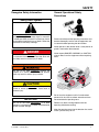
Recognize Safety Information
General Operational Safety
Precautions
Safety-Alert Symbol
The Safety-Alert Symbol identifies important safety
messages on equipment, safety signs, in manuals,
or elsewhere. When you see this symbol, be alert to
the possibility of personal injury or death. Follow the
instructions in the safety message.
Read and understand the operating instructions and
become thoroughly familiar with the equipment and
its controls before operating the dock leveler.
Never operate a dock leveler while a safety device or
guard is removed or disconnected.
The use of the word DANGER signifies the presence
of an extreme hazard or unsafe practice which will
most likely result in severe injury or death.
Never remove DANGER, WARNING, or CAUTION
signs or Decal’s on the equipment unless replacing
them.
on
The use of the word WARNING signifies the
presence of a serious hazard or unsafe practice
which may result in serious injury or death.
The use of the word CAUTION signifies possible
hazard or unsafe practice which could result in
personal injury.
IMPORTANT
The use of the word IMPORTANT is to draw
attention to a procedure that needs to be followed to
prevent machine damage.
Z
ing
rat
e
e
Op
era
Op
g
tin
ne
Zo
Do not start the equipment until all unauthorized
personnel in the area have been warned and have
moved outside the operating zone.
Remove any tools or foreign objects from the
operating zone before starting.
Keep the operating zone free of obstacles that could
cause a person to trip or fall.
4111-0030 — January 2014
1
SAFETY
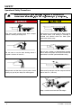
Operational Safety Precautions
¡
Stay clear of dock leveling device when transport
vehicle is entering or leaving area.
¢
£
¤
¢
Chock/restrain all transport vehicles. Never remove
the wheel chocks until loading or unloading is
finished and vehicles driver has been given
permission to drive away.
Do not move or use the dock leveling device if
anyone is under or in front of it.
Do not use a broken or damaged dock leveling
device. Make sure proper service and maintenance
procedures have been performed before using.
Keep hands and feet clear of pinch points. Avoid
putting any part of your body near moving parts.
Make sure lip overlaps onto the transport vehicles
bed at least 4 in. (102 mm).
Keep a safe distance from both side edges.
2
4111-0030 — January 2014
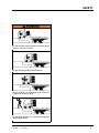
SAFETY
Do not use dock leveling device if transport vehicle
carrier is too high or too low.
Do not overload the dock leveling device.
Do not operate any equipment while under the
influence of alcohol or drugs.
Do not leave equipment or material unattended on
dock leveling device.
4111-0030 — January 2014
3
SAFETY
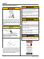
Maintenance Safety Precautions
ALWAYS disconnect electrical power source and
ground wire before welding on dock leveler.
DO NOT ground welding equipment to any hydraulic
or electrical components of the dock leveler. Always
ground to the dock leveler frame.
Failure to follow these instructions may result in
damage to dock leveler and/or serious personal
injury or death.
Hydraulic and electrical power must be OFF when
servicing the equipment. For maximum protection,
use an OSHA approved locking device to lock
out all power sources. Only the person servicing
the equipment should have the key to unlock the
device.
DO NOT grind or weld if hydraulic fluid or other
flammable liquid is present on the surface to be
ground or welded
DO NOT grind or weld if un contained hydraulic fluid
or other flammable liquid is present. Stray sparks
can ignite spills or leaks near the work area. Always
clean up the oil leaks and spills before proceeding
with grinding or welding.
Always keep a fire extinguisher of the proper type
nearby when grinding or welding.
Failure to follow these instructions may result in
serious personal injury or death.
Always post safety warnings and barricade
the work area at dock level and ground level
to prevent unauthorized use of the unit before
maintenance is complete.
ALWAYS stand clear of dock leveler lip when
working in front of the dock leveler. Failure to do this
may result in serious personal injury or death.
The maintenance prop must be in the upright “service”
position when working under the dock leveler. For
maximum protection, use an OSHA approved locking
device to lock the maintenance prop in the service
position. Only the person servicing the equipment
should have the key to unlock the device.
4
4111-0030 — January 2014
SAFETY
Safety Decal’s
Every 90 days (quarterly) inspect all safety labels and tags
to ensure they are on the dock leveler and are easily legible. If any are missing or require replacement, please call
1-800-643-5424 for replacements.
DANGER
CRUSH HAZARD
Maintenance prop must
support leveler behind bar.
Do not force maintenance
prop forward of bar to
support lip. Refer to
owner’s/user’s manual for
proper use. Failure to
comply will result in
death or serious injury.
1751-0727
1751-0727
1751-0730 (x2)
SAFETY INFORMATION
DANGER
Unsupported dock leveler
ramps can lower unexpectedly.
Before allowing vehicle to leave
the dock always:
!
Ensure that no equipment,
material or people are on the
dock leveler.
!
Return the dock leveler to its
stored position at dock level.
Failure to follow posted instructions will result in death or serious injury.
Operation
1. Read and follow all instructions and
warnings in the owner’s/user’s
manual.
2. Use of dock leveler restricted to
trained operators
3. Always chock trailer wheels or
engage truck restraint before
operating dock leveler or beginning to
load or unload.
4. Never use hands or equipment to
move the ramp or lip
5. Before activating dock leveler:
¥ Ensure trailer is backed in against
bumpers.
¥ Remove any end loads if required.
¥ Check trailer alignment to avoid lip
interference. If lip does not lower to
trailer bed, reposition vehicle.
6. Ensure that truck bed supports
extended lip or the leveler frame
supports the ramp before driving on
ramp.
7. Stay clear of hinges and front and
sides of moving dock leveler.
8. Never use damaged or
malfunctioning dock leveler. Report
problems immediately to supervisor.
Maintenance/Service
1. Read and follow all instructions,
warnings and maintenance schedules
in the owner’s/user’s manual.
2. Maintenance/Service of dock leveler
restricted to trained personnel.
3. Place barriers on the driveway and on
dock floor to indicate service work is
being performed.
4. DO NOT ENTER PIT unless dock
leveler is securely supported by
maintenance prop.
5. If electrically powered turn off and use
OSHA lockout/tagout procedures.
Call 262.255.1510 for replacement placards, warning labels, or owner’s/user’s manuals.
(decal placed in same position on both sides)
1751-0329 (x2)
DO NOT
FORK THIS SIDE
(decal placed in same position on both sides)
FORK
HERE
1751-0330 (x2)
(decal placed in same position on both sides)
! DANGER
CRUSH HAZARD
DO NOT REMOVE hydraulic cylinder until leveler is
safely supported by maintenance prop. Refer to
owner’s/user’s manual for proper maintenance
procedure. Failure to comply will result in death or
serious injury.
1751-0138
6<67(06,1&
1751-0729
DANGER
CRUSH HAZARD
Do not work under dock leveler unless this maintenance prop has been secured in the
upright position. See owner’s/user’s manual for proper procedures. Failure to comply
1751-0729
will result in death or serious injury.
C
C
DANGER
C
CRUSH HAZARD
C a
1751-0731
Rotate prop to maintenance
position. Open the pin latch
and insert through the
maintenance prop housing.
Close the pin latch to secure
prop. Use every time dock
leveler is serviced. Failure to
comply will result in death
or serious injury.
1751-0731
DANGER
1751-0726
CRUSH HAZARD
DO NOT ENTER PIT unless dock leveler is
safely supported by maintenance prop. Place
barriers on driveway and dock floor to indicate
service work being performed. Refer to
owner’s/user’s manual for proper maintenance
procedures. Failure to comply will result in death
or serious injury.
1751-0726
Note
This is a example of dock leveler safety decals. See manual for your specific model for
correct safety decal sheet or consult Tech Services
4111-0030 — January 2014
5
OWNER’S/USER’S RESPONSIBILITIES
¥
¦
§
¨
·
¦
¼
©
¬
²
¼
ª
¨
¸
º
¸
É
¬
©
º
µ
©
¹
¦
ª
Ä
¦
µ
¸
Ù
¦
Û
·
¨
¦
Ù
Õ
¦
¸
µ
¬
´
Ï
¨
¯
µ
©
·
¬
¸
´
°
ª
µ
³
´
±
¬
©
·
¬
µ
¬
¸
±
³
±
±
µ
±
©
¼
·
¸
©
¬
µ
ª
¸
·
ª
«
ª
¸
³
¬
·
¬
µ
¯
°
µ
©
³
¹
·
¬
©
¾
ª
¬
«
ª
³
°
¯
µ
ª
¯
±
·
¬
©
´
Á
·
¨
°
Á
º
¸
ª
°
¸
¬
²
ª
ª
¸
·
¦
Æ
¼
©
©
¸
µ
¬
¸
¬
»
µ
ª
¬
°
Â
´
±
©
©
¬
¯
¬
·
¹
ª
´
«
µ
¼
«
²
¸
·
À
©
¬
°
¸
ª
¬
¬
¸
©
²
³
ª
©
»
¨
¬
°
¹
³
·
©
Á
¸
©
À
ª
¬
À
°
¬
¼
²
µ
©
¬
ª
µ
´
°
À
°
ª
¬
ª
¯
²
µ
ª
³
®
¯
·
·
©
°
©
µ
²
¸
°
¿
º
¸
©
ª
©
©
¸
©
±
¼
²
¨
©
ª
¬
©
¹
¨
±
«
¼
¨
»
±
ª
ª
·
ª
·
¸
©
±
°
¬
·
¸
¨
±
©
³
¹
·
©
µ
©
¯
¯
¸
³
·
«
¬
´
¬
¬
¸
¬
·
°
ª
¬
©
¬
¸
°
µ
¹
º
µ
À
¯
©
±
©
²
¨
¸
¼
±
¹
³
·
¸
°
µ
ª
Å
¨
¸
¹
©
·
©
¬
©
°
µ
·
µ
ª
¯
¬
¸
©
°
²
«
³
±
¬
Â
µ
·
¸
½
µ
©
¾
²
¸
¨
©
²
´
¸
ª
ª
¬
·
ª
¯
¼
µ
¹
¹
ª
µ
¹
À
©
³
¨
·
ª
¸
ª
¸
¸
°
¹
¸
¬
²
°
©
°
¼
°
¨
´
¯
©
©
·
µ
µ
²
´
¾
·
¬
¾
²
¸
µ
¬
²
¬
¸
¬
¸
±
©
µ
´
²
¨
·
©
°
¹
©
µ
±
·
°
·
©
°
Â
©
·
±
¨
µ
¬
µ
±
¸
Á
°
°
®
ª
¹
¨
½
°
µ
½
³
¨
¸
µ
©
½
ª
¸
¸
·
µ
¬
°
¹
·
³
ª
¹
³
ª
·
³
°
¬
·
©
µ
«
µ
·
ª
µ
¸
·
µ
É
·
°
µ
ª
¬
É
·
¹
¬
·
²
³
³
ª
©
¸
©
¹
¸
¬
¨
À
²
³
¬
·
ª
¬
©
ª
¸
²
¹
©
¼
Ð
¯
¬
À
È
°
´
©
µ
À
·
µ
Â
ª
³
©
¹
³
¯
¬
¯
¸
©
¯
ª
ª
°
²
³
¬
©
Ë
¸
ª
³
¾
Ê
¯
©
©
°
¾
¨
¼
¬
µ
°
¼
ª
´
·
²
³
°
Ô
¦
©
¾
±
²
¼
ª
¹
¨
°
©
±
·
ª
¬
µ
²
¸
ª
µ
Õ
¸
³
°
µ
Õ
ª
©
©
²
°
¼
»
©
©
¿
¸
©
·
µ
±
°
©
¬
µ
±
¬
©
³
²
³
¬
©
¬
±
©
¥
²
·
ª
Ñ
¬
°
¹
ª
°
¸
µ
©
³
¨
´
¾
¬
¿
µ
ª
¯
¯
³
«
·
¨
µ
³
Õ
Õ
¬
±
ª
·
ª
¬
µ
µ
´
·
³
µ
ª
º
±
È
©
±
°
¸
µ
±
¸
©
¹
µ
¬
±
µ
¼
³
´
¸
½
¯
Â
µ
·
±
©
°
·
²
ª
²
©
ª
©
´
ª
µ
ª
«
¬
¹
¨
°
©
½
´
¸
½
ª
¬
Ê
¾
©
À
µ
²
¯
¬
±
©
²
¬
ª
»
¸
¸
¬
¸
±
§
À
ª
©
©
¸
¾
²
²
·
°
ª
©
²
¬
¬
¹
¨
¯
±
Â
µ
À
ª
·
Ò
²
µ
°
¸
À
¬
À
¸
¬
ª
±
À
¹
©
°
¯
±
ª
¬
¸
·
±
¨
©
ª
¬
©
¼
¨
±
ª
·
»
ª
°
©
¬
ª
¼
©
°
¸
³
¸
³
ª
«
ª
¼
²
³
²
½
´
¬
¯
¹
¼
°
³
©
ª
·
°
¬
«
´
©
·
¬
¨
µ
©
¬
±
´
©
¸
½
©
±
µ
¬
²
¬
´
¬
²
¦
²
µ
¼
¹
¸
°
¸
¬
µ
¬
©
µ
´
¬
°
·
¸
©
¬
²
©
²
¹
±
Á
©
¯
±
¨
©
±
µ
µ
·
µ
²
ª
ª
°
ª
¯
·
¸
©
·
ª
°
¹
ª
¦
°
¼
¸
¼
²
À
©
²
·
©
±
©
¬
¬
¹
¨
©
¯
©
·
©
·
À
¿
²
¯
¶
¸
©
©
²
ª
ª
·
³
¯
°
³
¸
°
°
±
·
¹
¼
¸
¯
¹
©
©
²
¼
¸
©
¯
©
°
¬
¾
·
³
³
µ
©
³
¬
µ
°
³
¸
©
©
²
ª
ª
¨
µ
¨
©
¬
©
¹
¬
°
À
²
©
©
¬
¸
·
µ
·
¸
·
µ
¨
¬
©
½
©
¾
¦
©
·
¯
¸
¯
©
©
¨
¬
©
©
º
·
ª
·
³
¯
©
¬
½
³
µ
Â
°
°
¼
·
¸
½
²
·
¸
Å
¹
©
¬
À
ª
©
³
µ
©
¼
¬
ª
©
°
°
©
¬
¸
¬
¸
¨
°
¸
¸
¼
À
·
¨
µ
¸
¬
¹
¬
À
¨
ª
ª
¸
»
°
©
·
¸
°
µ
ª
¬
·
³
·
·
¬
ª
Â
°
µ
³
ª
²
¸
¬
µ
¸
º
¸
¯
·
©
º
©
©
·
¬
²
·
¼
¸
¸
´
²
°
°
·
©
©
À
¸
µ
¸
©
¼
©
Â
·
³
¯
·
¹
¨
³
¸
¬
¬
µ
«
©
±
·
À
¼
µ
©
ª
¸
¯
²
À
¬
Â
´
¬
¯
©
³
¬
¸
³
´
±
¬
¹
©
ª
³
µ
µ
¸
©
À
¸
³
²
¸
¾
°
µ
¬
¬
ª
³
³
¸
·
º
±
¸
À
¯
ª
±
¯
¸
¬
©
±
³
¸
¬
¬
©
µ
À
¯
±
©
©
¨
µ
±
©
·
¬
¬
¬
´
±
ª
¦
¸
º
¸
±
µ
¸
¬
²
¨
µ
²
°
·
·
©
±
·
©
·
³
¸
Â
µ
´
²
¨
©
±
·
¯
Ä
±
²
¬
¼
¬
·
²
¯
´
°
¬
½
©
¸
¯
²
²
¹
©
µ
¾
µ
¹
±
½
°
°
¬
µ
ª
µ
©
©
µ
©
¹
²
À
°
¨
²
°
¬
©
©
À
±
À
¸
ª
À
·
·
©
·
ª
°
¸
À
¸
ª
¸
©
¬
ª
©
³
¨
¸
°
°
©
¬
©
µ
À
©
´
«
µ
¸
¬
µ
¸
¬
·
±
¯
¹
¨
¼
©
¸
¿
³
¯
·
µ
µ
¯
ª
¼
«
À
©
©
¹
µ
¬
ª
·
·
©
·
¬
«
·
¸
¸
¨
¼
°
¼
¼
©
¼
¸
µ
·
ª
½
ª
µ
¸
³
·
¯
±
±
ª
¸
¦
©
©
´
±
©
¬
¨
º
±
·
µ
µ
Ï
¬
©
·
¸
¦
¸
³
¾
¬
¸
À
À
°
©
ª
¸
°
³
½
²
¹
°
ª
µ
³
·
À
©
¬
·
¨
Ê
È
ª
ª
¬
³
¦
¸
±
±
µ
Â
©
µ
·
ª
·
³
·
©
³
©
«
©
ª
°
½
©
¬
°
µ
À
©
¹
²
©
±
©
º
¸
¬
¸
¯
©
¸
³
±
½
µ
©
µ
·
©
©
º
°
³
¨
©
¸
°
°
¸
±
¨
µ
©
µ
±
¸
´
¨
±
©
¬
¸
±
Å
½
º
¨
¯
©
¹
¯
©
·
©
¸
°
°
¯
·
¨
±
©
²
µ
©
±
º
Â
¯
²
¬
¼
·
µ
·
µ
¸
±
ª
¨
»
µ
¶
©
©
°
©
±
¦
ª
¸
¸
²
·
ª
¬
É
¼
²
²
·
µ
©
¹
µ
¬
ª
«
°
¨
ª
´
©
©
³
À
µ
©
ª
¬
¯
±
³
À
±
ª
±
¨
À
´
¬
ª
©
¸
ª
³
¬
²
µ
¸
»
²
¬
²
µ
¬
°
©
ª
¸
²
´
´
¼
·
¸
¬
¹
¼
¨
±
¸
µ
©
·
²
¼
¬
ª
²
·
¯
±
²
¸
¸
µ
ª
¸
±
¯
¼
©
¼
²
µ
³
¹
ª
°
¬
·
¼
«
´
µ
ª
·
ª
µ
À
¸
·
¨
¼
·
©
±
¸
©
¸
µ
·
µ
¨
Â
©
ª
Ý
ª
µ
²
©
¬
·
ª
¦
¯
µ
¬
¬
¨
¸
²
¼
ª
¹
±
¸
ª
¿
³
ª
µ
¨
²
©
Â
¸
ª
²
µ
°
²
©
±
©
°
©
©
ª
©
¸
½
·
²
·
µ
¸
µ
·
¨
¨
¬
·
¸
·
¨
ª
¼
·
±
¼
µ
·
º
¼
¹
¸
³
ª
±
¸
¬
¸
¸
¸
¬
±
©
ª
µ
À
¸
ª
±
·
À
©
±
¼
¸
¸
·
±
©
¸
½
©
°
¨
¸
©
¬
³
¬
±
À
¬
·
¬
¯
¼
°
±
Â
¸
·
¯
²
´
¾
·
¸
´
¬
¸
°
°
¬
¬
É
À
¨
µ
°
²
©
¸
³
³
¨
¸
©
µ
¦
±
¼
·
¸
³
©
¬
²
¸
©
¸
±
°
©
·
¸
©
Ñ
°
½
©
À
º
¸
±
µ
·
²
±
©
ª
©
·
²
±
µ
©
ª
À
¯
©
µ
¼
¯
·
¹
±
µ
È
¬
¬
¸
À
·
¨
¸
¬
²
µ
É
ª
µ
µ
¬
¸
Â
¿
©
ª
ª
¹
©
©
«
Ä
Å
¨
©
¸
·
©
¨
·
¨
¬
Ò
©
·
©
²
©
©
©
½
À
©
½
°
Ê
¸
¬
²
¯
À
¸
¬
·
ª
¼
°
À
¯
©
©
±
©
¬
·
·
¿
¯
¨
µ
·
°
¨
©
ª
À
¼
À
¯
¸
©
±
¬
¬
·
²
¬
¯
¦
¹
Æ
¸
©
½
³
¬
·
±
©
¯
Â
¼
º
©
©
µ
ª
¼
¯
¹
°
Â
©
©
ª
±
²
ª
¯
Â
¨
·
¯
¸
¸
·
½
µ
¬
°
µ
©
©
²
©
¸
ª
¬
²
¹
Â
¸
µ
¿
¬
·
¯
²
¸
°
µ
©
¬
°
¯
·
·
·
¨
µ
ª
©
¬
ª
²
¬
µ
©
°
¶
²
¸
©
¯
°
²
°
·
¼
©
¾
ª
©
·
°
½
¨
ª
©
©
·
¯
¬
¬
©
µ
°
³
¸
©
±
±
¾
°
¨
«
½
ª
©
ª
¯
±
·
»
µ
²
³
µ
¬
´
¸
ª
±
¼
«
©
¸
¬
ª
¸
·
´
»
©
©
µ
·
¾
¬
´
¨
©
¦
©
³
¯
±
©
»
¼
·
±
¹
±
¦
¸
¬
©
ª
Â
µ
Â
µ
³
·
¸
·
°
¸
¼
·
´
µ
¬
·
ª
¬
¸
¨
ª
µ
¸
©
½
²
²
©
²
©
¬
¬
¬
¸
¬
±
µ
º
¸
©
½
µ
©
²
¸
²
À
·
¬
¨
·
©
¼
¾
©
¹
©
¸
³
¯
¸
±
¸
ª
·
¬
µ
±
±
µ
¸
ª
°
ª
·
±
¬
¬
·
©
ª
µ
½
«
©
±
¸
³
¨
·
À
¼
°
¸
ª
¬
°
¬
ª
©
µ
¬
¨
¸
¬
©
°
µ
ª
·
¾
¸
·
©
©
¹
©
ª
±
©
·
©
À
©
±
©
¼
¨
¹
·
·
¬
²
©
°
±
µ
ª
ª
³
À
°
·
·
ª
¼
¸
µ
µ
µ
©
¸
¯
±
·
²
¬
¹
©
ª
·
ª
©
°
ª
¯
¹
¸
·
·
¬
¯
¸
µ
©
©
¿
¬
·
¨
°
©
©
¸
°
¬
¯
»
¼
©
²
¸
¨
¨
¼
«
À
¹
¯
Ò
µ
·
ª
³
À
µ
®
Ä
©
±
¸
°
ª
«
±
·
©
À
·
©
ª
²
·
¸
¯
©
¸
©
¯
³
¼
°
¶
¬
¼
µ
¬
·
©
¬
³
¬
ª
¸
¼
¼
¸
Ï
Ñ
´
·
ª
³
©
¿
¯
¸
¬
µ
·
¾
©
´
¯
°
µ
µ
¬
¸
¯
¹
º
©
³
µ
¯
½
°
Ê
¬
²
Â
¨
½
©
²
©
¸
¹
µ
³
²
¬
¸
µ
ª
¬
©
À
²
³
¿
º
6
¸
µ
µ
ª
¨
©
µ
©
¼
¼
¬
ª
²
±
²
À
·
±
µ
©
¹
¹
ª
¬
¾
¸
¸
¼
À
º
µ
°
¬
¯
±
»
µ
½
µ
µ
·
°
µ
ª
°
ª
¯
À
¥
±
²
¸
³
©
µ
©
¬
¬
±
°
ª
³
©
¸
²
¸
¨
¯
¨
ª
¦
²
©
ª
°
¯
¬
¨
©
©
¬
¾
·
¬
²
½
ª
¿
¬
É
«
º
¬
¬
±
ª
ª
«
ª
µ
¨
µ
¼
°
ª
¨
¸
µ
°
¸
·
·
·
¸
¬
²
©
Á
µ
¯
¸
¾
©
´
´
ª
·
Î
©
©
º
©
¨
·
±
¬
¯
©
¬
±
ª
»
¨
µ
²
°
©
µ
©
©
´
·
·
¬
¶
«
¬
³
µ
©
¬
µ
©
²
¸
µ
¸
µ
²
²
»
¨
·
©
·
µ
¬
Ö
¸
°
¸
¸
Â
¨
À
¹
À
°
²
·
¼
À
±
¯
³
©
·
°
´
·
¨
¬
À
¼
·
·
´
©
À
©
¸
µ
Â
Ï
¦
±
¼
·
Þ
©
³
©
®
¨
µ
ª
²
¹
¬
·
¬
©
¸
¹
©
´
¨
ª
ª
²
À
©
¬
¨
¸
¸
³
¬
°
¬
ª
²
ª
¸
Ü
µ
¼
¬
¸
´
²
©
·
©
¸
½
¬
¹
·
©
¬
À
¼
©
¹
¯
¼
¸
¯
¸
Ú
ª
À
ª
°
±
Ð
²
¬
¨
ª
·
Â
±
¹
¯
ª
§
Ã
³
ª
³
¦
¦
´
±
©
©
©
°
¬
³
©
µ
©
µ
±
¨
²
¬
¬
±
©
ª
ª
«
¬
«
µ
À
·
¸
·
¬
¨
²
Ø
¦
À
³
«
ª
µ
¼
·
·
©
µ
©
¯
Í
¬
¸
¨
ª
¸
©
©
¸
°
³
·
°
©
·
µ
²
³
·
·
²
½
Æ
·
²
À
·
µ
¹
¸
¸
µ
¦
Ê
µ
·
³
°
ª
·
Æ
³
¬
¸
±
·
¾
¸
ª
©
³
©
¸
ª
¬
¬
µ
¨
±
¹
µ
ª
½
§
¬
©
³
¼
×
µ
±
·
¸
¬
Ê
°
°
¬
µ
¹
ª
³
¬
±
¨
ª
²
©
¯
©
©
¬
¯
¸
©
¯
µ
¾
©
²
·
²
¦
±
µ
·
©
±
°
©
ª
½
¸
¼
ª
¨
¬
·
¼
¨
±
¬
·
³
²
ª
°
ª
¯
°
ª
À
¸
¸
©
µ
¨
µ
Ô
À
µ
²
°
¼
·
²
¸
µ
©
¸
Â
²
¨
¯
À
²
°
¿
¼
¬
¬
°
·
¬
·
¬
¬
°
°
«
É
¸
¯
¸
°
¸
¸
®
ª
¬
¯
°
©
¼
ª
°
Á
ª
¸
µ
©
©
¹
¸
·
©
°
²
°
¯
·
¦
µ
µ
¨
¬
·
¬
µ
©
§
¬
¸
³
º
°
É
µ
¬
¸
µ
°
¨
«
±
Ì
Ó
·
¸
¯
ª
©
ª
·
Ç
©
¨
·
·
¯
µ
¬
©
´
±
¼
ª
±
¸
¸
²
¬
µ
°
¬
´
¸
²
¬
²
ª
³
¸
»
¬
°
Â
¸
¼
¹
ª
©
°
·
°
Â
©
µ
º
¿
±
©
¯
µ
¸
²
¼
À
½
©
©
¬
°
·
©
¾
µ
³
·
µ
ª
°
¬
µ
²
À
µ
¼
·
µ
ª
ª
¬
°
·
¸
¾
¬
©
·
¬
·
½
ª
³
µ
ª
ª
¬
¬
À
°
©
µ
²
¬
©
·
¸
¬
±
¹
ª
¸
·
³
ª
·
ª
¬
±
°
Â
¼
ª
©
¯
°
°
©
¸
¬
´
·
©
©
¿
¯
µ
©
À
©
¬
·
°
¦
4111-0030 — January 2014
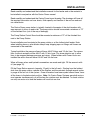
INTRODUCTION
THEORY
General Information
The Centra Power System eliminates individual
hydraulic pumps located on each leveler. The
Centra Power pump station will run multiple
dock levelers and or vehicle restraints. When a
dock leveler or vehicle restraint are operated,
one electrical signal is sent to the pump station
activating the hydraulic power unit. A signal
is also sent to the Centra Power valve at the
door position being operated. The combination
of these two signals allow the dock leveler or
restraint to operate. The Centra Power pump
station allows more than one leveler or vehicle
Congratulations on your choice of a Poweramp
restraint to operate at the same time.
dock leveler. This manual covers the Centra Power
hydraulic system.
Designed by Poweramp to be a marvel of simplicity
and efficiency, your Centra Power hydraulic system
properly installed, will provide many years of troublefree performance with an absolute minimum of
maintenance. Its revolutionary hydraulic system
efficiently controls and operates every function. To
obtain maximum performance and longest possible
use, a simple program of preventive maintenance is
recommended.
The Centra Power System comes equipped with an
electrical control panel, which allows push button
operation of the dock leveler functions. Each dock
leveler and control panel has been factory prewired
and tested to ensure satisfactory operation.
To illustrate which connections are to be made
in the field at installation, electrical drawings are
included with each order or by contacting Poweramp
Technical Services.
Once again, thank you and congratulations on your
purchase of a Poweramp Centra Power System.
4111-0030 — January 2014
7
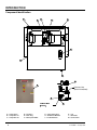
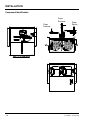
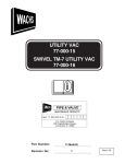
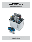
INTRODUCTION
Component Identification
ã
ä
è
å
æ
ç
ê
é
á
à
Pressure Line
(Black Valve,Steel)
ß
ë
ì
í
î
ï
ð
ñ
ò
ð
ì
â
ó
A — Pump Station
B — Pump Motor #1
C — Pump Motor #2
8
D — Site Glass
E — Drain Plug
F — Main System Relief
ô
ï
õ
ö
ö
÷
G — Pump Station Door
H — Distribution Manifold
J — Leveler Manifold
K — Coil
L — Ball Valves
M —Control Panel
4111-0030 — January 2014
INSTALLATION
Read carefully and understand the installation manual for the leveler and or the restraint to
be installed in conjunction with the Centra Power manual.
Read carefully and understand the Centra Power layout drawing. The drawings will have all
the required information on hose charts, fluid capacity and location of the mid run and end
run valve blocks.
The Centra Power pump station is typically located in the center of the dock levelers with
even amount of doors on each side. The pump station should be mounted a minimum of 72”
off the finished floor (out of the way of damage).
The Pump Station Control Box should be mounted a minimum of 72” off the finished floor
next to the Pump Station.
Hose installation can be started at the pump station or at the furthest dock leveler. Note:
when installing hose or valve blocks always keep shipping caps on fittings until hoses are
connected to the manifolds.
Typical installation the pressure lines will have #8 JIC fittings and 1/2 dia. lines. The returns
lines if without restraints will be #8 JIC with 1/2 dia. hose. Pay close attention not to allow
lines to be swapped between pressure and return. When levelers with Power Hooks are
installed the return lines will have #10 JIC and 3/4 dia hose.
When all hoses valves and hydraulic connections are made and tight. Fill the reservoir with
oil (see page 15).
Fill the Pump Station reservoir (capacity 12 gals) to the full mark. Starting from the furthest
dock from the pump station, operate all the levelers and the restraints through several cycles
to purge all the air out of the system. Once all levelers have been cycled several times, have
all the levers in the below dock position. Note: On Centra Power Systems were both motors
must operate simultaneously run all the time the rotation must be checked. To check rotation
run only one motor at a time the levelers will work but run slow.
4111-0030 — January 2014
9
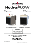
INSTALLATION
Component Identification
Pump
Pressure
Pump
Pressure
10
Pump
Return
4111-0030 — January 2014
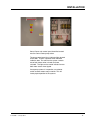
INSTALLATION
Centra Power main control panel should be located
near the Centra Power pump station.
The pump control panel has 2 indicator lights located
on the door. There is 3 position switch mounted
inside the door. The switch on the system controls
one or both motors when a leveler has been
activated. The lights on the control indicate if one or
both motor starters have tripped.
If one pump systems is in operation, use selector
switch to rotate motors every 6 months. This will
insure proper operation of the systems.
4111-0030 — January 2014
11
INSTALLATION
IMPORTANT
DO NOT grind or weld if hydraulic fluid or other
flammable liquid is present on the surface to be
ground or welded
DO NOT connect the dock leveler electrical wiring
and ground connections until all welding has been
completed.
DO NOT grind or weld if un contained hydraulic fluid
or other flammable liquid is present. Stray sparks
can ignite spills or leaks near the work area. Always
clean up the oil leaks and spills before proceeding
with grinding or welding.
DO NOT ground welding equipment to any
hydraulic or electrical components of the dock
leveler. Always ground welding equipment to the
dock leveler frame, NEVER to the platform.
Always keep a fire extinguisher of the proper type
nearby when grinding or welding.
Failure to follow these instructions may damage the
motor, hoist cylinder, wiring, and/or control panel.
Failure to follow these instructions may result in
serious personal injury or death.
12
4111-0030 — January 2014
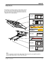
MAINTENANCE
Service Dock Leveler Safely
ø
ù
ú
û
ü
ý
þ
ÿ
ý
û
ý
ÿ
ù
û
þ
ÿ
ü
ÿ
ù
þ
When service under the dock leveler is required,
always lock all electrical disconnects in the OFF
position after raising the platform and engaging the
maintenance prop. Failure to do this may result in
serious personal injury or death.
Always stand clear of the dock leveler lip when
working in front of the dock leveler.
The maintenance prop MUST be in the service
position when working under the dock leveler.
For maximum protection, use an OSHA approved
locking device to lock the maintenance prop in
the service position. Only the person servicing
the equipment should have the key to unlock the
maintenance prop.
Unless the dock leveler is equipped with a tethered
remote, two people are required to engage the
maintenance prop: one person to operate the unit,
the other person to engage the maintenance prop.
Failure to follow these instructions may result in
serious personal injury or death.
ÿ
ü
ÿ
ù
ý
þ
ÿ
û
ÿ
Always post safety warnings and barricade the
work area at dock level and ground level to prevent
unauthorized use of the dock leveler before
maintenance is complete. Failure to do this may
result in serious personal injury or death.
Whenever maintenance is to be performed under
the dock leveler platform, support the platform with
maintenance prop (A). Position the maintenance
prop behind front header plate (D) while staying clear
of the lip. The lip will fold down after the platform
has rested on the maintenance prop. Lock the
maintenance prop in the service (upright) position
using an OSHA approved lockout device* (C) and
tagout device* (B).
Whenever servicing the dock leveler, lock the
electrical power disconnect in the OFF position. Use
only an OSHA approved lockout device* (C) and
tagout device (B).
Only the person servicing the equipment should
have the capability to remove the lockout devices.
The tagout devices* must inform that repairs are in
process and clearly state who is responsible for the
lockout condition.
* Refer to OSHA regulation 1910.146
* Refer to OSHA regulation 1910.147.
4111-0030 — January 2014
13
MAINTENANCE
This page in intentional left blank
14
4111-0030 — January 2014
MAINTENANCE
Periodic Maintenance
Regular maintenance must be performed on a weekly
and quarterly schedule. For proper lube points see
owners manual for the equipment to be maintained.
Weekly Maintenance
• Operate the dock leveler through the complete
operating cycle to maintain lubrication.
NOTE: To thoroughly inspect the platform hinge
area, put the platform in the full below-dock
position.
• Inspect the platform hinge and the lip hinge areas.
The hinge areas must be kept free of dirt and
debris. Build-up of foreign material in the hinge
areas will cause abnormal operation.
Quarterly Maintenance
IMPORTANT
Failure to properly lubricate the dock leveler will
cause abnormal operation of the leveler.
• Fluid level must be checked periodically.
1. Pit levelers with or without restraints. levelers
must be in the below dock/cross-traffic position
level must read in the sight glass area.
2. VS Levelers with or without restraints must be
in the stored positon leveler should level must
be in site glass area.
3. Add hydraulic fluid if necessary. Use only
recommended fluid.
IMPORTANT
A low fluid level or the use of hydraulic fluids not
equivalent to the fluid types recommended, will
cause abnormal operation of the leveler and WILL
void warranty.
To ensure normal operation of the dock leveler,
use only aircraft hydraulic fluid designed to meet
or exceed military specification MIL-H-5606-G. It is
recommended that the following hydraulic fluids be
used:
• Ultra VIS HVI 15
• Aero Shell Fluid 4 or Fluid 41
• Mobile Aero HFA Mil-HS606A or Aero HF
• Texaco Aircraft Hydraulic Oil 15 or 5606
• Exxon Univis J13
IMPORTANT
Use of fluids that do not have equivalent
specifications to those in the following list will result
in abnormal operation of the dock leveler and
voiding of warranty.
4111-0030 — January 2014
These fluid brands can be mixed together. Mixing
with fluids that do not meet or exceed MIL-H-5606-G
may damage the equipment and WILL void warranty.
Use of hydraulic fluids with equivalent specifications
to those listed here are acceptable.
15
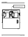
ADJUSTMENTS
Pressure relief:
Main pressure relief is pre set from the factory Call
Tech Services before adjustments are made.
16
4111-0030 — January 2014
TROUBLESHOOTING
Troubleshooting
When service under the dock leveler is required,
always lock all electrical disconnects in the OFF
position after raising the platform and engaging the
maintenance prop. Failure to do this may result in
serious personal injury or death.
Always stand clear of the dock leveler lip when
working in front of the dock leveler.
Always post safety warnings and barricade the
work area at dock level and ground level to prevent
unauthorized use of the dock leveler before
maintenance is complete. Failure to do this may
result in serious personal injury or death.
Unless the dock leveler is equipped with a tethered
remote, two people are required to engage the
maintenance prop: one person to operate the unit,
the other person to engage the maintenance prop.
The maintenance prop MUST be in the service
position when working under the dock leveler.
For maximum protection, use an OSHA approved
locking device to lock the maintenance prop in
the service position. Only the person servicing
the equipment should have the key to unlock the
maintenance prop.
Failure to follow these instructions may result in
serious personal injury or death.
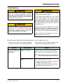
Before performing the detailed troubleshooting procedures, check the following items first:
• Check all fuses inside the control panel(s). Replace
any blown fuse(s) with a fuse of equal specification.
Symptom
• Make sure the correct voltages are present at the
proper locations inside the control panel(s).
Possible Cause
Platform or restraint will Motor overload device
not operate. Motor does tripped or fuse blown.
not energize.
Solution
Reset 3phase overload relay (Located next to pump
station) or replace fuse. Reset 120 volt overload
relay or replace fuse in the individual control box’s.
NOTE: When replacing fuse(s), the new fuse must
have the same specification as the old fuse.
No voltage at over loads or
relays
Check voltage at starter or relay coil.
•
•
4111-0030 — January 2014
If voltage is present and starter or relay does not
energize, replace starter or relay.
If voltage is not present, check all components in
series with the starter or relay coil.
17
TROUBLESHOOTING
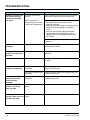
Symptom
Platform or restraint will
not operate correctly,
motor hums, but does
not rotate.
Possible Cause
Solution
No voltage is present on
one line.
Check for blown fuses at branch circuit disconnect.
Replace fuse. Determine cause of blown fuse.
NOTE: A motor that is
missing voltage on one line
is said to be single-phased.
Check motor starter as follows:
1. Disconnect wires at load side of starter.
2. Energize the starter.
3. Measure line-to-line voltage at line side of starter.
4. Measure line-to-line voltage at load side of
starter.
5. Line-side and load-side voltages should be
approximately the same. Replace starter if
voltage values are considerably different from
one another.
Check all wiring to motor for high resistance or no
connection.
Platform does not rise to Low hydraulic fluid.
full height.
Add fluid as needed. See Periodic Maintenance in
the Maintenance section.
Motor rotates but
platform or restraint not
operating.
Phase reversed.
Reverse any two legs at the branch circuit
disconnect.
Platform rises slowly
Pressure relief set too low.
Consult the factory, contact tech before adjustments
are made.
Only one Platform or
restraint not operating.
Bad coil on Centra Power
valve block.
The coil will magnetized when energized (Pump
Motor must be running)
Bad Valve on Centra Power Remove and clean spool valve or replace with new
valve block.
or good working valve.
Platform or restraint
operates when other
units have been
activated.
Platform does not raise.
Pump runs, Coil and
valve are good.
Bad Valve on Centra Power Remove and clean spool valve or replace with new
valve block.
or good working valve.
See Leveler specific
manual.
Restraint does not
See restraint specific
operate. Pump runs, Coil manual.
and valve are good.
18
4111-0030 — January 2014
PARTS
Centra Power Control Panel
4111-0030 — January 2014
19
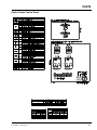
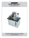
PARTS
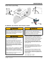
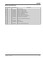
Mid Run Valve W/O Hook
9
:
:
>
;
;
@
7
6
=
<
Pressure Line
8
?
Return Line
Coil De-Energized when lever or restraint is Engaged not in use.
Coil Energized when lever or restraint is Engaged.
IF used as run is end cap will be required
!
"
20
#
$
%
&
%
"
'
(
)
&
#
&
)
&
!
*
&
!
$
+
)
,
-
.
/
&
!
0
1
&
,
'
+
)
)
$
,
2
"
!
3
+
4
$
,
2
"
!
%
&
!
*
5
4111-0030 — January 2014
PARTS
Mid Run Valve W/O Hook
Item
Quantity
Part Number
A
B
C
D
E
F
G
H
I
1
1
1
1
2
1
1
2
1
8581-0005
8581-0001
8581-0002
9301-0246
0521-0108
9301-0116
9301-0054
9904-0078
Valve Manifold
Valve - Cartridge - 3 way
Ball Valve - Bronze, Return
Ball Valve - Steel, Pressure
Fitting - #8ORB Male / 3/8 NPT
Fitting - #8 JICM Plug
Fitting - Elbow 90 male #8 JIC
Fitting - Branch - Tee - Male #8 JIC
Hyd Hose -3/8 x 35.00 Hose
J
1
8583-0021
Centra Power Mid Run W/O Restraint
K
L
1
8581-0004
Delta Coil
1
4301-0004
Cable Assembly
M
2
0521-0021
Fitting - #8 End Cap (Not Shown)
4111-0030 — January 2014
Description
21
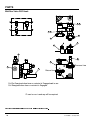
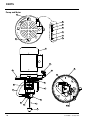
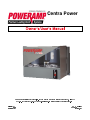
PARTS
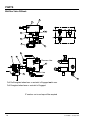
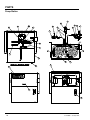
Mid Run Valve W/Hook
E
N
J
K
H
G
D
F
B
C
A
Pressure Line
L
M
Return Line
I
Coil De-Energized when lever or restraint is Engaged not in use.
Coil Energized when lever or restraint is Engaged.
IF used as run is end cap will be required
22
4111-0030 — January 2014
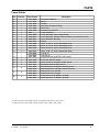
PARTS
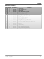
Mid Run Valve W/Hook
Item
Quantity
Part Number
A
B
C
D
E
F
G
H
I
J
K
L
1
1
1
1
1
1
1
1
1
1
1
1
8581-0005
9301-0104
9301-0098
8581-0072
9301-0246
8581-0092
9301-0054
8581-0002
9301-0247
9301-0112
9301-0116
Valve Manifold
Valve - Cartridge - 3 way
Fitting #4 SAE
Fitting - Male Branch Tee #10 JIC
Ball Valve - Bronze 1/2 NPT
Fitting - 3/8 NPT x #8 Male
Valve - Flow Control - 5 GPM
Fitting - Branch - Tee - Male #8 JIC
Ball Valve - Steel
Fitting - 1/2 NPT #8 ORB Male
Fitting - #8 ORB x #8 JIC
Fitting - Elbow 90 deg #8 ORB x #8 JIC
M
1
8583-0031
Centra Power Mid Run With Restraint & Flow Limiter
N
O
1
8581-0004
Delta Coil
1
4301-0004
Cable Assembly
P
Q
1
1
0521-0021
0521-0106
Fitting - #8 End Cap (Not Shown)
Fitting - #10 End Cap (Not Shown)
4111-0030 — January 2014
Description
23
PARTS
Pump Station
Z
_
b
c
^
e[
_
[
X
a
R
U
Y
Z
]
S
\
V
`
Q
P
W
d
O
T
24
4111-0030 — January 2014
PARTS
Pump Station
1
2
Item
Quantity
Part Number
Description
A
B
C
D
E
F
G
H
I
J
K
L
M
N
O
1
1
1
1
1
1
2
1
1
1
2
1
1
1
1
P
1
Q
1
9394-0003
1751-0072
9301-0048
9301-0049
9571-0005
9301-0199
9301-____ 1
8581-0037
8583-0037
8585-0001
9301-0027
9904-0090
9904-0082
9904-0106
9904-0107
9393-0008
9393-0009
0521-0032
Enclosure Weldment
Decal
Handle
Site Glass (Includes O-Ring)
Drain Plug
Breather Cap 3/8” NPT
Pump Assembly
Valve Assembly, Centra Power Relief
Valve Assembly, Includes Relief and Hose (Includes Items H &O)
Valve Assembly, Blending
0-Ring
Hose, 17.50” Lg. #8 JIC Swivel Both Ends
Hose, 21.75” Lg. #8 JIC Swivel Both Ends
Hose, 28.00” Lg. #8 JIC Swivel Both Ends
Hose, 9.00” Lg. #8 JIC Swivel Both Ends
Tee #8 Jic
Tee #10 Jic
Male Swivel Nut 3/8 NPTM x JICF Swivel
R
S
T
1
2
2
U
2
V
2
W
2
8581-0002
9904-0044
0521-0015
0521-0032
9301-0193
8581-0001
8581-0072
0521-0015
9301-0194
Valve, Ball 3/8 NPT (Steel)
Hose, 24.00” Lg. #8 JICM / #8JICF Swivel
Male Connector 3/8 NPTx #8 JIC
Male Swivel Nut 3/8 NPTM x #8 JICF Swivel
Male Swivel Nut 1/2 NPTM x #10 JICF Swivel
Bronze Ball Valve 3/8 NPT
Bronze Ball Valve 1/2 NPT
Male Connector 3/8 NPTM x #8 JICM
Male Connector 1/2 NPTM x 10 JICM
Provide dock leveler serial number and type of installation when calling or faxing orders.
Provide dock leveler serial number, voltage, and phase when calling or faxing orders.
4111-0030 — January 2014
25
PARTS
Pump and Motor
g
j
l
h
i
k
m
n
o
p
|
t
f
f
y
u
s
v
x
w
r
f
z
{
q
26
4111-0030 — January 2014
PARTS
Pump and Motor
Item
A
B
C
D
E
F
G
H
I
J
K
L
M
N
O
P
Q
R
S
T
U
V
W
Quantity
Part Number
1
1
1
3411-0043
3411-0045
-
Motor 460 3 PH 1-1/2 hp
Motor 460 3 PH 3 hp
Drive Plate
Description
1
1
1
1
1
3
1
1
1
1
1
1
1
1
4
2
2
1
1
1
1
1
9301-0027
9302-0065
9301-0204
9301-0205
9904-0001
9301-0007
9301-0206
9301-0009
0521-0014
9301-0024
9302-0009
9303-0003
9301-0014
9301-0016
2101-0016
9301-0003
9301-0004
9301-0069
9301-0106
9571-0006
9301-0145
0521-0016
O-Ring
Coupler (Love Joy)
Pump 5 GPM
Pump 4 GPM
Hose Assy - 3/8 17.500 Lg. #6 SAE to #8 JIC
Fitting Elbow 90 Deg 3/8 NPTM X 3/8
Fitting 3/8 NPT x 4-1/2
Strainer
Ball - Steel
Guide - Ball Check
Spring - Pressure Relief
Screw Adjusting
Washer - Nylon
Acorn Nut - High Crown
Hex Head Capscrew 5/16 UNC x 3-1/2 Lg.
Washer - Aluminum
Socket Head Cap Screw 3/8 UNC x 1-3/4 Lg.
Fitting Pipe Nipple 1/8 Npt x 5 Lg.
Fitting, Plug Hollow Hex, Str Thread
Fitting, 1/4 NPTM
Fitting, Elbow, 90 Degree, Swivel Nut
Fitting, Elbow, 90 Degree
* Provide dock leveler serial number and size of platform when calling or faxing orders.
4111-0030 — January 2014
27
NOTES
This page intentionally left blank
28
4111-0030 — January 2014
MISCELLANEOUS
Customer Information
}
NOTE: Refer to illustration for left/right orientation of
dock leveler.
The model/serial number decal (A) is located
on the right platform joist near the front (lip)
of dock leveler.
Dock Leveler Information
Model ___________________________________
Serial No. ________________________________
Systems, Inc., Job No. ______________________
When you receive your dock leveler, write down the
dock leveler model and serial number in the form
provided. This will help ensure safe keeping of the
numbers in the event the model/serial number decal
(A) becomes lost or damaged.
Original Owner Information
Name ___________________________________
Also, write down Systems, Inc.’s job number, the
company that installed the dock leveler, and the
original owner’s name. This will all help to identify the
specific dock leveler if more information is required.
Address _________________________________
When ordering, use part numbers and description
to help identify the item ordered. Do not use “item”
numbers. These are only for locating the position of
the parts. Always give dock leveler MODEL NUMBER
and/or SERIAL NUMBER.
Name ___________________________________
For service, call or contact:
Date of Installation ________________________
________________________________
Installer Information
Address _________________________________
_________________________________
Systems, Inc.
P.O. Box 309
Germantown, WI 53022
Phone: (800) 643-5424
Fax: (262) 255-5917
4111-0030 — January 2014
29
~
~
§
³
ª
ª
®
~
·
~
ª
~
³
°
ª
ª
µ
©
²
~
©
£
¥
¨
£
©
£
¤
¦
£
~
~
~
¤
£
£
£
¬
~
~
~
²
²
«
ª
ª
³
~
±
±
µ
³
±
«
~
ª
®
ª
ª
³
´
µ
~
µ
~
~
®
~
~
²
«
±
±
®
©
±
ª
±
±
~
³
«
~
®
©
³
~
¶
«
ª
±
°
µ
©
«
~
µ
µ
±
²
±
±
µ
ª
¶
±
°
~
¸
©
µ
³
²
«
°
©
²
ª
±
~
~
~
ª
²
~
ª
ª
~
ª
¶
©
~
µ
±
«
³
³
«
ª
©
ª
ª
±
µ
~
²
~
²
²
ª
ª
«
®
²
²
±
«
±
®
£
~
±
²
¶
®
ª
±
²
±
°
«
µ
±
¦
«
±
ª
¯
²
³
¢
±
¶
ª
°
~
ª
³
µ
«
¡
¥
~
§
¯
²
±
ª
ª
©
®
±
±
ª
ª
£
²
¢
¡
£
~
²
²
²
~
µ
µ
~
²
ª
ª
±