1
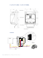
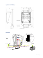
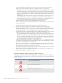
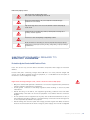
P_MOVOC
MOTOR VOLTAGE CONTROLLER
DEVICE
User Manual
Conformities
Declaration of Conformity
For PMC components there are declarations of conformity
available. These declarations confirm that the components
are designed according to valid EC directives. If required,
you can ask your sales representative for these declarations.
Low-Voltage Directive
The PMC products of a drive system mentioned in this
documentation comply with the requirements of the EC
Directive (see page 10).
Safety Instruction
Please read before the initial startup. See page 13.
2 | P_MOVOC Motor Voltage Controller Device
EMC Directive
The PMC products of a drive system mentioned in this
documentation comply with the requirements of the EC
Directive (see page 10).
CE Label
P_MOVOC
MOTOR VOLTAGE CONTROLLER
DEVICE
User Manual
Application Manual and Technical Specification
Rel.1
17-01-2014
GENERAL
The P-MOVOC device is supplied as a necessary complement of the range of advanced
frameless PM series TK motors when a constant power range in excess of 3:1, and up and
beyond 1:10, is planned for the application.
The special design and manufacturing technology of high speed TK motors allows a very
wide constant power, flux controlled operating range which can exceed the ratio 10:1. This
means that the motor back EMF is approximately equal to the drive maximum voltage (typically very close to the supply voltage) at the motor knee speed, i.e. at the lowest speed of
the constant power range. In normal operation, at higher speeds the drive feeds the motor,
which is designed to display a calibrated, critical amount of impedance, with just the right
amount of Id to keep the motor voltage constant throughout the constant power range. This
means that at the highest permissible speed the motor back EMF is higher than the supply
voltage, intrinsically the back EMF is about equal to the supply voltage times the constant
power range.
As a consequence, without a voltage controller device, if the drive were to stop supplying Id
to the motor when operating in flux control mode, a high voltage would be fed to the motor
terminals. The vantage controller is thus added to the motor circuit to prevent any such occurrence.
The voltage controlled device is connected between drive and motor, generally and preferably near the drive. If, for any reason, the drive were to stop supplying Id to the motor while
operating at high speed, the voltage controller would detect the voltage rise and trigger a
crowbar short circuiting all motor terminals so that the voltage across the motor is nullified
and the current in the device is the short circuit current of the motor. In turn, the short circuit current of high speed motors is very close to the nominal motor current.
The motor would then idle down with high current but relatively little braking power.
The motor voltage controller operates with or without power supply and only clears the motor
short when the motor is completely stopped.
Additional ground fault protection
The motor voltage controller operates whenever the drive is disabled or loses control at high
speed. This can be considered a repetitive non fault occurrence, caused by debugging, sudden loss of power, or other safety trips in the system.
The motor voltage controller also provides an additional protection for the unlikely occurrence of a breakdown of the motor or of the cable system at high speed. If a motor cable
or winding should break open at high speed, and the motor side open terminal would then
accidentally fail short to ground, e.g. because of extensive sparking or flashover, then the
remaining two terminals would experience a high voltage with respect to ground. In this
event, the motor voltage controller would trip a crowbar to ground again nullifying the voltage
across the motor terminals and in respect to ground.
Mechanical Data
Ambient temperature
- 20˚C - 60 ˚C
Protection IP
54
Vibration level
5 g. max all directions
Dimensions
Max power conductor section
(see drawing Fig)
16 sq mm (P_MOVOC 40/80)
4 | P_MOVOC Motor Voltage Controller Device
70 sq mm (P_MOVOC 200)
Control interface
The voltage control device operates safely independently from the control interface. A control interface is provided for monitoring and coordination with the drive.
The control interface requires a 24 Vdc supply and is fully insulated.
Control interface connector signal specification
Pin
Function
Typ spec
Remarks
1
Firing input
Digital input, 24V
Forced crowbar firing. For testing purpose according to
applicable safety protocols.*
2, 3
MOVOC Ready
Relays contacts, NO,
50 mA, 24V max
Closed when MOVOC is ready to operate.
Opens:
1.For two minutes after MOVOC power-on;
2.For two minutes after MOVOC firing;
3. In case of MOVOC overtemperature;
4. If an internal fault is detected, i.e. if a test firing signal is
not followed by the closing of operation relays 4,5
This output can be used to perform MOVOC test prior to
enabling high speed drive operation according to
applicable safety protocols.
4, 5
MOVOC Firing
Relays contacts, NO,
50 mA, 24V max
6
Aux +
Power supply input,
18-30 V, 50 mA
7
Aux -
Closed and latched within 10 ms from MOVOC firing.
Clears after 2 min from each firing.
Electrical characteristics, power terminals including ground protection:
P_MOVOC 40A
Crowbar maximum
current
Rated current
P_MOVOC 80A
60 [A]
40 [A]
Crowbar maximum
current
Rated current
P_MOVOC 200A
120 [A]
80 [A]
Crowbar maximum
current
250 [A]
Rated current
200 [A]
Thermal rating,
crowbar current 20A
> 120 [s]
Thermal rating,
crowbar current 60A
115 [s]
Thermal rating,
crowbar current 150A
> 120 [s]
Thermal rating,
crowbar current 30A
110 [s]
Thermal rating,
crowbar current 70A
75 [s]
Thermal rating,
crowbar current 175A
60 [s]
Thermal rating,
crowbar current 40A
90 [s]
Thermal rating,
crowbar current 80A
45 [s]
Thermal rating,
crowbar current 200A
25 [s]
Thermal rating,
crowbar current 50A
40 [s]
Thermal rating,
crowbar current 100A
20 [s]
Thermal rating,
crowbar current 225A
10 [s]
Thermal rating,
crowbar current 60A
15 [s]
Thermal rating,
crowbar current 120A
10 [s]
Thermal rating,
crowbar current 250A
4 [s]
Crowbar firing voltage (min - max)
790Vdc - 820Vdc
Crowbar firing voltage, equivalent motor terminal voltage (min - max)
560Vac - 580Vac
Recovery time after the first intervention:
P_MOVOC 40A
Recovery time, crowbar
current 40A for t >120 [s]
P_MOVOC 80A
15 [min]
Recovery time, crowbar
current 80A for t = 56 [s]
P_MOVOC 200A
6 [min]
Recovery time, crowbar
current 200A for t = 25 [s]
3 [min]
General | 5
P_MOVOC 40A / P_MOVOC 80A
Connections
CONTROL INTERFACE CONNECTOR
1
Test Fire Input
2
DCLink Ready - Pulse Enabling
3
DCLink Ready - Enabling Voltage
4
MOVOC Firing
5
DRIVE
U V W
MOVOC Firing
6
PE
W
V
U
Supply +24V
7
Supply 0V
Use Phoenix Female Socket p/n 1952319
MOTOR
PE
W
PE
V
U
6 | P_MOVOC Motor Voltage Controller Device
P_MOVOC 200A
CONTROL INTERFACE CONNECTOR
1
Test Fire Input
2
DCLink Ready - Pulse Enabling
3
DCLink Ready - Enabling Voltage
4
MOVOC Firing
5
DRIVE
U V W
MOVOC Firing
6
PE
W
V
U
Supply +24V
7
Supply 0V
Use Phoenix Female Socket p/n 1952319
MOTOR
PE
W
PE
V
U
Connections
CONTROL INTERFACE CONNECTOR
1
Test Fire Input
2
DRIVE
U
3
V
5
DCLink Ready - Pulse Enabling
DCLink Ready - Enabling Voltage
4
MOVOC Firing
MOVOC Firing
6
W
PE
Supply +24V
7
Supply 0V
Use Phoenix Female Socket p/n 1952319
MOTOR
U V W PE
W
V
U
PE
General | 7
Operating environment requirements
TEMPERATURE
MOVOC function is guaranteed in a range of
temperatures from
-20°C to 60° ambient.
Diagnostic can check the heatsink temperature and report a dangerous condition.
RELATIVE HUMIDITY
MOVOC device maintains its correct functionality from 0% to 95% of relative humidity.
ELECTROMAGNETIC COMPATIBILITY
DIRECTIVE
This product accords to:
EMC DIRECTIVE 2004/108/CE
It satisfies the requirements of:
»» EN 61000-6-4
»» EN 61000-3-2
»» EN 61000-6-2
POWER ON INTEGRITY SELF TESTS
Software has only diagnostic purpose, the
safety is warranted by hardware circuit. If
the SCR driver can’t switch on the SCR,
it can switch on itself when reaching the
1100Vdc threshold set by the zener branch.
SIL CAPABILITY
Referring to CEI EN 62061 and comparing
PFH (coming from fault tree analysis), SFF
and Hardware Fault Tolerance value P_MOVOC reach a level of SIL3.
CATEGORY AND PERFORMANCE LEVEL
Referring to EN ISO 13849-1 P_MOVOC device is classified as a CAT.2 PL D device.
TESTING
Routine tests:
P_MOVOC device will be tested in the operating temperature range.
Refer to EMC Technical reports
LOW VOLTAGE DIRECTIVE
This product accords to:
LV DIRECTIVE 2006/95/CE
It satisfies the requirements of:
»» EN 60950-1
Refer to LV Technical reports
SUPERVISOR FUNCTIONS
The voltage control device operates safely
independently from the control interface. A
control interface is provided for monitoring
and coordination with the drive. The control
interface requires a 24 Vdc supply and is
fully insulated. Despite this function software isn’t involved in the safety function.
MODE OF OPERATIONS
P_MOVOC operates in a continuous mode of
operation.
8 | P_MOVOC Motor Voltage Controller Device
»» insulation
»» overvoltage intervention
»» rated current
will be checked to verify if they accord to
values expressed in datasheets.
MAINTENANCE
P_MOVOC should be tested through the appropriate test input every 1000 hours of operation.
QUALITY ASSURANCE
Quality procedures according to the ISO
9001 Standard requirements.
CEI EN 62061 AND EN ISO 13849-1
P_MOVOC device accords to CEI EN 62061
reaching it reaches a level of SIL3.
According to EN ISO 13849-1 P_MOVOC
device is classified as a CAT.2 PL D device.
CE
CONFORMITY
Phase Motion Control
P_MOVOC Motor Voltage Controller Device
Declaration of conformity – Manufacturer’s declaration – Installation instructions
This extension group all prescriptions, advices and declarations of the manufacturer in relation to the conformity to EC
Directives concerning variable speed servodrive systems.
INTRODUCTION: EC DIRECTIVES
The EC Directives are manufacturing prescriptions intended to guarantee a standard level
of quality, reliability and safety for all industrial goods produced and marketed across the
European Union. The EC Directives are general documents that establish base specifications
for the certifications, which are subsequently converted into national laws by all member
states. A certification issued by a member state is valid automatically in all other member
states. Technical details are not included in the directives. They are determined by the relevant European harmonized standards (EN). After verification, affixing a CE mark certifies
the conformity to the CE directives. Within the EU there are no commercial barriers for a
product with the CE mark.
LVD 2006/95/CE
Refer to Low Voltage Directive (LVD 2006/95/CE).
The LVD directive deals with all electrical machines operating in usual environments between 50 and 1000 Vac, and between 75 and 1500 Vdc. This directive does not apply to
applications in particular atmospheres and/or anti-explosion machines; also it does not refer
to lifting equipment.
The directive’s general purpose is to guarantee a uniform electrical safety level from the
point of view of user’s risk and of possible damage to objects; the directive dictates the
product to be supported from the point of view of safety and of application prescriptions.
The MOVOC devices are designed, manufactured and tested in conformity with the Low Voltage Directive 2006/95/CE and under the responsibility of
Phase Motion Control S.p.A., via Adamoli, 461, 16141 Genoa
EMCD 2004/108/CE
Refer to Electromagnetic Compatibility Directive (EMCD 2004/108/CE).
The EMCD directive relating to electromagnetic compatibility is effective for “equipment”
which may either cause electromagnetic disturbances or be affected by such disturbances.
The aim is the limitation of the generation of electromagnetic disturbances so that the operation of radio and telecommunication systems and other equipment is possible and that a
suitable immunity of the equipment against electromagnetic disturbances is ensured so that
the operation can be achieved.
10 | P_MOVOC Motor Voltage Controller Device
MOVOC devices comply to the EN 61000-6-4, EN 61000-3-2, EN 61000-6-2 without any
accessory or protection.
The MOVOC devices are designed, manufactured and tested in conformity with the Electromagnetic Compatibility Directive 2004/108/CE and under the responsibility of
Phase Motion Control S.p.A., via Adamoli, 461, 16141 Genoa
INSTALLATION
• Transport, installation and use of the drives are reserved to qualified staff (IEC 60364).
• The opening of the drive’s enclosure or motors protections, or a defective installation,
can lead to personal or material damage.
• The technical data on the unit’s nameplates must be observed.
• The units must be installed and cooled according to the regulations stated in the corresponding documentation.
• Ensure that no components are bent or insulation distances changed during transport.
The electronic components and contacts must not be touched.
• When working on an energized controller the valid national requirements for the prevention of accidents must be observed.
• The electrical installation must comply with applicable regulations (cable cross sections,
fuses, protective conductor connections).
• All control inputs and outputs of the drives are insulated with a “basic” insulation (functional). Another level of protection must be implemented for personal safety against
electrical contact.
• When using current-operated protective devices, please note that the controller have internal DC rectification. A DC fault current is therefore possible. Some differential current
protection systems are made inoperative by DC current leakage. Use only “universal” or
pulse operated protection devices. The RFI filter which is built into the drives cause a
certain amount of leakage current to flow in the ground wires. This current may cause
tripping of too sensitive differential device and need to be taken into account while sizing
differential devices.
• Irrespective of the CE mark on the motor, it is reminded that the compliance of the
required limit values with the legal EMC regulations remain the responsibility of the
manufacturer of the system or machine.
• The RFI filter needs a ground connection. The typical application is not operable without
ground connection.
• For installations different from the typical application (e.g.: use of unscreened cables,
use of multiple drives, etc.) the conformity to the CE-EMC directive requires a check of
the machine or system regarding EMC limit values.
• The user of the machine is responsible for the compliance with the EMC directive.
• Screen all power cables from filters to drive and from drive to motor with shield coverage
greater than 85%.
• Signal cables must always be shielded as above.
• In order to reduce the interference caused by the motor cable and the induced noise in
the encoder connection cable, such wiring must be shorter than 15 meters. This limitation is necessary also for the protection of the drive itself. For longer cables, use appropriate snubber inductors.
• The shields and grounds connections have to be made on the chassis of the motor, on the
specific screws distinguished by
.
• It is important that the power wires are inserted in wire ways different from the signal
and supply one and that any cross between the power and signal cables is carried out at
right angle.
CE Conformity | 11
• If sensitive instruments are used (for example analogue, non preamplified transducers,
load cells, thermocouples etc.) keep a safe distance between the instrumentation ground
and the power ground.
• All devices (drives, filters, motors) must be grounded on a single ground bar, with ground
wires as straight and short as possible.
12 | P_MOVOC Motor Voltage Controller Device
SAFETY
INSTRUCTIONS
Phase Motion Control
P_MOVOC Motor Voltage Controller Device
IMPORTANT DIRECTIONS FOR USE
Appropriate Use
Introduction
PMC products represent state-of-the-art developments and manufacturing. They are tested
prior to delivery to ensure operating safety and reliability.
The products may only be used in the manner that is defined as appropriate. If they are used
in an inappropriate manner, then situations can develop that may lead to property damage
or injury to personnel.
Note: PMC as manufacturer is not liable for any damages resulting from inappropriate use.
In such cases, the guarantee and the right to payment of damages resulting from inappropriate use are forfeited. The user alone carries all responsibility of the risks.
Before using PMC products, make sure that all the pre-requisites for an appropriate use of
the products are satisfied:
»» Personnel that in any way, shape or form uses our products must first read and understand the relevant safety instructions and be familiar with appropriate use.
»» If the products take the form of hardware, then they must remain in their original state,
in other words, no structural changes are permitted. It is not permitted to decompile
software products or alter source codes.
»» Do not mount damaged or faulty products or use them in operation.
»» Make sure that the products have been installed in the manner described in the relevant
documentation.
Areas of Use and Application
Drive controllers made by PMC are designed to control electrical motors and monitor their
operation. Control and monitoring of the motors may require additional sensors and
actors.
Note: The drive controllers may only be used with the accessories and parts specified in
this document. If a component has not been specifically named, then it may not be either
mounted or connected. The same applies to cables and lines. Operation is only permitted
in the specified configurations and combinations of components using the software and
firmware as specified.
Every drive controller has to be programmed before commissioning, making it possible for
the motor to execute the specific functions of an application. The drive controllers have been
developed for use in single- and multiaxis drive and control tasks.
To ensure an application-specific use, the drive controllers are available with different drive
power and different interfaces.
Typical applications of the drive controllers include:
»»
»»
»»
»»
handling and mounting systems,
packaging and food machines,
printing and paper processing machines and
machine tools.
14 | P_MOVOC Motor Voltage Controller Device
The drive controllers may only be operated under the assembly and installation conditions
described in this documentation, in the specified position of normal use and under the
ambient conditions as described (temperature, degree of protection, humidity, EMC, etc.).
Inappropriate Use
Using the drive controllers outside of the operating conditions described in this documentation and outside of the indicated technical data and specifications is defined as “inappropriate use”.
Drive controllers must not be used, if
»» ... they are subject to operating conditions that do not meet the specified ambient conditions. This includes, for example, operation under water, under extreme temperature
fluctuations or extremely high maximum temperatures.
»» Furthermore, the drive controllers must not be used in applications which have not been
expressly authorized by PMC.
»» Please carefully follow the specifications outlined in the general Safety Instructions!
SAFETY INSTRUCTIONS FOR ELECTRIC
DRIVES AND CONTROLS
General Information
Using the Safety Instructions and Passing them on to Others
Do not attempt to install or commission this device without first reading all documentation
provided with the product. Read and understand these safety instructions and all user documentation prior to working with the device. If you do not have the user documentation for the
device, contact your responsible PMC sales representative. Ask for these documents to be
sent immediately to the person or persons responsible for the safe operation of the device.
If the device is resold, rented and/or passed on to others in any other form, then these safety
instructions must be delivered with the device.
Improper use of these devices, failure to follow the safety instructions in this document or
tampering with the product, including disabling of safety devices, may result in material
damage, bodily harm, electric shock or even death!
WARNING
Instructions for Use
Read these instructions before the initial startup of the equipment in order to eliminate the
risk of bodily harm or material damage. Follow these safety instructions at all times.
»» PMC is not liable for damages resulting from failure to observe the warnings provided in
this documentation.
»» Read the operating, maintenance and safety instructions in your language before starting
up the machine. If you find that you cannot completely understand the documentation
for your product, please ask your supplier to clarify.
»» Proper and correct transport, storage, assembly and installation as well as care in opera-
Safety Instructions | 15
tion and maintenance are prerequisites for optimal and safe operation of this device.
»» Only assign trained and qualified persons to work with electrical installations:
Only persons who are trained and qualified for the use and operation of the device
may work on this device or within its proximity. The persons are qualified if they have
sufficient knowledge of the assembly, installation and operation of the equipment as
well as an understanding of all warnings and precautionary measures noted in these
instructions.
Furthermore, they must be trained, instructed and qualified to switch electrical circuits and devices on and off in accordance with technical safety regulations, to
ground them and to mark them according to the requirements of safe work practices.
They must have adequate safety equipment and be trained in first aid.
»» Only use spare parts and accessories approved by the manufacturer.
»» Follow all safety regulations and requirements for the specific application as practiced
in the country of use.
»» The devices have been designed for installation in industrial machinery.
»» The ambient conditions given in the product documentation must be observed.
»» Only use safety-relevant applications that are clearly and explicitly approved in the Project Planning Manual. If this is not the case, they are excluded. Safety-relevant are all
such applications which can cause danger to persons and material damage.
»» The information given in the documentation of the product with regard to the use of the
delivered components contains only examples of applications and suggestions.
The machine and installation manufacturer must make sure that the delivered components are suited for his individual application and check the information given in
this documentation with regard to the use of the components, make sure that his application complies with the applicable safety regulations and standards and carry out
the required measures, modifications and complements.
»» Startup of the delivered components is only permitted once it is sure that the machine
or installation in which they are installed complies with the national regulations, safety
specifications and standards of the application.
»» Operation is only permitted if the national EMC regulations for the application are met.
»» The instructions for installation in accordance with EMC requirements can be found in
the documentation “EMC in Drive and Control Systems”.
»» The machine or installation manufacturer is responsible for compliance with the limiting
values as prescribed in the national regulations.
»» Technical data, connections and operational conditions are specified in the product documentation and must be followed at all times.
Explanation of Warning Symbols and Degrees of Hazard Seriousness
The safety instructions describe the following degrees of hazard seriousness. The degree of
hazard seriousness informs about the consequences resulting from non-compliance with the
safety instructions:
Warning symbol with signal word
Degree of hazard seriousness according to ANSI Z 535
Death or severe bodily harm will occur.
DANGER
Death or severe bodily harm may occur.
WARNING
Bodily harm or material damage may occur.
CAUTION
16 | P_MOVOC Motor Voltage Controller Device
Hazards by Improper Use
High electric voltage and high working current!
Risk of death or severe bodily injury by electric shock!
DANGER
Dangerous movements! Danger to life, severe bodily harm or material damage by
unintentional motor movements!
DANGER
High electric voltage because of incorrect connection! Risk of death or bodily injury by
electric shock!
WARNING
Health hazard for persons with heart pacemakers, metal implants and hearing aids in
proximity to electrical equipment!
WARNING
Hot surfaces on device housing! Danger of injury! Danger of burns!
CAUTION
Electrical hazard due to water leakage on electrical component. Risk of injury by improper
handling! Risk of bodily injury by bruising, shearing, cutting, hitting, or improper handling of
pressurized lines!
DANGER
INSTRUCTIONS WITH REGARD TO
SPECIFIC DANGERS
Protection Against Contact with Electrical Parts
Note: This section only concerns devices and drive components with voltages of more than
50 Volt.
Contact with parts conducting voltages above 50 Volts can cause personal danger and
electric shock. When operating electrical equipment, it is unavoidable that some parts of
the devices conduct dangerous voltage.
High electrical voltage! Danger to life, electric shock and severe bodily injury!
»» Only those trained and qualified to work with or on electrical equipment are permitted to
operate, maintain and repair this equipment.
»» Follow general construction and safety regulations when working on electrical power
installations.
»» Before switching on the device, the equipment grounding conductor must have been
nondetachably connected to all electrical equipment in accordance with the connection
diagram.
»» Do not operate electrical equipment at any time, even for brief measurements or tests, if
the equipment grounding conductor is not permanently connected to the mounting points
of the components provided for this purpose.
»» Before working with electrical parts with voltage potentials higher than 50 V, the device
must be disconnected from the mains voltage or power supply unit. Provide a safeguard
DANGER
Safety Instructions | 17
to prevent reconnection.
»» With electrical drive and filter components, observe the following:
Wait 30 minutes after switching off power to allow capacitors to discharge before
beginning to work. Measure the voltage on the capacitors before beginning to work to
make sure that the equipment is safe to touch.
»» Never touch the electrical connection points of a component while power is turned on.
»» Install the covers and guards provided with the equipment properly before switching the
device on. Before switching the equipment on, cover and safeguard live parts safely to
prevent contact with those parts.
»» A residual-current-operated circuit-breaker or r.c.d. cannot be used for electric drives!
Indirect contact must be prevented by other means, for example, by an overcurrent protective device according to the relevant standards.
»» Secure built-in devices from direct touching of electrical parts by providing an external
housing, for example a control cabinet.
With electrical drive and filter components, observe the following:
DANGER
High housing voltage and large leakage current! Risk of death or bodily injury by electric
shock!
»» Before switching on, the housings of all electrical equipment and motors must be connected or grounded with the equipment grounding conductor to the grounding points.
This is also applicable before short tests.
»» The equipment grounding conductor of the electrical equipment and the units must be
non-detachably and permanently connected to the power supply unit at all times. The
leakage current is greater than 3.5 mA.
»» Over the total length, use copper wire of a cross section of a minimum of 10 mm2 for
this equipment grounding connection!
»» Before start-up, also in trial runs, always attach the equipment grounding conductor or
connect with the ground wire. Otherwise, high voltages may occur at the housing causing
electric shock
Protection Against Electric Shock by Protective Low Voltage (PELV)
All connections and terminals with voltages between 5 and 50 Volt at PMC products are
protective extra-low voltage systems which are provided with touch guard according to the
product standards.
High electric voltage by incorrect connection! Risk of death or bodily injury by electric shock!
WARNING
»» To all connections and terminals with voltages between 0 and 50 Volt, only devices, electrical components, and conductors may be connected which are equipped with a PELV
(Protective Extra-Low Voltage) system.
»» Connect only voltages and circuits which are safely isolated from dangerous voltages.
Safe isolation is achieved for example by isolating transformers, safe optocouplers or
battery operation without mains connection.
Protection Against Dangerous Movements
Dangerous movements can be caused by faulty control of connected motors. Some common
examples are:
18 | P_MOVOC Motor Voltage Controller Device
»»
»»
»»
»»
»»
»»
improper or wrong wiring of cable connections
incorrect operation of the equipment components
wrong input of parameters before operation
malfunction of sensors, encoders and monitoring devices
defective components
software or firmware errors
Dangerous movements can occur immediately after equipment is switched on or even after
an unspecified time of trouble-free operation. The monitoring in the drive components will
normally be sufficient to avoid faulty operation in the connected drives. Regarding personal
safety, especially the danger of bodily harm and material damage, this alone cannot be relied
upon to ensure complete safety. Until the integrated monitoring functions become effective,
it must be assumed in any case that faulty drive movements will occur. The extent of faulty
drive movements depends upon the type of control and the state of operation.
Dangerous movements! Danger to life, risk of injury, severe bodily harm or material damage!
»» For the above reasons, ensure personal safety by means of qualified and tested higherlevel monitoring devices or measures integrated in the installation. They have to be
provided for by the user according to the specific conditions within the installation and
a hazard and fault analysis. The safety regulations applicable for the installation have to
be taken into consideration. Unintended machine motion or other malfunction is possible
if safety devices are disabled, bypassed or not activated.
DANGER
To avoid accidents, bodily harm and/or material damage:
»» Keep free and clear of the machine’s range of motion and moving parts. Possible measures to prevent people from accidentally entering the machine’s range of motion:
use safety fences
use safety guards
use protective coverings
install light curtains or light barriers
»» Fences and coverings must be strong enough to resist maximum possible momentum.
»» Mount the emergency stop switch in the immediate reach of the operator. Verify that the
emergency stop works before startup. Don’t operate the device if the emergency stop is
not working.
»» Isolate the drive power connection by means of an emergency stop circuit or use a safety
related starting lockout to prevent unintentional start.
»» Make sure that the drives are brought to a safe standstill before accessing or entering
the danger zone.
»» Additionally secure vertical axes against falling or dropping after switching off the motor
power by, for example:
mechanically securing the vertical axes,
adding an external braking/ arrester/ clamping mechanism or
ensuring sufficient equilibration of the vertical axes.
The standard equipment motor brake or an external brake controlled directly by the drive
controller are not sufficient to guarantee personal safety!
»» Disconnect electrical power to the equipment using a master switch and secure the
switch against reconnection for:
maintenance and repair work
cleaning of equipment
long periods of discontinued equipment use
»» Prevent the operation of high-frequency, remote control and radio equipment near electronics circuits and supply leads. If the use of such devices cannot be avoided, verify the
Safety Instructions | 19
system and the installation for possible malfunctions in all possible positions of normal
use before initial startup. If necessary, perform a special electromagnetic compatibility
(EMC) test on the installation.
Protection Against Magnetic and Electromagnetic Fields During Operation and Mounting
Magnetic and electromagnetic fields generated by current-carrying conductors and permanent magnets in motors represent a serious personal danger to those with heart pacemakers,
metal implants and hearing aids.
WARNING
Health hazard for persons with heart pacemakers, metal implants and hearing aids in proximity to electrical equipment!
»» Persons with heart pacemakers and metal implants are not permitted to enter following
areas:
Areas in which electrical equipment and parts are mounted, being operated or commissioned.
Areas in which parts of motors with permanent magnets are being stored, repaired or
mounted.
»» If it is necessary for somebody with a pacemaker to enter such an area, a doctor must
be consulted prior to doing so. The interference immunity of present or future implanted
heart pacemakers differs greatly, so that no general rules can be given.
»» Those with metal implants or metal pieces, as well as with hearing aids must consult a
doctor before they enter the areas described above. Otherwise health hazards may occur.
Protection Against Contact with Hot Parts
CAUTION
Hot surfaces at motor housings, on drive controllers or chokes! Danger of injury! Danger of
burns!
»» Do not touch surfaces of device housings and chokes in the proximity of heat sources!
Danger of burns!
»» Do not touch housing surfaces of motors! Danger of burns!
»» According to operating conditions, temperatures can be higher than 60 °C, 140 °F during
or after operation.
»» Before accessing motors after having switched them off, let them cool down for a sufficiently long time. Cooling down can require up to 140 minutes! Roughly estimated, the
time required for cooling down is five times the thermal time constant specified in the
Technical Data.
»» After switching drive controllers or chokes off, wait 15 minutes to allow them to cool
down before touching them.
»» Wear safety gloves or do not work at hot surfaces.
»» For certain applications, the manufacturer of the end product, machine or installation,
according to the respective safety regulations, has to take measures to avoid injuries
caused by burns in the end application. These measures can be, for example: warnings,
guards (shielding or barrier), technical documentation.
Protection During Handling and Mounting
In unfavorable conditions, handling and assembling certain parts and components in an
improper way can cause injuries.
20 | P_MOVOC Motor Voltage Controller Device
Risk of injury by improper handling! Bodily injury by bruising, shearing, cutting, hitting!
»»
»»
»»
»»
»»
»»
Observe the general construction and safety regulations on handling and assembly.
Use suitable devices for assembly and transport.
Avoid jamming and bruising by appropriate measures.
Always use suitable tools. Use special tools if specified.
Use lifting equipment and tools in the correct manner.
If necessary, use suitable protective equipment (for example safety goggles, safety shoes,
safety gloves).
»» Do not stand under hanging loads.
»» Immediately clean up any spilled liquids because of the danger of skidding.
CAUTION
Safety Instructions | 21
WORLDWIDE SUPPORT AND
DISTRIBUTION NETWORK
Company headquarters
Phase Automation (Ningbo) Ltd
Phase Motion Control S.p.a.
Via Adamoli 461
16141 Genova, Italy
www.phase.eu
North of Binhai Rd
Cixi Economic Development Zone
Ningbo 315336
www.phase.com.cn
Phase Motion Control, China
Phase Motion Control, France
Phase Motion Control (Ningbo) Ltd
55, Putuoshan Rd,
Beilun Science and Technology Park
Ningbo 315800
www.phase.com.cn
Phase Automation S.a.r.l.
20 Avenue Felix Faure
69007 Lyon
www.phase-automation.com
Phase Motion Control, U.S.A.
Phase USA, Inc.
1335 Industrial dr.
Itasca, IL 60143
www.PhaseUSA.com
24 | P_MOVOC Motor Voltage Controller Device