1
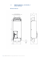
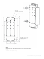
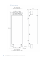
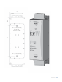
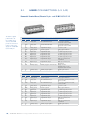
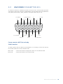
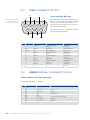
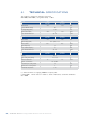
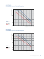
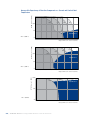
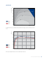
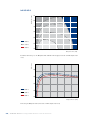
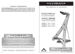
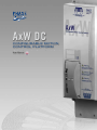
AxW DC
CONFIGURABLE MOTION
CONTROL PLATFORM
User Manual
AxW-DC
CONFIGURABLE MOTION
CONTROL PLATFORM
User Manual
Release 1.0
Summ
Summary
4 | AxW DC Series Configurable Motion Control Platform
mary
1 Mechanical Assembly
and Wiring
1.1 Overall dimensions and space
required for installation................. 8
1.2 Mounting options.......................... 9
2 Drive Configuration
2.1 Comunication set up and system
configuration............................. 14
2.2 Motor cabling and connection checkup
3 Electrical Connections
3.1
3.2
3.3
3.4
User Connectors (U1/U2)............
Encoder Connectors (E1)............
CAN Connectors (C1).................
RS232 Serial Connectors (S1).....
18
19
20
21
4 Technical
Specifications
Summary | 5
1
Mechanical
assembly and
wiring
Phase Motion Control
AxM-II / AxP Configurable Motion Control Platform
1.1
Mechanical Assembly
and wiring
AxW Overall dimensions
140
Power Supply DC Input
Tightening torque (brass M10 bolts) = 25Nm
95-120 mm2 power terminals
DC +
32
486
DC -
90
4 x M10
10
180
8 | AxW DC Series Configurable Motion Control Platform
GND
156
Water Output
1/4” Gas NPT, compression fitting
530
345
550
Water Input
1/4” Gas NPT, compression fitting
10
127
Coolant flow = 10 l/min
T°in max = 30°C
31
612
31
N°4 Fixing slots for M10 bolts
180
200
Wiring
Use Brass M10 bolts, 25Nm tightening torque with 95 / 120 mm2 power terminals
Cooling
Use ¼” Gas NPT compression fitting
Mechanical Assembly and Wiring | 9
FxW Overall dimensions
DRIVE SIDE CONNECTION
Use brass M10 bolts, tightning torque = 25Nm
95-120 mm2 Power Terminals
188
(34,5)
DC-
B
PTC
C
747
767
829
A
N° 4 holes
for lifting hooks
A
B
C
N° 4 holes
for ground
LINE SIDE CONNECTION
Use brass M10 bolts, tightning torque = 25Nm
95-120 mm2 Power Terminals
10 | AxW DC Series Configurable Motion Control Platform
90
235
180
138,5
117,5
490
Water Input
1/4” Gas, compression fitting
Coolant flow = 10 l/min
T°in max = 30°C
Max pressure 3 BAR
Water Output
1/4” Gas, compression fitting
Sezione | 11
2
Drive
configuration
Phase Motion Control
AxW DC Series Configurable Motion Control Platform
2.1
comunication set up and
system configuration
Configure your AxW according to your application request, upgrading (if necessary) the
system application and the parameters settings.
“Cockpit” is the tool intended for this job.
Insert the CD-Rom supplied with the drive in the PC and let the autorun work. If
it do not start please open the page “index.htm” in the CD root directory with
any Internet browser. It is also possible activate setup opening the “setup.exe”
file present in the folder
d:\ setup\axvsetup\disk1;
When setup is finished and PC restarted, the “AxV Cockpit” folder will be added
to the Windows menu “Start->Windows Programs”
A PC with Windows XP, 80Mbyte of free space, Internet Explorer 6.0 browser or
better and a RS 232 serial line is requested.
Cable connection is RS232 serial female to female, null modem (see pag. 10 for connections)
Auxiliary power supply 24V (22-30V) stabilized voltage 1A is necessary to supply the Drive.
PC Connection Schema
»» connect 24V supply on “+24V” and “0V” pins of the U1 terminal box (see pag. 6 for
connections schema).
»» Connect the RS 232 line to the connector S1 port
Switching on the 24V supply the drive will turn on and the configuration will become possible through “Cockpit” tool.
If no allarms are active the green led of the drive is blinking. Opening the system table
SyaApp-X-x.par or the application table with Cockpit tool, the connection should be
established automatically.
2.2
Motor cabling
and connection check-up
Encoder Connection
Connect the position sensor to E1 port, through a suitable multipolar shielded cable, according to the relative correspondence specified in the wiring table of par. 3.2.
Use a shielded cable with twisted duplexes, possibly of high flexibility type.
When the connection cable is longer than 25 m, the use of adequate cable section is recommended in order to avoid excessive voltage drops.
14 | AxW DC Series Configurable Motion Control Platform
WARNING:
The cable shield must be grounded both side connectin it to the motor ground screw and to the
drive connector frame.
Power connections
Connect the power supply to the DC+ and DC- input of the power terminal box. Connect the
motor phases A, B, C and the Ground wire to the terminals of the drive’s power terminal
box, according to the sequence specified in the connection outline supplied with the motor.
User connection
On U1 and U2 terminal box there is the analog and digital drive interface, complete of:
»»
»»
»»
»»
2
2
8
4
A shielded cable
must be used
for motor phases
connection and the
cable shield must
be grounded on both
sides, motor and
drive.
analog differential programmable inputs
analog programmable outputs
digital programmable inputs
digital programmable outputs
Check par. 3.1 for complete conenction sets
Field bus
On connector C1 there is the CAN bus interface as specified on par. 3.3
Drive Configuration | 15
3
ELECTRICAL
CONNECTIONS
Phase Motion Control
AxW DC Series Configurable Motion Control Platform
3.1
User Connectors (U1 /U2)
Remuvable Terminal Board, Phoenix 12 pin - cod. FK-MC 0.5/12-ST-2.5
To obtain a good
performance of
the analog input
connect the RxN
pin to the reference
(suorce side) and
apply the –10/+10V
to the RxP pin
USER CONNECTOR U1
N
Name
Type
Function
Signal description
1
R0P
Analog input
Direct differential input
+/-10V, Zin = 10Kohm,
if not used connect to GND
2
R0N
Analog input
Denied differential input
+/-10V, Zin = 10Kohm,
if not used connect to GND
3
AO0
Analog output
Programmable output
+/-10V f.s., 5 mA
4
GND
Analog ground
Reference ground
Analog signals reference
5
DI0
Digital input
Programmable input
6.6 kOhm to ground, 20-30 V
6
DI1
Digital input
Programmable input
6.6 kOhm to ground, 20-30 V
7
DI2
Digital input
Programmable input
6.6 kOhm to ground, 20-30 V
8
DI3
Digital input
Programmable input
6.6 kOhm to ground, 20-30 V
9
DO0
Digital output
Programmable output
PNP open collector, 24 V,
100mA max
10
DO1
Digital output
Programmable output
PNP open collector, 24 V,
100mA max
11
24V
Auxiliary supply
Auxiliary supply of control circuits
Voltage: 22-30 V
Referred to Pin 12 ( 0V)
Requested current: 500mA.
12
0V
Auxiliary supply
Auxiliary supply negative
Digital signal reference
N
Name
Type
Function
Signal description
13
GND
Analog ground
Reference ground
Analog signals Reference
14
R1P
Analog input
Direct differential input
+/-10V, Zin = 10Kohm, if not used,
connect to GND
15
R1N
Analog input
Direct differential input
+/-10V, Zin = 10Kohm, if not used,
connect to GND
USER CONNECTOR U2
16
AO1
Analog output
Programmable output
+/-10V f.s., 5 mA
17
GND
Analog ground
Reference ground
Analog signals Reference
18
DI4
Digital input
Programmable input
6.6 kOhm to ground, 20-30 V
19
DI5
Digital input
Programmable input
6.6 kOhm to ground, 20-30 V
20
DI6
Digital input
Programmable input
6.6 kOhm to ground, 20-30 V
21
DI7
Digital input
Programmable input
6.6 kOhm to ground, 20-30 V
22
DO2
Digital output
Programmable output
PNP open collector, 24 V,
100mA max
23
DO3
Digital output
Programmable output
PNP open collector, 24 V,
100mA max
24
0V
Auxiliary supply
Auxiliary supply negative
Digital signal reference
18 | AxW DC Series Configurable Motion Control Platform
3.2
Encoder Connector (E1)
To allow the connection of different encoders some pins of this connector have more than
one function. Select the connection corresponding to your encoder and set the parameters
SYS_ENC1_TYPE and SYS_ ENC1_CY_REV in the system table (see par. 3.4)
pin1- GND/PTC-
Sin+
Cos+/H1/EndatClock+
Cos-/H2/EndatClock-
1
2
9
3
10
Enc I-/EndatData-
Sin-/H3
4
11
5
12
ResExpResExp+
Vcc
Enc A+
6
13
Enc BEnc A-
PTC+/Kty
7
14
8
15
Enc B+
Enc I+/EndataData+
Cannon connector subD 15 pin, male plug
Shield Connection:
To obtain a good connection without noise problems it is necessary to connect the shield of
the encoder cable both on motor and drive side.
Motor side:
Drive side:
connect the shield to the apposite screws or in the terminal board
connect the shield to the connector body.
Electrical Connections | 19
3.3
CAN connector (C1)
CAN L
Pin1: B+
Connect the shied of
the encoder cable to
the connector body.
1
Shield
2
6
Cannon sub D9 pin, Male plug
AIndex-
3
7
4
8
B-
C1 connector can be used alternatively for
CAN line or to the auxiliary encoder signals;
You can connect either the CANopen net or
pick up the encoder emulation or use the inputs for auxiliary encoder.
5
9
The selection and the configuration is made
by some system parameters.
A+
CAN H
Index+
Pin
Name
Type
Function
Signal description
1
B+
Digital I/O
Encoder incremental
channel
TTL Differential
line driver
2
CAN L
Digital I/O
CAN interface
CAN positive signal
3
Schermo
Gnd
CAN cable Shield
Logic Ground
4
A-
Digital I/O
Encoder incremental
channel
TTL Differential
line driver
6
B-
Digital I/O
Encoder incremental
channel
TL Differential
line driver
7
CAN H
Digital I/O
CAN interface
CAN negative signal
8
A+
Digital I/O
Encoder incremental
channel
TL Differential
line driver
9
I+
Digital I/O
Encoder index
TL Differential
line driver
3.4
RS232 Serial Connector (S1)
Cannon connector sub D 9 pin, female plug
Standard RS 232 DCE ( + RS 485 )
Pin
Standard RS232
S1 connector
1
DCD
---
Description
2
RxD
RxD ( Rx-, A )
Data Line
3
TxD
TxD ( Tx-, A )
Data Line
100mA MAX
4
DTR
+12V
5
GND
GND
6
DSR
232 / 485
If +/-12V RS-232, if 0V RS-485
7
RTS
RTS ( Tx+, B )
Data Line
8
CTS
CTS ( Rx+, B )
Data Line
9
RI
---
20 | AxW DC Series Configurable Motion Control Platform
Electrical Connections | 21
4
Technical
Specifications
Phase Motion Control
AxW DC Series Configurable Motion Control Platform
4.1
Technical Specifications
Test conditions, where not differently specified:
VDC=700V, VAC=400V, cooling water temp. = 20°C
DC Side
Max DC Power
AxW
250.330.6
AxW
300.400.6
Unit
223
228
kW
Absolute MAX DC Voltage
950
Vdc
DC Voltage Range [VDC]
0 - 900
Vdc
Max DC Current [IDC]
245
297
Power Terminal Dimension
AC Side
Max AC Power
95 - 120
mm2
AxW
250.330.6
AxW
300.400.6
Unit
217
280
kW
(Vdc / sqrt(2)) - 10%
MAX AC Voltage [VAC]
Max AC Current
Arms
330
400
Arms
Max AC Frequency
1,2
kHz
Ripple Current Frequency
16
kHz
Power Terminal Dimension
95 - 120
Performance
AxW
250.330.6
Efficency
AxW
300.400.6
97,4 (*)
Water Cooling Temp. Range
Nominal Coolant Flow
mm2
%
18 - 60 (*!)
10
Water In / Out Interface
Unit
°C
15
l/min
1/4” Gas NPT
Pressure Drop in Cooling Circuit
0.5
bar
Max Pressure in Cooling Circuit
5
bar
0 - 40
°C
Environment Temperature
(*) – when the Drive is supplying 100KW of output power.
(*!) CAUTION: Never overcool in order to avoid condensation; see Curves referred to
Vac = 400V
24 | AxW DC Series Configurable Motion Control Platform
MAx Drive Currenr (Arms)
AxW 250.330.6
Continuos Drive Current vs. Water Inlet Temperature
300
250
200
VDC = (600 V)
150
VDC = (700 V)
VDC = (800 V)
100
10
20
30
40
50
60
70
Cooling Water Temperature (°C)
MAx Drive Currenr (Arms)
AxW 300.400.6
Continuos Drive Current vs. Water Inlet Temperature
400
350
300
250
200
VDC = (600 V)
VDC = (700 V)
150
VDC = (800 V)
100
10
20
30
40
50
60
70
Cooling Water Temperature (°C)
Technical Specifications | 25
MTBF [hours x 1.000]
Average Life Expectancy of Reactive Components vs. Current and Coolant Inlet
Temperature
50°C
1000
40°C
30°C
20°C
100
Output MAX Current
VDC = (800 V)
10
0
50
100
150
200
250
300
350
MTBF [hours x 1.000]
Output Effective Current (Arms)
30°C
40°C
50°C
60°C
1000
Output MAX Current
100
VDC = (700 V)
10
0
50
100
150
200
250
300
350
MTBF [hours x 1.000]
Output Effective Current (Arms)
10.000
40°C
50°C
60°C
Output MAX Current
1.000
VDC = (600 V)
100
200
250
300
350
400
Output Effective Current (Arms)
26 | AxW DC Series Configurable Motion Control Platform
DC Bus Voltage
AxW 250.330.6
900
96%
820
96,5%
VDC Max
720
97%
620
520
97,5%
VDC = (600 V)
420
VDC = (700 V)
VDC = (800 V)
320
0
100
50
150
200
Output Power [kW]
Efficiency
Converter efficiency loci Vs Output Power and DC link voltage (inclusive of FxW output filter
loss).
0,98
0,96
0,94
VDC = (600 V)
0,92
VDC = (700 V)
VDC = (800 V)
0,90
0
50
100
150
200
Output Power [kW]
Efficiency Vs Output Power (inclusive of FxW output filter loss).
Technical Specifications | 27
DC Bus Voltage
AxW 300.400.6
900
96%
820
VDC Max
96,5%
720
620
97%
520
97,5%
VDC = (600 V)
420
VDC = (700 V)
VDC = (800 V)
320
0
50
100
150
200
250
300
Output Power [kW]
Efficiency
Converter efficiency loci Vs Output Power and DC link voltage (inclusive of FxW output filter
loss).
0,98
0,96
0,94
VDC = (600 V)
0,92
VDC = (700 V)
VDC = (800 V)
0,90
0
50
100
150
200
250
Output Power [kW]
Efficiency Vs Output Power (inclusive of FxW output filter loss)
28 | AxW DC Series Configurable Motion Control Platform
Technical Specifications | 29
AxW-DC - Configurable Motion Control Platform
User Manual
English version
Release 1.0
RETE MONDIALE DI DISTRIBUZIONE
E ASSISTENZA
WORLDWIDE SUPPORT AND
DISTRIBUTION NETWORK
Company headquarters
Phase Motion Control S.p.a.
Via Adamoli 461
16141 Genova, Italy
www.phase.eu
www.phase.com.cn
Phase Automation (Ningbo) Ltd
North of Binhai Rd
Cixi Economic Development Zone
Ningbo 315336
www.phase.com.cn
Phase Motion Control, China
Phase Motion Control (Ningbo) Ltd
55, Putuoshan Rd,
Beilun Science and Technology Park
Ningbo 315800
Phase Motion Control, France
Phase Automation S.a.r.l.
20 Avenue Felix Faure
69007 Lyon
www.phase-automation.com
Phase Motion Control, U.S.A.
Phase USA, Inc.
1335 Industrial dr.
Itasca, IL 60143
www.PhaseUSA.com