1
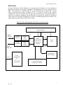
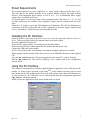
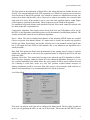
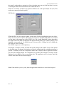
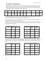
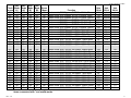
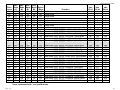
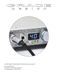
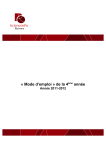
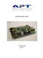
apt-X Evaluation CoDec.
User Manual
Rev 1.0
apt-X Evaluation CoDec
Issue Index
Rev 1.0 …………………………………………………..
Original Release.
1
Rev. 1.0
apt-X Evaluation CoDec
Overview
The apt-X Evaluation CoDec Module is for encoding and/or decoding one or two channels of
digital audio using any of the apt-X algorithms. The algorithms are run on a Motorola 56362
DSP. The module has an S/PDIF audio I/O section and the ability to Sample Rate Convert
(SRC) in both directions. Either a Windows ‘G.U.I.’ via USB, or a bank of ‘dip’ switches
configures the mode of operation for the module The module also has an expansion header to
enable users to interface equipment into the data path at certain points. This gives the ability to
bypass some of the on-board components. The power is normally supplied by an external 9v dc
supply needing a mains input via an IEC320/C8 lead.
(E)apt-X CoDec. Block Diagram of Data Flow and Control Paths
Expansion Header
Digital
Audio In
S/PDIF
Receiver
S/PDIF
Transmitter
Sample
Rate
Converter
Sample
Rate
Converter
PCM
Field
Programmable
Gate Array
(Xilinx)
Digital
Audio Out
+9v d.c.
apt-X
DSP
apt-X
Power
Sequencing
&
3.3v 2.5v
generation
Oscillators &
PLL Circuits
USB Connection &
Configuration Switches
2
Rev. 1.0
apt-X Evaluation CoDec
Getting Started
Test 1. This section describes how to configure the module for a simple apt-X loopback. The
data flow is as follows; the S/PDIF data is received the PCM data is extracted and supplied to the
DSP for encode via the FPGA. The encoded data is then returned to the DSP, again by the
FPGA, for decode. The PCM is then routed to the S/PDIF output stage and retransmitted at the
same sample frequency (Fs) as the input. This is known as a ‘Low Delay’ mode since the SRCs
are not being used, this mode will show the truest latency figures for the algorithm.
Before even connecting power to the module, the ‘jumpers’ or links must be set-up. L2 should be
set to connect pins 1 and 2. This sets the module to accept configuration from the dip switches.
Links J3, J4, J5 and J6 should all have jumpers on them, why this is the case is explained later.
The next step is to set the 10-way DIP switch as follows;
SW1-1 – On (Loopback)
SW1-2 -- Off
SW1-3 -- On
SW1-4 -- Off
SW1-5 -- Off
SW1-6 -- Off
SW1-7 -- Off
SW1-8 -- Off
SW1-9 -- On
SW1-10 – Off
The module is now configured for Eapt-X16, low delay loopback at Fs = 44.1kHz.
Once this configuration is set, powering on the module will set the unit up to take in a stereo
S/PDIF stream with an Fs of 44.1kHz, encode and decode it. Then return it out the S/PDIF out
port. A CD player is an ideal source for this first test.
Test 2. The next logical step is to loopback the data at the expansion header where it can be
examined as it goes past. To do this only requires one switch to be changed, SW1-1. Setting it to
the Off position removes the loopback of the encoded data inside the FPGA, instead the data is
routed out via a FIFO to pin 12 of the expansion header (Cn4). Connecting pin 12 to pin 13 of
Cn4 will again loopback the data from the encoder to the decoder. By placing oscilloscope
probes on pins 12 and 14 of Cn4 it is possible to ‘see’ the encoded (or compressed) apt-X data
and the clock associated with it.
The two tests above are the quickest to set up and will prove basic operation of the module;
however there are many more modes of operation the module is capable of. How to achieve all
of these are described in the following sections, which will explain the differences between
‘Master’ and ‘Slave’ modes as well as how to select between low delay and SRC modes. The
configuration is described from the perspective of configuration being done via the PC interface
software included with the board. An advanced description of how to achieve all these modes
using the DIP switches is included as the last section.
3
Rev. 1.0
apt-X Evaluation CoDec
Power Requirements
The preferred option is to use the supplied 9v d.c. power supply connected to the input ‘jack’.
This will then let the module generate all its required internal voltages; this input remains
effective with unregulated input voltages as low as 6.5v. It is recommended that a supply
voltage above 9v should not be used.
The second option is to power the unit via the expansion header CN4 where 5v, 3.3v, 2.5v and
0v(Gnd) connections are available. These supplied voltages must be regulated and free from
noise.
When the 3.3v supply is active the LD2 indication will illuminate. This will also illuminate on
connection of an active USB cable and is NOT a guarantee of all power supply voltages being
correct. The module CANNOT be powered using only the USB.
Installing the PC Interface
Before the Windows application can be used it is necessary to load the appropriate USB driver files on to
the PC. This process only needs to be completed once and is quite simple.
Insert the supplied CD into the PC.
Ensure that L2, on the module, is set with pins two and three linked.
Make sure the USB cable is not connected to the module and then power it up.
Connect the USB cable to the module.
The PC will now detect the ‘new hardware’ and start the standard windows driver install.
When prompted for the location of the driver, browse to the DRIVERS directory on the supplied
CD.
Copy the apt_eval.exe from the CD onto an appropriate place on the PC, such as ‘Desktop’.
Run the apt_eval.exe file. This will now bring up a new window with all the configuration
options shown.
Using the PC Interface.
This method of configuration is using the supplied Windows application via the USB port on the
module. To ensure correct operation of this mode L2, on the module, must have pins two and
three linked and the DIP switches must all be in the OFF position. Once the module has been set
up and powered on, the USB cable can be connected and then the configuration application
(apt_eval.exe) can then be opened.
When it opens, the application will be in the default mode, as shown.
4
Rev. 1.0
apt-X Evaluation CoDec
The first option on the application is Master/Slave, this setting depends on whether the unit is to
SLAVE to an external network clock (DTE operation), or is allowed to generate its own network
clock for the apt-X data.(DCE operation.) For example to connect two modules back to back, one
needs to be a master and the other a slave. However, to connect two modules via a network, both
units need to be slaves. If the module is set as a slave the clock supplied must be within 50ppm
of the frequency specified for that mode. These frequencies can be found in the appendix.
For standalone loop-backs Master mode should be selected. Slave mode cannot be selected with
low delay mode this is explained later.
Compression Algorithm. This simply selects which of the four apt-X algorithms will be run by
the DSP. As the algorithm resolution increases so will the amount of encoded data produced. The
encoder and decoder cannot be set for different algorithms.
Stereo / Mono. This selects whether both channels of the incoming S/PDIF stream are encoded
(Stereo) or just the first channel (Mono). If a mono mode is chosen, the encoder only produces
half the apt-X data. Equivalently, the decoder will only receive one channels worth of apt-X data
but it will output the same PCM to both channels, this is not inherent to the algorithm but is
usually desirable.
Data Path. This option has already been demonstrated in the ‘getting started’ section. It controls
whether the encoded data is sent out to the expansion header or looped by the FPGA and sent
back to the DSP.
Autosync Check box. This control only becomes active when the apt-X16 algorithm is selected.
This is because Autosync cannot be turned off in the enhanced algorithms. Autosync is a very
low overhead embedded code which allows the apt-X stream of data to travel without the need
for a framing or word clock. Some very early APT products worked without Autosync as
framing information could be recovered from other sources. Non Autosync mode and how to
frame it are discussed later. It is recommended that it be left on at all times.
Low Delay Mode.
This mode can only be used if the unit is configured in Master mode. The low delay is achieved
at the cost of bypassing the SRCs in and out of the module. This means the DSP MUST run at
5
Rev. 1.0
apt-X Evaluation CoDec
the same Fs as the audio is coming in at. Since the audio comes in at a fixed rate there is no way
of slaving the DSP to different network rate without the SRCs.
When in ‘Low Delay’ mode the only option available to set is the input sample rate (Fsi). This
needs set to ensure good audio quality.
SRC Modes.
When the SRCs are in circuit the module is much more flexible regarding data rates and clocks.
There are now two more options which need set. The first is the audio bandwidth to be encoded
and the other is the output rate of the S/PDIF. (Fso) The ‘Audio Bandwidth’ setting determides
the sample rate of the DSP and therefore the amount encoded data. For example, assume 16 bit
algorithm, stereo mode. At Fs=16kHz the apt-X bit rate will be 128kbps but at Fs=48kHz the
apt-X bit rate will be 384kbps.
The S/PDIF output rate is self explanatory.
Pressing the ‘Configure’ button will send the current settings to the module. If any of the options
in the application are changed, the hardware will not be updated until the configuration button is
pressed. A summary of the last configuration mode sent is displayed in the application window
just above the configure button. If a configuration is rejected by the hardware, a message will be
displayed in the middle of the screen stating this. The application will be inactive until the
window shown here has been acknowledged.
Note: If the module is power cycled, then the application should also be closed and reopened.
6
Rev. 1.0
apt-X Evaluation CoDec
Dip Switch Configuration
This method is for stand-alone mode, where no PC with a USB port is available. In this mode the
module configuration is set by the ten-way DIP switches, that are labelled ‘Configuration’ on the
PCB. To enable stand-alone mode the ‘jumper’ on L2 must be moved to link pins one and two.
The functionality of each switch is shown in the table below.
Switch
No
10
9
8
7
6
5
4
3
2
1
Stereo
Mono
SRC
Mode
B1
SRC
Mode
B0
SRC
Mode
A1
SRC
Mode
A0
Clock
Mode
Algorithm
Select 1
Algorithm
Select 0
A’sync
On/Off
aptX16
Loop
Back
The Stereo/Mono switch is Off for Stereo and On for Mono the operational changes are the same
as the equivalent radio button group on the windows application.
The SRC mode switches 9 to 6 are a little more complex in operation. The function of switches 9
and 8 depend on the settings of switches 7 and 6.
If switches 7 and 6 are OFF this means the module is in ‘Low Delay’ mode. The function of
switches 9 and 8 are then to set-up the module for the appropriate incoming sample rate. The table
below shows the exact settings.
Switches 7 & 6
Mode
SRC
Mode A1
SRC Bypass
Off
SRC
Mode A0
Off
Switches 9 & 8 if SRC Bypass selected
Mode
SRC
SRC
Mode
Mode
B1
B0
S/PDIF 48kHz
Off
Off
In
S/PDIF 32kHz
Off
On
In
S/PDIF
On
Off
44.1kHz In
S/PDIF 48kHz
On
On
In
Any other setting of switches 7 and 6 will configure the module for SRC mode. This means that
switches 7 and 6 set-up the rate of the S/PDIF output. Switches 9 and 8 are now used to select the
audio bandwidth to be encoded / decoded. The table below shows the precise settings for each
mode.
Switches 7 & 6
Mode
SRC
Mode A1
S/PDIF
32kHz Out
S/PDIF
44.1kHz Out
S/PDIF
48kHz Out
SRC
Mode A0
Switches 9 & 8 if SRC mode selected
Mode
SRC
SRC
Mode
Mode
B1
B0
7kHz
Off
Off
Off
On
12kHz
Off
On
On
Off
15kHz
On
Off
On
On
20kHz
On
On
7
Rev. 1.0
apt-X Evaluation CoDec
Switch 5 is the Master Slave selection. On for Slave and Off for Master. As explained earlier for
the PC interface, it is impossible to run the module in ‘Slave’ mode while ‘Low Delay is
selected. This is why the PC interface will not allow the user to send that configuration. The DIP
switches can be set for this invalid mode but the module will not run properly. If the switch is On
then the module is in ‘Slave’ mode. This means the unit needs an external clock at the
appropriate rate supplied to it. If the switch is Off, the module is in Master mode and will
provide a clock at the data rate.
Switches 4 and 3 are used for Algorithm selection. The exact settings are shown below.
Mode
apt-X 16bit
Algorithm
Select 1
Off
Algorithm
Select 0
Off
Off
On
On
Off
On
On
Eapt-X
16bit
Eapt-X
20bit
Eapt-X
24bit
Switch 2 controls the use of Autosync when the apt-X16 algorithm is selected. If any other
algorithm is selected Autosync can not be turned off so the state of this switch is irrelevant. For
apt-X16 if the switch is On then Autosync is On.
Switch 1 controls the flow of the apt-X data. If the switch is ON then the data is looped so the
DSP decodes what it has just encoded. If the switch is Off then the encoded data goes out to the
expansion header and data for decode is expected from the expansion header.
Additional Information
Since this module has been designed as a platform to show the excellent audio quality properties
of the apt-X algorithms, some of the flexibility of use has been omitted in order to achieve the
best possible audio quality. One example of this is the use of the precision VCXO’s which
enable the module to provide an S/PDIF output with jitter below 2nS (Fs = 48kHz), even if the
input jitter is much higher. The penalty of this however, is the low tolerance to clocks which are
above or below the frequency specified for any particular mode. The VCXO’s only have a ‘pull’
of 100p.p.m, this is why the clock provided to a module in slave mode, must be accurate and
stable.
The following pages show the switch settings for all the modes and the associated clocks that are
generated / required. The data clock must match the data rate, for example 384kb/s needs a
384kHz clock.
The modes highlighted with a grey background are functional, however there is little point
running the DSP set for 20kHz when the incoming bandwidth is restricted to 15kHz by the
32kHz incoming sample rate.
An electronic copy of the module’s schematic is included on the supplied CD ‘apt-X Eval.SCM’
To view this requires CADSTAR 5.0 or greater, alternatively there is a viewer available FREE at
http://www.cadstarworld.com/down_viewer6.asp
8
Rev. 1.0
apt-X Evaluation CoDec
SRC SRC SRC SRC
Clock Mode Mode Mode Mode Stereo
source A1
A0
B1
B0 / Mono
Off
Off
Off
Off
Off
Off
Off
Off
Off
Off
Off
On
Off
Off
Off
Off
On
Off
Off
Off
Off
Off
On
On
Off
Off
Off
On
Off
Off
Off
Off
Off
On
Off
On
Off
Off
Off
On
On
Off
Off
Off
Off
On
On
On
Off
Off
On
Off
Off
Off
Off
Off
On
Off
Off
On
Off
Off
On
Off
On
Off
Off
Off
On
Off
On
On
Off
Off
On
On
Off
Off
Off
Off
On
On
Off
On
Off
Off
On
On
On
Off
Off
Off
On
On
On
On
Off
On
Off
Off
Off
Off
Off
On
Off
Off
Off
On
Off
On
Off
Off
On
Off
Off
On
Off
Off
On
On
Off
On
Off
On
Off
Off
Off
On
Off
On
Off
On
Off
On
Off
On
On
Off
Off
On
Off
On
On
On
Off
On
On
Off
Off
Off
Off
On
On
Off
Off
On
Off
On
On
Off
On
Off
Off
On
On
Off
On
On
Off
On
On
On
Off
Off
Off
On
On
On
Off
On
Off
On
On
On
On
Off
Off
On
On
On
On
On
kb/s
Function
16 bit
Master mode, SRC Bypass, S/PDIF in 48kHz, Stereo
384
Master mode, SRC Bypass, S/PDIF in 48kHz, Mono
192
Master mode, SRC Bypass, S/PDIF in 32kHz, Stereo
256
Master mode, SRC Bypass, S/PDIF in 32kHz, Mono
128
Master mode, SRC Bypass, S/PDIF in 44.1kHz, Stereo 352.8
Master mode, SRC Bypass, S/PDIF in 44.1kHz, Mono 176.4
Master mode, SRC Bypass, S/PDIF in 48kHz, Stereo
384
Master mode, SRC Bypass, S/PDIF in 48kHz, Mono
192
Master mode, SRC, S/PDIF out 32kHz, 7kHz Stereo
128
Master mode, SRC, S/PDIF out 32kHz, 7kHz Mono
64
Master mode, SRC, S/PDIF out 32kHz, 12kHz Stereo
192
Master mode, SRC, S/PDIF out 32kHz, 12kHz Mono
96
Master mode, SRC, S/PDIF out 32kHz, 15kHz Stereo
256
Master mode, SRC, S/PDIF out 32kHz, 15kHz Mono
128
Master mode, SRC, S/PDIF out 32kHz, 20kHz Stereo
384
Master mode, SRC, S/PDIF out 32kHz, 20kHz Mono
192
Master mode, SRC, S/PDIF out 44.1kHz, 7kHz Stereo
128
Master mode, SRC, S/PDIF out 44.1kHz, 7kHz Mono
64
Master mode, SRC, S/PDIF out 44.1kHz, 12kHz Stereo 192
Master mode, SRC, S/PDIF out 44.1kHz, 12kHz Mono
96
Master mode, SRC, S/PDIF out 44.1kHz, 15kHz Stereo 256
Master mode, SRC, S/PDIF out 44.1kHz, 15kHz Mono 128
Master mode, SRC, S/PDIF out 44.1kHz, 20kHz Stereo 384
Master mode, SRC, S/PDIF out 44.1kHz, 20kHz Mono 192
Master mode, SRC, S/PDIF out 48kHz, 7kHz Stereo
128
Master mode, SRC, S/PDIF out 48kHz, 7kHz Mono
64
Master mode, SRC, S/PDIF out 48kHz, 12kHz Stereo
192
Master mode, SRC, S/PDIF out 48kHz, 12kHz Mono
96
Master mode, SRC, S/PDIF out 48kHz, 15kHz Stereo
256
Master mode, SRC, S/PDIF out 48kHz, 15kHz Mono
128
Master mode, SRC, S/PDIF out 48kHz, 20kHz Stereo
384
Master mode, SRC, S/PDIF out 48kHz, 20kHz Mono
192
kb/s
kb/s
20 bit
24 bit
Loopback Loopback
Loopback Loopback
Loopback Loopback
Loopback Loopback
Loopback Loopback
Loopback Loopback
Loopback Loopback
Loopback Loopback
*
*
*
*
240
288
120
144
320
384
160
192
480
576
240
288
*
*
*
*
240
288
120
144
320
384
160
192
480
576
240
288
*
*
*
*
240
288
120
144
320
384
160
192
480
576
240
288
Items commented with * are invalid modes
Rev. 1.0
9
apt-X Evaluation CoDec
SRC SRC SRC SRC
Clock Mode Mode Mode Mode Stereo
source A1
A0
B1
B0 / Mono
On
Off
Off
Off
Off
Off
On
Off
Off
Off
Off
On
On
Off
Off
Off
On
Off
On
Off
Off
Off
On
On
On
Off
Off
On
Off
Off
On
Off
Off
On
Off
On
On
Off
Off
On
On
Off
On
Off
Off
On
On
On
On
Off
On
Off
Off
Off
On
Off
On
Off
Off
On
On
Off
On
Off
On
Off
On
Off
On
Off
On
On
On
Off
On
On
Off
Off
On
Off
On
On
Off
On
On
Off
On
On
On
Off
On
Off
On
On
On
On
On
On
Off
Off
Off
Off
On
On
Off
Off
Off
On
On
On
Off
Off
On
Off
On
On
Off
Off
On
On
On
On
Off
On
Off
Off
On
On
Off
On
Off
On
On
On
Off
On
On
Off
On
On
Off
On
On
On
On
On
On
Off
Off
Off
On
On
On
Off
Off
On
On
On
On
Off
On
Off
On
On
On
Off
On
On
On
On
On
On
Off
Off
On
On
On
On
Off
On
On
On
On
On
On
Off
On
On
On
On
On
On
Function
Invalid mode
Invalid mode
Invalid mode
Invalid mode
Invalid mode
Invalid mode
Invalid mode
Invalid mode
Slave mode, SRC, S/PDIF out 32kHz, 7kHz Stereo
Slave mode, SRC, S/PDIF out 32kHz, 7kHz Mono
Slave mode, SRC, S/PDIF out 32kHz, 12kHz Stereo
Slave mode, SRC, S/PDIF out 32kHz, 12kHz Mono
Slave mode, SRC, S/PDIF out 32kHz, 15kHz Stereo
Slave mode, SRC, S/PDIF out 32kHz, 15kHz Mono
Slave mode, SRC, S/PDIF out 32kHz, 20kHz Stereo
Slave mode, SRC, S/PDIF out 32kHz, 20kHz Mono
Slave mode, SRC, S/PDIF out 44.1kHz, 7kHz Stereo
Slave mode, SRC, S/PDIF out 44.1kHz, 7kHz Mono
Slave mode, SRC, S/PDIF out 44.1kHz, 12kHz Stereo
Slave mode, SRC, S/PDIF out 44.1kHz, 12kHz Mono
Slave mode, SRC, S/PDIF out 44.1kHz, 15kHz Stereo
Slave mode, SRC, S/PDIF out 44.1kHz, 15kHz Mono
Slave mode, SRC, S/PDIF out 44.1kHz, 20kHz Stereo
Slave mode, SRC, S/PDIF out 44.1kHz, 20kHz Mono
Slave mode, SRC, S/PDIF out 48kHz, 7kHz Stereo
Slave mode, SRC, S/PDIF out 48kHz, 7kHz Mono
Slave mode, SRC, S/PDIF out 48kHz, 12kHz Stereo
Slave mode, SRC, S/PDIF out 48kHz, 12kHz Mono
Slave mode, SRC, S/PDIF out 48kHz, 15kHz Stereo
Slave mode, SRC, S/PDIF out 48kHz, 15kHz Mono
Slave mode, SRC, S/PDIF out 48kHz, 20kHz Stereo
Slave mode, SRC, S/PDIF out 48kHz, 20kHz Mono
kb/s
16 bit
*
*
*
*
*
*
*
*
128
64
192
96
256
128
384
192
128
64
192
96
256
128
384
192
128
64
192
96
256
128
384
192
kb/s
20 bit
*
*
*
*
*
*
*
*
160
80
240
120
320
160
480
240
160
80
240
120
320
160
480
240
160
80
240
120
320
160
480
240
kb/s
24 bit
*
*
*
*
*
*
*
*
192
96
288
140
384
192
576
288
192
96
288
140
384
192
576
288
192
96
288
140
384
192
576
288
Items commented with * are invalid modes
Rev. 1.0
10