1
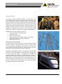
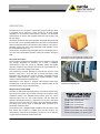
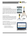
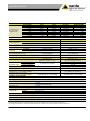
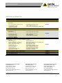
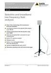
ELECTRIC AND MAGNETIC FIELD ANALYZER EHP-50F Selective and broadband low frequency field analysis Precise measurement of electric and magnetic fields with just one device Wide frequency range from 1 Hz to 400 kHz with high measurement dynamic range FFT method for selective and wideband measurement in all 3 spatial directions Weighted Peak measurements in accordance with ICNIRP 2010, ICNIRP 1998 and EMF Directive 2013/35/EU Time domain measurement method for exact capture of complex signal shapes Optical interface for remote control and result display avoids distortion of the field under test Autonomous measurement operation for up to 24 hours with built in data logger Control and display using a PC or the NBM-550 Broadband Field Meter EHP-50F NSTS 0115-E0310B 1/7 Subject to change without notice APPLICATION Low frequency fields are present throughout our environment. They occur wherever electrical energy is generated, distributed or used. Thus, they are present in our homes, our places of work, in medical facilities, and even outside in the open air where high-tension cables for energy distribution may be found. Magnetic fields occur primarily wherever high currents flow; electric fields wherever high voltages are present. It is virtually impossible to avoid their influence, which makes it all the more important to understand how they affect us and to prevent possible interactions by means of measurement and suitable countermeasures. Fields occur when electrical energy is generated Examples of places where strong LF fields occur: Power supply stations and transformers High-tension lines Electric motors, railroads Industrial equipment for welding, tempering, and smelting Galvanizing equipment, chlorine manufacturing Medical technology, MRT Fixed limit values for protection To protect people at work, the European Union has issued the EMF Directive 2013/35/EU. This obligates every company in the EU to carry out a risk assessment with regard to field exposure for every place of work. Mandatory minimum limit values for fields have been set, which come into force and must be met by mid-2016 at the latest. … where electrical energy is distributed International standardization bodies and organizations such as WHO, ICNIRP, IEC, IEEE, and CENELEC, as well as national authorities have for many years been working on establishing and updating the immission protection limit values or on product standards. There is no dispute about the short-term effects of high frequency and low frequency fields. Limits for the general public and in the workplace are in force practically everywhere around the world. However, such limit values on their own are not enough to protect people. They must also be verified by calibrated measurement to make certain. … and where electrical energy is used NSTS 0115-E0310B 2/7 Subject to change without notice DESCRIPTION The EHP-50F is a LF analyzer in a particularly compact package, which is equipped with E field and H field sensors for all three spatial dimensions. It can therefore make frequency selective, non-directional measurements of electric and magnetic fields with high accuracy and dynamic range. The built in tripod bush and remote operation via optical cable mean that the EHP-50F can be optimally positioned at the place of measurement without causing distortion in the field due to the presence of any person. Operation can be from a PC using Windows® based software or from the Narda NBM-550 basic unit. The EHP-50F can perform fully automatic long-term measurements for up to 24 hours in stand-alone operation, storing the results in the device itself. FFT spectrum analysis The limit values for electromagnetic fields in the low frequency range are very strongly dependent on frequency. As a result, a wideband measurement is often not enough to sufficiently assess the signals. Spectrum analysis is then needed. This shows the exact distribution of frequency components making up the signal. The powerful FFT analysis provided by the EHP-50F covers a broad frequency range from 1 Hz to 400 kHz in several sub-ranges. Lower frequencies are captured with a narrow resolution bandwidth and high resolution; higher frequency ranges use broader resolution, which results in faster measurement performance. Measurement of the electric or magnetic field spectrum takes place simultaneously in all axes and also gives the wideband value for the recorded frequency range at the same time. Weighted Peak method WPM The kinds of field signal sequences that are encountered are becoming more and more complex, such as those caused by current pulses during resistance welding. The Weighted Peak method gives the correct measured value even for such pulsed signals, and also takes the phases of the different frequency components into account. This saves users a lot of work, since they only need to select the relevant standard. The device then directly gives a meaningful result expressed as a percentage of the limit value. The EHP-50F uses a Weighted Peak evaluation with convolution in the time domain that conforms to ICNIRP 2010 and IEC 61786-2. The measurement covers the entire frequency range from 1 Hz to 400 kHz. A graph shows the measured value versus time. NSTS 0115-E0310B 3/7 The compact case of the EHP-50F contains all the technology for measuring E fields and H(B) fields Occupational safety personnel check the EMF immission of industrial plant Weighted Peak method for EHP-50F, complies with IEC 61786-2 For exposure evaluation according to: ICNIRP 1998, general public ICNIRP 1998, occupational ICNIRP 2010, general public ICNIRP 2010, occupational Directive 2013/35/EU, Limbs Action Levels Directive 2013/35/EU, High Action Levels Directive 2013/35/EU, Low Action Levels Subject to change without notice CONTROLLING THE EHP-50F Controlling measurements from NBM-550 All the major measurement functions of the EHP-50F can be remote controlled from the NBM-550 Field Measuring Set. To do this, the EHP is connected to the NBM using an optical control cable (POF duplex). The NBM then displays the measured values transferred from the EHP. The NBM offers distinct operating advantages over a laptop in harsh environments or in strong sunlight. The measurement data is saved in the NBM and can subsequently be evaluated and documented using the NBM-TS PC software. This measurement solution is particularly advantageous to all users wanting to measure RF fields as well as LF fields. Stand-alone mode measurements This operating mode is ideal for long-term measurements, allowing a recording time of up to 24 hours without the need for an additional power supply. The analyzer is preconfigured using the software and can then measure the wideband value or the maximum value occurring in the spectrum (E or H field). In this way, up to two measured values per minute are saved to the data logger fully automatically. These can be read out and evaluated at a convenient time later on. Measurement controlled by NBM-550 Controlling measurements from PC The EHP-50F can be operated directly through the optical cable by remote control from a Windows based PC running the EHP50-TS software. This measurement solution is ideal for the laboratory environment and for detailed display of the result spectrums. The EHP50-TS software provides additional measurement features when compared with control from the NBM, such as: Spectrogram and waterfall displays Isotropic spectrum and additional display of X, Y, Z Simultaneous E field and H field measurement Measurement of electrical signals (via Aux input) Measurement controlled by PC with EHP50-TS NSTS 0115-E0310B 4/7 Subject to change without notice SPECIFICATIONS EHP-50F Measurement principle Field sensors Fast Fourier Transformation for frequency domain measurements (1024 point FFT) Shaped Time Domain STD with peak detector for Weighted Peak Orthogonally arranged coils for the magnetic field (sensor area 35 cm2) Orthogonally arranged plate electrodes for the electric field (sensor area 50 cm2) FEATURES AND FUNCTIONS EHP-50F Control Spectrum analysis with marker evaluation Measurement functions NBM-550 PC software EHP50-TS Spectrum, isotropic Spectrum, isotropic and X,Y,Z Standard, isotropic Standard, isotropic and X,Y,Z (spectrum related to a standard, displayed in percent) (spectrum related to a standard, displayed in percent) Isotropic; max. 6 Hz … 100 kHz (Span 0.5/1/2/10/100 kHz) Isotropic and X,Y,Z Wideband Weighted Peak Weighted Peak according IEC 61786-2 (time domain), selectable standards Additionally selectable standards to be displayed as a limit trace or as a standard related spectrum (more standards can be added by the user) Spectrum Highest Peak or Wideband PC software Spectrum analysis and Standard Result type/ acquisition - Spectrogram Highest Peak (highest spectral line) Data logging with Auto Save Stand-alone mode without display Highest Peak or Wideband Weighted Peak (graph over time) Averaging method AUX signal input Data interface NSTS 0115-E0310B Isotropic or X,Y,Z with graph over time EMF Directive 2013/35/EU, Limbs Action Levels EMF Directive 2013/35/EU, High Action Levels EMF Directive 2013/35/EU, Low Action Levels ICNIRP 2010 Occupational ICNIRP 2010 General Public ICNIRP 1998 Occupational ICNIRP 1998 General Public GB8702 General Public BGV B11 Area 2h/d BGV B11 Area 2 BGV B11 Area 1 Safety Code 6 1999 RF Work IEC C95.6-2002 Gen. Public Safety Code 6 1999 Gen Pub IEC C95.6-2002 Occupation As a spectrogram or as separate text files for each spectrum Programmable timer Storage interval 1 s to 6 min Battery life > 9 h “EHP50-TS” “NBM-TS” Measurement, evaluation Evaluation, report and export and save to file Actual value (sample) Average Max Hold - - - Storage interval 30/ 60 s Battery life 24 h “EHP50 Logger” Configuration, read-out and save to file Actual value (sample) RMS/linear/median averaging 200 values, rolling memory, 100 values, rolling memory, time span 100 s to 2000 s time span 100 s to 1000 s Moving RMS average Moving RMS average RMS, linear and median over all values over 4/8/16 or 32 values over 30 s to 30 min Single channel input for analyzing electrical signals ranging from 30 nV to 1 V. The measurement must be controlled by the PC software EHP50-TS. Coaxial jack type MMCX, input impedance 1 kΩ Measurement control using the NBM-550 display unit or the PC software Optical POF interface, duplex 2 x 1000 µm RP-02, 38400 Baud, up to 40 m length Note: user specific remote operation is not supported 5/7 Subject to change without notice FREQUENCY All measurement functions except Weighted Peak Fstart 4800 Hz 1200 Hz 120 Hz 24 Hz 12 Hz 6 Hz 2.4 Hz 1 Hz Range (SPAN) a) 400 kHz 100 kHz 10 kHz 2 kHz 1 kHz 500 Hz a) 200 Hz a) 100 Hz Fstop 400 kHz 100 kHz 10 kHz 2 kHz 1 kHz 500 Hz 200 Hz 100 Hz Weighted Peak mode LEVEL Electric Field Magnetic Field Low Range 5 mV/m to 1 kV/m 0.3 nT to 100 μΤ High Range 500 mV/m to 100 kV/m 30 nT to 10 mT 200 kV/m 20 mT Overload limit Dynamic range Display resolution (NBM-550) Low Range High Range DANL displayed average noise level (f ≥ 50 Hz and SPAN ≤ 1 kHz) E/H field immunity UNCERTAINTY b) Expanded measurement uncertainty c) 106 dB 110 dB 4 digits, ≥ 1 mV/m 4 digits, ≥ 0.1 nT 4 digits, ≥ 0.1 V/m 4 digits, ≥ 0.1 µT 5 mV/m (isotropic) 3 mV/m (single axis) 0.3 nT (isotropic) 0.2 nT (single axis) < 10 V/m @ 1 mT (H field) < 0.2 µT @ 20 kV/m (E field) Electric Field ±9 % (typ. ±5 %) Magnetic Field ±5.6 % (typ. ±3 %) @ 40 Hz to 100 kHz, ≥ 200 nT ±0.7 dB ±0.35 dB ±0.7 dB ±0.2 dB ( 200 nT to 10 mT) @ 40 Hz to 100 kHz, ≥ 1 V/m 5 Hz to 40 Hz 40 Hz to 100 kHz 100 kHz to 400 kHz Linearity (referred to 100 V/m, 2 µT) Flatness @ 100 V/m, 2 μΤ ±0.35 dB (5 Hz to 400 kHz) ±0.2 dB (1 V/m to 1 kV/m) Isotropic response ±0.54 dB typ. Temperature deviation (typ. at 55 Hz) (referred to 23 °C, 50 % relative humidity) Humidity deviation (typ. at 55 Hz) (referred to 23 °C, 50 % relative humidity) GENERAL SPECIFICATIONS -0.004 dB/°C (-20 °C to 55 °C) +0.011 dB/% (10 % - 50 % humidity) +0.022 dB/% (50 % - 90 % humidity) ±0.12 dB typ. -0.008 dB/°C (-20 °C to 23 °C) +0.013 dB/°C (23 °C to 55 °C) -0.007 dB/% (10 % - 50 % humidity) +0.01 dB/% (50 % - 90 % humidity) Recommended calibration interval 24 months (calibration data stored in the internal EEPROM) Tripod support Threaded insert UNC ¼“ Internal battery Li-Ion, rechargeable, 3.7 V / 5.4 Ah > 9 hours 24 hours in stand-alone mode < 6 hours Operating time Recharging time External supply Temperature Bandwidth RBW 3600 Hz 900 Hz 90 Hz 18 Hz 9 Hz 4.5 Hz 1.8 Hz 0.9 Hz 1 Hz to 400 kHz b) Level range (manual selection) Resolution 976.56 Hz 244.14 Hz 24.414 Hz 4.8828 Hz 2.4414 Hz 1.2207 Hz 0.48828 Hz 0.24414 Hz Operation Storage Charging 10 to 15 VDC, 500 mA (barrel connector 3.5/1.35 mm positive pole inside) -20 °C to +55 °C -30 °C to +75 °C 0 °C to + 40 °C Humidity (operation) 0 to 95 % relative humidity, non-condensing Dimensions (H x W x D) 109 mm x 92 mm x 92 mm (without tripod) Weight 550 g (without tripod) Country of origin Italy a) Not available for Stand-alone operation b) Unless otherwise stated, these specifications apply for an ambient temperature of 23 °C and a relative humidity of 50 % c) Uncertainty includes flatness, linearity and isotropic deviations for a continuous wave signal (CW) and a confidence level of 95 % NSTS 0115-E0310B 6/7 Subject to change without notice ORDERING INFORMATION EHP-50F Part number Option for NBM-550 EHP-50F E&H Field Analyzer Set, 1Hz-400kHz, for NBM-550 Set includes: - EHP-50F Basic unit - O/E Converter USB, RP-02/USB - EHP-TS PC Software (Manual on CD) - Optical Bridge Connector RP-02 - Tripod Extension, 0.50m - Cable, FO Duplex, RP-02, 10m - AC/DC Battery Charger - Foam inserts for EHP-50 (to fit into NBM case) - Certificate of calibration 2404/103 Stand-alone / PC version EHP-50F E&H Field Analyzer Set, 1Hz-400kHz, Stand-alone/PC use Set includes: - EHP-50F Basic unit - O/E Converter USB, RP-02/USB - EHP-TS PC Software - Optical Bridge Connector RP-02 - Tripod Extension, 0.50m - Cable, FO Duplex, RP-02, 10m - Mini Tripod, Benchtop - Soft carrying case - AC/DC Battery Charger - User manual EHP-50 (printed) - Certificate of calibration Complete set with NBM-550 NBM-500 Set 13, 1Hz-6GHz, with EHP-50F, NBM-550, EF0691 Set includes: - NBM-550 Basic Unit - EHP-50F Basic Unit - Hardcase NBM Series, 5 Probes - Foam Inserts for EHP-50 (to fit into NBM case) - Power Supply 9VDC, 100V-240VAC - EHP-TS PC Software - Battery, Rechargeable, NiMH - Tripod Extension, 0.50m - Shoulder Strap, 1m - AC/DC Battery Charger - Tripod, Benchtop, 0.16m - O/E Converter USB, RP-02/USB - Cable, USB Interface - Cable, FO Duplex, RP-02, 10m - Software, NBM-TS - Optical Bridge Connector RP-02 - Operating Manual NBM-550 - Tripod, Non-Conductive, 1.65m - Probe EF 0691, E-Field - Certificates of calibration Optional accessories Tripod, Non-Conductive, 1.65m with Carrying Bag O/E Converter RS232, RP-02/DB9 Cable, FO Duplex, RP-02, 2m Cable, FO Duplex, RP-02, 20m Narda Safety Test Solutions GmbH Sandwiesenstrasse 7 72793 Pfullingen, Germany Phone: +49 7121 9732 0 Fax: +49 7121 9732 790 E-Mail: [email protected] www.narda-sts.com with Carrying Bag Narda Safety Test Solutions 435 Moreland Road Hauppauge, NY 11788, USA Phone: +1 631 231-1700 Fax: +1 631 231-1711 E-Mail: [email protected] www.narda-sts.us 2404/104 2400/113 2244/90.31 2260/90.06 2260/91.02 2260/91.03 Narda Safety Test Solutions Srl Via Leonardo da Vinci, 21/23 20090 Segrate (Milano) - Italy Phone: +39 02 2699871 Fax: +39 02 26998700 E-Mail: [email protected] www.narda-sts.it ® Names and Logo are registered trademarks of Narda Safety Test Solutions GmbH and L3 Communications Holdings, Inc. – Trade names are trademarks of the owners. NSTS 0115-E0310B 7/7 Subject to change without notice