1
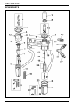
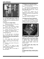
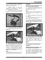
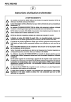
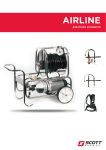
AFU 300/600
Operating and Maintenance Instructions
WARNINGS
These units are intended for use in industrial compressed air systems ONLY. DO NOT use for fluids
other than ambient air.
The air supply must be dry enough to avoid the formation of ice at temperatures below +2°C.
AFU 300/600 units ARE NOT suitable for use where carbon monoxide, carbon dioxide or other toxic
gases may be present in the air supply.
DO NOT use AFU 300/600 where pressures and temperatures can exceed those stated in the
Specification table overleaf.
DO NOT use if the ambient temperature is outside of the range 0°C to +40°C.
The use of AFU 300/600 DOES NOT guarantee breathing quality air unless regular air quality checks
are carried out to ensure that the air supplied conforms to EN 12021.
It is a requirement that regular air quality checks are carried out to ensure that the air supplied
conforms to EN 12021. Scott Health and Safety Limited recommends that these checks are
performed on at least a monthly basis.
ALWAYS site the air compressor intake in a clean-air zone and ensure that the compressor is well
maintained.
ALWAYS check the air-flow requirements of the Respiratory Protective Equipment or Breathing
Apparatus intended for use before using AFU 300/600.
AFU 300/600 system users MUST be familiar with workplace hazards prior to using the equipment
and must be fully trained in the use of the apparatus.
DO NOT use if the apparatus is damaged. The apparatus must be inspected on every occasion
before use to ensure that no damage of any kind is evident which could cause reduced levels of
protection. A monthly inspection of the apparatus is a mandatory requirement in the UK under
COSHH regulations and inspection on a monthly basis is strongly recommended for all other
countries.
Filter elements MUST be replaced on at least a yearly basis, or sooner if indicated by air quality
checks.
Water vapour will pass through these units and could condense into liquid form down-stream as air
temperature drops. Install an air dryer if water condensation could have a detrimental effect on the
application.
1
AFU 300/600
SPECIFICATION
Designed for use with:
Compressed air
Recommended operating temperature range*:
0°C to +40°C
Normal inlet pressure range:
5 to 8 bar
Maximum recommended operating pressure:
10 bar
Remaining oil content less than:
0.003mg/m3 at 21°C
Particle removal:
0.01 m
Inlet connection:
G½ (½’’ BSP) parallel female thread
Outlet connection(s):
G½ (½’’ BSP) parallel female thread fitted with
CEJN pattern, self-sealing socket coupling(s)
*
Air supply must be dry enough to avoid the formation of ice at temperatures below +2°C.
The inlet connection consists of a G½
(½’’ BSP) parallel female thread, to which
the compressed air supply is connected.
The standard CEJN pattern outlet
connection(s) enable speedy attachment
of the User’s airline apparatus.
INTRODUCTION
The AFU 300/600 range of compressed
air airline filtration units provide a means
of ensuring that industrial compressed air
supplies as delivered to the Respiratory
Protective Equipment or Breathing
Apparatus User conform to the breathingquality requirements specified in EN
12021 : 1999 and EN 529 : 2005.
There are two versions of the filtration
units:
•
AFU 300 - designed to supply a
single RPE or BA wearer through a
CEJN pattern outlet connector.
This unit can filter in excess of 300
litres of air per minute at inlet
pressures of over 4 bar.
•
AFU 600 - designed to supply two
RPE or BA wearers through a pair
of CEJN pattern outlet connectors
attached to a Y-Piece. In excess of
600 litres of air per minute can be
delivered at inlet pressures of over
4 bar.
The units have the capacity to supply airflows to the latest recommendations for
Respiratory Protective Equipment (RPE)
and Breathing Apparatus (BA).
AFU comprises a two-stage air filtration
unit mounted on a lightweight, robust
carrying frame.
The first stage filter, (located closest to
the inlet connection), provides filtration of
particulates including dust and oil
droplets down to 5 m. The second stage
filter, which is situated closest to the
outlet connection(s), further reduces the
presence of particulates down to 0.01 m
and features a charcoal filter element for
the removal of organic gases.
The following table provides the
maximum flow ratings permissible at a
series of given inlet pressures:
WARNING:
AFU 300/600 units ARE NOT suitable
for use where carbon monoxide,
carbon dioxide or other toxic gases
may be present in the air supply.
A high-visibility, pop-up service indicator
is fitted to provide a warning to the User
that the pre-filter is becoming clogged.
Inlet Pressure
(bar)
AFU 300
Maximum Flow (dm3/s) **
AFU 600
1.0
2.8
4.4
3.0
4.8
7.6
5.0
6.2
9.8
6.3
7.0
11.0
7.0
7.3
11.5
9.0
8.4
13.2
** Maximum flow to maintain stated oil
removal performance.
An automatic drain device is fitted to
each of the lower filter bowls to prevent
the build-up of oil.
2
AFU 300/600
CAUTION:
DO NOT allow the pressure differential
across the filter element to exceed 0.7
bar, or damage to the element may
occur.
BEFORE USE
1.
Ensure that the filtration unit is
clean, complete and in good condition.
WARNING:
DO NOT use equipment that exhibits
signs of damage or malfunction of any
kind.
1.
Ensure that the compressed air
supply is switched on.
2.
Connect the RPE or BA to the
outlet connection(s) on the AFU.
2.
Ensure that all filter bowls are fully
secured (in a clockwise direction) to the
filter bodies.
3.
Don the RPE or BA in a safe area,
as described in the User Manual for the
equipment being used.
3.
Install the AFU into the airline run,
bearing in mind the following points:
•
The unit must be installed vertically
(filter bowls pointing downwards).
•
Site the unit upstream of lubricators
and cycling valves.
•
Ensure that the airflow is in the
direction indicated by the arrows on
the filter bodies.
•
If the AFU is to be used as a main
line filter, the unit should be sited
as closely as possible to the air
supply.
•
If the AFU is to be used as a final
filter, the unit should be sited as
closely as possible to the RPE or
BA being supplied.
4.
Proceed with the tasks to be
undertaken.
AFTER USE
1.
Proceed to a safe area and remove
the RPE or BA as described in the User
Manual for the equipment being used.
2.
Disconnect the RPE or BA from the
outlet connection(s) on the AFU.
3.
Clean and store the RPE or BA in
accordance with the instructions given in
the User Manual for the equipment being
used.
4.
Thoroughly inspect the AFU for
damage or malfunction of any kind.
Rectify any faults found immediately.
4.
If required, a short length of
drainage pipe (6mm outside diameter)
can be inserted into the automatic drain
devices on the filter bowls.
5.
Clean and store the AFU as
described below.
STORAGE
5.
Carry out a breathing-air quality
test at the end of the airline where the
RPE or BA is to be used.
When not in use, the equipment should
be stored in a clean, dry environment,
away from direct heat sources between
0ºC and +40ºC, at a humidity of less than
65% RH.
IN USE
WARNING:
•
DO NOT exceed the maximum
flow rating specified.
•
On exceptionally dirty lines, it
may be necessary to replace the
pre-filter at 90 day intervals.
•
A resistance in air-flow indicates
that the filter element(s) may
require replacement.
CLEANING/MAINTENANCE
Maintenance tasks must only be
performed by trained personnel. Please
contact Scott Health and Safety Limited
for training information.
After Use:
1.
Shut off inlet pressure and reduce
pressure in the inlet and outlet lines to
zero.
3
AFU 300/600
2.
Remove first and second stage
filter bowls (see Fitting Spares) and
dispose of any debris or liquid that may
have accumulated within. If appropriate,
the inside of filter bowls can be cleaned
using soapy water. Dry thoroughly prior to
replacement.
RECORD INSPECTION AND
MAINTENANCE DETAILS
3.
Inspect first and second stage filter
elements and replace if necessary.
Information recorded usually includes:
•
Name of employer responsible for
the apparatus.
•
Make,
model
number
or
identification
mark
of
the
apparatus,
together
with
a
description of any distinguishing
features, sufficient to enable clear
identification.
•
Date
of
the
inspection/
maintenance together with the
name,
signature
or
unique
authentication
mark
of
the
examiner.
•
Condition of the apparatus, details
of any defects found and any
remedial action taken.
4.
Record maintenance details on the
Inspection and Maintenance Record
Sheet provided at the back of this
Manual.
Re-fit elements and filter bowls.
5.
Unscrew and remove top filter bowl
(see Fitting Spares) and inspect charcoal
filter. Renew charcoal filter if discoloured.
Re-fit top filter bowl.
Annually:
Remove the equipment from service and
transfer to a suitable area for Servicing to
be undertaken.
The following tasks should be carried out
as part of the Annual Service:
•
Replace first and second stage
filter elements;
•
Replace charcoal filter;
•
Replace all O-Rings;
•
Visually inspect all component
parts for damage or wear and
replace if necessary;
•
Clean disassembled component
parts as necessary in soapy water
and dry thoroughly;
•
Blow out internal passages in filter
body using an airline.
Please refer to Fitting Spares for further
details.
4
AFU 300/600
INTENTIONALLY LEFT BLANK
5
AFU 300/600
SPARE PARTS
6
AFU 300/600
Item No.
1
2
3
4
5
6
7
8
9
10
11
12
13
14
15
16
17
18
19
20
20
21
22
23
24
25
26
27
-
Description
Carrying Frame & Filter Yoke Assembly
Service Indicator Assembly
Locking Ring
Filter Body
Louvre
Filter Element
Baffle
Automatic Drain Kit
Sight Glass Kit
Sight Glass Housing
Filter Bowl
Service Kit
Top Filter Bowl
Charcoal Filter
Clamping Ring
Filter Body
Pre-filter
Spacer Tube - (AFU 600 only)
Retainer
Coalescing Element - (AFU 300)
Coalescing Element - (AFU 600)
Automatic Drain Kit
Sight Glass Kit
Sight Glass Retainer
Filter Bowl
Service Kit
Y-Piece Adaptor - (AFU 600 only)
Coupling
MS4 Silicone Grease
(15g)
Article No.
2017179
2004881
2017181
2004879
2004878
2004886
2004884
2004889
2004890
2017181
2017180
2004883
2004891
2004888
2003715
4.
Remove filter element (6) and
discard.
FITTING SPARES - FIRST
STAGE FILTER
5.
Locate new filter element into
position and secure with baffle.
Note:
•
Before carrying out any of the
following procedures, shut off inlet
pressure and reduce pressure in
inlet and outlet lines to zero.
•
Unless otherwise stated, all of the
following procedures are described
working from the front of the unit
(filters facing toward you).
CAUTION:
•
Ensure that threads are not
crossed when re-fitting baffle.
•
Baffle should only be secured
finger-tight. DO NOT overtighten.
6.
Ensure that O-Ring and automatic
drain on filter bowl are clean and in good
condition. Replace if necessary.
To Replace the Filter Element:
1.
Lift and turn filter bowl (11)
approximately 25mm to your left and
withdraw filter bowl complete with O-Ring
and automatic drain.
Note:
If O-Ring is to be replaced, apply a thin
coating of MS4 Silicone Grease prior to
re-assembly.
2.
Lie filtration unit down so that
mounting feet and filters are uppermost.
3.
Remove baffle (7) by unscrewing in
a counter-clockwise direction.
7
AFU 300/600
To Replace the Automatic Drain:
1.
Withdraw filter bowl (11) from filter
body (4) as described above.
2.
Undo retaining nut located beneath
filter bowl. Remove automatic drain (8)
from filter bowl. Discard drain, sealing
ring and retaining nut.
3.
Ensure that sealing ring on
replacement automatic drain is correctly
seated and insert drain into location hole
in filter bowl.
4.
Secure using new retaining nut until
finger-tight. DO NOT over-tighten.
7.
Insert filter bowl into filter body (4)
and turn bowl approximately 25mm to
your right, so that the sight glass housing
is aligned with the corresponding step on
filter body.
To Replace the Service Indicator:
1.
Using a Torx Screwdriver, remove
and discard screws that secure service
indicator assembly (2) to top of filter body
(4). Discard service indicator assembly.
To Replace the Sight Glass:
1.
Withdraw filter bowl (11) from filter
body (4) as described above.
2.
Using a Torx Screwdriver, remove
and discard screws that secure sight
glass housing (10) to filter bowl (11).
3.
Remove sight glass housing (10)
from filter bowl (11) and place aside.
4.
Remove and discard sight glass
and backing plate (9).
5.
Fit new sight glass and backing
plate into location holes in filter bowl,
taking care to ensure that sight glass is
correctly orientated (red indicator towards
top of filter bowl).
2.
Locate
replacement
service
indicator assembly into top of filter body,
taking care to ensure that arrow symbol
on indicator body is aligned with cut-out
in indicator cover. When positioned
correctly into filter body, cut-out and
symbol (arrowed above) should face
toward inlet port.
6.
Re-fit sight glass housing and
secure in position using new screws.
Tighten screws evenly, DO NOT overtighten.
7.
Remove and discard O-Ring from
top of filter bowl.
3.
Secure using new screws until
hand-tight. Tighten screws evenly, DO
NOT over-tighten.
8.
Apply a thin coating of MS4
Silicone Grease to replacement O-Ring
and fit O-Ring to filter bowl.
To Replace the O-Rings:
9.
Re-fit filter bowl to filter body as
described above.
Note:
All replacement O-Rings should be lightly
coated with MS4 Silicone Grease prior to
fitment.
8
AFU 300/600
1.
Withdraw filter bowl (11) from filter
body (4) as described in To Replace the
Filter Element. Place aside.
WARNING:
Take care not to injure yourself when
performing the above operation.
2.
Remove baffle (7) and filter
element (6) as described in To Replace
the Filter Element. Place aside.
6.
Continue turning locking ring until
filter body (NOT locking ring) can be
removed from filter yoke.
3.
Remove louvre (5) by unscrewing
in a counter-clockwise direction and place
aside.
Note:
The locking ring is retained in position by
the filter yoke and its removal is not
necessary.
7.
Remove and discard O-Rings from
filter body (4).
8.
Lightly grease new O-Rings and
locate in position on filter body.
9.
With carrying frame assembly still
inverted, insert filter body with O-Rings
into filter yoke and align locking ring (3)
with filter body.
4.
Invert carrying frame assembly so
that second stage filter bowl (24) is
uppermost.
10. With the palm of the hand, apply
firm downward pressure to push filter
body in towards filter yoke and at the
same time, turn locking ring in a
clockwise direction to secure filter body to
filter yoke.
Note:
Considerable downward pressure will be
required in order to secure filter body.
5.
With the palm of the hand, apply
firm downward pressure to push filter
body (4) in towards filter yoke and at the
same time, release locking ring (3) by
turning in a counter-clockwise direction.
As soon as locking ring starts to turn
freely, it will no longer be necessary to
apply pressure to filter body.
WARNING:
Take care not to injure yourself when
performing the above operation.
11. Continue turning locking ring until
filter body is securely located in filter
yoke. When correctly positioned, top of
filter body will be approximately 1.5mm
higher than top of locking ring.
Note:
Considerable downward pressure will be
required in order to release locking ring.
9
AFU 300/600
12. Remove and discard O-Ring from
louvre (5).
FITTING SPARES - SECOND
STAGE FILTER
13. Lightly grease new O-Ring and
locate in position on louvre.
Note:
•
Before carrying out any of the
following procedures, shut off inlet
pressure and reduce pressure in
inlet and outlet lines to zero.
•
Unless otherwise stated, all of the
following procedures are described
working from the front of the unit
(filters facing toward you).
14. Fit louvre to threaded housing
inside filter body.
CAUTION:
Ensure that threads are not crossed
when re-fitting louvre.
15. Use a Torque Wrench to tighten
louvre to 2.5 Nm (+/- 0.2 Nm).
To Replace the Charcoal Filter:
16. Fit filter element (6) to louvre (5)
and secure in position with baffle (7).
1.
Unscrew and remove top filter bowl
(13).
CAUTION:
•
Ensure that threads are not
crossed when re-fitting baffle.
•
Baffle should only be secured
finger-tight. DO NOT overtighten.
2.
Withdraw charcoal filter (14) from
top of filter body (16). Discard filter and
O-Ring.
3.
Use a clean, dry cloth to remove all
traces of oil and dirt from inside filter
body where new charcoal filter is to be
fitted.
17. Remove and discard O-Ring from
filter bowl (11).
4.
Lightly grease new O-Ring with
MS4 Silicone Grease and locate in
position on charcoal filter.
18. Lightly grease new O-Ring with
MS4 Silicone Grease and locate in
position on filter bowl.
5.
Locate replacement charcoal filter
in top of filter body.
19. Re-fit filter bowl to filter body as
described in To Replace the Filter
Element.
6.
Remove and discard O-Ring from
filter bowl.
7.
Lightly grease new O-Ring and
locate in position on filter bowl.
8.
Re-assemble filter bowl to filter
body until hand-tight.
To Replace the Coalescing Filter
Element:
1.
Lie filtration unit down so that
mounting feet and filters are uppermost.
2.
Unscrew filter bowl (24) in a
counter-clockwise direction and remove
from filter body (16).
3.
Unscrew coalescing element with
O-Ring (20) to remove from filter body
(16). Discard element and O-Ring.
4.
Lightly grease new O-Ring with
MS4 Silicone Grease and locate in
position on coalescing filter.
10
AFU 300/600
5.
Screw replacement element and ORing into filter body until finger-tight. DO
NOT over-tighten.
To Replace the Automatic Drain:
1.
Withdraw filter bowl (24) from filter
body (16) as described above.
6.
Ensure that O-Ring and automatic
drain on filter bowl are clean and in good
condition. Replace if necessary.
2.
Undo retaining nut located beneath
filter bowl. Remove automatic drain (21)
from filter bowl. Discard drain, sealing
ring and retaining nut.
Note:
If O-Ring is to be replaced, apply a thin
coating of MS4 Silicone Grease prior to
re-assembly.
3.
Ensure that sealing ring on
replacement automatic drain is correctly
seated and insert drain into location hole
in filter bowl.
7.
Screw filter bowl into filter body, in
a clockwise direction, ensuring that bowl
is fully tightened into body.
4.
Secure using new retaining nut until
finger-tight. DO NOT over-tighten.
Note:
If necessary, the filter bowl can be
unscrewed A MAXIMUM of one turn to
position the sight glass for easier
visibility.
To Replace the Pre-filter:
1.
Remove filter bowl (24) from filter
body (16) as described above.
2.
Remove coalescing element (20)
from filter body (16) as described above.
To Replace the Sight Glass:
3.
Unscrew retainer (19) in a counterclockwise direction and remove from
centre spindle. On AFU 600 versions
only; remove spacer tube (18).
1.
Remove filter bowl (24) from filter
body (16) as described above.
2.
Using a Torx Screwdriver, remove
and discard screws that secure sight
glass retainers (23) to filter bowl.
4.
Withdraw pre-filter (17) from filter
body (16). Discard pre-filter.
3.
Remove sight glass retainers from
filter bowl and place aside for re-use.
5.
Insert replacement pre-filter into
filter body, taking care to ensure that prefilter is correctly orientated (lipped end
into filter body).
4.
Remove and discard sight glass
and two small seating O-Rings.
5.
Apply a thin coating of MS4
Silicone Grease to replacement O-Rings
and locate in position on filter bowl.
6.
On AFU 600 versions only; re-fit
spacer tube.
7.
Fasten retainer into position on
centre spindle until finger-tight. DO NOT
over-tighten.
6.
Fit sight glass retainers onto ends
of new sight glass and locate assembled
parts into position on filter bowl, taking
care to ensure that sight glass is correctly
orientated (indicator stripes facing toward
filter bowl).
CAUTION:
Ensure that threads are not crossed
when re-fitting retainer.
7.
Secure sight glass retainers in
position using new screws. Tighten
screws evenly, DO NOT over-tighten.
8.
Fit coalescing element to filter body
as described in To Replace the
Coalescing Filter Element.
8.
Remove and discard O-Ring from
top of filter bowl.
9.
Re-fit filter bowl to filter body as
described in To Replace the Coalescing
Filter Element.
9.
Apply a thin coating of MS4
Silicone Grease to replacement O-Ring
and fit O-Ring to filter bowl.
10. Re-fit filter bowl to filter body as
described above.
11
AFU 300/600
To Replace the O-Rings:
WARRANTY
Note:
All replacement O-Rings should be lightly
coated with MS4 Silicone Grease prior to
fitment.
The products manufactured at our
factories in Skelmersdale and Vaasa
carry a warranty of 12 months (unless
stated otherwise) for parts, labour and
return to site. The warranty period runs
from the date of purchase by the end
user.
1.
Remove top filter bowl (13) and
charcoal filter (14) as described in To
Replace the Charcoal Filter.
These products are warranted to be free
from
defects
in
materials
and
workmanship at the time of delivery.
SCOTT will be under no liability for any
defect arising from wilful damage,
negligence, abnormal working conditions,
failure
to
follow
the
original
manufacturer’s instructions, misuse or
unauthorised alteration or repair.
2.
Remove lower filter bowl (24) and
coalescing element (20) as described in
To Replace the Coalescing Filter
Element.
3.
Unscrew clamping ring (15) in a
counter-clockwise direction to release
filter body (16) from filter yoke.
4.
Remove and discard O-Rings from
filter body.
Evidence of purchase date will need to be
provided for any claims arising during the
warranty period. All warranty claims must
be directed through SCOTT Customer
Services and in accordance with our
sales return procedure.
5.
Lightly grease new O-Rings and
locate in position on filter body.
6.
Locate filter body with O-Rings into
filter yoke and secure using clamping ring
until hand-tight.
7.
Fit charcoal filter as described in To
Replace the Charcoal Filter.
8.
Remove and discard O-Ring from
top filter bowl.
9.
Lightly grease new O-Ring and
locate in position on top filter bowl.
10. Re-fit top filter bowl as described in
To Replace the Charcoal Filter.
11. Fit
coalescing
element
as
described in To Replace the Coalescing
Filter Element.
12. Remove and discard O-Ring from
lower filter bowl.
13. Lightly grease new O-Ring and
locate in position on lower filter bowl.
14. Re-fit lower filter bowl as described
in To Replace the Coalescing Filter
Element.
12