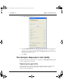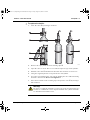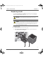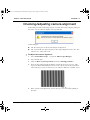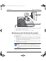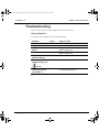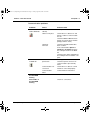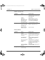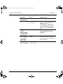
1
Man0411-1.1 (Morphologi G3 Essentials).book Page i Friday, August 29, 2008 10:24 AM Morphologi G3 Essentials MAN0411 Issue 1.1 August 2008 English Man0411-1.1 (Morphologi G3 Essentials).book Page ii Friday, August 29, 2008 10:24 AM © Malvern Instruments Ltd. 2008 Malvern® Instruments makes every effort to ensure that this document is correct. However, due to Malvern Instruments’ policy of continual product development we are unable to guarantee the accuracy of this, or any other document after the date of publication. We therefore disclaim all liability for any changes, errors or omissions after the date of publication. No reproduction or transmission of any part of this publication is allowed without the express written permission of Malvern Instruments Ltd. Head office: Malvern Instruments Ltd. Enigma Business Park, Grovewood Road, Malvern, Worcestershire WR14 1XZ United Kingdom. Tel + [44] (0)1684-892456 Fax + [44] (0)1684-892789 Morphologi is a registered trademark in the UK and /or other countries, and is owned by Malvern Instruments Ltd. Malvern and the green “hills” logo are registered trademarks in the UK and/or other countries, and is owned by Malvern Instruments Ltd. Windows XP is a registered trademark of the Microsoft Corporation. Morphologi G2 and G3 are registered trademarks of Malvern Instruments. Eclipse is a registered trademark of Nikon Corporation. FireWire is a registered trademark of Apple Computer, Inc. Printed in England Man0411-1.1 (Morphologi G3 Essentials).book Page i Friday, August 29, 2008 10:24 AM Table of Contents Introduction to this manual Introduction . . . . . . . . . . . . . . . . . . . . . . . . . . . . . . . . . . . . . . . . . . . . . . 1-1 How to use this manual . . . . . . . . . . . . . . . . . . . . . . . . . . . . . . . . . . . . . 1-1 Access to the instrument . . . . . . . . . . . . . . . . . . . . . . . . . . . . . . . . . . . . 1-2 Assumed information . . . . . . . . . . . . . . . . . . . . . . . . . . . . . . . . . . . . . . . 1-3 Where to get help . . . . . . . . . . . . . . . . . . . . . . . . . . . . . . . . . . . . . . . . . . 1-3 Site requirements Introduction . . . . . . . . . . . . . . . . . . . . . . . . . . . . . . . . . . . . . . . . . . . . . . 2-3 Environmental conditions . . . . . . . . . . . . . . . . . . . . . . . . . . . . . . . . . . . . 2-3 Space required. . . . . . . . . . . . . . . . . . . . . . . . . . . . . . . . . . . . . . . . . . . . 2-4 Air line specification (G3S instruments) . . . . . . . . . . . . . . . . . . . . . . . . . . 2-5 Power requirements . . . . . . . . . . . . . . . . . . . . . . . . . . . . . . . . . . . . . . . . 2-5 Computer specification and usage . . . . . . . . . . . . . . . . . . . . . . . . . . . . . 2-6 Health and Safety General warnings and regulations . . . . . . . . . . . . . . . . . . . . . . . . . . . . . . 3-1 Electrical warnings and regulations . . . . . . . . . . . . . . . . . . . . . . . . . . . . . 3-1 Power cords and Power safety . . . . . . . . . . . . . . . . . . . . . . . . . . . . . . . . 3-3 Sample handling warnings . . . . . . . . . . . . . . . . . . . . . . . . . . . . . . . . . . . 3-5 Basic maintenance Introduction . . . . . . . . . . . . . . . . . . . . . . . . . . . . . . . . . . . . . . . . . . . . . . 4-1 Cleaning the instrument . . . . . . . . . . . . . . . . . . . . . . . . . . . . . . . . . . . . . 4-2 Removing or replacing objectives . . . . . . . . . . . . . . . . . . . . . . . . . . . . . . 4-3 Characterising the instrument . . . . . . . . . . . . . . . . . . . . . . . . . . . . . . . . . 4-3 The Sample Dispersion Unit (G3S) . . . . . . . . . . . . . . . . . . . . . . . . . . . . . . 4-4 Replacing a bulb . . . . . . . . . . . . . . . . . . . . . . . . . . . . . . . . . . . . . . . . . . 4-6 Checking/adjusting camera alignment . . . . . . . . . . . . . . . . . . . . . . . . . . . 4-8 Backing up and Archiving the system . . . . . . . . . . . . . . . . . . . . . . . . . . . 4-9 Troubleshooting . . . . . . . . . . . . . . . . . . . . . . . . . . . . . . . . . . . . . . . . . . 4-11 Morphologi G3 Essentials Page i Man0411-1.1 (Morphologi G3 Essentials).book Page ii Friday, August 29, 2008 10:24 AM Table of Contents Morphologi G3 Installation Introduction . . . . . . . . . . . . . . . . . . . . . . . . . . . . . . . . . . . . . . . . . . . . . . 5-1 Moving the instrument . . . . . . . . . . . . . . . . . . . . . . . . . . . . . . . . . . . . . . 5-2 Upgrading the computer . . . . . . . . . . . . . . . . . . . . . . . . . . . . . . . . . . . . . 5-4 Changing the computer . . . . . . . . . . . . . . . . . . . . . . . . . . . . . . . . . . . . . 5-4 Page ii MAN 0411 Man0411-1.1 (Morphologi G3 Essentials).book Page 1 Friday, August 29, 2008 10:24 AM 1 Introduction to this manual Introduction This manual covers essential information on the Morphologi® G3 particle analyser system. In simple terms this is an automated microscope and a software package for control, measurement and analysis. The instrument measures the size and shape of a sample of particles, presenting the data according to the user’s needs. This manual describes the following essential information: What the site for the Morphologi® G3 requires. All health and safety issues – all users must read this. User maintenance and troubleshooting procedures. User installation procedures – how to move the instrument between rooms, if required, and how to upgrade the software. How to use this manual Users must read the Health and Safety information in Chapter 3 before operating the instrument. This information applies to the instrument itself, as well as any accessories used as part of the complete system. Read this manual in conjunction with the main Morphologi user manual. Morphologi G3 Essentials Page 1-1 Man0411-1.1 (Morphologi G3 Essentials).book Page 2 Friday, August 29, 2008 10:24 AM 1 Chapter 1 Introduction to this manual Access to the instrument This manual refers to the various people who will have access to the instrument, as follows. Malvern Instruments personnel Malvern® Instruments personnel (service engineers, representatives, etc.) have full access to the instrument and are the only people authorised to perform all service procedures that may require the removal of the covers. Warning! Removal of the covers by unauthorised personnel will invalidate the warranty of the instrument. Supervisor The supervisor is the person responsible for the management and safety of the instrument and its operation. The supervisor is responsible for the training of the operators. The supervisor can perform all user maintenance routines identified in Chapter 4. Operator An operator is a person trained in the use of the system. The operator can perform all user maintenance routines identified in Chapter 4. Warning! Under no circumstances should the supervisor or an operator remove the main cover of the instrument. Failure to follow these guidelines could result in exposure to hazardous voltages. Page 1-2 MAN 0411 Man0411-1.1 (Morphologi G3 Essentials).book Page 3 Friday, August 29, 2008 10:24 AM Introduction to this manual Chapter 1 Assumed information To make full use of this manual, the user should understand the following points. Naming convention The Morphologi G3 is referred to either in full as the Morphologi G3 or G3S, or as ‘the instrument’. The combination of the Morphologi G3 instrument, the computer and the Morphologi software is referred to as ‘the system’. Menu commands Menu commands from the Morphologi software are always shown in bold text and shown in the form: main menu-menu item-submenu item. For example, the command File-New-SOP refers to selecting the SOP submenu item under New in the File menu. Where to get help This section describes the available sources of information on the system. Manuals The available manuals are: This Essentials manual. The Quickstart manual – walks through use of the system. The main user manual – gives an overview of the system as a whole and the Morphologi software. Online help The software’s online help gives detailed information on the Morphologi software. Each Morphologi software dialogue has a Help button giving information specific to it. Morphologi G3 Essentials Page 1-3 Man0411-1.1 (Morphologi G3 Essentials).book Page 4 Friday, August 29, 2008 10:24 AM Chapter 1 Introduction to this manual Help desk All queries regarding the system should initially be directed to the local Malvern Instruments representative. Please quote the following information: Model and serial number of the instrument (located on the back of the instrument). Quote the Malvern Instruments serial number. The software version (to find this, select the command Help-About Morphologi in the software). Contact the United Kingdom help desk if the local Malvern Instruments representative is not available. Its direct line is +44 (0) 1684 891800. Note This help line is primarily English speaking. Remote support Malvern Instruments offers a remote support service, delivered by an Internet connection. Benefits include fast and efficient fault diagnosis, reducing downtime and costs. On-line user training is also available, plus software updates. A high speed Internet connection is recommended for making use of this facility. Malvern Website - www.Malvern.com The Malvern Instruments website offers a comprehensive range of particle characterisation resources for use by customers 24 hours a day, seven days a week. Resources include software downloads, frequently asked questions, a knowledge base and application notes, plus information on other particle characterisation solutions that Malvern Instruments can provide. Page 1-4 MAN 0411 Man0411-1.1 (Morphologi G3 Essentials).book Page 1 Friday, August 29, 2008 10:24 AM 2 Site requirements Chapter 2 of the Morphologi G3 Essentials Manual MAN 0411 Issue 1.1 Morphologi G3 Essentials Page 2-1 Man0411-1.1 (Morphologi G3 Essentials).book Page 2 Friday, August 29, 2008 10:24 AM 2 © Malvern Instruments Ltd. 2008 Malvern® Instruments makes every effort to ensure that this document is correct. However, due to Malvern Instruments’ policy of continual product development we are unable to guarantee the accuracy of this, or any other document after the date of publication. We therefore disclaim all liability for any changes, errors or omissions after the date of publication. No reproduction or transmission of any part of this publication is allowed without the express written permission of Malvern Instruments Ltd. Head office: Malvern Instruments Ltd. Enigma Business Park, Grovewood Road, Malvern, Worcestershire WR14 1XZ United Kingdom. Tel + [44] (0)1684-892456 Fax + [44] (0)1684-892789 Morphologi is a registered trademark in the UK and /or other countries, and is owned by Malvern Instruments Ltd. Malvern and the green “hills” logo are registered trademarks in the UK and/or other countries, and is owned by Malvern Instruments Ltd. Windows XP is a registered trademark of the Microsoft Corporation. Morphologi G2 and G3 are registered trademarks of Malvern Instruments. Eclipse is a registered trademark of Nikon Corporation. FireWire is a registered trademark of Apple Computer, Inc. Printed in England Man0411-1.1 (Morphologi G3 Essentials).book Page 3 Friday, August 29, 2008 10:24 AM Site requirements Chapter 2 Introduction This document outlines all site requirements needed to install a Morphologi G3 system. Ensure that all site requirements are fulfilled before the Malvern Instruments engineer arrives to install and commission your system. Environmental conditions When choosing a site for the system, ensure that the following environmental conditions are satisfied: The Morphologi G3 system and any accompanying accessories are intended for indoor use only. Always position the system away from strong light sources, for example windows allowing in bright sunlight. Position the optical unit away from strong heat sources (e.g. radiators). The bench that carries the system must be horizontal and vibration free. It must also be capable of supporting the weight of the system. This table lists the weights of the system components: Component Weight Morphologi G3 (with stage) Approx. 60kg Computer and Printer See manufacturer’s documentation Avoid passing electrical cables through areas where liquids can be spilt. Rooms must be well ventilated if noxious samples or dispersants are used. It is recommended that the computer is positioned to the right of the instrument. Warning! Do not position the system so power sockets are obstructed. They may need to be disconnected during an emergency. Morphologi G3 Essentials Page 2-3 Man0411-1.1 (Morphologi G3 Essentials).book Page 4 Friday, August 29, 2008 10:24 AM Chapter 2 Site requirements The system is designed to be stored and operated in the following conditions: Operating temperature +10 to +35°C (+50 to 95°F) Storage temperature -20 to +50°C (-104 to +122°F) Humidity 10 to 90% (non-condensing) Altitude Up to 2000m Pollution degree 2 Mains supply voltage fluctuations ±10% of nominal voltage Storage Store the microscope in a dry place where no mould will form. Store objectives and eyepieces in a dessicator or similar container with a drying agent. Put the vinyl cover over the microscope to protect it from dust. (Before covering it, power off the microscope and allow it to cool.) Space required Provide enough space to allow easy access to all components of the system. Allow 2500mm (width) x 850mm (depth) of bench space. The instrument footprint depth is 760mm. Allow at least 800mm above the bench surface for access to the cell area. Dimensions of the main components of the system are given below. Page 2-4 Component Width Depth Height Morphologi G3 440mm 760mm 700mm Computer and printer See manufacturer’s documentation MAN 0411 Man0411-1.1 (Morphologi G3 Essentials).book Page 5 Friday, August 29, 2008 10:24 AM Site requirements Chapter 2 Air line specification (G3S instruments) If a Morphologi G3S instrument is supplied - one with an integral Sample Dispersion Unit (SDU) - then the following air line specification must be met. Caution! The air line supply must be dry, free from oil and filtered to less than 0.01mm. Failure to meet this specification will permanently damage the dispersion unit and invalidate the warranty. Air line pressure 5.5 to 9 bar g, but should nominally be set to 6 bar g. Air flow At least 90 l/min at 6 bar (87 psi g). Air line oil filtering To Class 1 of ISO 8573.1. i.e. <0.003mg/m3. Air line particulate filtering To class 1 i.e. <0.01mm. The outlet from the compressor must be fitted with a push-fit adapter capable of taking a 6mm (outside diameter) polyurethane pneumatic tube. Sound emissions from the system (including the compressor) must be less than 85 dBA, (measured at the operator’s position). Power requirements The mains power supply must be clean and filtered. If necessary, fit an Uninterruptible Power Supply (UPS) to remove any spikes or noise. The power requirement for each component of the Morphologi G3 system is given below. Component Power requirement Power sockets required Morphologi G3 ~ 100-240V, 50-60Hz 1 Electronics controls PSU ~ 100-240V, 50-60Hz 1 Computer See manufacturer’s documentation 1 Computer monitors See manufacturer’s documentation 2 Morphologi G3 Essentials Page 2-5 Man0411-1.1 (Morphologi G3 Essentials).book Page 6 Friday, August 29, 2008 10:24 AM Chapter 2 Site requirements Computer specification and usage Contact the Malvern Helpdesk or website for the recommended computer specification; otherwise consult the Software Update Notification document supplied on the software CD. The Morphologi software can be run on a network but this is not recommended as running other software at the same time may reduce the speed of the Morphologi software. Page 2-6 MAN 0411 Man0411-1.1 (Morphologi G3 Essentials).book Page 1 Friday, August 29, 2008 10:24 AM 3 Health and Safety General warnings and regulations Warning! The instrument or the samples to be measured may be hazardous if misused. Read and fully understand this section before operating the system. The instrument must only be stored or operated in environmental conditions conforming to the specification in Chapter 2, Site requirements. Warning! Use of the system in a manner not specified by Malvern Instruments Ltd. may impair the protection provided by the system. Electrical warnings and regulations Warning! The Morphologi G3 System contains high voltage components. Unless advised within the content of this manual, only Malvern Instruments trained personnel are permitted to remove the main cover of any part. Warning! This product must be connected to a protective earth. The metal parts of the optical unit are earthed using a protective earth connection. Morphologi G3 Essentials Page 3-1 Man0411-1.1 (Morphologi G3 Essentials).book Page 2 Friday, August 29, 2008 10:24 AM 3 Chapter 3 Health and Safety If the instrument gets wet (for example, if sample or dispersant is spilt), switch it off and disconnect it from the mains power supply immediately. Carefully clean and dry the instrument before re-applying power. The Morphologi G3 system components are mains powered devices and all power cables and electrical sockets should be treated accordingly. Do not place cables in positions where they are likely to become wet. Hot components Warning! The lamp and the back of the microscope become very hot. Power the instrument off and wait 30 minutes before touching either of these. Do not place fabric, paper or flammable materials anywhere in this area. This high temperature label marks those components which will become hot during use. These are the lamp houses. Crush hazard Warning! Keep hands out of the stage area when the stage is moving – fingers can be caught between the stage and parts of the microscope. When the user initialises the stage it may start to move back to a preset position. Keep hands clear when initialising. Page 3-2 MAN 0411 Man0411-1.1 (Morphologi G3 Essentials).book Page 3 Friday, August 29, 2008 10:24 AM Health and Safety Chapter 3 Power cords and Power safety The notes in this section indicate best practice and should be adhered to when connecting the Malvern instrument to the power supply. Power cord set requirements Power cord sets must meet the requirements of the country where the product is used. For further information on power cord set requirements, contact a Malvern Instruments representative. General requirements The requirements listed below are applicable to all countries: The power cord must be approved by an acceptable accredited agency responsible for evaluation in the country where the power cord set will be installed. The power cord set must have a minimum current capacity of 10A (7A in Japan only) and a nominal voltage rating of 125 or 250 volts AC, as required by each country's power system. The area of the wire must be a minimum of 0.75mm2 or 18AWG, and the length of the cord must be less than 3m. The power cord must be routed so it is not likely to be walked on or pinched by items placed upon it or against it, or become wet. Particular attention must be paid to the plug, the electrical outlet, and the point where the cord exits the product. Warning! Do not operate this product with a damaged power cord set. If the power cord set is damaged in any manner, replace it immediately. Warning! Do not use the power cord received with this product on any other products. Power safety information The following notes indicate guidelines to follow when connecting the Malvern Instruments power supply using single and multiple extension leads, connection via AC Adapters and use of Uninterruptible Power Supplies (UPS). Morphologi G3 Essentials Page 3-3 Man0411-1.1 (Morphologi G3 Essentials).book Page 4 Friday, August 29, 2008 10:24 AM Chapter 3 Health and Safety Warning! To prevent electric shock, plug the instrument or accessory into correctly earthed electrical outlets. The power cord supplied is equipped with a grounding connection to ensure grounding integrity is maintained. Advice on use of Extension leads Follow this advice when using single or multiple socket extension leads. These are also called trailing sockets. Ensure the lead is connected to a wall power outlet and not to another extension lead. The extension lead must be designed for grounding plugs and plugged into a grounded wall outlet. Ensure that the total ampere rating of the products being plugged into the extension lead does not exceed the ampere rating of the extension lead. Use caution when plugging a power cord into a multiple socket extension lead. Some extension leads may allow a plug to be inserted incorrectly. Incorrect insertion of the power plug could result in permanent damage to the instrument or accessory, as well as risk of electric shock and/or fire. Ensure that the ground connection (prong/pin) of the power cord plug is inserted into the mating ground contact of the extension lead Advice on use of AC adapters Warning! Do not use adapter plugs that bypass the grounding feature, or remove the grounding feature from the plug or adapter. Place the AC adapter in a ventilated area, such as a desk top or on the floor. The AC adapter may become hot during normal operation of the instrument or accessory. Use care when handling the adapter during or immediately after operation. Use only the Malvern-provided AC adapter approved for use with the instrument and/or accessory. Use of another AC adapter may cause a fire or explosion. Advice on use of Uninterruptible Power Supplies (UPS) To help protect the instrument and/or accessory from sudden, transient increases and decreases in electrical power, use a surge suppressor, line conditioner or UPS. Page 3-4 MAN 0411 Man0411-1.1 (Morphologi G3 Essentials).book Page 5 Friday, August 29, 2008 10:24 AM Health and Safety Chapter 3 Sample handling warnings Always handle all substances in accordance with the COSHH (Control Of Substances Hazardous to Health) regulations (UK) or any local regulations concerning sample handling safety. Before using any substance, check the Material Safety Data Sheets for safe handling information. Use the instrument in a well ventilated room, or preferably within a fume cupboard, if the fumes from the sample or dispersant are toxic or noxious. Wear personal protective equipment as recommended by the Material Safety Data Sheets if toxic or hazardous samples are being handled, particularly during sample preparation and measurement. Wear protective gloves when handling hazardous materials, or those that cause skin infections or irritations. Do not smoke during measurement procedures, particularly where inflammable samples are used or stored. Do not eat or drink during measurement procedures, particularly where hazardous samples are used or stored. Take care when handling glass (e.g. microscope slides and beakers). Hazardous materials may enter a wound caused by broken glass. Always test a new sample or dispersant for chemical compatibility before use. After measuring hazardous samples, scrupulously clean the system to remove any contaminants before making another measurement. Always label samples for analysis using industry standard labelling, particularly if they are handled by a number of staff or stored for long periods. Clearly mark any operator hazard and associated safety precautions that are required for the handling of dangerous materials. Keep a record of all hazardous substances used in the system for protection of service and maintenance personnel. Always adopt responsible procedures for the disposal of waste samples. Most local laws forbid the disposal of many chemicals in such a manner as to allow their entry into the water system. The user is advised to seek local advice as to the means available for disposal of chemical wastes in the area of use. Refer to the Materials Safety Data Sheets. The surfaces of the system may be permanently damaged if samples are spilt on them. If a spillage does occur, disconnect the system from the power supply before scrupulously cleaning up the spillage. Morphologi G3 Essentials Page 3-5 Man0411-1.1 (Morphologi G3 Essentials).book Page 6 Friday, August 29, 2008 10:24 AM Chapter 3 Health and Safety Moving the system If it is necessary to move the system, follow the guidelines given in Chapter 5 Installation. Warning! Use proper lifting techniques and at least two people to avoid back injury. Always lift the instrument by holding it under its base. Never lift an instrument by precision parts such as the optics, camera or stage, or by its covers. Refer to the handling procedures and diagrams in Appendix B of the main user manual (Unpacking instructions). Disposing of the instrument and accessories When the need eventually arises to dispose of the system, this should be done in a responsible manner. Follow these guidelines: Refer to any local regulations on disposal of equipment; in Europe refer to the information below. Seek advice from the local Malvern Instruments representative for details. Decontaminate the instrument if hazardous materials have been used in it. Disposal of Electrical & Electronic Equipment The following is applicable in the European Union and other European countries with separate collection systems. This symbol on the product or on its packaging indicates that when the last user wishes to discard this product it must not be treated as general waste. Instead it shall be handed over to the appropriate facility for the recovery and recycling of electrical and electronic equipment. By not discarding this product along with other household-type waste, the volume of waste sent to incinerators or landfills will be reduced and natural resources will be conserved. For more detailed information about recycling of this product, please contact your local city office, your waste disposal service, or your Malvern Instruments representative. ill 7610 Page 3-6 MAN 0411 Man0411-1.1 (Morphologi G3 Essentials).book Page 1 Friday, August 29, 2008 10:24 AM 4 Basic maintenance Introduction The instrument is designed to minimise supervisor/operator maintenance. This chapter explains the routine user maintenance procedures that can be performed. These procedures are: Cleaning the instrument (including the objectives). The Sample Dispersion Unit (SDU). Removing or replacing objectives. Characterising the instrument. Replacing a bulb. Checking/adjusting camera alignment. Backing up and archiving the system. Troubleshooting - hardware troubleshooting information. Warning! Nobody except a qualified Malvern representative should remove the main cover of any component. Morphologi G3 Essentials Page 4-1 Man0411-1.1 (Morphologi G3 Essentials).book Page 2 Friday, August 29, 2008 10:24 AM 4 Chapter 4 Basic maintenance Cleaning the instrument Cover the instrument with its dust cover when it’s not used for long periods. Caution! The surfaces of the instrument may be permanently damaged if samples or dispersants are spilt on them. If a spillage occurs disconnect the system from the power supply before carefully cleaning it up. Warning! Always ensure that the instrument is disconnected from the power supply and all electrical cables are disconnected. Thoroughly clean all the following: The covers – periodically, using a mild soap solution and silicon cloth. The paint has a solvent resistant finish, but it is good practice never to use a solvent based solution as this may result in damage to the painted surfaces. The condensing lens – when dust has gathered use a compressed air aerosol first. If this is not sufficient, use a lint free cloth and isopropyl alcohol. Wipe with a rolling motion so no particles of dirt are dragged across the lens surface. The objectives – remove dust with compressed air or a soft brush. or by wiping gently with gauze. If there are fingerprints or grease on an objective lens, use alcohol (ethyl or methyl) to dampen a piece of soft cloth, lens tissue or gauze and wipe the lens very gently. Gratings and sample plates – periodically with a suitable mild soap solution. Guidelines Page 4-2 Never use excessive liquid to clean the instrument and always avoid electrical components (connectors, etc.). Always ensure the instrument is completely dry before applying power. Do not touch the objectives or condensing lens during cleaning. If using alcohol to remove grease or fingerprints, be careful when handling it. It is flammable so keep away it from power switches, etc. Never use an abrasive cleaner to clean the instrument as this may result in damage to the painted surfaces. Do not use compressed air, apart from on the condensing lens. MAN 0411 Man0411-1.1 (Morphologi G3 Essentials).book Page 3 Friday, August 29, 2008 10:24 AM Basic maintenance Chapter 4 Removing or replacing objectives The objectives must be replaced in their correct positions; the software is by default set up for the objective fittings shown below. The first Position column shows the setup when the 1X option is fitted, the second Position column shows the situation when the option is absent. The text after the objective name in the table is that which appears on the objective itself. Objective fitted Position (1x fitted) Position (1x absent) 1X option (if fitted) 1 2.5X / 0.075 (25 to 32mm adaptor used) 2 1 5X / 0.15 (A) 3 2 10X / 0.30 (A) 4 3 20X / 0.40 (A) 5 4 50X / 0.55 (A) 6 5 If it is ever necessary to change an objective position, contact Malvern Instruments. Characterising the instrument Characterisation is required after: Removing an objective, especially if it’s 10X or above, for cleaning. Adding one or more new objectives. Moving the instrument any distance, even between laboratories at a site. To characterise the instrument: 1. Run the command Tools-Maintenance mode. This displays a dialogue asking for the maintenance password, which Malvern Instruments should have supplied. 2. Type in the password. If it is correct, the following message box is displayed: 3. Close the message box then run the command Tools-Characterise Instrument, which will have replaced Maintenance mode as the only sub-option of Tools-Maintenance. Morphologi G3 Essentials Page 4-3 Man0411-1.1 (Morphologi G3 Essentials).book Page 4 Friday, August 29, 2008 10:24 AM Chapter 4 Basic maintenance 4. The Set up microscope dialogue appears: 5. Press the Characterise button. This runs through the full process. There’s no need for a user to press the separate Start buttons. (However, if an objective’s just been unscrewed then retightened, clicking Start button 4 will save time by skipping the first three steps.) 6. Click OK. The Sample Dispersion Unit (G3S) Replacement foil rings and gas bottles are available from www.Malvernstore.com or the local Malvern representative. Replacing the gas bottle The gas bottle is for use in labs without an air supply. It will need replacing after about 650 dispersions; the pressure regulator will show when it’s empty. Order part number MOR4107. Page 4-4 MAN 0411 Man0411-1.1 (Morphologi G3 Essentials).book Page 5 Friday, August 29, 2008 10:24 AM Basic maintenance Chapter 4 To replace the bottle: Close the valve ! by turning it clockwise. 1. A E C D B B ill 8142 2. Remove the empty bottle from its retaining clips ". 3. Open the valve to ensure there is no residual compressed gas in the cylinder. 4. Hold the valve unit # still and turn the bottle anti-clockwise to unscrew it. 5. Using the supplied puncture tool, puncture the old cylinder. 6. Screw the new bottle into the valve unit by holding the valve still and turning the bottle clockwise $. Do not overtighten it. 7. Insert the new bottle in the retaining clips and open the valve % by turning it anti-clockwise. Warning! Do not try to refill the old bottle. Contact your local environmental representative to establish the correct disposal method. The cylinder materials are aluminium and stainless steel. Morphologi G3 Essentials Page 4-5 Man0411-1.1 (Morphologi G3 Essentials).book Page 6 Friday, August 29, 2008 10:24 AM Chapter 4 Basic maintenance Cleaning the dispersion chamber Clean the dispersion chamber after each dispersion and especially when switching between samples of different types. Wipe lightly with an alcohol-based cleaner, using a lint-free cloth, then use a compressed air spray. Page 4-6 MAN 0411 Man0411-1.1 (Morphologi G3 Essentials).book Page 7 Friday, August 29, 2008 10:24 AM Basic maintenance Chapter 4 Replacing a bulb The replacement bulb must be a PHILIPS 7724 halogen lamp (12V 100W long life). The nominal bulb life is 1500 hours. Malvern Instruments supplies packs of five bulbs; the order code is MOR4002. Warning! Do not power on the instrument on while the lamp cover is open! Caution! Hold the new bulb with gloves or a clean cloth, not bare hands. Do not touch the glass lamp surface with bare hands; fingerprints or grease will reduce the illumination capacity of the lamp. Wipe any fingerprints or grease off with a clean piece of cloth. To replace a bulb: 1. Power off the instrument at the mains switch. 2. Wait 30 minutes before touching the lamp house or the back of the microscope; they become hot during use! 2 1 ill 8129 Morphologi G3 Essentials Page 4-7 Man0411-1.1 (Morphologi G3 Essentials).book Page 8 Friday, August 29, 2008 10:24 AM Chapter 4 Page 4-8 Basic maintenance 3. Carefully ease the lamp house out. 4. Loosen the clamp screw as shown below with a coin and remove the lamp house cover. 5. Press down the lamp clamp lever and remove the old bulb. 6. Press down the lever again and, without touching the new bulb with the fingers, push the new bulb into the socket. 7. Without tilting the bulb, slowly return the lamp clamp lever to its original position. 8. Close the lamp house securely and tighten its clamp screw . 9. Gently push the lamp house into place, making sure that the two prongs slide into the holes in the back of the microscope unit. MAN 0411 Man0411-1.1 (Morphologi G3 Essentials).book Page 9 Friday, August 29, 2008 10:24 AM Basic maintenance Chapter 4 Checking/adjusting camera alignment Follow this procedure if the image appears “twisted” when inspecting the grating. If this is the case the software displays a message like this: In this dialogue: The first value given is the measured angle of alignment. The second value (in square brackets) is the target alignment. This is 90°. The tolerance is 1° either side of 90. To adjust the camera alignment: 1. Select Tools-Microscope… to open the Microscope Manager. 2. Select the 5X optic. 3. Click on Move to preset position and choose Grating position 3. 4. Focus on the grating and check that the camera tilt does not exceed 1°. This represents about 5mm difference between the edge of a bar at the top and bottom of the large screen (see below). Try to achieve a difference of 2mm or less. 5. If the camera needs adjustment, remove the top cover turret ! by pulling it upwards. Morphologi G3 Essentials Page 4-9 Man0411-1.1 (Morphologi G3 Essentials).book Page 10 Friday, August 29, 2008 10:24 AM Chapter 4 Basic maintenance A B ill 8128 6. Use a 2mm Allen key to slacken the adjustment screw " and rotate the camera until the grating is within the tolerance. 7. When adjustment is complete, tighten the screw up again. Backing up and Archiving the system We recommend that files are copied/moved from the computer regularly as part of two similar processes: Backing up – the regular process of copying data to a server or other media as insurance against computer disk failure, other hardware problems, or problems in the laboratory. This should be undertaken at a frequency, probably weekly or monthly, in line with company procedures. Archiving – the process of moving older data from the computer, for example when the disk becomes nearly full. Note Image files, stored as .img files in the folder Particle Data, are numerous and take up a lot of space. When copied from the control computer, we recommend that before storage these are compressed using a tool such as Winzip. Follow the procedures described below. Page 4-10 MAN 0411 Man0411-1.1 (Morphologi G3 Essentials).book Page 11 Friday, August 29, 2008 10:24 AM Basic maintenance Chapter 4 Backups To allow recovery of the full system, make copies of the following (assuming that the software is installed on the C: drive): The entire contents (all sub-folders) of the folder: C:\Documents and Settings\All Users\Shared Documents\Malvern Instruments\Morphologi From the following folder, the files PlateDetails.CFG, SiteSettings.CFG and any files with the suffix .wrkspace. C:\Documents and Settings\All Users\Application Data\Malvern Instruments\Morphologi To restore the files, simply copy them back to their respective locations. Note Some files may be “hidden”. To view these in the Microsoft Windows™ folder display, click Tools-Folder options then select the View tab and change the Hidden files and folders settings. Archives For archiving of older information: If the distribution data are sufficient and the individual image files are not required (this will save significant amounts of space in the archive but will not permit re-analysis of the data in future), save the contents of all sub-folders of the following folder, except for Particle Data: C:\Documents and Settings\All Users\Shared Documents\Malvern Instruments\Morphologi If all the measurement data including the individual image files are required, save the contents of all sub-folders of the following folder. (This will allow completely new analysis of the data in future if required.) C:\Documents and Settings\All Users\Shared Documents\Malvern Instruments\Morphologi To restore the files, simply copy them back to their respective locations. Morphologi G3 Essentials Page 4-11 Man0411-1.1 (Morphologi G3 Essentials).book Page 12 Friday, August 29, 2008 10:24 AM Chapter 4 Basic maintenance Troubleshooting This section describes possible problems and how to fix them. General problems To diagnose these problems, look at the LED panel. Problem Cause Action to take PWR LED on only Check 40V PSU connected OK. +5V, 12V LED off Check 5A fuse in control module. PWR, +5V, 12V, AUX Run lit Power on/off. If this fails to fix it, contact Malvern Instruments. XYZ Run not lit. Power on/off. If this fails to fix it, contact Malvern Instruments. Green LEDs on but AUX Run flashing Check PC connections. Green LEDs on but AUX Run flashing and Check PC connections. shown Stage does not respond to joystick, green LEDs on Page 4-12 Check whether XYZ Run is lit. If not, contact Malvern Instruments. MAN 0411 Man0411-1.1 (Morphologi G3 Essentials).book Page 13 Friday, August 29, 2008 10:24 AM Basic maintenance Chapter 4 Communication problems Problem Cause Action to take ‘Connected’ icon is stuck as: Power off (POWER LED off) Check power cable and switch. Cables not in place Check RS232-1 cable to PC and RS232-2 cable to control module are OK. Check the RX and TX LEDs flash during connection (when the Morphologi software starts). COM Port mismatch Check that the Rx and Tx LEDs flash as above. If not select Tools > Options > Hardware > Computer and note the COM port shown in the Port: list. Check that the cable is plugged into this COM port then restart the computer. ‘Connected’ icon is stuck as: Control module not powered on Check green LED on 40V PSU is lit. Control module not connected Check RS232-2 cable on control module is connected properly. Control module failed Contact Malvern Instruments. Check that power connector on control module is pressed fully home. Green LEDs on but AUX RUN flashing Check PC connections. Green LEDs on but AUX RUN flashing Check PC connections. Morphologi G3 Essentials Page 4-13 Man0411-1.1 (Morphologi G3 Essentials).book Page 14 Friday, August 29, 2008 10:24 AM Chapter 4 Basic maintenance Problems with the lamp Problem Cause Lamp not on No power. Action to take Check the power cord. Check microscope is turned on (see green PWR LED). No bulb Install a bulb. Bulb blown Replace the bulb (see above). Episcopic/Diascopic illumination switch not set correctly Reset the switch using the software’s Microscope Manager. Wrong bulb installed Use specified bulb (see above). Bulb about to blow Replace the bulb (see above). Power cord or bulb housing not connected securely Make the component secure. Bulb not inserted in socket securely Reinsert the bulb. Problem Cause Action to take No image Firewire cable problem Check cable connected and camera LED (at rear of camera) is on. Objective nosepiece misaligned Move the nosepiece by hand until it positively locates in a head position. Lamp bulb blown/ poor connection Examine lamphouse, temporarily swap with other lamphouse to prove fault. Microscope switched off or PSU/fuse problem Check T5.0A fuse in control module. This fuse is user-replaceable Camera is looking at black image (camera at home) Move stage to light calibration position and re-check. Sample holder not secure on stage Check the sample holder fitting. Lamp flickers Display problems Image partly dim Page 4-14 If main microscope fuse blows contact Malvern. This is not userreplaceable. MAN 0411 Man0411-1.1 (Morphologi G3 Essentials).book Page 15 Friday, August 29, 2008 10:24 AM Basic maintenance Chapter 4 Problem Cause Action to take Image moves when focused Plate tilted Mount the plate correctly. Image wobbles Display refresh rate set too high Right-click on the computer’s desktop and select Properties in the displayed menu. Click Settings then Advanced. Select the Monitor tab and select the next lowest screen refresh rate. Image misaligned (this can cause double counting of particles) Camera misaligned Follow the above procedure on Checking/adjusting camera alignment. Error message: ”The software was unable to activate the video source” Firewire cable problem Check cable connected and camera LED (on back of camera) is on. Sample does not move smoothly Sample holder not secure on stage Morphologi G3 Essentials If this does not work contact Malvern Instruments. Check the sample holder. Page 4-15 Man0411-1.1 (Morphologi G3 Essentials).book Page 16 Friday, August 29, 2008 10:24 AM Chapter 4 Basic maintenance Dirt or marks on optics Move the optical components in the following order to identify the offending part: 1. Rotate the camera only. If the mark does not move on the image, it is on the camera CCD. If it does move it is on one of the other elements. Proceed as below noting which element moves with the dark dot. Realign afterwards as described in the earlier section Checking/Readjusting camera alignment. 2. Rotate the black tube which holds the digital camera while holding the camera steady. There is a lens in the base of this tube which may have become marked. If the marks rotate they must be on this lens. To clean this lens, remove the camera from the top of the tube. Loosen the grub screw at the base of the camera tube and remove the tube. The lens can now be seen from below. Clean it as described earlier. After cleaning, re-check the camera alignment by focusing on the grating. See the above section on Checking/adjusting camera alignment. 3. Move the BF/DF Bright Field/Dark Field lever in and out. 4. Unscrew the objective a little or try another objective. (After a unscrewing a high magnification objective, especially the 50X, characterisation will probably be required.) 5. Unscrew the black ring holding the condenser assembly (there are three lenses in the condenser assembly). Rotate the assembly. If this does not identify the problem contact Malvern Instruments. Page 4-16 MAN 0411 Man0411-1.1 (Morphologi G3 Essentials).book Page 1 Friday, August 29, 2008 10:24 AM 5 Installation Introduction The Morphologi G3 system should initially be commissioned by Malvern trained personnel. This appendix shows how to re-install the system, typically required under the following circumstances: Moving the instrument If the system has to be moved from one laboratory to another, read the information in this appendix to reconnect the system correctly. Upgrading the computer It may be company policy to upgrade computers periodically. Detail is given on the actions required. If required to change the computer, contact Malvern Instruments. Only install the system in a suitable environment as detailed in Environmental conditions in Chapter 2. Morphologi G3 Essentials Page 5-1 Man0411-1.1 (Morphologi G3 Essentials).book Page 2 Friday, August 29, 2008 10:24 AM 5 Chapter 5 Installation Moving the instrument Handle the instrument carefully. Do not subject it to any strong physical shock. Warning! Use proper lifting techniques and at least two people to avoid back injury. Always lift the instrument by holding it under its base. Never lift an instrument by precision parts such as the optics, camera or stage, or by its covers. Refer to the handling procedures and diagrams in Appendix B of the main user manual (Unpacking instructions). Note If the original setup was performed as part of an IQ/OQ, moving the system invalidates this. Short distance movements If moving the system just within a room: Power off all components. Disconnect the mains power cable from the Morphologi G3. The system can be moved with all cables still connected to it, so long as this is done with care. These cables must be disconnected at their far end, that is at the computer. Move the computer equipment according to the supplier’s instructions. At the new location, reverse the above procedure then characterise the instrument. Caution! During reassembly take care not to scratch or touch the lens surfaces. Longer distance movements If moving the system a significant distance, either across a site or further: Page 5-2 1. Power off all components. 2. Turn off the air supply then disconnect the air connection. MAN 0411 Man0411-1.1 (Morphologi G3 Essentials).book Page 3 Friday, August 29, 2008 10:24 AM Installation Chapter 5 3. Remove the SDU, lamp houses, gas bottle and objectives. 4. Remove the base cover (fixed with two screws and two clips). 5. Remove the Z control motor and its cable from the left side of the stage. 6. If shipping the system a significant distance, not just within a site, remove the stage. Remove the four mounting bolts and carefully lift out the stage. Otherwise, use the coarse focus control to lower the stage gently to its resting position. 7. Remove the other covers. The camera turret just pulls off, the rear cover is held by four screws and the front/top cover is held by clips only. 8. Remove the camera and tube together and do not separate these (to prevent dust ingress from the top of the instrument). 9. Remove the camera cable, power cable, RS-232 cable and joystick cable from the computer. 10. Disconnect the mains power cable from the Morphologi G3. 11. Pack all components, if possible in their original packaging. 12. Disconnect and pack the computer and monitors, following the manufacturer’s instructions. 13. At the new location, reverse the above procedure. Caution! During reassembly take care not to scratch or touch the lens surfaces. Warning! This product must be connected to a protective earth. 14. 15. Set up the following computer connections: COM port – to the connection labelled RS232-1 on the back panel. FireWire port – to the FireWire port on the digital camera. Recharacterise the objectives. Morphologi G3 Essentials Page 5-3 Man0411-1.1 (Morphologi G3 Essentials).book Page 4 Friday, August 29, 2008 10:24 AM Chapter 5 Installation Upgrading the computer If an upgrade CD is provided, follow this procedure. Note If the original software is subsequently updated with a new version, any custom reports, parameter settings, SOPs, etc. will be preserved. We recommend backing up this data first, though. To upgrade the software: 1. Remove the old version of the software using the Add/Remove Programs function in the Windows Control Panel. 2. Insert the new Morphologi G3 CD in the CD drive. 3. If Autorun is enabled on the computer, the software will start to install automatically. Follow all on-screen instructions to complete the installation. 4. If Autorun is not enabled, select Start-Run-Setup.exe and follow the onscreen instructions. Changing the computer If the computer to be used with the instrument has to be changed, contact Malvern Instruments. Page 5-4 Morphologi G3 Essentials Man0411-1.1 (Morphologi G3 Essentials).book Page i Friday, August 29, 2008 10:24 AM Index A I AC adapter safety 3-4 Access to the instrument 1-2 Air line specification 2-5 Image dim (problem) 4-13 misaligned 4-14 moving (problem) 4-14 B Bulb replacing 4-6 specification 4-6 C Cable safety 3-3 Camera correcting alignment 4-8 Characterising the instrument 4-3 Cleaning 4-2 Communication problems 4-12 Computer changing 5-4 Cord set safety 3-3 D Dirt/marks on optics 4-15 E Episcopic/Diascopic switch 4-13 Extension lead safety 3-4 F Firewire cable problem 4-13 Fuse blown 4-13 G L Lamp flickering 4-13 Lamp house removal 4-7 Lamp off (problem) 4-13 Lens cleaning 4-2 M Maintenance 4-1 Malvern personnel 1-2 Menu commands in text 1-3 Model number 1-4 O Objective cleaning 4-2 positioning 4-3 positions 4-3 Operator tasks 1-2 P Power cord safety 3-3 Power safety information 3-3 R Grating cleaning 4-2 Remote support 1-4 Replacing a bulb 4-6 Replacing objectives 4-3 H S Health and Safety 3-1 Help desk 1-4 Safety information 3-1 Sample plate cleaning 4-2 Morphologi G3 Essentials Page i Man0411-1.1 (Morphologi G3 Essentials).book Page ii Friday, August 29, 2008 10:24 AM Index Serial number 1-4 Specification 2-1 Supervisor tasks 1-2 T Tools-Characterise Instrument 4-3 Tools-Maintenance mode 4-3 Troubleshooting 4-11 Page ii Morphologi G3 U Uninterruptible Power Supply (UPS) safety 3-4 Upgrading the computer/software 5-4 W Website 1-4 MAN 0411