1
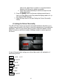
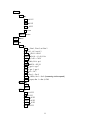
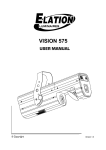
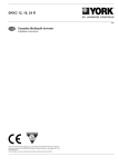
Spot User Manual
V1.0
Garkinhall Systems P.O. Box 449 Franklin, TN 37065
Tel: 615.236.5500 www.garkinhall.com
© Garkinhall Systems, Inc. 2006
All Rights Reserved
The specifications and information supplied in this document are subject to change without notice. Garkinhall Systems,
Inc. assumes no responsibility or liability for any errors or inaccuracies that may appear in this manual.
Printed in the U.S.A.
Important Safety Information
!
Caution: Risk of fire and electrocution. Inappropriate use may result in serious
injury or death.
•
•
•
•
This device should be installed and maintained by qualified personnel
only.
Read all instructions and warnings in this user manual before attempting
to use this device.
Mains power should be properly grounded before energizing.
Replace fuses with proper size and voltage rating only.
Eye Protection
Required
Caution: Risk of ultraviolet (UV) exposure. Looking directly at light source without
protection may cause retina damage. Do not attempt to open fixture housing
without first disconnecting power.
Garkinhall Systems, Inc. accepts no liability for damages resulting from the
failure to read and observe the warnings in this manual, unauthorized
modifications to the device, or the use of the device other than that for which it is
intended.
Trademarks
Trademarks used in this manual are the registered trademarks of Garkinhall Systems, Inc.
2
Table of Contents
Introduction .......................................................................................................... 4
Setting Up ............................................................................................................ 6
A. Unpacking.................................................................................................. 6
B. Checking the Contents .............................................................................. 6
C. Before Applying Power .............................................................................. 6
D. Applying Power.......................................................................................... 8
E. Turning On the Fixture............................................................................... 8
F. Aligning the Lamp...................................................................................... 8
G. Lamp Aligning Procedure .......................................................................... 8
H. Setting the Fixture Personality................................................................. 10
I. Personality Settings................................................................................. 13
J. Setting the DMX512 Address .................................................................. 25
II. Rigging the Fixture ...................................................................................... 26
III.
Cabling the Fixture .................................................................................. 27
A. Data Termination ..................................................................................... 27
IV.
Operating the Fixture............................................................................... 29
A. DMX512 Protocol .................................................................................... 29
V. Troubleshooting the Fixture ........................................................................ 33
A. Power Check ........................................................................................... 33
B. Data Check.............................................................................................. 33
C. Fixture Check .......................................................................................... 33
D. Error Messages ....................................................................................... 34
VI.
Maintenance and Cleaning...................................................................... 37
VII.
Technical Specifications .......................................................................... 38
A. Power supply ........................................................................................... 38
B. Optical System ........................................................................................ 38
C. Electronics ............................................................................................... 38
D. Mechanical .............................................................................................. 39
E. Operation................................................................................................. 39
VIII. Photometric Data..................................................................................... 40
3
Introduction
The GKH 575 Spot from Garkinhall Systems, Inc. is a 575-watt automated profile
luminaire with all the features you expect in a professional fixture.
•
•
•
•
•
•
•
•
Two gobo wheels, one static and one rotating, provide an assortment of
pattern projections from nine static metal gobos plus open, and six rotating
gobos including three metal, one single color and two multi-colored glass
gobos.
Each of the two color wheels has nine dichroic colors plus white including
one CTO, one CTB, and one UV filter.
A multi-step zoom provides beam angles of 15º, 18º, and 22º.
Pan range of 530º, tilt range of 280º.
Other features include a three-facet rotating prism, motorized iris, remote
focus, strobe effects from 1-10 flashes per second, and a dimmer.
The optical train includes a 575-watt MSR lamp and a dichroic glass
faceted reflector for maximum efficiency.
The extensive user-configurable features allow you to set up the fixture to
suit your applications, and the built-in diagnostic features speed
troubleshooting and minimize down time.
Lamp options include: Philips MSR 575/2; Philips MSD 575; or Osram
HSR 575/2.
The GKH 575 Spot is ideally suited for a variety of applications where an
automated profile spot with projection and effects is needed, including houses of
worship, live concerts and events, permanent installations, television and live
event production applications.
With the proper maintenance and upkeep, the GKH 575 Spot luminaire will
provide years of service. This manual is intended as a guide to the proper set up,
operation and care of your fixture. Please read this manual, follow the
recommended procedures and keep it in a safe place for future reference.
4
5
Setting Up
A. Unpacking
Upon receipt of your fixtures, carefully inspect the outside of the packaging and
look for any damage that may have occurred during shipping. Open the package
and carefully inspect its contents for signs of damage. Should there be any
apparent damage, notify the freight company right away. Keep all the packaging
in the event that the freight company dispatches an inspector.
B. Checking the Contents
Included in the packaging are the following items:
1.
2.
3.
4.
5.
6.
(1) GKH 575 Spot luminaire
(1) MSR 575 lamp
(2) Omega rigging brackets with quarter-turn fasteners
(1) safety cable
(1) DMX data cable
(1) User manual
C. Before Applying Power
Once you have made a visual inspection of the packaging and the fixture, you
should set it up and perform a bench test to insure that it is operating correctly.
Before applying power to the unit, make sure to follow these procedures:
1. Check to see that the voltage marked on the packaging matches that of
the power supply. In North America it should be 120V/60Hz.
2. Install the lamp.
a. Insure that the fixture is disconnected from the power source.
Caution: Surface may be extremely hot. Allow several
minutes to cool.
b. Using a Phillips screwdriver, remove the three screws on the back
of the fixture head labeled X, Y, and Z.
6
Caution: Never touch the lamp with your bare hands. The
oil from your hands can cause the quartz envelope of the
lamp to heat up and explode.
c. Without touching the lamp with your bare hands (wear gloves or
use a protective sleeve to hold the lamp), hold the ceramic base of
the lamp and insert it into the lamp socket until it is seated
completely.
d. Replace the lamp and socket assembly in the head of the fixture
and replace the three screws, X, Y and Z.
3. Install the power connector using the following wiring convention:
7
a. Green/yellow – ground
b. Blue – neutral
c. Brown – live or hot
D. Applying Power
Apply power only after the voltage has been confirmed, the lamp installed and
the connector correctly installed.
Warning: Risk of electrical shock.
E. Turning On the Fixture
Connect the fixture to a power source and turn on the red power button located
on the base of the fixture (0=off, 1=on). The fixture will automatically perform a
power-on self test. During the test, the fixture will perform a sequence of
procedures in which each of the functions will be activated, tested and homed.
The self-test will be noisy; this is normal. It will last approximately one minute,
and then the head will return to its home position and the LED display on the
base will display the default DMX512 address (001).
F. Aligning the Lamp
Before operating the fixture for the first time and each time after the lamp is
changed, it is critical that the lamp is correctly re-aligned in the reflector.
!
Caution: Operating the fixture without correctly aligning
the lamp in the reflector may cause damage to internal
components. Always align the lamp before operating for
the first time and each time after changing the lamp.
G. Lamp Aligning Procedure
To align the lamp, find a location with a long, clear sight line to a white wall.
Place the fixture on the floor or on a work bench and perform the following lamp
alignment procedure:
1. Turn on the fixture.
2. After it finishes the power-on self-test, the lamp should be on and
the yoke should be in the default position (pointing straight up if the
fixture is sitting on the ground or pointing straight down if the fixture
8
is hanging from a pipe or truss). You should be able to see a small
amount of light leak from the back of the fixture head. If the lamp is
on, skip to step 7.
3. Strike the Lamp:
a. Using the menu display function, press the [UP] or [DOWN]
button on the LED menu display several times until it reads
LAMP.
b. Press the [ENTER] button.
c. Press the [UP] or [DOWN] button until the display reads ON.
d. Press the [ENTER] button. The lamp should turn on.
NOTE: It takes approximately five minutes for the lamp to
reach its full operating temperature.
e. Press the [MODE] button to back out of the LAMP function.
4. Adjust the dimmer to full and focus the pan and tilt using the menu
display Adjust function:
a. Press the [UP] or [DOWN] button on the LED menu display
several times until the display says SPEC.
b. Press the [ENTER] button.
c. Press the [UP] or [DOWN] button several times until the
display says AdJ.
d. Press the [ENTER] button.
e. Press the [UP] or [DOWN] button several times until the
display says dinr (dimmer).
f. Press the [ENTER] button.
g. Press and hold the [UP] button until the display reaches the
number 255. If you pass it, press the [DOWN] button until it
stops at 255. The light should fade up as the dimmer opens.
h. Press the [ENTER] button.
i. Press the [UP] or [DOWN] button several times until the
display reads TILT.
j. Press the [ENTER] button.
k. Press and hold the [UP] or [DOWN] button until the fixture
head is focused on a white wall. (Rotate the fixture if
necessary or go to the PAN function and adjust the value
until it is correctly focused.)
5. Using the three lamp adjustment screws (labeled A, B, and C) in
the rear of the fixture head, adjust the lamp so that it is centered
correctly in the X, Y, and Z planes of the reflector (side-to-side and
in and out).
a. Using a 4mm (5/32”) hex wrench, turn the three screws
clockwise one revolution one at a time. Observe the spot on
the wall while adjusting the bolts.
b. If the spot appears brighter as you turn each screw, keep
adjusting them in rotation until it no longer has an
intensifying effect. If the spot appear dimmer as you turn
9
each screw, adjust them in rotation in a counterclockwise
direction until the spot is a bright as possible.
c. Adjust the screws individually so that the hot spot is in the
center of the beam.
6. Press the [MODE] button on the menu display several times to
back out of the Adjust mode. Stop when the display reads A001 (or
the assigned DMX address).
7. Reset the lamp timer to 000 (see Setting the Fixture Personality
below).
H. Setting the Fixture Personality
The GKH 575 Spot fixture has several customizable attributes that allow you to
configure the personality of the fixture to meet the requirements of your particular
application. There is an on-board menuing system in the base labeled “control
board” in which you will find a number of settings related to various aspects of
the fixture.
A map of the personality settings are outlined below and a full explanation of
each setting follows.
A001 ! A001 - A512
r.pAN ! On/Off
r.t!t ! on/Off
16b.r. ! on/Off
LAti! XXX
POti! XXX
LAMP ! on/Off
10
demo !
Mod.1!
Pan! 0-255
Tilt! 0-255
Foc! 0-255
Go! run
Mod.2 ! run
rESE.! rst
SPEC!
Manu !
PAn! PAn.1, PAn.2, or PAn.3
t!t! t!t.1, t!t.2, or t!t.3
SPEd! SPd.1 – SPd.5
CoL.1! Co.10 – Co.19, Co1r
Col.2! Co.20 – C0.29
Pris! h0le, Pr.0– pr.6
SGob! SG.0 – SG.19
rgob! rgo.0 – rgo.7
grot! gro. 1- gro.9
Iris!Iri.1– Iri.7
Foc! Foc.1 – Foc.9
Stro.! OPEn, Str.1 – Str.9 (increasing strobe speed)
dimr! open, dim.1 – dim.4, Cl0S
LA.Au !
Po0n
EnSN
dM.In!
Pan ! 0-255
t!t ! 0-255
SPEd ! 0-255
CoL.1! 0-255
Col.2 ! 0-255
pris ! 0-255
11
sgob ! 0-255
rgob ! 0-255
grot! 0-255
Iris ! 0-255
foc! 0-255
Stro.! 0-255
Dimr ! 0-255
DiSP !
turn
d 0n! on/OFF
d.Int! 20, 40, 60, 80, 100
FEEd! on/off
d.L.0F! on/off
teMP ! XXX
Fan.S ! Lo.0F, Lo.HI, Auto, HIGH, rEG
dF.SE
AdJ. !
Pan ! 0-255
t!t ! 0-255
SPEd ! 0-255
CoL.1! 0-255
Col.2 ! 0-255
pris ! 0-255
sgob ! 0-255
rgob ! 0-255
grot! 0-255
Iris ! 0-255
foc! 0-255
Stro.! 0-255
Dimr ! 0-255
F.CaL !
Col.1 ! 0-255
Col.2
Sgob! 0-255
Rgob! 0-255
Grot! 0-255
A.res
12
I. Personality Settings
A detailed explanation of each personality setting follows. At any time during the
processes listed below, pressing the [MODE] button will cancel the pending
setting and exit to the next highest menu level.
A001 - DMX512 Address. The current DMX512 address setting. This is the
starting address for which the fixture receives information from the controller.
To change the DMX512 address:
1. Press the [ENTER] button.
2. Press and hold the [UP] or [DOWN] button until you reach the desired
DMX512 address.
3. Press the [ENTER] button. The display should now read AXXX, where
XXX is the new DMX512 address.
r.PAn – Reverse pan. This setting allows you to invert the pan so that
opposing fixtures will pan in the same direction given the same command from
the controller.
To invert the pan:
1. Press the [UP] or [DOWN] button until the display reads r.Pan.
2. Press the [ENTER] button.
3. Press the [UP] or [DOWN] button until the display reads On.
4. Press the [MODE] button to get out of the r.Pan mode.
r.t!t – Reverse tilt. This setting allows you to invert the tilt so that fixtures that
are rigged inverted (e.g., hanging from a truss) will tilt in the same direction as
fixtures that are rigged upright (e.g., sitting on the floor) given the same
command from the controller.
To invert the tilt:
1. Press the [UP] or [DOWN] button until the display reads r.tilt.
2. Press the [ENTER] button.
3. Press the [UP] or [DOWN] button until the display reads On.
4. Press the [MODE] button to get out of the r.tilt mode.
16b.r. – Resolution of movement. This setting allows you to choose
between 16-bit resolution and 8-bit resolution. 16-bit resolution requires two
13
channels for pan (course and fine adjust) and two channels for tilt (course and
fine adjust), but it gives you 65,536 steps of resolution which translates to
smoother movement and higher target accuracy. 8-bit resolution requires only
one channel for pan and one channel for tilt, but it only gives you 256 steps of
resolution over 540 degrees of movement in the pan and 270 degrees of
movement in the tilt. That translates to about one degree per step in the tilt
function, which, over a throw distance of 35 feet, is about 8” of movement per
step. If you are concerned about having enough DMX512 channels to run all of
your fixtures, you may consider changing this function to the 8-bit setting to free
two channels per fixture.
To change the setting of the movement resolution:
1. Press the [UP] or [DOWN] button until the display reads 16b.r.
2. Press the [ENTER] button.
3. Press the [UP] or [DOWN] button until the display reads OFF.
4. Press the [ENTER] button.
5. Press the [MODE] button to get out of the 16b.r. mode.
LAti– Lamp timer. This setting indicates the number of hours of operation
since the lamp was installed and the lamp timer was reset.
To display the number of lamp operating hours:
1. Press the [UP] or [DOWN] button until the display reads LAti.
2. Press the [ENTER] button. The display will show four digits indicating
the lamp time in hours.
3. To reset the lamp time, press and hold the [UP] and the [DOWN]
buttons at the same time until the display reads 0000.
4. To confirm lamp hours reset, or to exit the lamp hours without resetting,
press the [ENTER] button.
5. Press the [MODE] button to get out of the LAti mode.
POti – Power time. This setting indicates the total number of hours of
operation of the fixture. It is non-resettable.
To display the number of hours of operation:
1. Press the [UP] or [DOWN] button until the display reads POti.
2. Press the [ENTER] button. The display will show four digits indicating
the number of hours the fixture has been used. This is a non-resettable
function.
3. To exit, press the [ENTER] button.
4. Press the [MODE] button to get out of the Poti mode.
14
LAMP – Lamp on/off. This setting allows you to manually turn the lamp on
or off from the menu display.
To manually turn the lamp on:
1. Press the [UP] or [DOWN] button until the display reads LAMP.
2. Press the [ENTER] button.
3. Press the [UP] or [DOWN] button until the display reads ON.
4. Press the [ENTER] button. The lamp will turn on.
5. Press the [MODE] button to get out of the LAMP mode.
dEMo – Demonstration mode. This setting allows you to demonstrate the
features of the fixture without the use of a controller. There are two demo modes:
mode 1 and mode 2. Mode 1 does not change the pan and tilt settings but cycles
through all the other attributes of the fixture. Mode 2 changes all of the attributes
of the fixture, including pan and tilt, in sequence.
To put the fixture in demonstration mode 1:
1. Press the [UP] or [DOWN] button until the display reads deMo.
2. Press the [ENTER] button.
3. Press the [UP] or [DOWN] button until the display reads Mod.1.
4. Press the [ENTER] button.
5. Press the [UP] or [DOWN] button until the display reads PAn.
6. Press the [ENTER] button. The display will read a value between 0 and
255 indicating the current pan position of the head.
7. Press the [UP] or [DOWN] button until the fixture is panned to the
desired position.
8. Press the [ENTER] button.
9. Press the [UP] or [DOWN] button until the display reads t!t.
10. Press the [ENTER] button. The display will read a value between 0
and 255 indicating the current tilt position of the head.
11. Press the [UP] or [DOWN] button until the fixture is tilted to the
desired position.
12. Press the [ENTER] button.
13. Press the [UP] or [DOWN] button until the display reads Z.oom.
14. Press the [ENTER] button. The display will read a value between 0
and 255 indicating the current zoom value.
15. Press the [UP] or [DOWN] button until the zoom is at the desired
position.
16. Press the [ENTER] button.
15
17. Press the [UP] or [DOWN] button until the display reads Go...
18. Press the [ENTER] button. The display will read run, the shutter will
open, and the fixture will begin executing a sequence demonstrating its
features.
19. To exit the demonstration mode, press the [MODE] button twice.
To put the fixture in demonstration mode 2, follow the procedure above and
choose the Mod.2 option.
rESE. – Reset. This setting can be used to reset all the functions of the
fixture. Should any of the attributes become misaligned or if there is an error, it is
a good idea to reset the fixture to see if the problem goes away.
To reset the fixture:
1. Press the [UP] or [DOWN] button until the display reads rESE..
2. Press the [ENTER] button. The display will read rSt and the fixture will
reset and begin a self-test sequence. When the fixture resets, the motors
will make some noise. This is normal. Once the entire self-test sequence
has been completed, the fixture will return to the previous setting and the
display will read AXXX, where XXX is the DMX512 address for which it
has been set.
SPEC – Special functions. This setting allows you to access a variety of
useful functions including manual control, lamp operation, DMX512 input
monitoring, display settings, position encoding, temperature monitoring, fan
settings, and calibration. The specific functions are outlined below.
To access the special functions menu and submenus:
1. Press the [UP] or [DOWN] button until the display reads SPEC.
2. Press the [ENTER] button.
3. Press the [UP] or [DOWN] button until you reach the desired function
listed below.
4. Press the [ENTER] button. The instructions for each function are listed
below.
MAnu – Manual operation. This setting allows you to manually recall
factory presets for every function of the luminaire including pan, tilt, speed
of movement, color wheel, magenta, cyan and yellow color mixing, speed
of color change, macros, effects, zoom, strobe and dimming. The
attributes can be set one at a time by selecting the MAnu option from the
16
SPEC function of the display (see SPEC above) and choosing from the
available options below:
PAn – Choose one of three pan focus settings listed below by using
the [UP] and [DOWN] buttons until the display reads PAn, and then
pressing the [ENTER] button. Use the [UP] and [DOWN] buttons to
select the desired pan setting (PAn.1, PAn.2, or PAn.3), then press
[ENTER]. The display will then go back to the next highest menu
level.
t!t – Choose one of three tilt position settings listed below by using
the [UP] and [DOWN] buttons until the display reads t!t, and then
pressing the [ENTER] button. Use the [UP] and [DOWN] buttons to
select the desired tilt setting (t!t.1, t!t.2, or t!t.3), then press
[ENTER]. The display will then go back to the next highest menu
level.
SPEd (speed)– Choose one of five speed of movement settings
listed below by using the [UP] and [DOWN] buttons until the
display reads SPEd, and then pressing the [ENTER] button. Use
the [UP] and [DOWN] buttons to select the desired speed setting
(SPd.1 – SPd.5), then press [ENTER]. The display will then go back
to the next highest menu level.
CoL.1 (color wheel 1) – Choose one of 11 color wheel settings
listed below by using the [UP] and [DOWN] buttons until the
display reads CoL.1, and then pressing the [ENTER] button. Use
the [UP] and [DOWN] buttons to select the desired color setting
(Co.10 – Co.19, Co1r), then press [ENTER]. The display will then go
back to the next highest menu level.
CoL.2 (color wheel 2) – Choose one of 10 color wheel settings
listed below by using the [UP] and [DOWN] buttons until the
display reads Col.2, and then pressing the [ENTER] button. Use
the [UP] and [DOWN] buttons to select the desired color setting
(Co20 – Co29), then press [ENTER]. The display will then go back
to the next highest menu level.
PriS (prism) – Choose one of six prism rotation speed settings or
no prism by using the [UP] and [DOWN] buttons until the display
reads Pris, and then pressing the [ENTER] button. Use the [UP]
and [DOWN] buttons to select the desired speed or rotation or the
open setting (HOLE, Pr 0– Pr 6), then press [ENTER]. The display
will then go back to the next highest menu level.
17
sGob (static gobo) – Choose one of 20 gobo settings and effects
plus open by using the [UP] and [DOWN] buttons until the display
reads SGob, and then pressing the [ENTER] button. Use the [UP]
and [DOWN] buttons to select the desired setting (SG 0 – SG19),
then press [ENTER]. The display will then go back to the next
highest menu level.
rGOB (rotating gobos) – Choose one of eight rotating gobo settings
listed below by using the [UP] and [DOWN] buttons until the
display reads rGob, and then pressing the [ENTER] button. Use the
[UP] and [DOWN] buttons to select the desired rotating gobo
setting (rGo0 – rgo7), then press [ENTER]. The display will then go
back to the next highest menu level.
Grot (gobo rotation) – Choose one of nine gobo rotation speed
settings listed below by using the [UP] and [DOWN] buttons until
the display reads Grot, and then pressing the [ENTER] button. Use
the [UP] and [DOWN] buttons to select the desired gobo rotation
speed setting (Gro1 – Gro9), then press [ENTER]. The display will
then go back to the next highest menu level.
Iris (iris) – Choose one of seven iris settings and effects listed
below by using the [UP] and [DOWN] buttons until the display
reads Iris, and then pressing the [ENTER] button. Use the [UP]
and [DOWN] buttons to select the desired iris setting or effect (Iri1
– Iri7), then press [ENTER]. The display will then go back to the
next highest menu level.
Foc (focus) – Choose one of nine focus settings listed below by
using the [UP] and [DOWN] buttons until the display reads Foc, and
then pressing the [ENTER] button. Use the [UP] and [DOWN]
buttons to select the desired zoom setting (Foc1 – Foc9), then press
[ENTER]. The display will then go back to the next highest menu
level.
Stro. (strobe) – Choose one of 10 strobe settings (plus no strobe)
listed below by using the [UP] and [DOWN] buttons until the
display reads Stro., and then pressing the [ENTER] button. Use the
[UP] and [DOWN] buttons to select the desired strobe setting [0PEn
(no strobe); Str.1 – Str.9 (increasing strobe speed)], then press
[ENTER]. The display will then go back to the next highest menu
level.
dimr (dimmer) – Choose one of six dimmer settings listed below by
using the [UP] and [DOWN] buttons until the display reads dimr,
18
and then pressing the [ENTER] button. Use the [UP] and [DOWN]
buttons to select the desired dimmer setting (0pen, din1 – dim4,
CL0s), then press [ENTER]. The display will then go back to the
next highest menu level.
LA.Au – Lamp Auto function. This function allows you to set the lamp
to come on when the fixture is turned on. It also allows you to bypass the
lamp on sensor for emergency operation in the event that the sensor fails.
To set up the fixture so that the lamp automatically turns on when the
fixture is powered on:
1. Select the LA.Au option from the SPEC function of the display
(see SPEC above).
2. Press the [ENTER] button.
3. Press the [UP] or [DOWN] button until the display reads Po0n.
4. Press the [ENTER] button.
5. Press the [UP] or [DOWN] button until the display reads on.
4. Press the [ENTER] button.
5. Press the [MODE] button twice to back out of the special
functions mode.
If the auto lamp on function is set to off, then the lamp will stay off until the
fixture receives a lamp on signal from the controller or until the lamp is
turned on manually through the menu operation.
In the fixture head there is a photoreceptor that is used to detect the
presence or absence of light. The purpose of this light sensor is to prevent
the ignitor from damaging the lamp circuit by continually trying to ignite the
lamp if it is already on or if the lamp is unable to turn on. The lamp light
sensor can be turned off in the event that the sensor is non-functional so
that the fixture may be used in emergency situations.
Note: If the En.Sn. function has been turned Off then the heat error
message will only appear if the lamp has been turned off from the
controller or the menu display and turned back on within five
minutes. It will not automatically detect a lamp off condition should
the lamp extinguish by itself.
To turn the lamp light sensor off:
1. Select the LA.Au option from the SPEC function of the display
(see SPEC above).
2. Press the [ENTER] button.
3. Press the [UP] or [DOWN] button until the display reads EnSn.
19
4. Press the [ENTER] button.
5. Press the [UP] or [DOWN] button until the display reads off.
4. Press the [ENTER] button.
5. Press the [MODE] button twice to back out of the special
functions mode.
Caution: In the event that the En.Sn. function has been turned off
and the lamp extinguishes by itself, then the software will not
prevent the ignition of the lamp within the five minute window or if
the lamp fails to ignite within 28 seconds of attempting to turn it on.
Damage may occur from the high voltage ignition should the fixture
receive repeated lamp on commands.
dM.In – DMX input monitor. This function allows you to read the
current DMX512 signal input value for each attribute. It is a valuable
troubleshooting tool that can be used to confirm the integrity of the input
control signal and rule out problems with DMX addressing, controller
output, and cabling problems in the event of a failure.
To check the DMX512 input value of a particular attribute:
1. Select the dM.In option from the SPEC function of the display
(see SPEC above).
2. Press the [ENTER] button.
3. Press the [UP] or [DOWN] button to select an attribute to
monitor. The options are: pan (PAn), tilt (t!t), speed of movement
(SPEd), color wheel 1 (CoL1), color wheel 2 (Col2), prism (PriS),
static gobo (SGob), rotating gobo (rGob), gobo rotation speed
(Grot), iris (Iris), focus (Foc), strobe (Stro.), and dimmer (dimr).
4. Press the [ENTER] button. The display will show the current
input value in the range of 0 – 255.
5. Press the [MODE] button twice to back out of the special
functions mode.
DiSP – Display functions. This function allows you to set up the LED
menu display according to your needs. There are three attributes of the
display that may be adjusted: the orientation of the display (upside down
or right side up), whether the display is on or off, and the intensity of the
display.
turn The orientation of the display may be changed in order to suit
the application. If the fixture is rigged from a structure in an upside
down orientation, then it is advantageous to invert the display so
that it will be easier to read.
20
To invert the display:
1. Select the DiSP option from the SPEC function of the display
(see SPEC above).
2. Press the [ENTER] button.
3. Press the [UP] or [DOWN] button until the display reads turn.
4. Press the [ENTER] button. The display will invert.
5. Press the [MODE] button twice to back out of the special
functions mode.
D on
The display may be set to the off position in the event that
the fixture is visible to the audience and the red LED light is a
distraction.
To turn the menu display off:
1. Select the DiSP option from the SPEC function of the display
(see SPEC above).
2. Press the [ENTER] button.
3. Press the [UP] or [DOWN] button until the display reads d On.
4. Press the [ENTER] button.
5. Press the [UP] or [DOWN] button until the display reads OFF.
6. Press the [ENTER] button. The display will turn off in two
minutes.
7. Press the [MODE] button twice to back out of the special
functions mode.
When the menu display is off, it will turn back on when any button
on the menu display is pressed. It will stay on for two minutes after
the last button press and then turn off again.
d.Int Display intensity setting. This setting allows you to set the
intensity of the display in five increments of 20%.
To change the intensity setting of the display:
1. Select the d.Int option from the SPEC function of the display (see
SPEC above).
2. Press the [ENTER] button.
3. Press the [UP] or [DOWN] button to select the desired value of
intensity (20%, 40%, 60%, 80% or 100%).
4. Press the [ENTER] button.
5. Press the [MODE] button twice to back out of the special
functions mode.
21
FEEd – Position feedback. This setting allows you to turn on or off the
position encoder that automatically repositions the yoke in the event that it
is bumped or moved.
To turn the position encoder off:
1. Select the FEEd option from the SPEC function of the display
(see SPEC above).
2. Press the [ENTER] button.
3. Press the [UP] or [DOWN] button until the display reads OFF.
4. Press the [ENTER] button.
5. Press the [MODE] button twice to back out of the special
functions mode.
d.L.OF – DMX512 control of lamp off. This function allows you to turn
off the lamp via a DMX512 control signal. If this function is set to OFF,
then the lamp off signal from the console has no effect.
To turn the DMX512 lamp off function off:
1. Select the d.L.OF option from the SPEC function of the display
(see SPEC above).
2. Press the [ENTER] button.
3. Press the [UP] or [DOWN] button until the display reads OFF.
4. Press the [ENTER] button.
5. Press the [MODE] button twice to back out of the special
functions mode.
teMP – Temperature monitor. This function monitors the internal
temperature of the fixture head.
To read the internal temperature:
1. Select the teMP option from the SPEC function of the display
(see SPEC above).
2. Press the [ENTER] button. The display will indicate the current
temperature in degrees Celsius.
3. Press the [MODE] button twice to back out of the special
functions mode.
22
Fan.S – Fans settings. This setting allows you to adjust the fan speed
and or the way the fan functions according to your needs. It may be
advantageous to temporarily lower the fan speed and thus reduce the fan
noise during quiet passages, e.g., between songs. If noise is an issue, the
fans may be set to one of five different settings to help reduce the noise
level.
To adjust the fan speed setting:
1. Select the Fan.S option from the SPEC function of the display
(see SPEC above).
2. Press the [ENTER] button.
3. Press the [UP] or [DOWN] button to select one of five fan speed
settings – LO.OF, Lo.HI, AUTO, high, and reg. The behavior of each
setting is described below:
Lo.of – The fan will operate at the very lowest speed until the
lamp heats up above a predetermined temperature level.
When that temperature threshold is reached, the lamp will
automatically turn off by itself.
Lo.Hi – The fan will operate at the very lowest speed until
the lamp heats up above a predetermined temperature level.
When that temperature threshold is reached, the fan will
automatically switch to the highest operating speed until the
lamp cools off below the predetermined temperature level.
Auto – The fan will operate at the required speed in order to
keep the lamp cool. The speed of the fan automatically
adjusts itself accordingly.
High – The fan always operates at the highest speed setting.
reg – The fan speed is under control of the DMX512 input
signal unless the lamp temperature reaches a predetermined
limit. If the temperature reaches the threshold value, then the
fan is automatically adjusted to its highest speed setting.
4. Press the [ENTER] button.
5. Press the [MODE] button twice to back out of the special
functions mode.
dF.SE – Default settings. This setting returns all of the menu settings
to their default values. The default values are:
Personality Setting
r.pan (reverse pan)
r.t!t (reverse tilt)
16b.r. (16-bit resolution)
LA.Au -> Po.0n (lamp on automatically)
23
Default Value
off
off
0n
off
EnSn (enable lamp on sensor)
Disp -> d 0n (display on)
Disp -> dInt (display intensity)
Disp -> turn (display right side up)
Feed (position feedback)
d.L.0f (lamp off via DMX)
fan.s (fan speed)
0n
0n
100 (100% intensity)
turn
0n
0N
Auto
To reset the fixture to the default personality settings:
1. Select the df.SE option from the SPEC function of the display
(see SPEC above).
2. Press the [ENTER] button. The display will read rSt and the
fixture will reset and begin a self-test sequence. During the reset,
the fixture will make noise. This is normal. Once the entire self-test
sequence has been completed, the fixture will return the personality
settings to the default values and the display will read AXXX, where
XXX is the DMX512 address for which it has been set.
AdJ.
– Adjust default positions of yoke and effects. Occasionally, for
various reasons, the calibration of the moving parts within this fixture –
yoke, color wheels, gobo wheels, effects, iris, focus, and shutters – may
become slightly misaligned. You will know when this happens by looking
at the output of the fixture. If some of the apertures for the color wheel,
gobo wheel, effects, etc., are not centered in the beam correctly or if the
default position of the yoke is not where it should be, then the adj. setting
may be used to remedy the problem. This setting allows you to make
adjustments to each parameter individually.
To adjust the default setting of a particular parameter:
1. Select the Adj. option from the SPEC function of the display (see
SPEC above).
2. Press the [ENTER] button.
3. Press the [UP] or [DOWN] button to select a parameter to
adjust. The options are: PAn, t!t, SPEd (speed of movement), CoL.1
(color wheel 1), Col.2 (color wheel 2), Pris (prism), SGob (static
gobos), rGob (rotating gobos), Grot (gobo rotation), Iris (iris), Foc
(focus), Stro. (strobe), dimr (dimmer), and fCAL.
4. Press the [ENTER] button. The display will show the current
value in the range of 0 – 255.
5. Press the [UP] or [DOWN] button to adjust the setting to the
desired value.
6. Press the [ENTER] button.
24
7. After setting each parameter that needs to be adjusted, press the
[UP] or [DOWN] button until the display reads F.CAL.
8. Press the [UP] or [DOWN] button until the display reads A.rES.
The fixture will reset and the newly adjusted values will be written to
memory.
9. Press the [MODE] button twice to back out of the special
functions mode.
J. Setting the DMX512 Address
The DMX512 address for each fixture must be set in order for it to correctly
respond to a DMX512 controller. Each fixture uses a block of 16 DMX512
channels in 16-bit mode or 14 DMX512 channels in 8-bit mode in order to control
all of its attributes such as pan, tilt, color, etc. In a system with multiple fixtures,
each fixture should have a unique DMX512 address and the starting DMX512
addresses of consecutively addressed fixtures should allow for each 16- or 14channel block of control channels. If, for example, four fixtures in 16-bit mode are
to be addressed and the first one has a starting DMX512 address of 001, then
the second should be addressed starting with 0017, the third, 0033, and the
fourth 0049.
To calculate the correct DMX512 starting address, begin with the first address
and add 16 channels for each fixture in 16-bit mode or 14 channels for each
fixture in 14-bit mode. Each address should be unique and the 16- or 14-channel
blocks should not overlap.
For channel assignments, see DMX512 Protocol, page 29. It is often easier to set
the DMX512 starting address on the ground before rigging the fixture in the air.
25
II. Rigging the Fixture
The lamp should be installed, the fixture tested, and the DMX512 starting
address set before rigging the fixture.
!
Caution – Falling Hazard: Use extreme care when
hanging fixture. Always use a qualified rigger. Always
use two clamps and a safety cable.
Caution – Fire Hazard: Allow a minimum of 2 meters
(79”) clearance from the lens to any flammable materials
such as curtains or set pieces..
Two Omega rigging brackets are shipped with the fixture. These brackets are
necessary to properly rig the fixture.
Install a half-coupler or heavy-duty c-clamp with a minimum 500 pound (222 kg)
capacity on each Omega bracket using SAE grade 8 or class 8.8 hardware.
Insert a 3/8” bolt with a washer through the Omega bracket and into the clamp.
Tighten securely.
Fasten the two Omega brackets with clamps under the base of the fixture by
inserting both quarter-turn fasteners into the mounting holes on the bottom of the
base and turning clockwise a full quarter turn. The fasteners should lock into
place securely.
Insert a safety cable through the two openings in the center of the bottom of the
base of the fixture.
!
Caution: Never use the handles of the fixture for the
safety cables. They are not rated for the dynamic load of
the fixture.
Caution: Never lift the fixture by the yoke or head.
Damage may occur. Instead, use the carrying handles.
Hang the fixture on the rigging structure and tighten the two clamps securely.
Loop the safety cable around the rigging structure and clip the ends together.
The safety cable should now be rigged so that it will hold the weight of the fixture
should the clamps or brackets fail.
26
III.Cabling the Fixture
In addition to the power input connection, the fixture requires a data input from a
control source. The control input to the fixture is a male 3-pin XLR connector that
accepts a DMX512 control signal. The output is a female 3-pin XLR connector
that passes the control data through to the next fixture.
The cable should be a low impedance data cable (not high impedance
microphone cable) such as Belden 9841, ProPlex, or DuraFlex. The connectors
should be wired according to the DMX512-1998 standard:
pin 1 – common (shield)
pin 2 – data complement (data 1-)
pin 3 – data true (data 1+).
Run the control signal in a daisy-chain fashion starting from the controller and
then to each fixture. The output of the controller connects to the input of the first
fixture, the output of the first fixture connects to the input of the second fixture,
and so on, all the way down the line. The last fixture in each chain should be
terminated with a DMX512 data terminator.
A. Data Termination
A DMX512 data terminator is a connector with a 120 ohm, !-watt resistor
soldered across pins 2 and 3 of a 3-pin XLR connector. It helps prevent signal
27
reflections that distort and interfere with the control signal. A data terminator
should be used at the end of every data run.
If groups of fixtures are separated by some distance, for example, some on the
downstage truss, some on the upstage truss, some on the ground, then it is
strongly advisable to use an opto-isolated data splitter to split the data signal and
run a separate data line for each group. Remember to terminate each data run.
!
Warning: Using more than one fixture without data
termination may result in erratic behavior.
28
IV.
Operating the Fixture
The fixture should be powered, addressed, and cabled properly before operating
it with a controller. In order to control the fixture, the DMX512 protocol should be
configured or imported from the fixture library, and each fixture should be
patched in the controller. For instructions on how to do this, refer to the controller
user manual.
The DMX512 protocol shown below indicates how each fixture attribute is
mapped to its control channel.
A. DMX512 Protocol
Channel
(16-bit
mode)
1
2
3
4
5
Channel
(8-bit
1
mode )
1
2
Value
Function
Type
Default
Value
0-255
0-255
0-255
0-255
Pan
Pan fine
Tilt
Tilt fine
Speed (pan/tilt)
Max speed (tracking mode)
2
Vector mode (max – min)
3
Blackout during movement
(tracking mode)
Control Channel
Fan speed (max-min)
Lamp on (reset)
No function
Lamp off (3 second delay)
No function
Color Wheel 1
Open/white
Light blue
Red
Medium blue
Lime green
Yellow
Magenta
Steel blue
Medium green
Orange
Open
Forward spin (fast to slow)
No spin
Reverse spin (fast to slow)
Color Wheel 2
Open
Red
Medium blue
Pink
Daylight blue
Proportional
Proportional
Proportional
Proportional
Proportional
128
128
128
128
0
Proportional
0
Proportional
0
Stepped
0
3
0
1-249
250-255
6
4
0-127
128-139
140-229
230-239
240-255
7
5
0-11
12-24
25-37
38-50
51-63
64-76
77-88
89-101
102-113
114-126
127
128-189
190-193
194-255
8
6
0-12
13-25
26-38
39-50
51-63
29
64-76
77-89
90-101
102-114
115-127
128-255
9
7
0
1-63
64
65-127
128-135
136-143
144-151
152-159
160-167
168-175
176-183
184-191
192-199
200-207
208-215
216-223
224-231
232-239
240-247
248-255
10
8
0-7
8-15
16-23
24-31
32-39
40-47
48-55
56-63
64-71
72-78
79
80-95
96-111
112-127
128-143
144-159
160-175
176-191
192-207
208-223
224-255
11
9
0-31
32-63
64-95
96-127
128-159
160-191
Magenta
Yellow
CTB
CTO
UV
Open
Prism Wheel
Open
CW rotation, fast to slow
No rotation
CCW rotation, slow to fast
Macro 1
Macro 2
Macro 3
Macro 4
Macro 5
Macro 6
Macro 7
Macro 8
Macro 9
Macro 10
Macro 11
Macro 12
Macro 13
Macro 14
Macro 15
Macro 16
Static Gobo Wheel
Open
Gobo 1
Gobo 2
Gobo 3
Gobo 4
Gobo 5
Gobo 6
Gobo 7
Gobo 8
Gobo 9
Open
Gobo 1 shake, slow to fast
Gobo 2 shake, slow to fast
Gobo 3 shake, slow to fast
Gobo 4 shake, slow to fast
Gobo 5 shake, slow to fast
Gobo 6 shake, slow to fast
Gobo 7 shake, slow to fast
Gobo 8 shake, slow to fast
Gobo 9 shake, slow to fast
Forward spin, slow to fast
Rotating Gobo Wheel
Open
Gobo 1
Gobo 2
Gobo 3
Gobo 4
Gobo 5
30
Proportional
0
Proportional
0
Proportional
0
192-223
224-255
12
10
0-127
128-190
191-192
193-255
13
11
0-179
180-191
192-223
224-254
255
14
12
0-85
86-170
171-255
15
16
13
14
0-31
32-63
64-95
96-127
128-143
144-159
160-191
192-223
224-255
0-255
Gobo 6
Forward spin, slow to fast
Gobo Indexing/Rotation
Indexing
CW rotation, fast to slow
No rotation
CCW rotation, slow to fast
Iris
Open to close
Close
Pulse close, slow to fast
Pulse open, fast to slow
Open
Focus, Multi-step Zoom
Small aperture
Medium aperture
Large aperture
Shutter/Strobe
Closed
Open
Strobe (fast to slow)
Open
Pulse close (slow to fast)
Pulse open (fast to slow)
Open
Random strobe (slow-fast)
Open
Dimmer (min-max)
Stepped
0
Stepped/
Proportional
0
Proportional
255
Stepped
255
Proportional
255
1
– To switch to 8-bit mode, see 16b.r. under Setting the Fixture Personality.
– Vector mode moves the pan and tilt values from one setting to another at the speed
designated by the control channel. When using the vector mode, the crossfade time on the
controller should be set to zero. Using any other value will cause erratic movement as the fixture
tries to “vectorize” the continual stream of position values coming from the controller.
3
– Blackout during movement automatically closes the shutter while changing values of pan, tilt,
color and gobo, and then re-opens it upon completion of the move.
2
After addressing, rigging, powering, and cabling the fixture, the controller should
be connected and turned on. The DMX512 protocol of the fixture
(channel/attribute assignments) should be written into the controller. It can either
be taken from a built-in fixture library or built from scratch (see controller user
manual for details). After the controller has been patched, then you should be
able to take control of each fixture and change its parameters. Begin by making
sure all of the lamps are on. Select all fixtures, and using the control channel
(channel 6 in 16-bit mode, channel 4 in 8-bit mode), set the value between 128139. You should see each fixture reset itself and in a couple of minutes you
should see enough light leakage to know the lamps are on. If a fixture does not
reset, check the power, data and control.
Once the lamps have all been turned on, test the controller/fixtures configuration
to make sure you have control of each fixture. Select each fixture one at a time in
31
sequence, make sure the shutter is open and the dimmer is at full, then check
pan and tilt to make sure you have control of each fixture.
You are now ready to begin programming.
32
V. Troubleshooting the Fixture
In the event that you should have trouble during set up or after the system has
been in operation, there are a number of ways to isolate the problem and remedy
the situation.
A. Power Check
Whether a single fixture goes down or the entire system fails to respond, the first
thing to do is to check the power. When the power is connected and the on/off
switch is in the on position, the red power switch is illuminated. If the power
switch is not illuminated, check the breaker panel to make sure the circuit is on
and the breaker has not tripped. If it has tripped, turn it back on and see if it
holds. If it does not hold, unplug the fixture and try it again. If it holds without the
fixture plugged in but not when the fixture is plugged in, then the power supply in
the fixture should be serviced.
If the circuit breaker has not tripped but the fixture is not powered, check the
main fuse in the base of the fixture using a continuity checker.
!
Note: A visual inspection of the fuse does not always
determine if it is good. The only positive way to check a
fuse is with an ohm meter or a continuity checker.
Replace the fuse only with a 15-amp, 250V !” x 1-1/4” ceramic fast blow fuse
such as a Buss ABC-15.
B. Data Check
The second thing you should always check after checking power in a nonresponsive fixture is the data connection. If the fixture is receiving data, then the
menu display will be lit solidly. If there is no data, e.g. if the controller is turned off
or if the data cable is unplugged or broken, then the menu display will blink
slowly. If the menu display is blinking, then try unplugging the data cable from a
nearby fixture and plugging it into the non-responsive unit. If that solves the
problem, then chances are you have a bad data cable.
C. Fixture Check
If the power and data are confirmed good yet the fixture is still unresponsive,
then you can test the fixture by resetting it from the controller or using the demo
mode in the menuing system. (See demo in Setting the Fixture Personality
above)
33
D. Error Messages
The fixture has some built-in diagnostic features that can help you isolate and
repair problems internal to the fixture. It has an ability to display certain error
message on the menu display that give an indication of any problems. The error
messages are as follows:
C1Er – Color wheel 1 error. Each of the color wheels has a small magnet glued
onto its circumference that signals a magnetic sensor when the wheel is in the
home position. Should the sensing circuit fail, either because the magnet is
missing, the sensor has failed, or the stepper motor circuit is not working
properly, then the color wheel 1 error message will appear on the menu display.
When that happens, the color wheel may not be positioned correctly.
C2Er – Color wheel 2 error. Each of the color wheels has a small magnet glued
to its circumference that signals a magnetic sensor when the wheel is in the
home position. Should the sensing circuit fail, either because the magnet is
missing, the sensor has failed, or the stepper motor circuit is not working
properly, then the color wheel 1 error message will appear on the menu display.
When that happens, the color wheel may not be positioned correctly.
rGEr – Rotating gobo wheel error. The rotating gobo wheel has a small magnet
glued to its circumference that signals a magnetic sensor when the wheel is in
the home position. Should the sensing circuit fail, either because the magnet is
missing, the sensor has failed, or the stepper motor circuit is not working
properly, then the rotating gobo wheel error message will appear on the menu
display. When that happens, the rotating gobo wheel may not be positioned
correctly.
IgEr – Rotating gobo indexing error. The rotating gobo mechanism has a small
magnet that signals a magnetic sensor when the gobos are in the home position.
Should the sensing circuit fail, either because the magnet is missing, the sensor
has failed, or the stepper motor circuit is not working properly, then the rotating
gobo indexing error message will appear on the menu display. When that
happens, the rotating gobos may not be indexed correctly.
SGEr – Static gobo wheel error. The static gobo wheel has a small magnet glued
to its circumference that signals a magnetic sensor when the wheel is in the
home position. Should the sensing circuit fail, either because the magnet is
missing, the sensor has failed, or the stepper motor circuit is not working
properly, then the static gobo wheel error message will appear on the menu
display. When that happens, the static gobo wheel may not be positioned
correctly.
34
PrEr – Prism wheel error. The prism wheel has a small magnet glued onto its
circumference that signals a magnetic sensor when the wheel is in the home
position. Should the sensing circuit fail, either because the magnet is missing, the
sensor has failed, or the stepper motor circuit is not working properly, then the
prism wheel error message will appear on the menu display. When that happens,
the prism wheel may not be positioned correctly.
FrEr - Frequency error. This message will appear if the mains frequency is
anything other than 50 or 60Hz.
FtEr – Fixture overheating error. If the fixture overheats the temperature sensor
will automatically turn off the lamp and the fixture overheating error will be
displayed. When the temperature drops to a suitable level, then the display will
change to a heat error, indicating that the fixture will not attempt to ignite the
lamp for five minutes. After the five minute time out, the heat error message will
disappear and the fixture will automatically strike the lamp.
HEAt – Heat error. The lamp requires a 5 minute cool down period before it can
be turned on again after it has been operating. If you try to turn on the lamp
within five minutes of the lamp having been turned off, the heat error message
will flash in the menu display. After a period of five minutes, the fixture will
automatically try to ignite the lamp again. The heat error message will also
appear if the lamp fails to ignite within 28 seconds of attempting to turn it on,
indicating a possible lamp circuit problem (missing lamp, or bad lamp, ignitor or
ballast).
Note: If the En.Sn. function (lamp light sensor – see Setting the Fixture
Personality) has been turned Off then the heat error message will only
appear if the lamp has been turned off from the controller or the menu
display and turned back on within five minutes. It will not automatically
detect a lamp off condition should the lamp extinguish by itself.
Caution: In the event that the En.Sn. function (lamp light sensor – see
Setting the Fixture Personality) has been turned off and the lamp
extinguishes by itself, then the software will not prevent the ignition of the
lamp within the five minute window or if the lamp fails to ignite within 28
seconds of attempting to turn it on. Damage may occur from the high
voltage ignition should the fixture receive repeated lamp on commands.
LA.Er. – Lamp error. The lamp has failed to ignite seven times in a row. It is an
indication that the lamp may be bad or missing, the fixture is overheating, which
might be an indication that the ambient temperature is too high, or there is
another problem with the lamp circuit such as a failure of the ignitor or ballast.
Check the lamp, consider the ambient temperature or check the ignitor and
ballast.
35
Note: This error message will be disabled if the En.Sn. function (lamp light
sensor) is turned off.
MbEr – Motherboard error. The main PC board is not communicating correctly
with the communications board. Check the main PC board and/or the comm
board.
PAEr – Pan error. The panning mechanism has an optical encoder that signals
the processor when the yoke has panned to the home position. Should the
optical encoding circuit fail, then the pan error message will appear on the menu
display. When that happens, the yoke may not be panned correctly.
PoEr – Power error. If the power to the fixture is briefly interrupted, the display will
indicate a power error.
SnEr - The fixture has a photoreceptor in the head that senses the presence or
absence of light. If the sensor fails then the menu display will indicate a sensor
error.
Note: If the En.Sn. in the Spec function of the personality settings is turned
off, then this error message will be disabled.
tiEr – Tilt error. The tilt mechanism has an optical encoder that signals the
processor when the yoke tilt has reached the home position. Should the optical
encoding circuit fail, then the tilt error message will appear on the menu display.
When that happens, the yoke may not be tilted correctly.
36
VI.
Maintenance and Cleaning
To insure proper operation of the fixture it is essential to keep it clean and free of
dust, dirt and smoke fluid residue inside and out. Failure to do so can result in
reduced air circulation and lower light output. Reduced air circulation will result in
the build up of heat, which is very destructive to the fixture.
Caution – Electric shock hazard: Before opening the
fixture for cleaning, be sure to remove power from the
unit. Disconnect the power cable before attempting to
service or clean this fixture.
To clean the fixture:
1. Remove the four thumb screws, two on top and two on the bottom of the
fixture head.
2. Remove the two clamshell housing covers on the back of the fixture head.
3. Using a can of compressed air or an air compressor, blow out the inside of the
fixture head to remove dust and dirt.
Caution: Do not use compressed air on the fans without first holding the
blade to prevent it from spinning freely. Allowing the fan blades to spin
rapidly could damage the internal electronics.
4. Using a soft lint-free cloth and alcohol-free glass cleaning fluid, clean all
internal glass components including the reflector, infrared filter, dichroic filters
and lenses.
5. Check for any loose components and tighten the fasteners.
6. Replace the covers and secure the four thumb screws.
7. Remove the screws securing the two covers on the base of the fixture.
8. Check for any loose components and tighten the fasteners, particularly the two
ballasts and the transformer.
9. Replace the base covers.
37
VII. Technical Specifications
A. Power supply
Magnetic ballast
Voltage: 120VAC 60Hz
Main fuse: T10, 10-amp, 250V ceramic slow blow
Power consumption: 900VA
Lamp: Philips MSR 575/2, MSD 575 or Osram HSR575/2
Lamp base: GX9.5
Color temperature: 7200K
Average lamp life to 50% failures: 1000 hours
B. Optical System
Reflector: Dichroic glass coated parabolic
Multi-step zoom - 15º, 18º, and 22º
All lenses are anti-reflection (A/R) coated
Two color wheels:
Color wheel 1 – nine dichroic colors plus white, variable speed rotation
Color wheel 2 – six dichroic colors, 6000K CTB, 3200K CTO, UV filter plus
white
Two gobo wheels:
Gobo wheel 1 – nine metal static gobos plus open, variable speed rotation
Gobo wheel 2 – six rotating gobos, including three metal, one glass, and
two multi-color dichroic gobos, plus open, gobo indexing, and variable
speed gobo rotation
3-facet prism with variable speed rotation in both directions
Variable speed strobe and pulse effects
Remote focus
Motorized iris plus iris pulsing effects
Full dimming from 0-100%
Various effects including 16 prism-gobo macros, variable speed gobo shake, and
pre-programmed pulse strobe effects
C. Electronics
Manual control via control panel with LED menu-driven display
Fixture and lamp hour meter
DMX512 input monitor
Temperature monitoring
Built-in error messaging
Remote lamp switch - on/off
Built-in demo sequences
Remote fan speed adjustment
38
Self-resetting thermal fuse
3-pin XLR input/output for DMX
D. Mechanical
Pan: 530°
Tilt: 280°
Maximum pan speed: 530° in 4.5 seconds
Maximum tilt speed: 280° in 2.6 seconds
16-bit or 8-bit movement resolution
Automatic pan/tilt position correction
Rigging: floor mount or structural mount with two Omega clamps
Weight: 75 pounds
Dimensions:
E. Operation
Maximum ambient temperature: 40° C
Maximum internal temperature (head): 80° C
Optional Accessories
Clamps
Data cable
DMX512 data terminator
39
VIII. Photometric Data
40
41
42