1
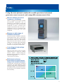
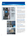
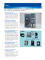
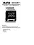
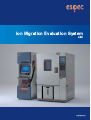
Ion Migration Evaluation System )'3 )*04=>?( Analysis and evaluation of ion migration and evaluation of insulation resistance made more accurate, efficient, and easier Evaluations of ion migration and insulation resistance are assuming a greater degree of importance as electronic devices are miniaturized further and mounted with higher density. The “Ion Migration Evaluation System” allows these evaluations to be performed continuously with a high degree of accuracy and efficiency. Environmental testing has been successfully merged with measurements/evaluations. 1 AMI 2 MEASUREMENT EVALUATION SYSTEM ■ MAIN USE ● 6 1 ● 2 ● ● ● ● ● ■ MAIN FEATURES *- '%"!& #!% %#8$ (0 9! !"#% &'%# & "-&&*0 !''&% $ (0 "& &! '&.% !''0 #$ %# &# ! #$#%$!"&'# ( #!% ' ) ● %!! "&! # +& #* 4! %!! +& #* #$ #!% +& #*5: ;<< =<< #$ ><<) 4=<< #$ ><< #% &'  ● #/ &"- $ " & #""%# 0 $ " ! & *%# & "%& !"&$) ● # #!% ! #($ !* # '%!&# "&' %) # # $ * #$ (%&.!* ! #+##( $%* - #!% ) ● '%&+$ &'%#( 0 #$ !#, 0 #"-+$ (0 - %#" & . - - +%& # ! "-#(%!) ● ● ● ● ● ● ● 12 ● 2 ● ● 2 2 2 ● ● ● ● ● 3 ● ● ● 3 1 2 4 5 Utility Using the international standard traceable precision instrument guarantees most accurate and compatible measurement data. We have always earned our customers’ confidence AMI is equipped with highly reliable measurement equipment and an ammeter for micro-electric current that are designed to meet international standards in order to obtain most reliable measurement data. We offer a calibration service to maintain the equipment’s accuracy (ISO / IEC 17025 compliant). Measures a wide range of insulation resistance The unit measures insulation resistances with high accuracy over a wide range from 2×10³ to 1×10¹³Ω at the tip of the measurement cable (3m). The scanner board for the micro-electric current employs an advanced cable arrangement in order to avoid leakage current influences on the printed circuit boards. AMI Low-voltage to high-voltage tests available AMI can offer three range of apply voltage such as (0 - 100V), (0 - 300V*) and (0 - 500V*). Small voltage for precision devices and large voltage for automotive application. *300V and 500V are optional. Multi-channel continuous measurement accurately detects a change in the insulation resistance Continuously measuring the insulation resistance on multi-channels while applying voltage under a high-temperature and high-humidity environment detects the decrease in the insulation resistance more accurately. Measurement equipment (Keithley Instruments, Inc.) :℃±℃ : : : !"× " Ω ± % ±% !"× "#Ω ± % !"× "%Ω $ "$ ""$ 4 Utility Multifunction rack that pursues ease of use improves the workability. System rack Control on 5ch and 25ch basis Individual test programming on a module basis has been realized. We offer two types of modules, 5-channel and 25-channel. Connection unit Installing the connection unit facilitates the measurement cable connection. The connection unit can be installed in front of the rack or on the left or right side of the rack according to the work environment. High accuracy measurement realized AMI employs a single cable (positive side) and a co-axial cable (negative side) to restrict the influence of micro-noises. The circuitry of AMI keeps the impedance remarkably low in order to realize accurate measurement. Cables are coated with Teflon, which guarantees advantages in resistance to heat, humidity, and voltage. SIR test coupon type IPC-B-24 and test board rack (optional) SIR test coupon type IPC-B-24 and test board rack conforming to IPC-B-24 as stipulated in ISO 9455-17 for efficient SIR testing. The test board rack holds up to five PCBs, and allows measurement of up to 20 channels. Connectors (optional) Connection unit We offer connection jigs tailored to the specimen as an option. Connection jigs facilitate the connection between a specimen and a cable and improves the test efficiency. Global environmental problems Components are mounted by lead-free soldering. In addition, power consumption is reduced by 24% (in comparison with the previous model) in consideration of global environmental problems. *except for purchased items such as PCs and measuring instruments. 5 SIR test coupon type IPC-B-24 and test board rack type A (optional) Utility Tests simplified by interaction of the measurement system with various environmental test chambers. Interaction with the environmental test chambers Interaction with the environmental test chambers enables accurate measurement and makes the best use of the test chambers. AMI can connect up to 3 environmental test chambers for testing. Real-time monitoring of temperature and humidity AMI monitors and records the temp. and humid. inside the environmental test chamber. Data is recorded simultaneously with the measurement by the measurement system. The statistics processing software displays the recorded data in synchronization with the data of the resistance value. Example of AMI with connected the Bench-top type temp. (& humid.) chamber Temp. and humid. delay-control when interacting with the environmental test chambers When interacting with the environmental test chambers, rapidly increasing the humid. at the beginning of the test could generate dew condensation on the surface of the specimen. The temp. and humid. delay-control prevents the effects of the dew condensation on the specimen. Additionally, test scheduling is possible (start, pause, and stop). Network ! " Windows R AMI Safety design guaranteed by abnormality detection When a failure occurs in the environmental test chamber or in AMI during testing, the network system protects the specimen from stress voltage and saves data until the failure is found. # $ Remote processing of the test data (optional) LAN-compatible software enables remote test checking and data processing, such as from a remote office. Additionally, we offer software licenses according to the number of users so that multiple PC monitoring is possible. 6 Evaluation AMI employs a measurement method for insulation resistance that meets various types of test requirements such as ion migration evaluation, insulation deterioration characteristics evaluation, and so on. ● ' & & ( %) %)* Measurement condition , * - .℃, % % - / 0# 1 % - / 0# 1 - + Ω + + ! " # % & $ % + + + Insulation resistance value decline drastically to below 1MΩ + + ' ( 2, 3) & *The data above is the measurement data obtained from the ion migration evaluation system and processed using Excel (spreadsheet software). 7 Ion migration evaluation The insulation resistance on each channel is measured at the preset measurement cycle (6 minutes at minimum) and the results are saved. AMI employs batch charging that enables the measured voltage charging within any time frame. Characteristics evaluation of insulation deterioration The stress voltage and measurement voltage can be set individually. The charging time, which is for measurement when voltage is applied for a given length of time, can also be set. When no stress voltage (0V) is selected in the test condition settings, the insulation resistance of the voltage applied only at measurement can be measured. Evaluation Continuous measurement mode with stress voltage When stress voltage and measurement voltage are same, you can save test time by using this mode. It will use stress voltage as measurement voltage without recharging by measurement voltage. The test time is defined as accumulation of stressed time. The time for measurement (charge and measure) is not count as the test time. ● Measurement voltage Stress voltage 100V Operating condition Stress voltage applying period One shot charge To measure the insulation resistance, the sample(s) must be charged before measurement. AMI will charge by module (either 5 channels or 25 channels) and saving test time rather than charge and measurement one by one. Individual voltage supply per channel One channel with one power supply guarantee no effect of voltage drop by leak on other channels. Each channel has also individual voltage monitor to secure correct voltage applied to each channel. In the measuring mode of continuously applied stress voltage ● 100V 100V A Measuring period Stress voltage applying period 100V Measurement voltage Stress voltage Operating condition 50V A 50V Stress voltage applying period Measuring period Stress voltage applying period Voltage that is actually applied onto the specimen Accumulated stress voltage applying time (test time) No interruption of voltage supply with specially designed scanner ESPEC designed scanner guarantees “no interruption of voltage apply” from stress to measurement. It is possible by the control from its voltage supply. (same on stress and measurement) 8 FAILURE RECOGNITION There are three recognition methods for various stage of failure. Leak-touch behavior continuous evaluation ● In the case where a failure is detected Resistance/Ω Detection point of instantaneous leakage current (detection sensitivity 100µsec/ch) Detection of the leakage current Leak-touch behavior detection record Leak-touch behavior detection mode Time/h ● In End of the measurement the case where the resistance value returns to normal during behavior detection Detection point of instantaneous leakage current (detection sensitivity 100µsec/ch) Resistance/Ω Detection of the leakage current The resistance value returns to normal Measurement resume Leak-touch behavior detection mode Time/h 9 Three recognition methods By set exact value (absolute value), change rate (%) and change amount. You can use these three failure criteria to set the limit (threshold) on your test on each channel. Absolute value: You can set exact resistance value for AMI to recognize the failure. Change rate (%): You can set % change for AMI to recognize the failure. Change amount: You can set the value of change in resistance for AMI to recognize the failure. “Leak Touch” detection and recognition Between the measurement interval, leak detector can detect any small leak on each sample by their stress voltage. You can set any amount of leak current that AMI can recognize the failure. It is completely separate circuitry from measurement. Leak touch observation mode (Optional) Migration often come and goes by burning dendrite after its short and shows resistance recovery. This option enable to observe this “come and goes” or “recovery of resistance”. You can set allowable criteria such as the value to judge recovery, how many times to be allowed and how long it should take to recover. SOFTWARE ● Main window* ・Test monitoring ・Real time display of the resistance value, temperature inside the chamber, channel on which a failure occurs ・Auto link to the data processing software ・Test control (start, stop, pause, and restart) * The picture above shows AMI-075-S-5. ● Test condition registration ● Test setting ● Test details Set the test duration, interval, measurement voltage, applied stress voltage, limit value, etc., and register in a file. You may enter several conditions accordingly. The window above selects the test module, sets the file name of the data to be saved, sets the chamber that it interacts with, whether or not to output the text data, the leak-touch behavior mode, comment entry, and so on. Select test channel and condition. (Select from registered test condition file) ● Graphic ● Data ● Weibull display Current test data and previous data are graphically displayed. Graph can be arranged by selecting the channel, setting display, and cursor display. display Displays current test data and previous data. Analysis (optional) Data-processing software (with a statistical processing function) enables Weibull analysis of test data, as well as the plotting of normal probability and logarithmic-normal probability. 10 SYSTEM BLOCK DIAGRAM ! ) ● 74 8 ) -2-+ 1×-21A 09: ・ # 60 &5 *% # " $ ・ ! " # $ ! ' ● ( # 1, # ");-22 #$ ・ % & % # # ・' (# # ・) (# % "* # +,-. /# 0 0$ ・ ) 1, # % -23Ω to -2-3Ω ・! ! % ・# & # ・ 4 # 11 SPECIFICATIONS # $ " #$ !" 1$ 2+ & 3% ( % × × $ " × × $ " " ' 4 × × + − & 1$ 2+ ± 4% + % + % " ' / 0 & < " # * - # ,-. # * - + / 0 & / 0 & ± 4% @ % 3% ( % × × $ " × × $ " × × $ " × × $ " 4 × × & &6 &6 & &6 &6 + + + + / 3 0 ( / 3 0 ( # 5. * ." * ." ! + ℃ ! + ℃ , 6 7" 6 6 7" 6 . * +6 −6 #( " * 6 89 :" ;< ; 6 89 :" ;< ; 16 × 54 × &=9 16 × 54 × &=9 ( )* +$ " " %< %< %< 9 %< . ?< % ?< % ?< 9 % ?< 9 % %< %< %< 9 %< ?< % ?< % ?< 9 % ?< 9 % ' ! × Ω$ . ! " " $ * ' ! $ A . MODEL ACCESSORIES A M I ― ― S ― ● ● ● ● ● ● ● User’s manual System controller Uninterruptable power supply Micro-current ammeter (equipped with electrometer 6514) Setup CD GPIB board PPI board 12 OPTION Additional channel (25 channel basis) Test board rack type A The channels can be added according to the capacity of the system (150 channels at maximum on 25 channel basis). Test board rack for SIR test coupon type IPC-B-24. Post leak-touch behavior detection mode software Measurement cable for 25 channel (standard type 1.5m) We offer measurement cables for 25 channels including both the positive side and the negative side separately from the standard accessories. We also offer 3m cables as requested. The post leak-touch behavior detection mode software continuously checks and detects the leakage current flowing between the specimens and the behavior unique to the ion migration. LAN-compatible software SIR test coupon type IPC-B-24 LAN-compatible software enables remote test checking and data processing, such as from a remote office. * License for multiple PC monitoring requires an additional cost. Printed circuit boards that comply with IPC-B-24 specified in ISO 9455-17. Extended cable that connects the scanner unit and the connection unit We offer 4m cables (standard type 2.5m). Emergency stop switch Data processing software (with statistical processing software) Stops the system immediately. Weibull analysis is installed in addition to the standard statistical processing software. Communication cable E-BUS Board holder We offer various types of board holders. (Connection terminal: screw-type) 13 5, 10m VARIOUS ENVIRONMENTAL TEST CHAMBERS〈SOLD SEPARATELY〉 Platinous K Series Platinous Series is the series that has been developed out of a desire for new environment test standards for ideal environmental test chambers, and has improved its credibility, performance, operability, and safety. PR PL PSL PH −20 to +100℃ 120, 225, 408, 800 −20 to +150℃ −40 to +100℃ −40 to +150℃ 20 to 98%rh −70 to +100℃ 306, 800 −70 to +150℃ +10 to +100℃ 60 to 98%rh 120, 225, 408, 800 Bench-Top Type Temperature (& Humidity) Chamber The bench-top type temperature & humidity chamber plays a significant role to ensure credibility in the electronics devices’ R&D field. The bench-top type temperature &humidity chamber is the compact bench test equipment that is appropriate for one chamber for each worker. The bench-top type temperature &humidity chamber saves energy and reduces electricity with a unique refrigeration variable control system.. SH-221 SH-241 SH-261 SH-641 SH-661 −20 to +150℃ −40 to +150℃ −60 to +150℃ 22.5 30 to 95% −40 to +150℃ −60 to +150℃ 64 Highly Accelerated Stress Test System (HAST Chamber) The highly accelerated stress test system has functionality that has been developed based on the bias test that applies constant voltage and signals. We offer two types of control that includes two-mode standard type: the unsaturated control and heat exchange, and the M type that is the threemode type with dry & wet-bulb temperature control, unsaturated control and heat exchange. The M type complies with the international standards IEC-60068-2-66. EHS-211 (M) +105 to +142.9℃/ 75 to 100%rh 2 EHS-221 (M) 0.020 to 0.196Mpa (0.2kg to 2.0kg/cm ) +105 to +162.2℃/ 75 to 100%rh EHS-411 (M) 0.020 to 0.392Mpa (0.2kg to 4.0kg/cm2) 18 46 18 14 http://www.espec.co.jp/english Head Office 356, T enj i nbas hi , Ki t ak u, Os ak a5308550 , J apan : T el 81663584741 F ax: 81663585500 ESPEC NORTH AMERICA, INC. : T el 16168966100 F ax: 16168966150 ESPEC EVALUATION & TEST SYSTEMS, INC. : T el 14085924059 F ax: 14087784353 ESPEC EUROPE GmbH : T el 498918939630 F ax: 4989189396379 ESPEC ENVIRONMENTAL EQUIPMENT (SHANGHAI) CO., LTD. Head Office : T el 862151036677 F ax: 862163372237 BEIJING Rep. Office : T el 861064627025 F ax: 861064627036 GUANGZHOU Rep. Office : T el 862083317826 F ax: 862083317825 SHENZHEN Rep. Office : T el 8675583674422 F ax: 8675583674228 SUZHOU Rep. Office : T el 8651268664007 F ax: 8651268601994 WUXI Rep. Office : T el 8651082735036 F ax: 8651082735039 ESPEC TEST TECHNOLOGY (SHANGHAI) CO., LTD. : T el 862168798008 F ax: 862168798088 ESPEC (MALAYSIA) SDN. BHD. : T el 60389451377 F ax: 60389451287 ESPEC GROUP ESPEC CORP. has been assessed by and registered in the Quality Management System based on the International Standard ISO 9001:2000 (JIS Q 9001:2000) through the Japanese Standards Association (JSA). ● ESPEC CORP. ESPEC ENGINEERING CORP. ESPEC KANSAI CORP. ESPEC ENVIRONMENTAL TEST TECHNOLOGY CENTER CORP. ESPEC BUSINESS CREATE CORP. Specifications are subject to change without notice due to design improvements. Windows R is a trademark or registered trademark of Microsoft Corporation in the U.S.A. and other countries. Other corporate names and trade names mentioned in this catalog are trademarks or registered trademarks. ● W11B18C03 (The contents of this catalog is as of November, 2006.) ● Printed on recycled paper.