1
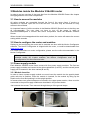
3GHD256256L / SD256256L VikinX Modular 256x256 Router User manual Rev. E Nevion Nordre Kullerød 1 3241 Sandefjord Norway Tel: +47 33 48 99 99 nevion.com 3GHD256256L / SD256256L Rev. E Nevion Support Nevion Europe Nevion USA P.O. Box 1020 3204 Sandefjord, Norway Support phone 1: +47 33 48 99 97 Support phone 2: +47 90 60 99 99 1600 Emerson Avenue Oxnard, CA 93033, USA Toll free North America: (866) 515-0811 Outside North America: +1 (805) 247-8560 E-mail: [email protected] See http://www.nevion.com/support/ for service hours for customer support globally. Revision history Current revision of this document is the uppermost in the table below. Rev. Repl. Date E 4 2015-05-13 4 3 2011-01-26 3 2 2 1 2010-09-27 2010-07-21 1 0 2010-03-02 0 - 2010-01-28 Sign Change description Cover page update; DoC removed; no other changes to content Added information about minimum PSU load in Chapters 2.2 and 3.3.3. Changes in text due to required use of two PSUs in each section as standard solution. NBS Added description of ground strap connection in chapter 3.3.1. Added pictures in Chapters 3.5.1 and 3.5.2. Updated Declaration of Conformity. NBS Corrected Cable EQ specification for 3Gbps. MR/RB Major update. Added some signal specs in Chapter 2 + minor NBS changes. NBS First release of new 3G frame. MB nevion.com | 2 3GHD256256L / SD256256L Rev. E Contents 1 Product overview ................................................................................................................ 4 1.1 Main features................................................................................................................... 4 1.2 Product versions .............................................................................................................. 4 2 Specifications ..................................................................................................................... 5 2.1 Mechanics ....................................................................................................................... 5 2.2 Power supply ................................................................................................................... 5 2.3 Control............................................................................................................................. 5 2.4 Video specifications ......................................................................................................... 6 2.5 Front view ........................................................................................................................ 7 2.6 Rear view ........................................................................................................................ 8 3 Modules inside the Modular 256x256 router ......................................................................10 3.1 How to access the modules ............................................................................................10 3.2 How to configure the router and modules .......................................................................10 3.3 Power supply module .....................................................................................................10 3.4 System Controller – Multicon ..........................................................................................13 3.5 Main X-point modules – XC-M256128-3GHD .................................................................16 3.6 I/O X-point modules – XC-3GHD-M3232 ........................................................................20 3.7 Flashlink section .............................................................................................................22 4 Router communication and control ....................................................................................26 5 Connecting signal cables to the router ...............................................................................27 6 Before calling Nevion Support ...........................................................................................28 7 Serial number overview .....................................................................................................29 General environmental requirements for Nevion equipment .................................................30 Product Warranty .................................................................................................................31 Important notes regarding Software in the VikinX Modular router family range .....................32 Appendix A Materials declaration and recycling information .................................................33 nevion.com | 3 3GHD256256L / SD256256L Rev. E 1 Product overview The Modular SDI Router is part of the VikinX Modular products range, offering up to 256x256 3G-SDI, HD-SDI or SD-SDI X-points. This top of the line router provides a very compact frame, fully hot-swappable architecture, built-in dual redundant power supply and fully redundant controller functions. Starting with the size of 32x32, the router can be expanded under operation with 32x32 increments. Advanced control features like TCP/IP interface and SNMP agent, as well as comprehensive surveillance of the router’s vital parameters are available via the Multicon Monitoring and Control system. The Modular 3G/HD/SD-SDI router provides output reclocking and input (cable) equalization; all of which can be turned on/off on an individual basis. As for our well known VikinX compact router series low power consumption has been important. VikinX Modular provides a fully hot-swappable architecture, meaning that all components are front loaded without any active components on the rear panel. VikinX Modular provides all important 3rd party control interfaces allowing the control of our routers through 3rd party management software. On top of that the THOR management package allows control of the most common 3rd party routers. This enables you to utilize existing routers and management systems from other manufacturers and still draw the advantages of implementing VikinX Modular in your routing application. 1.1 Main features 256x256 3G/HD/SD-SDI router Uses VikinX Modular components I/O boards, PSU and controller Additional 8 Monitor outputs Extended router lines (16x8); makes it possible to add standard Flashlink cards in the router and control them like a regular router input/output Provides all main features known from VikinX Modular HD/SD routers Lowest power consumption available, approx. 560W 3G-SDI, HD-SDI, SD-SDI, DVB-ASI, MADI and AES-3id Audio in one frame All active components hot-swappable and front loaded 1.2 Product versions The following versions of the VikinX Modular 256x256 Router are available: FR-256256-MR-3GHD 3GHD256256L SD256256L 1 256x256 L frame for Multi rate 3G-/HD-/SD-SDI (19.4Mbps, 143Mbps - 2.97Gbps), 21RU. Incl. single Power Supply (2x Power-SM1) and Multicon VX-MOD. Router for 3G-SDI (Multi rate; 143Mbps - 2.97Gbps), 19" 21RU, fully equipped 256x256. Incl. single Power Supply (2x Power-SM1) and Multicon VX-MOD. Router for SD-SDI (19.4Mbps, 143Mbps - 540Mbps), 19" 21RU, fully equipped 256x256. Incl. single Power Supply (2x Power-SM1) and Multicon VX-MOD. Specify AC or DC option upon purchase. nevion.com | 4 3GHD256256L / SD256256L Rev. E 2 Specifications 2.1 Mechanics Dimensions: Frame weights: Router weights: Backplane card: X-point Modules: System Controller: HxWxD = 924x483x340mm, (19”, 21RU). 35.4kg; Weights above include standard equipment according to Price List item specification. 3GHD256256L / SD256256L (21RU): 48.2kg Weight of fully populated router frame. 256x256 (21RU). Main X-point modules: 256x128 I/O X-point modules: 32x32 1 Multicon2 card required, 1 redundant card is optional. 2.1.1 Emission/Immunity and safety standards Emission/Immunity standards: Safety standards: Compliant with CE EN55103-1 and 2, FCC part 15. Compliant with CE EN60950, UL-1950/CSA22.2. 2.2 Power supply Built-in power supply Total power consumption: AC Supply voltage range: Minimum load: AC Mains connector: Optional DC/DC power supply: DC Supply voltage range: DC Mains connector: Alarms: Alarms connector: 4 modules included (2 per section). <600W. 90-130VAC / 180-254VAC, switchable, 50-60Hz, 2x300W. 10% of maximum load. IEC 320, separate input for each PSU module. 36 - 72VDC, 2x300W. Screw terminal, separate input for each PSU module. Power failure alarm on relay contact closure, LED in front, and Open Collector. RJ45. 2.3 Control Standard Features: Serial ports: Connector: Ethernet ports: Connector: EDH & Monitoring: Connector: Monitored parameters: (via Multicon2) Status surveillance: Reclocker option: Input Equalizer option: 2 RS-232/RS-422 for protocol conversion, to VikinX compact control protocol, or to third party protocols. (2x per Multicon2 card). DB9, female. 10/100BaseT Ethernet bus for external router control with new protocol. (1x per Multicon2 card). RJ45. Error Detection and Handling integrated in monitoring outputs. 1 channel available for switch through inputs. BNC. Loss of signal. Lock and clock rate on reclockers. Module temperature. Internal module voltages. On each board with LED, and via system controller. Bypass of reclocking (from system controller). Bypass of input equalization (from system controller). Syscon may be applied instead of Multicon VX-MOD in the router until further notice. nevion.com | 5 3GHD256256L / SD256256L Synchronization handled by Multicon2: Rev. E - Analog Black&Burst, looped. Both PAL and NTSC supported. Tri-Level, Looped. For HD signal formats only. Distribution of synchronization signals between several routers. Connector(s): BNC. Configuration storage: Removable compact flash card. Other Features: Video switching synchronized on selectable field- and line number. Monitoring output on separate channel from each module. 32x1 switch on separate level. (Same as EDH channel). SNMP agent, included with Multicon3. Optional Features: Redundant control: Redundant Matrix Control using 2x Multicon2. 2.4 Video specifications Supported formats: Broadcast: - 19.4Mbps and 143Mbps – 2.97Gbps. DVB-ASI, SMPTE 259M, SMPTE 292M, SMPTE 310M and SMPTE 424M. Electrical signal inputs, SD256256L: Standard: SMPTE 259M. Data rate: 19.4Mbps, 143Mbps – 540Mbps. Connector: 75 ohm BNC female. Impedance: 75 ohm nominal. Return loss: > 15dB (5 – 540MHz). Cable equalization: 0 to 250m, typical Belden 8281. Electrical signal inputs, 3GHD256256L: Standard: SMPTE 259M, SMPTE 292M and SMPTE 424M. Data rate: 19.4Mbps, 143Mbps – 2.97Gbps. Connector: 75 ohm BNC female. Impedance: 75 ohm nominal. Return loss: >15dB (5MHz – 1.5GHz); >10dB (1.5GHz – 3GHz). Cable equalization: 0 to 70m @ 3Gbps, typical Belden 1694A; 0 to 100m @ 1.5Gbps, typical Belden 1694A; 0 to 200m @ 270Mbps, typical Belden 1694A; Electrical signal outputs, SD256256L: Connector: 75 ohm BNC female. Impedance: 75 ohm nominal. Return loss: > 15dB (5 – 540MHz). Signal level: 800mVp-p ±10%. Signal polarity: Non-inverting with respect to inputs. Electrical signal outputs, 3GHD256256L: Connector: 75 ohm BNC female. Impedance: 75 ohm nominal. Return loss: >15dB (5MHz – 1.5GHz); >10dB (1.5GHz – 3GHz). Signal level: 800mVp-p ±10%. Signal polarity: Non-inverting with respect to inputs. Signal transition (both video formats): 3 GYDA-VX must be applied for SNMP agent if Syscon is used; only Multicon includes SNMP agent. nevion.com | 6 3GHD256256L / SD256256L Jitter: Rev. E - Reference inputs: Number of inputs: Connector: Return loss: Signal format: Signal level: Field selectivity: Timing adj. range: < 0.2 UI (HD-SDI and SD-SDI); < 0.3 UI (3G-SDI). 2 standard, both reference signals supplied to both system controllers when used in redundant mode. 75 ohm BNC female, loop-thru. >40dB (100kHz – 5MHz) >35dB (5 – 10MHz). NTSC or PAL Black&Burst or HD Tri-Level according to SMPTE 274M, SMPTE 276M. Nominal 1.0Vp-p. Odd/Even field selectable. 0-20 lines in 1 line steps. Vertical Interval Switching Point: Manual configuration with options fully in accordance with SMPTE RP168. 2.5 Front view Flashlink modules Dual Power supply modules (C+D) I/O X-point modules – XC3GHD-M3232 (#5-8) Main X-point modules – XC-M256128-3GHD I/O X-point modules – XC3GHD-M3232 #1-4) Multicon Gyda* System Controller – Multicon Dual Power supply modules (A+B) Note that XC-3GHD-M3232 in the figure above can also be XC-SD-M3232, for an “SD only” version, or part of the router. nevion.com | 7 3GHD256256L / SD256256L Rev. E *When using a Multicon Gyda board for controlling the Flashlink section, the position closest to the frame wall shall be used. The other position shall never be populated. 2.6 Rear view Service connectors Flashlink section I/O #129 - 256 I/O #1 - 128 Service connectors The following service connectors can be found on the rear of the Modular 256x256 Router: AC Mains A+B: AC Mains C+D: ±48V A+B: ±48V C+D: Serial A1 and A2: Serial B1 and B2: Ethernet A: Ethernet B: Serial GYDA A: Serial GYDA B: Ethernet GYDA A: Ethernet GYDA B: AC mains power supplies for the lower part of the frame. AC mains power supplies for the upper part of the frame. Optional DC battery power supplies for the lower part of the frame. Optional DC battery power supplies for the upper part of the frame. RS-232 or RS-422 for external control protocols. RS-232 or RS-422 for external control protocols (If redundant system controller is installed). 10/100Base-T Ethernet bus for external router control. 10/100Base-T Ethernet bus for external router control (if redundant system controller is installed). RS-232 or RS-422 for external control protocols (if Multicon Gyda for control of the Flashlink section is installed). Not in use 10/100Base-T Ethernet bus for external router control (if Multicon Gyda for control of the Flashlink section is installed). Not in use nevion.com | 8 3GHD256256L / SD256256L Sync 1 and 2: Power Alarm: SW 1: SW 2: Rev. E Synchronization signal 1 and 2 (in/out). Black&Burst/composite/trilevel sync reference input with passive loop-through for vertical interval switching. Vertical Interval Switching Point: Manual configuration with options fully in accordance with SMPTE RP168. Power fail alarm relay contacts. Separate contact pair for each PSU module that is installed. Contact closes on power failure. See Chapter 3.3.4 for further description. Configurations switch 1. For address set of Multicon Gyda controlling the Flashlink section. Switch 1-3 shall be in “on” position (up), the others shall be in “off” position. See also description in Chapter 3.7. Configurations switch 2 (not in use). nevion.com | 9 3GHD256256L / SD256256L Rev. E 3 Modules inside the Modular 256x256 router In order to get an overview of the parts that form the Modular 256x256 Router this chapter will highlight some of the main components. 3.1 How to access the modules All active modules are accessible through the front of the router frame. If service or inspection is required, open the unit from the front. The door may be removed for easy access to the modules. An important feature of all the modules in the Modular 256x256 Router frame is that they are all hot-swappable. The user does not have to turn off the power in order to remove/reinstall/replace a module with active components inside the Modular 256x256 Router. When a board is hot-swapped and the reset button pushed, the router will restore the current setting within seconds. 3.2 How to configure the router and modules Setting up and configuring the router and its modules are done with the Nevion Configurator software. The Nevion Configurator is shipped with the router, or could be downloaded from www.nevion.com. For further instructions on router configuration, please see the online documentation in the Nevion Configurator. When the size of the router is changed by adding or removing of Main X-point modules and/or I/O X-point modules, the Nevion Configurator must be reconfigured to fit to the new router size. 3.3 Power supply module Each Modular 256x256 router frame comes with four power supply modules. The first two power supply modules are inserted in the slots marked with (A and C), and the second power supply pair is inserted in the slots marked (B and D). 3.3.1 Module insertion In order to insert a power supply module one must insert the module via the special plastic guide rails into its position. Once the module is inserted, fix the module by lifting up the handle on the front and pushing it to the upright position. In frames where two ground straps are mounted in the upper power section, these must be connected to the power supply modules as described in the pictures below. Just unscrew the screws. Then remount through the eye of the ground straps. Be aware the horizontal direction. nevion.com | 10 3GHD256256L / SD256256L Rev. E 3.3.2 Module removal In order to remove a power supply module, one must pull down the handle on the front downwards to a horizontal position, and pull the module out with the bar on top of the power module. 3.3.3 How to connect power to the Modular 256x256 Router On the back of the frame, there are eight power connectors. Four of these connectors are for AC mains connections; the other four connectors are for optional DC battery connections. Use an IEC 320 connector to connect AC mains to the Modular 256x256 router frame. There is a switch on the right hand side of the power supply module that selects mains voltage. The mains voltage can be either 110VAC or 230VAC. This switch must be set in the correct position, depending on the mains voltage on the router’s site. Failing to select correct AC mains voltage properly may damage the Power Supply Unit. Since all power supply modules shall be mounted, all 4 AC mains connectors must be used, each pair (A+C and B+D) preferably from two different mains circuits. DC battery power is connected to the frame with screw terminals. If the frame is equipped with two power supply modules, two DC battery connections are used. However, if the frame is equipped with redundant power supply modules, all four DC battery connectors must be used, each pair (A+C and B+D) preferably from two different battery circuits. A combination of redundant power supply, using both AC mains and DC battery, is possible. The frame must then be equipped with two power supply modules of each type, and two AC connectors and two DC connectors must be used. Minimum load specification for VikinX Modular PSU is 10% of maximum load. This means that unused PSU modules should not be connected to AC mains, or DC battery. Unused PSU modules that are connected to AC mains, or DC battery, may show blinking alarm LEDs and produce clicking sounds. This is not dangerous, but we recommend that the user disconnects unused PSU modules from their respective sources. 3.3.4 Status LEDs and relay contacts The Status LED indications on AC PSU modules are slightly different from those of DC PSU modules. There are 2 LEDs on the front of each power supply module, and they indicate the following: AC PSU modules: Upper, RED LED: Lower, GREEN LED: DC PSU modules: Upper, RED LED: Lower, GREEN LED: Normally OFF. If it is ON, there is a power supply failure, indicating that the power supply module must be replaced. Normally ON. If it is OFF, there is no mains power supplying the frame. Normally OFF. If it is ON, there is a faulty output voltage, indicating that the power supply module must be replaced. Normally ON. If it is OFF, there is no input power supplying the frame. nevion.com | 11 3GHD256256L / SD256256L Rev. E There are also two Power fail alarm relay contacts on the rear side of the frame; see Chapters 2.2 and 2.5 for details. Each installed PSU module has a separate pair of contacts. The relay contact is normally open, and the contact closes on power failure. The PSU module A alarm is formed by contact between Pin 3 and Pin 6 (Green pair) The PSU module B alarm is formed by contact between Pin 1 and Pin 2 (Orange pair) nevion.com | 12 3GHD256256L / SD256256L Rev. E 3.4 System Controller – Multicon Each VikinX Modular frame comes with either one or two system controller cards, Multicon VX-MOD. One Multicon VX-MOD is necessary to control the router; dual redundant Multicon VX-MOD is an option. Please see separate Multicon VX-MOD manual for details about configuration and control. Multicon VX-MOD can be enabled for 3rd party control interfaces as an option. Please contact your Nevion representative for details. Further, Multicon provides the user with an SNMP agent. Your Multicon VX-MOD card(s) may be inserted in any of the two slots (A) and (B). All the configuration parameters, control parameters, etc. are stored in the Compact Flash (CF) memory of the Multicon card. This provides a high grade of security for the user, as he just needs to remove the CF card if the Multicon card fails, and install this CF card on a new Multicon card. The router will not notice the difference. 3.4.1 Card insertion The frame is equipped with plastic guide rails to align the Multicon cards into their respective positions. Slide the card into the plastic guide rails inside the frame until the red handle is close to the frame front. A detailed description of the last part of the insertion process is shown in the figure below. On the top of the card tray, there is a hole above each module slot. When the tip of the handle is just below this hole, start to push the handle downwards as in the figure. The tip of the handle enters the hole and the card is locked and proper contact ensured when the handle is in downright position. Do not use excessive force; the card should enter easily – proper insertion is almost effortless. 3.4.2 Card removal To remove a module card from the sub-rack frame, release the card by moving the red handle until it is in horizontal position, as shown in the figure below. Then pull the card out of the sub-rack with the red handle. nevion.com | 13 3GHD256256L / SD256256L Rev. E 3.4.3 Status LEDs and reset button There are 4 LEDs on the front side of the Multicon VX-MOD card, and a reset button on the rear side. Status LEDs The LEDs indicate the following: Diode Red LED Status Card error. Eth Warn Load Yellow LED Not applicable. Green LED Overall status of the card is OK Not applicable. Full duplex connection. Half duplex connection. Abnormal situation: no functional error, but a situation that requires attention. High load4 on the μController. May occur during system start up and software reconfigurations / upgrades. Not applicable. Normal situation. Medium load on the μController. Low or normal load on the μController. No light Card has no power, or is not inserted correctly. No Ethernet link established; check cable. Not applicable. Not applicable. 4 Red LED means 100% load on the Multicon. This may occur for intervals up to approximately 20 seconds. Longer periods may indicate that there is something wrong with the Multicon. nevion.com | 14 3GHD256256L / SD256256L Rev. E Reset button The reset button on the rear side is used to perform a hard reset of the card. Do not perform a hard reset, unless the situation demands this. By performing a hard reset, the user looses control of the router, and will not get control of the router until approximately 20 seconds after releasing the reset button. 3.4.4 CF-card and battery All the information regarding the router configuration, as well as information regarding control panels that are connected to the router, is stored in the Compact Flash card on the Multicon card. If it is necessary to remove and/or insert a CF card, the following must be done: 1. Remove the Multicon card from its slot, according to the description earlier in this manual. 2. Slide the CF card out of its socket, and insert the new CF card into the socket. 3. Insert the Multicon card into its slot, according to the description earlier in this manual. The battery is to ensure proper working of the on-board real time clock used by Multicon, even when the router is powered down. If it is necessary to remove and/or insert a battery, the following must be done: 1. Remove the Multicon card from its slot, according to the description earlier in this manual. 2. Slide the battery out of its socket, and insert the new battery into the socket. 3. Insert the Multicon card into its slot, according to the description earlier in this manual. nevion.com | 15 3GHD256256L / SD256256L Rev. E 3.5 Main X-point modules – XC-M256128-3GHD The XC-M256128-3GHD is the main X-point card in the VikinX Modular 256x256 router frame. A maximum of two XC-M256128-3GHD cards can be inserted into the 21RU frame, providing control of signals between each 32x32 X-point module. An FR-256256-MR-3GHD equipped with 8x 32x32 X-point modules and 2x XC-M256128-3GHD modules builds a 256x256 router; with only 1x XC-M256128-3GHD module inside, the router size becomes 256x128. Note that it is not possible to build a 128x256 router; only 256x128 or 256x256. If there are no XC-M256128-3GHD cards in the frame, or the present XC-M256128-3GHD cards are not working, the user has still the ability to control each of the XC-3GHD-M32325 cards in the frame as independent 32x32 routers. This feature is useful when configuring the router, considering protection of important I/O combinations by configuring them to the same 32x32 I/O part of the VikinX Modular 256x256 router frame. XC-3GHD-M3232 Input 1-32 Input 33-64 XC-M256128-3GHD Input 65-96 Input 97-128 Input 129-160 Input 161-192 Input 193-224 Input 225-256 Output 1-32 Output 65-96 Output 129-160 Output 193-224 Output 33-64 Output 97-128 Output 161-192 Output 225-256 3.5.1 Card insertion To insert an XC-M256128-3GHD card, slide the module along the plastic guide rails into its position. On both sides of the card tray there is a hole next to each module slot. Use the two handles, which are located on the front of the module to seat the module. 5 Note that XC-3GHD-M3232(-B) in this chapter also applies to XC-SD-M3232. nevion.com | 16 3GHD256256L / SD256256L Rev. E When the tip of both handles is just next to these holes, start to push the handles simultaneously inwards the card. The tip of the handles enters the hole and the card is locked and proper contact ensured when you hear a click from both handles. Note that it may be necessary to press hard when inserting the X-point card(s). Be sure to press the card(s) firmly into the frame, before locking the handles. nevion.com | 17 3GHD256256L / SD256256L Rev. E Note that the reset button shall always be pushed immediately after card insertion to ensure a shortest possible start-up time. 3.5.2 Card removal To remove an XC-M256128-3GHD card from the frame, release the card by pushing the red knobs on each handle until each handle releases from its locked position. Then pull both handles simultaneously, and pull the card out of the frame. nevion.com | 18 3GHD256256L / SD256256L Rev. E 3.5.3 Status LEDs The front view of an XC-M256128-3GHD card is as follows: A detailed look at the LEDs is shown below: The 10 LEDs on the front of each XC-M256128-3GHD card indicate the following: Diode BEAT SYST.ERR SER.CH2 SER.CH1 TEST 1 FAN 2 PWR* TEMP FAN1 TEST 2 Red LED Green LED Blinks when the μController is running (heartbeat). A fault is detected on the card. The system controller lights, or turns off this LED. This is used for simplifying the identification of a module. Blinks each time the μController of the X-point card answers a message from the system controller on communication channel 2. Blinks each time the μController of the X-point card answers a message from the system controller on communication channel 1. No special function; for internal testing purpose only. Fan error, when the fan speed is The fan speed of FAN2 is in its normal outside its normal range. FAN2 is the range. FAN2 is the innermost fan on innermost fan on the X-point card. the X-point card. Any of the voltages on the card is All internal voltages are OK. outside their legal range. The temperature of the card is outside The temperature of the card is OK. its legal range. Fan error, when the fan speed is The fan speed of the first fan is in its outside its normal range. FAN1 is the normal range. FAN1 is the outermost outermost fan on the X-point card. fan on the X-point card. No special function; for internal testing purpose only. Note that all alarm ranges are configurable from the system controller. *When only a Main X-point module and no I/O X-point module is mounted in a section, the “PWR” LED of the Main X-point module may indicate an alarm (red) though everything is all right. The LED will turn green immediately when one I/O X-point module is mounted in the connected section. This problem has been resolved for new boards and is valid only with the first release of boards. 3.5.4 Service switch and reset button There is one slide-switch and one push-button switch on the board, as shown in the figure below. nevion.com | 19 3GHD256256L / SD256256L Rev. E When the RESET button is pushed and released, the μController of the X-point card resets and restarts its operation with its default settings, or the settings stored in EEPROM. The slide switch next to the RESET button is a service switch: The knob must always stay in the position indicated with “NORMAL”. The slide switch is for factory use only. 3.6 I/O X-point modules – XC-3GHD-M3232 Note that XC-3GHD-M3232 in this chapter also applies to XC-SD-M3232. Each VikinX Modular 256x256 router frame must be equipped with at least one 32x32 X-point card, XC-3GHD-M3232. A maximum of eight XC-3GHD-M3232 cards can be inserted into the 21RU frame, providing router sizes from 32x32, via 64x64, 96x96, up to 256x256. It is also possible to combine 3GHD and SD routers in the same frame. You may add SD X-point cards into a 3GHD-SDI frame, and vice versa. 3.6.1 Card insertion The XC-3GHD-M3232 cards are inserted in the exact same way as the XC-M256128-3GHD cards. See Chapter 3.5.1 Note that the reset button shall always be pushed immediately after card insertion to ensure a shortest possible start-up time. 3.6.2 Card removal The XC-D-M3232 cards are removed in the exact same way as the XC-256128 cards. See Chapter 3.5.2 3.6.3 Status LEDs The front view of an XC-D-M3232 card is as follows: A detailed look at the LEDs is shown below: nevion.com | 20 3GHD256256L / SD256256L Rev. E The 10 LEDs on the front of each X-point card indicate the following: Diode Red LED Green LED BEAT Blinks when the μController is running (heartbeat). SYST.ERR A fault is detected on the card. The system controller lights, or turns off this LED. This is used for simplifying the identification of a module. SER.CH2 Blinks each time the μController of the X-point card answers a message from the system controller on communication channel 2. SER.CH1 Blinks each time the μController of the X-point card answers a message from the system controller on communication channel 1. TEST 1 No special function; for internal testing purpose only. FAN 2 Fan error, when the fan speed is The fan speed of FAN2 is in its normal outside its normal range. FAN2 is the range. FAN2 is the innermost fan on innermost fan on the X-point card. the X-point card. PWR Any of the voltages on the card is All internal voltages are OK. outside their legal range. TEMP The temperature of the card is outside The temperature of the card is OK. its legal range. FAN1 Fan error, when the fan speed is The fan speed of the first fan is in its outside its normal range. FAN1 is the normal range. FAN1 is the outermost outermost fan on the X-point card. fan on the X-point card. EDH.ERR Indicates EDH status for the selected monitor output. The monitoring output monitors the selected input, but the EDH counter is on the output. Note that all alarm ranges are configurable from the system controller. 3.6.4 Service switch and reset button There are one slide-switch and one push-button switch on the board, as shown in the figures below. The push-button switch (SW2001) is the RESET switch. When this button is pushed and released, the μController of the X-point card resets and restarts its operation with its default settings, or the settings stored in EEPROM. nevion.com | 21 3GHD256256L / SD256256L Rev. E The slide switch: The knob must always stay in the position away from the card front. The slide switch is for factory use only. 3.7 Flashlink section The Flashlink section in the upper, left part of the router makes it possible to switch signals via Flashlink modules and even from one module to another. In this way several Flashlink functions can be introduced in the signal path. Please contact Nevion Sales Dept., or your local Nevion representative for a complete survey of Flashlink modules that are available for this purpose. There are four slots for Flashlink modules and one for the 15V PSU module available in the VikinX Modular 256x256 frame. For connection to/from the router there are a total of 32pcs. SMA connectors; 2x8 inputs (two and two in parallel) and 16 separate outputs. The layout (seen from the front of the router) is as follows: nevion.com | 22 3GHD256256L / SD256256L Rev. E 1 1 16 outputs to Flashlink modules 1 2 1 0 2 3 1 1 4 1 2 5 1 3 5 6 1 4 6 7 1 5 7 8 1 6 8 2 3 3 4 4 5 6 7 8 The layout of the 32 pcs. SMA connectors as seen from the front of the router. 33 8 8 (265-272) (257-264) 32 Mon.6 (278) Input 161-192 Output 161-192 Mon.5 (277) Input 129-160 Output 129-160 8 8 Mon.8 (280) Input 225-256 Output 225-256 Mon.7 (279) Input 193-224 Output 193-224 (257264) 9 8x2 (mirrored) inputs from Flashlink modules Block schematic 256256: Input 1-256 and 257-264 (main 256x128) Output 129-256 and 265-272 and 277-280 Input 1-256 and 257-264 (main 256x128) Output 1-128 and 257-264 and 273-276 Mon.4 (276) Input 97-128 Output 97-128 Control of the Flashlink cards Mon.3 (275) Input 65-96 Output 65-96 Multicon GYDA Multicon VX-MOD Mon.2 (274) Input 33-64 Output 33-64 Flashlink control Router control (opt. redundant) 33 Mon.1 (273) Input 1-32 Output 1-32 32 The picture is illustrating the matrix cards in the frame and the interconnection between them and the SMA connectors for the Flashlink section. There are 2 main X-point cards in the middle, each sending 32+1 signals to 4 IO-cards. Each of the 8 IO-cards are receiving 32 nevion.com | 23 3GHD256256L / SD256256L Rev. E main plus 1 monitor line from its related X-point card and sending 32 signals to both X-point cards. The 32 SMA connectors are located at the upper, left end of the main backplane. Please observe that the Flashlink modules must have dual outputs in order to provide two identical signals to the main X-point cards. The lower X-point card is sending signals to Flashlink output 1-8 (main matrix output 257-264) and the upper one is sending signals to Flashlink output 9-16 (265-272). The Multicon GYDA has to be configured to an address that is not in conflict with the Flashlink cards in the upper section of the router. This is done with the dip switches at the lower backplane, located at the right side on the rear of the router. Configure it to card number 5 by setting SW13 up and the rest down (ref. drawing). SW 14 13 12 11 SW 24 23 22 21 Please observe the following notes when applying Flashlink modules in the VikinX Modular 256x256 frame: The function of the Flashlink section must be decided prior to ordering. This is because the solution will be mounted and fully tested at Nevion before shipping. The solution is not at all suitable for retrofitting and will therefore not be offered as a solution for already delivered routers. nevion.com | 24 3GHD256256L / SD256256L Rev. E Only Nevion provided cable solutions shall be used for connection between Flashlink modules and the router. The 2x8 inputs and 16 outputs are found in the router control system (Multicon) as inputs 257 to 264 and outputs 257 to 272. For control and monitoring of Flashlink modules, one or two (redundant) Multicon Gyda board (s) must be mounted in dedicated slot (s) at the bottom section of the router. Input EQs and Output Reclockers must always be activated in Flashlink modules that are used in the router frame. Input EQs and Output Reclockers in the router’s signal paths connecting to/from the Flashlink section must be activated. When connecting two Flashlink modules via the router, the signal must be looped externally, via the router’s backplane. And Input EQ and Output Reclocker must be activated for the employed backplane ports. nevion.com | 25 3GHD256256L / SD256256L Rev. E 4 Router communication and control You gain access to router for communication and control purposes by connecting either the router’s serial port to your computer and/or by using an Ethernet connection. Please refer to the manual for Multicon VX-MOD for a detailed description of the applicable communication interfaces for your modular router. nevion.com | 26 3GHD256256L / SD256256L Rev. E 5 Connecting signal cables to the router The Modular 256x256 router offers standard 75Ohms BNC connectors for all in- and outputs. See also Chapter 2.6 for rear layout. nevion.com | 27 3GHD256256L / SD256256L Rev. E 6 Before calling Nevion Support The following table shows possible symptoms, and what to do in order to correct possible error sources. Every user should read this before calling Nevion Technical Support. What to do… Depends on AC or DC PSU option. See Chapter 3.3.4. Depends on AC or DC PSU option. See Chapter 3.3.4. There is a card error, indicating that the Multicon card must be replaced. The Warn LED on the Multicon card is RED An abnormal situation has occurred. See Chapter 3.4.3. If the router has redundant PSU modules, check that both modules are properly installed, and are working. If the router has redundant Multicon cards, check that both cards are properly inserted, and are working. The SYST.ERR. LED on one of the X-point A fault is detected on the X-point card. Check cards is RED that it is properly connected. If it is properly connected, the X-point card needs replacement. A FAN LED on one of the X-point cards is The fan speed is outside its legal range, RED indicating that service is necessary. The PWR. LED on one of the X-point cards is Any of the voltages on the card is outside its RED legal range, indicating that service in necessary. The TEMP. LED on one of the X-point cards Any of the temperatures on the card is is RED outside its legal range, indicating that service is necessary. Symptom The lower, GREEN LED on the Power Supply is OFF The upper, RED LED on the Power Supply is ON The Status LED on the Multicon card is RED nevion.com | 28 3GHD256256L / SD256256L Rev. E 7 Serial number overview The following table shows the serial numbers of all parts of your Modular 256x256 Router. Please refer to these numbers when contacting Nevion Europe for product support. Device / Part Frame, including all static cards Power Supply Module #1 Power Supply Module #2 Power Supply Module #3, if included Power Supply Module #4, if included Multicon Card #1 Multicon Card #2, if included Syscon Card #16 Syscon Card #26, if included XC-M256128-3GHD Card #1 XC-M256128-3GHD Card #2, if included XC-3GHD-M3232 Card #1, if included XC-3GHD-M3232 Card #2, if included XC-3GHD-M3232 Card #3, if included XC-3GHD-M3232 Card #4, if included XC-3GHD-M3232 Card #5, if included XC-3GHD-M3232 Card #6, if included XC-3GHD-M3232 Card #7, if included XC-3GHD-M3232 Card #8, if included And/Or… XC-SD-M3232 Card #1, if included XC-SD-M3232 Card #2, if included XC-SD-M3232 Card #3, if included XC-SD-M3232 Card #4, if included XC-SD-M3232 Card #5, if included XC-SD-M3232 Card #6, if included XC-SD-M3232 Card #7, if included XC-SD-M3232 Card #8, if included Additional cards, if applicable… 6 Part / Serial number Only if Multicon is not applied. nevion.com | 29 3GHD256256L / SD256256L Rev. E General environmental requirements for Nevion equipment 1. 2. - The equipment will meet the guaranteed performance specification under the following environmental conditions: Operating room temperature range: 0°C to 45°C Operating relative humidity range: <95% (non-condensing) The equipment will operate without damage under the following environmental conditions: Temperature range: -10°C to 55°C Relative humidity range: <95% (non-condensing) nevion.com | 30 3GHD256256L / SD256256L Rev. E Product Warranty The warranty terms and conditions for the product(s) covered by this manual follow the General Sales Conditions by Nevion, which are available on the company web site: www.nevion.com nevion.com | 31 3GHD256256L / SD256256L Rev. E Important notes regarding Software in the VikinX Modular router family range This product utilizes software components that are licensed with open source licenses. The source code for these components and our modifications are available from: http://labs.nevion.com/open-source/ You may also send Nevion Europe a recordable CD and a self-addressed envelope, and we will burn the contents of http://labs.nevion.com/open-source/ to your CD and send it back to you. This offer is valid for 3 years after purchase of this product. nevion.com | 32 3GHD256256L / SD256256L Rev. E Appendix A Materials declaration and recycling information A.1 Materials declaration For product sold into China after 1st March 2007, we comply with the “Administrative Measure on the Control of Pollution by Electronic Information Products”. In the first stage of this legislation, content of six hazardous materials has to be declared. The table below shows the required information. Toxic or hazardous substances and elements Part Name Lead Mercury Cadmium Hexavalent Polybrominated Polybrominated (Pb) (Hg) (Cd) Chromium biphenyls diphenyl ethers (Cr(VI)) (PBB) (PBDE) FR-256256-MR3GHD O O O O O O XC-M2561283GHD O O O O O O XC-3GHD-M3232 / XC-SD-M3232 O O O O O O Multicon VX-MOD O O O O O O POWER-SM AC / POWER-SM-DC O O O O O O O: Indicates that this toxic or hazardous substance contained in all of the homogeneous materials for this part is below the limit requirement in SJ/T11363-2006. X: Indicates that this toxic or hazardous substance contained in at least one of the homogeneous materials used for this part is above the limit requirement in SJ/T11363-2006. Parts without any of the above mentioned hazardous substances are indicated by the product marking: A.2 Recycling information Nevion provides assistance to customers and recyclers through our web site http://www.nevion.com/. Please contact Nevion’s Customer Support for assistance with recycling if this site does not show the information you require. Where it is not possible to return the product to Nevion or its agents for recycling, the following general information may be of assistance: Before attempting disassembly, ensure the product is completely disconnected from power and signal connections. All major parts are marked or labeled to show their material content. Some circuit boards may contain battery-backed memory devices. nevion.com | 33