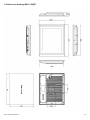
1
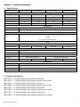
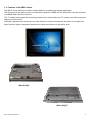
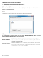
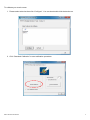
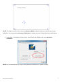
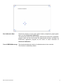
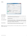
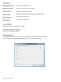
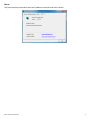
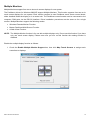
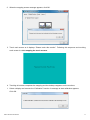
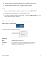
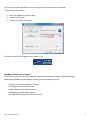
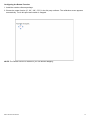
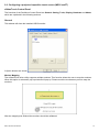
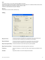
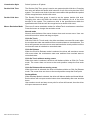
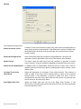
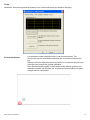
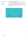
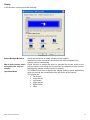
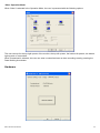
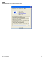
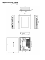
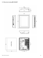
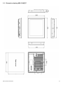
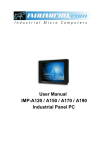
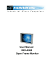
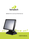
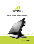
Greenline Industrial Monitors IMD-C Series User Manual ___________________________________ Warning! ___________________________________ This equipment generates, uses and can radiate radio frequency energy and if not installed and used in accordance with the instructions manual may cause interference to radio communications. It has been tested and found to comply with the limits for a Class A computing device pursuant to FCC Rules, which are designed to provide reasonable protection against such interference when operated in a commercial environment. Operation of this equipment in a residential area is likely to cause interference in which case the user at his own expense will be required to take whatever measures may be required to correct the interference. Electric Shock Hazard – Do not operate the machine with its back cover removed. There are dangerous high voltages inside. Disclaimer This information in this document is subject to change without notice. In no event shall Indumicro.com be liable for damages of any kind, whether incidental or consequential, arising from either the use or misuse of information in this document or in any related materials. Table of contents Chapter 1: System description 1.1 Specifications .............................................................................................................................. 1 1.2 Ordering information ................................................................................................................... 1 1.3 Features of the IMD-C series ...................................................................................................... 2 Chapter 2: Touch screen configuration 2.1 Configuring a resistive touch screen (IMD-CxxxT) ...................................................................... 3 2.2 Configuring a projected capacitive touch screen (IMD-CxxxPT) ............................................... 15 Chapter 3: Dimension drawings 3.1 Dimension drawing IMD-C070[P]T ............................................................................................ 25 3.2 Dimension drawing IMD-C080[P]T ............................................................................................ 26 3.3 Dimension drawing IMD-C120[P]T ............................................................................................ 27 3.4 Dimension drawing IMD-C150[P]T ............................................................................................ 28 Chapter 1: System description 1.1 Specifications Model IMD-C070[P]T IMD-C080[P]T IMD-C120[P]T IMD-C150[P]T Display Display type Max. resolution 7” TFT-LCD 8” TFT-LCD 12.1” TFT-LCD 15” TFT-LCD 800x480 800x600 800x600 1024x768 262K 16.2M 16.2M 16.2M 350 350 330 330 140° / 110° 140° / 125° 160° / 140° 160° / 145° Max. color Luminance (cd/m²) View angle (H/V) Touch Screen Type Resistive touch (IMD-CxxxT) / ‘Anti-scratch’ projected capacitive touch (IMD-CxxxPT) Light transmission 80% (IMD-CxxxT) / 90% (IMD-CxxxPT) Connectivity 1 x USB for touch Connectors 1 x VGA 1 x DVI 1 x 3-pin terminal block for power Power Input voltage 9~36V DC Power consumption Max. 2.4W Max. 4.6W Max. 7W Max. 11W Mechanical OSD keypad 5-key keypad located on the backside Construction Aluminum front and chassis IP Rating IP65 front panel Mounting Panel mount / VESA 75 Dimensions (mm) 202 x 149 x 39 Panel mount / VESA 100 231 x 176 x 51 319 x 245 x 52 410 x 310 x 55 Environmental Operating temperature 0~50°C Storage temperature Storage humidity Certification -20~60°C 10 to 90% @ 40°C, non- condensing CE / FCC Class A 1.2 Ordering information IMD-C070T 7” Industrial display with resistive touch screen IMD-C070PT 7” Industrial display with projected capacitive touch screen IMD-C080T 8” Industrial display with resistive touch screen IMD-C080PT 8” Industrial display with projected capacitive touch screen IMD-C120T 12” Industrial display with resistive touch screen IMD-C120PT 12” Industrial display with projected capacitive touch screen IMD-C150T 15” Industrial display with resistive touch screen IMD-C150PT 15” Industrial display with projected capacitive touch screen IMD-C Series User Manual 1 1.3 Features of the IMD-C series The IMD-C series feature an excellent viewing ability for monitoring and control applications. The front panel of the display monitor is sealed with a gasket for NEMA 4/IP 65 rating when it is panel mounted in a NEMA rated cabinet or enclosure. The ‘T’ models are equipped with an analog resistive touch screen while the ‘PT’ models come with a projected capacitive touch screen. Projected capacitive touch screens are not only resistant to scratch and abrasion but also to most chemicals. Apart from that, glass is transparent and does not impair the brilliance of the picture at all. IMD-C070[P]T IMD-C150[P]T IMD-C-Series User Manual 2 Chapter 2: Touch screen configuration 2.1 Configuring a resistive touch screen (IMD-CxxxT) PenMount Control Panel The functions of the PenMount Control Panel are Device, Multiple Monitors ,Tools and About, which are explained in the following sections. Device In this window, you can find out that how many devices are detected on your system. Calibrate This function offers two ways to calibrate your touch screen. ‘Standard Calibration’ adjusts most touch screens. ‘Advanced Calibration’ adjusts aging touch screens. Standard Calibration Click this button and arrows appear pointing to red squares. Use your finger or stylus to touch the red squares in sequence. After the fifth red point calibration is complete. To skip, press ‘ESC’. Advanced Calibration Advanced Calibration uses 4, 9, 16 or 25 points to effectively calibrate touch panel linearity of aged touch screens. Click this button and touch the red squares in sequence with a stylus. To skip, press ‘ESC’. IMD-C-Series User Manual 3 To calibrate your touch screen: 1. Please select a device then click “Configure”. You can also double click the device too. 2. Click “Standard Calibration” to start calibration procedure. IMD-C-Series User Manual 4 NOTE: The older the touch screen, the more Advanced Mode calibration points you need for an accurate calibration. Use a stylus during Advanced Calibration for greater accuracy. Please follow the step as below: 3. Come back to “PenMount Control Panel”, select Device to calibrate, then click Advanced Calibration. NOTE: It is recommended to use a stylus during Advanced Calibration for greater accuracy. IMD-C-Series User Manual 5 Plot Calibration Data Check this function to have touch panel linearity comparison graph appear when you finish Advanced Calibration. The black lines reflect the ideal linearity assumed by Penmount’s application program while the blue lines show the approximate linearity calculated by Penmount’s application program as the result of user’s execution of Advanced Calibration. Turn off EEPROM storage This function disables the write-in of calibration data in the controller. This function is enabled by default. IMD-C-Series User Manual 6 Setting Operation Mode Mouse Emulation This operating mode will send left button down function when user presses, and left button up function when user release its touch. Click On Touch This operating mode will send a mouse click only on user’s touch. Dragging is disabled in this mode. Pen Input Emulation When using “Pen Input Emulation”, the PenMount device driver will not send left mouse button right away, therefore, it is recommended to use this mode with the “press and hold” right mouse button emulation, it will be able to activate right mouse function on “Start Menu” and other utility. Click On Release This operation mode will send a mouse click when user release its touch operation. This feature works well when browsing certain web pages. NOTE: The actual mouse functions generated by the above operating modes can be viewed from the PenMount “DRAW” utility. IMD-C-Series User Manual 7 Beep Sound Enable Beep Sound Turns beep function on or off. Beep on pen down Beep occurs when pen comes down. Beep on pen up Beep occurs when pen is lifted. Beep on both Beep occurs when pen comes down and when it’s lifted. Beep Frequency Modifies sound frequency. Beep Duration Modifies sound duration. Cursor Stabilizer Enable this function to prevent cursor shake. Use press and hold as right click Set the time and area as needed. Edge Compensation The "Edge Compensation" function is used to optimize the cursor accuracy on the edges. It is only supported by "Advanced Calibration", not for "Standard Calibration". IMD-C-Series User Manual 8 About This panel displays information about the PenMount controller and driver version. IMD-C-Series User Manual 9 Multiple Monitors Multiple Monitors support from two to six touch screen displays for one system. The PenMount drivers for Windows 2000/XP support Multiple Monitors. This function supports from two to six touch screen displays for one system. Each monitor requires its own PenMount touch screen control board, either installed inside the display or in a central unit. The PenMount control boards must be connected to the computer COM ports via the RS-232 interface. Driver installation procedures are the same as for a single monitor. Multiple Monitors support the following modes: Windows Extends Monitor Function Matrox DualHead Multi-Screen Function nVidia nView Function NOTE: The Multiple Monitor function is for use with multiple displays only. Do not use this function if you have only one touch screen display. Please note once you turn on this function the rotating function is disabled. Enable the multiple display function as follows: 1. Check the Enable Multiple Monitor Support box; then click Map Touch Screens to assign touch controllers to displays. IMD-C-Series User Manual 10 2. When the mapping screen message appears, click OK. 3. Touch each screen as it displays “Please touch this monitor”. Following this sequence and touching each screen is called mapping the touch screens. 4. Touching all screens completes the mapping and the desktop reappears on the monitors. 5. Select a display and execute the “Calibration” function. A message to start calibration appears. Click OK. IMD-C-Series User Manual 11 6. “Touch this screen to start its calibration” appears on one of the screens. Touch the screen. 7. “Touch the red square” messages appear. Touch the red squares in sequence. 8. Continue calibration for each monitor by clicking Standard Calibration and touching the red squares. NOTES: 1. If you use a single VGA output for multiple monitors, please do not use the Multiple Monitor function.Just follow the regular procedure for calibration on each of your desktop monitors. 2. The Rotating function is disabled if you use the Multiple Monitor function. 3. If you change the resolution of display or screen address, you have to redo Map Touch Screens, so the system understands where the displays are. PenMount Monitor Menu Icon The PenMount monitor icon (PM) appears in the menu bar of Windows 2000/XP/7 system when you turn on PenMount Monitor in PenMount Utilities. The PenMount Monitor has the following functions: Control Panel Opens the Control Panel window. Beep Set Beep function for each device. Right Button When you select this function a mouse icon appears on the desktop. Click this icon to switch between right and left button functions. Exits the PenMount Monitor function. Exit IMD-C-Series User Manual 12 You can opt to display the Mouse Icon in the System Tray instead of on the desktop. To do so follow these steps: 1. Open the PenMount Control Panel. 2. Select the Tools tab. 3. Select the System Tray option. The Mouse Icon will then appear in the System Tray. PenMount Rotating Functions The PenMount driver for Windows 2000/XP supports several display rotating software packages. Windows Me/2000/XP support display rotating software packages such as: • Portrait’s Pivot Screen Rotation Software • ATI Display Driver Rotate Function • nVidia Display Driver Rotate Function • SMI Display Driver Rotate Function • Intel 845G/GE Display Driver Rotate Function IMD-C-Series User Manual 13 Configuring the Rotate Function 1. Install the rotation software package. 2. Choose the rotate function (0°, 90°, 180°, 270°) in the 3rd party software. The calibration screen appears automatically. Touch this point and rotation is mapped. NOTE: The Rotate function is disabled if you use Monitor Mapping IMD-C-Series User Manual 14 2.2 Configuring a projected capacitive touch screen (IMD-CxxxPT) eGalaxTouch Control Panel The functions of the PenMount Control Panel are General. Setting, Tools, Display, Hardware and About, which are explained in the following sections. General This window will show the installed USB Controller. 3 Option buttons are shown: Monitor Mapping The eGalaxTouch driver utility supports multiple monitors. This function allows the user to map the monitors. When this option is selected a pop-up window will pop-up. Please touch the touchscreen panel to map the monitors. After the mapping has finished the monitors should be calibrated. IMD-C-Series User Manual 15 Add This function button is only used to add serial RS232 controllers. eGalaxTouch supports plug and play for USB devices. The icon object for an additional USB controller will be shown automatically in the controller list window when the USB controller is connected with the system USB port. Remove This function is used for serial controllers only. Setting Beep On Touch Check this check box to enable driver to generate a beep sound when touch touchscreen state is switched from untouched to touched state. Beep On Release Check this check box to enable driver to generate a beep sound when touchscreen state is switched from touched state to untouched state. Beep From System Beep Check this check box to make the beep from system speaker. Beep From Sound Card Check this check box to make the beep from sound card. Frequency Adjust this frequency to control the beep sound frequency generated by the driver. Duration Adjust this duration to control the beep sound duration. IMD-C-Series User Manual 16 Linearization Style Select 9 points or 25 points. Double Click Time The Double Click Time group is used to set system double click time. Changing this value will affect the double click behavior for all of the mice devices in the system. Two continuous clicks in the same area within this specified time period will be recognized as a double click event. Double Click Area The Double Click Area group is used to set the system double click area. Changing this value will affect the double click behavior for all of the mice devices in the system. Two continuous click in the specified area within the specified double click time will be recognized as a double click event. Mouse Emulation Mode There are 5 mouse emulation modes for eGalaxTouch touchscreen controllers. Press the button to change the emulation mode. Normal mode Normal mode behaves like mouse button down and mouse move. User can select this mode to select and drag an object. Click On Touch With this Click On Touch mode, the driver emulates a mouse click event when the touchscreen state was switched from untouched state to touched state. The driver will generate a mouse move event and tracks the touch position until the touchscreen state is switched to untouched state. Click On Release When the Click On Release mode is selected, the driver will emulate a mouse click event when the touchscreen state was switched from touched state to untouched state. Click On Touch without moving cursor When this mode is selected, the driver will behave similar as Click On Touch mode. The cursor does not move to the touch position except the first touch point. Click On Release without moving cursor When this mode is selected, the driver will behave similar as Click On Release mode. The cursor does not move to the touch position except the lift-off point. Desktop Mode When Desktop Mode is selected, the driver will behave similar as Normal Mode. But the driver will not report mouse button down immediately after user touches down. User needs to touch and stay at one point for a few milli-second, then the driver will report mouse touch down. IMD-C-Series User Manual 17 Option The advanced functions are: Enable Constant Touch Constant Touch is the function to check if the most recent touched position is same as the previous touched point. If the difference in points is smaller than the defined area, the driver does not generate any mouse event to reduce system loading. Enable Auto Right Click If the touchscreen was kept touched for a specified time, the driver will generate a mouse right button click event if this function was enabled. Enable Touch The driver reads the data input from the controller to generate a mouse event. However, it can be enabled or disabled to generate the mouse event. Enable Cursor Stabilization A software filter is implemented inside the driver to filter some noise to stabilize and smooth the touch points. Enabling this function results a more stable cursor. Constant Touch Area (Hold Area) Adjust this parameter for Constant Touch (Hold) function. This criterion is used to judge if the most recent touched point is same as the previous touched point. If the difference in points is within this area, it will be recognized as the same touch point and the driver does not generate new mouse event for this new touch point. Auto Right Click Time Adjust the Right click time for the Auto Right Click function. If the touchscreen is touched and hold for this period of time, the driver generates a mouse right click event. IMD-C-Series User Manual 18 Tools Calibration, draw test tools and the linearity curve of the touchscreen are listed on this page. 4 Points Calibration IMD-C-Series User Manual A touchscreen needs calibration before it can work accurately. The touchscreen can be re-calibrated whenever the user feels the accuracy is lost. When the 4 Points Calibration button is pressed, a new window will pop-up to guide the user through the 4 points calibration. User should follows the guide to touch and hold the blinking symbol in the calibration window until it shows 'OK' to make sure that the utility can gather enough data for computation. 19 Clear and Calibrate Press this button to erase the calibration/linearization parameters and re-calibrate using the 4 points calibration. Linearization The driver reads the data input from the controller to generate a mouse event. However, it can be enabled or disabled to generate the mouse event. Draw Test This function is used for accuracy and performance check. User can press the Clear button to clear the window. Press Quit button to terminate this draw test. IMD-C-Series User Manual 20 Display In this window, it shows the mode of display. Enable Multiple Monitors Map to main monitor when the system has only one monitor Operation Mode IMD-C-Series User Manual Check this check box to enable multiple monitor support. When this function is disabled, the touchscreen will be mapped to the primary monitor automatically. Check this box to enable the driver to generate the mouse event for the primary monitor even though the touchscreen is configured as other monitor mapping and multiple monitor function is enabled. The eGalaxTouch driver supports split display mode for those applications which do not map the touchscreen to the full screen of the monitor. The options are: Full Screen Lower Screen Left Screen Upper Screen Right Screen Other 21 ‘Other’ Operation Mode When ‘Other’ is selected in the Operation Mode, the user is presented with the following options: The user can opt for the top right quarter of the monitor, the top left quarter, the bottom left quarter, the bottom right quarter or customized. When Customized is selected, the user can enter a customized area or draw a working area by pressing the Draw Working Area button. Hardware IMD-C-Series User Manual 22 About Displays information about eGalaxTouch and its version. IMD-C-Series User Manual 23 This page intentionally left blank IMD-C-Series User Manual 24 Chapter 3: Dimensions drawings 3.1 Dimension drawing IMD-C070[P]T Panel cutout IMD-C-Series User Manual 25 3.2 Dimension drawing IMD-C080[P]T Panel cutout IMD-C-Series User Manual 26 3.3 Dimension drawing IMD-C120[P]T Panel cutout IMD-C-Series User Manual 27 3.4 Dimension drawing IMD-C150[P]T Panel cutout IMD-C-Series User Manual 28 This page intentionally left blank This page intentionally left blank This page intentionally left blank Edition 1.0 ©Indumicro.com