1
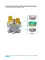
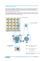
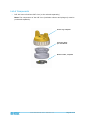
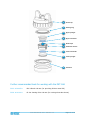
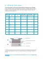
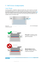
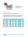
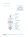
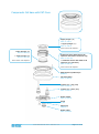
User Manual Release 2.0 Electrochemical Test Cell PAT-Cell 05. October 2015 © 2015 EL-CELL GmbH The information in this manual has been carefully checked and believed to be accurate; however, no responsibility is assumed for inaccuracies. EL-CELL GmbH maintains the right to make changes without further notice to products described in this manual to improve reliability, function, or design. EL -CELL GmbH does not assume any liability arising from the use or application of this product. EL-CELL GmbH Tempowerkring 8 21079 Hamburg - Germany phone: +49 (0)40 790 12 733 fax: +49 (0)40 790 12 736 e-mail: [email protected] web: www.el-cell.com User Manual PAT-Cell – Release 2.0 Page 2 of 19 Content 1 Product Description ............................................................................................ 4 2 Features ........................................................................................................... 7 3 Safety Precautions ............................................................................................. 7 4 Unpacking ......................................................................................................... 7 5 Cell Assembly .................................................................................................... 9 6 Different Test Cases .......................................................................................... 11 7 PAT-Core Components ....................................................................................... 12 9 Disassembly and Cleaning .................................................................................. 15 10 Consumables ................................................................................................... 15 11 Spare Parts .................................................................................................... 16 12 Technical Support ........................................................................................... 18 13 Warranty ........................................................................................................ 19 User Manual PAT-Cell – Release 2.0 Page 3 of 19 1 Product Description The PAT-Cell is the new leadless housing of the PATCore. Two different docking stations are available: the PAT-Single-Stand and the PAT-Tray accommodating up to 16 PAT-Cells. Its small footprint make this combination the ideal choice for high-throughput testing of Li-ion battery materials. PAT-Tray and PATSingle-Stand are covered by separate manuals (http://el-cell.com/downloads/downloads-manuals). PAT-Tray with 16 PAT-Cells The PAT-Core is comprised of three components: 1. Insulation sleeve: The polypropylene insulation sleeve with a ring-shaped reference electrode and a separator, both pre-installed at the factory, sealed and ready for use in the glovebox. Several different versions are available for special purposes. The insulation sleeve is also available in the disassembled state, so that the customer can use his own separator or reference . 2. Lower plunger: The lower plunger serves as the positive current collector. Different gap sizes are available to match electrodes and separators with different thicknesses. When using the proper gap size, the lower electrode can have a maximum thickness of 800 µm. 3. Upper plunger: The upper plunger serves as the negative current collector. The maximum thickness of the upper electrode is 800 µm. Note that the spring force applied on the cell stack will depend slightly on the thickness of the upper electrode. Spring force in relation to the thickness of the upper electrode: 56 Spring force applied on cell stack / N 54 52 50 48 46 44 42 40 0 200 400 600 800 1000 Thickness of upper electrode / µm User Manual PAT-Cell – Release 2.0 Page 4 of 19 The insulation sleeve is a single-use component, which has to be disposed after use. In contrast, the plungers are available as both single -use components (made of battery grade copper and aluminium) and as reusable components (made of stainless steel 316 L/ 1.4404). Other materials are available on request. Upper plunger Insulation sleeve Lower plunger PAT-Cell PAT-Core User Manual PAT-Cell – Release 2.0 Page 5 of 19 Electrical Contacts of the PAT-Cell and Interfacing with the PAT-Tray and PAT-Single-Stand The PAT-Cell is a leadless 3-electrode test cell, so it does not feature any sockets where cables may be plugged into. Instead, the electrical connection towards the battery tester is made through contact areas at the cell bottom, once the PAT -Cell is inserted into one of the sockets of the PAT-Tray. The detail view below shows the contact areas at the cell bottom (on the right), and the corresponding spring-loaded contact pins in the cell socket of the PAT-Tray. The same cell socket is used with the PAT-Single-Stand. PAT-Tray from top PAT-Cell from below R R 1S 1 2/2S PAT-Single-Stand from top 1 2 1/1S: upper electrode (negative), current and sense 2/2S: lower electrode (positive), current and sense R: 2/2S reference electrode The 5 pins in the center are for cell detection andspecial (future) functions. User Manual PAT-Cell – Release 2.0 Page 6 of 19 2 Features The PAT-Cell is a test cell to accurately characterize aprotic lithium-ion battery materials over long periods of times. The standard PAT-Core is composed of a lithium metal ring reference and a separator (either glass fiber or a nonwoven polyester pasted with Al 2 O 3 ). Both the reference and the separator are pre-installed in a single-use insulation sleeve. This concept has got several advantages: Ability for conducting long-term measurements with a reliable reference electrode over more than one thousand hours of battery operation . Ability for measuring full AND half cell impedance spectra throughout the battery’s life time. Increase of testing productivity by single -use concept. Less mistakes that may result from corrosion or cross-contamination when working with re-use cell components. No need for cleaning or drying cell components. Fast assembly and dismantling lowers lead times of experiments. Easy and reliable electrolyte filling upon assembly (defined electrolyte volume down to 0.05 cm³). Reliable leakage-proof sealing with PE-Seal and double cutting ring. Reproducible and homogeneous mechanical pressure on electrodes . High precision 18 mm diameter sandwich geometry with a concentricity better than 0.1 mm (electrode and separator dimensions are compatible with other test cells of the ECC series). The PAT-Cell is designed for use in the temperature range from -20 to +70°C. 3 Safety Precautions Use proper safety precautions when using hazardous electrode materials and electrolytes. Wear protective glasses and gloves to protect you against electrolyte that may accidentally spill out during disassembly. Upon cell disassembly, dispose all materials properly. Metallic lithium and some insertion compounds may decompose heavily in contact with water and other solvents, and can cause fire. 4 Unpacking Check the contents of the packages against the list given below to verify that you have received all of the required components. Contact EL-CELL, if anything is missing or damaged. NOTE: Damaged shipments must remain within the original packaging for freight company inspection. User Manual PAT-Cell – Release 2.0 Page 7 of 19 List of Components: PAT-Cell test cell without PAT-Core (to be ordered separately) Note: The components of the PAT-Core (insulation sleeves and plungers) must be purchased separately. Screw cap, complete Cell base (PAT), pre-assembled Button holder, complete User Manual PAT-Cell – Release 2.0 Page 8 of 19 5 Cell Assembly This section describes how the PAT-Cell has to be assembled in order to conduct proper battery tests. Please note that the assembly has to take place under the protective atmosphere in a glove box. 1. Put the insulation sleeve (6) onto the worktop with the smaller side pointing upwards. Different insulation sleeves are available for different test purposes, see chapters 6 and 7. 2. Insert the lower electrode (7) into the sleeve with the active layer facing downwards. 3. Attach the lower plunger (8). The lower plunger is available in different gap sizes in order to account for the thickness of the electrodes and separator used, see chapters 6 and 7. 4. Turn the assembly upside down. 5. Align the contact spring of the sleeve with the horizontal contact pin inside the cell base (9). Then insert the assembly into the cell base . 6. Evenly dispense approx. 100 µL of electrolyte (5) on top of the separator with a pipette. Note: The optimum amount of electrolyte will depend on the thickness and porosity of the separator and the electrodes used. 7. Insert the upper electrode (4) into the insulation sleeve with the active layer facing downwards. 8. Attach the upper plunger (3). 9. Attach the screw cap (1) to the cell base with the wing nut fully released. 10. Tighten the wing nut clockwise in order to seal the cell. 11. Attach the cell into a free socket of the PAT-Tray. 12. The EC-Link software will detect the cell and ask you to start the measurement. Follow the instructions. 13. Start the electrochemical test of the associated battery tester channel. Operation of the PAT-Tray and the interplay with the connected battery tester are described in more detail in the manual of the PAT-Tray (http://el-cell.com/downloads/downloads-manuals). NOTE: We recommend replacing the sealing ring attached to the lid inside the screw cap right after cell disassembly. User Manual PAT-Cell – Release 2.0 Page 9 of 19 1 Screw cap 2 Sealing ring 3 Upper plunger 4 Upper electrode 5 Electrolyte 6 Insulation sleeve 7 9 Lower electrode 8 Lower plunger 9 9 Cell base Further recommended tools for working with the PAT-Cell: ECC1-02-0005-A ECC-LiPunch 18 mm (for punching lithium metal foil) ECS1-00-0100-A EL-Cut Cutting Pliers 18 mm (for cutting electrode sheets) User Manual PAT-Cell – Release 2.0 Page 10 of 19 6 Different Test Cases The PAT-Core may be used for many different battery and capacitor types. The table below summarizes some of the most common test cases. In general, we recommend sleeves with built-in glass fiber separator rather then thin technical separators (such as Viledon or Celgard) when lithium metal is used as the negative electrode, and when measuring half cell impedances. Battery Lower electrode (+) Upper electrode (-) Lower plunger Upper plunger single-use/re-use single-use/re-use Li-metal LCO, NCA, NCM or LFP Li Al/SS Cu/SS GF Li-metal Graphite or silicon Li Cu/SS Cu/SS GF Li-metal LTO Li Al or Cu/SS Cu/SS GF Li-ion LCO, NCA, NCM, or LFP Graphite Al/SS Cu/SS GF or thin Li-ion LFP LTO Al/SS Al or Cu/SS GF or thin EDLC AC AC Al/SS Al/SS GF or thin Li-ion cap AC Lithiated graphite Al/SS Cu/SS GF or thin Type Separator Upper plunger Ring-shaped reference electrode Insulation sleeve Lower plunger The lower electrode can have a thickness of up to 800 µm provided that the proper gap size of the lower plunger is chosen. The maximum thickness of the upper electrode is 800 µm. User Manual PAT-Cell – Release 2.0 Page 11 of 19 7 PAT-Core Components Lower Plunger: The lower plunger is available in different materials (SS 1.4404, Al 99.5%, Cu 99.9%) and with different gap sizes. The different gaps are necessary in order to account for the different thicknesses of the lower electrode and the separator used. The term ‘gap’ refers to the distance between the lower face of the built-in separator (thought of as having zero thickness) and the upper face of the lower plunger when attached to the insulation sleeve, see sketch below. Gap If you use a wrong plunger gap, you may get trouble with your battery test. The below figures illustrate this point. Good case: No bending of builtin separator; reference ring is in plane with separator. Gap too large: Excessive downward bending of built-in separator; reference ring is out of plane with separator. User Manual PAT-Cell – Release 2.0 Page 12 of 19 Gap too small: Excessive upward bending of built-in separator; reference ring is out of plane with separator. Available lower plungers: The lower plunger is available with gap sizes between 50 and 800 in steps of 50 µm. For ordering, just append the step size to the article code, see table below. For lower electrodes having a thickness of around 100 µm, we recommend a gap size of 100 when using thin separators such as Viledon or Celgard, and a gap size of 200 when using our standard glass fiber separator. In general, for glass fiber, the gap size must be approx. 100 µm larger than the electrode thickness because of the compression of the built-in separator. Gap of lower plunger (in µm) 50 100 150 200 .. 800 Article code lower plunger (SS) ECC1-010027-C_50 ECC1-010027-C_100 ECC1-010027-C_150 ECC1-010027-C_200 ECC1-010027-C_800 Article code lower plunger (Al) ECC1-010027-A_50 ECC1-010027-A_100 ECC1-010027-A_150 ECC1-010027-A_200 ECC1-010027-A_800 Article code lower plunger (Cu) ECC1-010027-B_50 ECC1-010027-B_100 ECC1-010027-B_150 ECC1-010027-B_500 ECC1-010027-B_800 User Manual PAT-Cell – Release 2.0 Page 13 of 19 Upper Plunger: The upper plunger is available in different materials: Stainless steel 1.4404, Al 99.5% and Cu 99.9%. Other materials on request. type of utilization article no. upper plunger (single-use vs. reusable) copper single-use ECC1-01-0026-A single-use ECC1-01-0026-B reusable ECC1-01-0026-C Cu 99.9 (E-CU 58) aluminium Al 99.5 (EN-AW- 1050) stainless steel 316L (1.4404) Insulation sleeve: The insulation sleeve is available with and without a ring-shaped lithium metal reference ring, and with two different types of separator: borosilicate glass fiber separator (Whatman GF/A) having a thickness of 260 µm, and nonwoven polyester pasted with Al 2O3 (Freudenberg Viledon FS 3005-25) having a thickness of 25 µm. Other separators and customized solutions are available on request. Furthermore, the sleeve is available in the disassembled state, either with or without the lithium reference ring. The table below comprises the four standard versions only. article no. type of testing (2 or 3 electrodes) Insulation sleeve ECC1-00-0210-O/x with lithium metal ring reference, with glass fiber separator (260 µm) Insulation sleeve 3 electrodes ECC1-00-0210-A/x with lithium metal ring reference, with Viledon separator (25 µm) Insulation sleeve ECC1-00-0210-P/x with glass fiber separator (260 µm) 2 electrodes Insulation sleeve ECC1-00-0210-B/x with Viledon separator (25 µm) User Manual PAT-Cell – Release 2.0 Page 14 of 19 9 Disassembly and Cleaning After disassembly, dispose all single-use components and electrodes properly. If the cell base has got contaminated with electrolyte, clean it with plenty of water and dry with compressed air. Use less electrolyte for subsequent tests. Plungers made of stainless steel have to be cleaned with plenty of water. If necessary, remove persistent dirt with aqueous nitric acid (20%, 2 hours at room temperature). All other cell components are for immediate re-use without cleaning. 10 Consumables Plunger (single-use): Upper plunger (Al) ECC1-01-0026-B Upper plunger (Cu) ECC1-01-0026-A Lower plunger (Al), gap x = 50 to 800 Lower plunger (Cu), gap x = 50 to 800 ECC1-01-0027-B_x ECC1-01-0027-A_x Insulation sleeves (single-use): Insulation sleeve with Li-reference ring and Viledon separator ECC1-00-0210-A/x Insulation sleeve with Viledon separator only ECC1-00-0210-B/x Insulation sleeve with Li-reference ring and glass fiber separator ECC1-00-0210-O/x Insulation sleeve with glass fiber separator only ECC1-00-0210-P/x Seals (single-use): Sealing ring (lid) ECC1-00-0232-A User Manual PAT-Cell – Release 2.0 Page 15 of 19 11 Spare Parts Components screw cap: Jackshaft (PAT) ECC1-00-0054-C Set screw N_915 Screw cap (PAT) ECC1-00-0225-D Set screw N_913 Screw cap bottom (PAT) ECC1-00-0225-C Retaining ring ECC1-00-0243-A O-Ring DIC9005 Lid inset – w/o thread ECC1-00-0231-B Disc spring lid ECC1-00-0233-A Sealing ring ECC1-00-0232-A Compression spring (Au) FED9028 User Manual PAT-Cell – Release 2.0 Page 16 of 19 Components Cell base with PAT-Core: Upper plunger (SS) ECC1-01-0026-C or Upper plunger (Cu) ECC1-01-0026-A more version see chapter 7 Lower plunger (SS) ECC1-01-0027-C_x Insulation sleeve with built-in GF separator and with Li-reference ring ECC1-00-0210-O/x or Lower plunger (Al) ECC1-01-0027-A_x more version see chapter 7 or Insulation sleeve with built-in GF separator (no reference) ECC1-00-0210-P/x more version see chapter 7 DIN7 A1.5x4 cylindrical pin NRM0013 Cell base (PAT) ECC1-00-0234-A Contact pin – long, assy ECC1-00-0242-B Contact pin – short, assy ECC1-00-0242-A Button holder ECC1-00-0247-B Screw N_965 Shaft ring FED9029 Button (PAT) ECC1-00-0253-A User Manual PAT-Cell – Release 2.0 Page 17 of 19 Plunger (reusable): Upper plunger (SS) (to be ordered separately) ECC1-01-0026-C Lower plunger (SS), gap x = 50 to 800 (steps of 50) (to be ordered separately) ECC1-01-0027-C_x 12 Technical Support Technical support for this product is exclusively provided by EL-CELL GmbH. EL-CELL GmbH Tempowerkring 8 21079 Hamburg - Germany phone: +49 (0)40 790 12 733 fax: +49 (0)40 790 12 736 e-mail: [email protected] web: www.el-cell.com User Manual PAT-Cell – Release 2.0 Page 18 of 19 13 Warranty For a period of one year from the date of shipment, EL -CELL GmbH (hereinafter Seller) warrants the goods to be free from defect in material and workmanship to the original purchaser. During the warranty period, Seller agrees to repair or replace defective and/or nonconforming goods or parts without charge for mate rial or labor, or, at the Seller’s option, demand return of the goods and tender repayment of the price. Buyer’s exclusive remedy is repair or replacement of defective and nonconforming goods, or, at Seller’s option, the repayment of the price. Seller excludes and disclaims any liability for lost profits, personal injury, interruption of service, or for consequential incidental or special damages arising out of, resulting from, or relating in any manner to these goods. This Limited Warranty does not cover defects, damage, or nonconformity resulting from abuse, misuse, neglect, lack of reasonable care, modification, or the attachment of improper devices to the goods. This Limited Warranty does not cover expendable items. This warranty is void when repairs are performed by a non-authorized person or service center. At Seller’s option, repairs or replacements will be made on site or at the factory. If repairs or replacements are to be made at the factory, Buyer shall return the goods prepaid and bear all the risks of loss until delivered to the factory. If Seller returns the goods, they will be delivered prepaid and Seller will bear all risks of loss until delivery to Buyer. Buyer and Seller agree that this Limited Warranty shall be governed by and construed in accordance with the laws of Germany. The warranties contained in this agreement are in lieu of all other warranties expressed or implied, including the warranties of merchantability and fitness for a particular purpose. This Limited Warranty supersedes all prior proposals or representations oral or written and constitutes the entire understanding regarding the warranties made by Seller to Buyer. This Limited Warranty may not be expanded or modified except in writing signed by the parties hereto. User Manual PAT-Cell – Release 2.0 Page 19 of 19