1
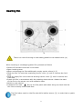
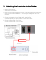
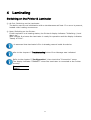
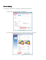
User Manual
Laminator L201
Website: www.teamnisca.com
Email: [email protected]
Version: L201-K12/V0.03
1
Table of contents
1. General information........................................................................ .
Product description...............................................................
Symbols and conventions......................................................
Intended use.......................................................................
Safety information................................................................
Environmental information.....................................................
2. Connection and commissioning......................................................
Device overview...................................................................
Unpacking and setting up the device.......................................
Connecting the device...........................................................
Connecting to the power supply...........................................
Connecting to the PR-C201 printer.......................................
Connecting to a computer...................................................
Inserting film.......................................................................
3
3
3
4
4
5
6
6
7
8
8
8
8
9
3. Attaching the Laminator to the Printer............................................
10
4. Laminating......................................................................................
11
Switching on the Printer & Laminator…………………………………………
Driver Setting…………………………………………………………..………………….
Laminating Action……….……………………………………………………………….
5. Configuration..................................................................................
11
12
14
15
Menu Route Map (Laminator Setup)....................................... 15
Configuration settings.......................................................... 16
6. Troubleshooting.............................................................................
19
Types of errors and elimination............................................. 19
Error messages................................................................... 20
7. Service...........................................................................................
22
Firmware upgrade............................................................... 22
8. Specification...................................................................................
23
L201 Heat Roller Unit............................................................. 23
2
1
General information
Product description
See specification!
Symbols and conventions
The following symbols and conventions are applied in this user manual.
The symbol indicates important information, which must be observed. A failure to do so
may lead to injuries.
The symbol indicates parts of the device that are hot and should not be touched.
Good advice or information regarding important working steps.
Framed text corresponds with a key on the Printer’s control panel.
3
Intended use
The device is constructed in accordance with the latest engineering practice and per the
recognised safety regulations. Nevertheless, danger to the life and limb of the user or third
parties or damage to the device and other property may occur when using it.
The device must be operated exclusively when in a technically faultless condition, as
intended, with an awareness of safety and potential hazards, and in accordance with the
operating manual.
The device is intended exclusively for laminating suitable materials. Any other use or any use
exceeding this is considered unintended use. The manufacturer shall not be liable for any
damage that results from misuse. The operator is solely responsible for the resultant risk.
Safety instructions
The device is designed for an AC mains supply from 100 V to 240 V. It must be
connected exclusively to sockets with a grounded conductor contact.
The device must be operated exclusively in a dry environment and must not be
exposed to any moisture (spray, mist, etc.).
Do not operate the device in potentially explosive atmospheres.
Do not operate the device in close proximity to high voltage lines.
If the device is operated with an open cover then it is essential to ensure that
clothing, hair, jewellery and similar personal effects cannot come into contact
with the exposed, rotating parts.
The device or parts of it may become hot during lamination. Do not touch during
operation and allow to cool prior to changing the film if necessary.
Risk of crushing when locking the heated rollers or closing the cover.
Only execute the actions described in this user manual. Further work must be
carried out exclusively by trained personnel or service technicians.
Unprofessional intervention or modifications to the device may endanger
When opening the housing cover a risk of death exists due to live parts.
4
Environmental information
The device comprises materials that can be reused when processed by specialist recycling
companies. The optimum design of the laminator facilitates a straightforward separation of
the recyclable materials. Label the device as scrap and dispose of it in accordance with the
legal regulations.
5
2
Connection and commissioning
Device overview
2
1
4
1 Carrier roller
2 Spacer ring
3 Heated roller
4 RFID module
6
2
1
Unpacking and setting up the device
•
•
•
Remove the device from its packaging and place on a level surface.
Check the laminator for transport damage.
Check delivery for completeness.
Scope of supply:
• Laminator
• Power adapter
• Mains cable
Store original packaging for subsequent transportation.
7
Connecting the device
Connecting to the power supply (24V connection jack)
The laminator is equipped with a external broad-range power pack for a mains
voltage of 100 V to 240 V. Plug the mains cable into an earthed socket and the
24V cable into the 24V device connection jack.
Connecting to the PR-C201 Printer (RS232-Interface)
The laminator must be connected to the PR-C201 printer with a suitable interface cable.
(Refer to the chapter 3 “Attaching the Laminator to the Printer”)
Connecting to a computer (RS232-Interface)
For configuration and service purposes the laminator must be connected to the
computer with a suitable interface cable. (Refer to the chapter 7 “Service”)
8
Inserting film
There is a risk of burning on the safety guard for the heated roller (4)
When inserting or exchanging patch film proceed as follows:
•
•
•
•
•
•
•
•
Switch off the device and let it cool down
Open housing cover
When exchanging the film additionally empty carrier rollers (1,2)
Slide the film roll onto the unwinding carrier roller (1) until it reaches the limit
stop.
Slide an empty film core onto the winding carrier roller (2) until it reaches the
limit stop.
Insert the film in accordance with the drawing shown above. Attach the start
of the film to the empty core with adhesive tape.
Switch on the device.
Transport film with
key to the first patch and when doing so check that the
film runs correctly and crease-free.
The first index mark on the film should lie before sensor (3), in order that no patch
is lost.
9
3 Attaching the Laminator to the Printer
① Switching off the Printer.
Switching off the Laminator.
② Insert the hooks of the Laminator to the holes by the Card Ejection Slot of the Printer.
Insert the hooks of the Card Stacker to the holes by the Card Ejection Slot of the
Laminator.
③ Connect the Laminator with the Printer via the serial interface.
A standard cable RS-232 SERIAL SUB D9 connector jack is used.
④ Connect the Power Cable of the Printer.
Connect the Power Cable of the Laminator.
<Printer>
RS-232C cable
<Laminator>
10
4
Laminating
Switching on the Printer & Laminator
① At first, Switching on the Laminator.
The device carries out initialization with a simultaneous self-test. If no error is present,
heated roller heating commences.
② Next, Switching on the Printer.
If the Laminator is at heating status, the Printer’s display indicates “Initializing / Lami
Warm up”.
After roughly 8 minutes the Laminator is ready for operation and the display indicates
“Ready to Print”.
It is assumed that Laminator’s film is already present inside the device.
Refer to the chapter 6 “Troubleshooting” when Error Message was indicated.
Refer to the chapter 5 “Configuration”, then check the “Connection” menu.
The display indicates “CONNECT” when the Laminator is connected to the Printer
correctly.
Connection
CONNECT
11
Driver Setting
For laminating, check the box of “Lamination” in the PR-C201 Printer Driver.
① Select “General” tab, and click “Preferences…”
② In case of laminating front side, select “Graphics” tab and check “Lamination”.
12
③ In case of laminating back side, Select “Graphics(back)” tab and check “Lamination”.
“Graphics(back)” tab will be appeared only when "Duble Side Printing" was selected.
13
Laminating Action
With checking "Lamination" of the Printer Driver, It processes laminating after having
performed each processes of printing, magnetic & IC encoding.
When the Laminator is connected to the Printer, The card is outputted from Card
Ejection Slot of the Laminator, regardless of “Normal Exit” setting .
When the Laminator is connected to the Printer, The card is outputted with its last
laminating surface upwards, regardless of “Exit Face” setting.
14
5
Configuration
Menu Route Map (Laminator Setup)
The different setting options configure the laminator for specific requirements. This
is carried out via the Printer’s control panel
Refer to the PR-C201 Operation Guide for the control of the control panel.
Mode Select
[Option Mode]
Magnetic Encoder
SET:>>
IC R/W 1
SET:>>
IC R/W 2
SET:>>
External Box
SET:>>
RS-232C Setup
SET:>>
Laminator Setup
SET:>>
15
Connection
CONNECT
Version
************
SerialNumber
************
TagInfo
##
Foil Type
PATCH
Temperature
150
Lamination Speed
6
Delay (x10)
20
Cool Down Time
0
LaminationLength
86
FoilFurtherMove
14
Foil Position
0
Standby
OFF
①
②
③
④
⑤
⑥
⑦
⑧
⑨
⑩
⑪
⑫
⑬
Configuration settings
① Connection
Showing the connection of the Laminator.
Connecting:CONNECT
Disconnecting:DISCONNECT
② Version
Showing the firmware version.
③ Serial Number
Showing the serial number of board.
④ Tag Info
Showing the 8-digit tag information.
⑤ Foil Type
Setting the film type.
Setting range:
Patch : Patch (always with black marking)
HOLO(INDEX) : Thin film with black marking
HOLO(NO INDEX) : Thin film without black marking
The difference between patch and thin film with black marking is another
lamination position of the card.
⑥ Temperature
Setting the thermal energy for the heated roller for lamination. The correct
temperature must be experimentally determined with consideration to the
lamination speed, the film and the plastic card. The presetting must be considered
a guideline value.
Setting range:
120...150...180 degree C
16
⑦ Lamination Speed
Setting of the transport speed of the document during lamination. The correct
speed must be experimentally determined with consideration to the lamination
temperature, the laminate film and the plastic card. The presetting must be
considered a guideline value.
In order to carry out a test it is possible to start the motor via
Setting range:
4...6...20 mm/s
⑧ Delay (x10)
Setting the waiting time, once the heated roller has lowered and lies on the
document. Only after this time does the actual lamination start.
Setting range:
LCD
0
1
…
20
…
200
Delay (ms)
0
10
…
200
…
2000
⑨ Cool Down Time
After settled cooling time, the status will be set to INPOS. Time is start after card
is in park position and ready to eject to the printer.
Setting range:
0...60 s
⑩ Lamination Length
Setting the lamination range.
Setting range:
80...86...100 mm
⑪ Foil Further Move
Setting the foil further move. This parameter is important to separate the foil after
lamination from the card.
Setting range:
10...14...30 mm
17
⑫ Foil Position
With a change in the plastic card intake range, precise placement of the film is
carried out.
With an enlarging of the intake range, the lamination of the plastic card starts
later. Conversely, with a reduction in the intake range lamination starts earlier.
The direction arrows on the display indicate the direction of travel once lamination
starts.
Setting range:
-30...0...+30 x 1/10mm
⑬ Standby
If the laminator is not used for 30 minutes it switches to energy-saving mode.
The temperature of the heated roller drops in this mode. Press [SET] or sent a
Print job to finish. Also a card in entrance position stops standby state.
The energy-saving mode must be active for this option!
Setting range:
OFF
Standby off
ON
Standby on
18
6
Troubleshooting
Type of errors and elimination
If an error occurs then this is signaled by the red ERROR LED whilst the error
message is shown on the printer’s display. Different error codes indicate the cause
of the problem.
"Rectifiable errors" are usually film or transport errors, which are simple to
remedy.
In a normal case it is possible to recover the error after eliminating the problem and pressing
[SET] key, after which the device is once again ready for operation.
"Non-rectifiable errors" are triggered by defective hardware. If a restart does not
solve the problem then service intervention is necessary.
In the event of a "system error" the device must be returned to the factory.
19
Error messages
Cause
Error Massage
Service
Service
Service
Service
Service
Service
Service
Service
Service
Service
Service
Service
Service
Service
Call
Call
Call
Call
Call
Call
Call
Call
Call
Call
Call
Call
Call
Call
Lami Tag Error
Service Call
/
/
/
/
/
/
/
/
/
/
/
/
/
/
C0-01
C0-02
C0-03
C0-04
C0-05
C0-06
C0-07
C0-08
C0-09
C0-10
C0-11
C0-12
C0-13
C2-15
/ C3-53
Remedy
Invalid communication between
the Printer and the Laminator.
Contact service!
Invalid control error.
Invalid tag information with initial
Use permissible / approved film
acquisition of the film.
material.
/ C8-54
Error message from tag reader.
Reader:Communication Error
Indicates signal between reader
and tag too weak. Visual
inspection!
Service Call
/ C8-55
Reader transfer error. Contact
Check connection cable
problems between board and tag (service)
reader
Lami Tag Error
/ C3-56
No response from tag reader.
Use permissible / approved film
Tag not seen or not read.
material.
Card Lami Remove / C4-61
Card
Card
Card
Lami
Jam Lami
Jam Lami
Jam Lami
Film End
/
/
/
/
C5-62
C5-63
C5-64
C6-65
Transport of the document failed.
Film end
Remove document from the
transport tray manually.
Insert new film
Synchronization of the film failed. - Insert film with index marks -
Lami Film Error
/ C7-66
Insert film correctly - Configure
correct film type
Lami Film Error
/ C7-67
No film transport.
20
Check film
Error Massage
Service Call
/ C8-81
Cause
Remedy
No response from tag reader.
Check tag reader. Contact
service!
Service Call
/ C8-82
Impermissible ADU values
Check temperature sensor.
Contact service!
Service Call
/ C8-83
No temperature increase to
Check temperature sensor.
record
Contact service
Service Call
/ C8-84
Heated roller not in limit position
Contact service!
Service Call
/ C8-85
Circuit breaker for high
Contact service!
temperature has triggered.
Service Call
/ C8-86
Both sensors in transport tray
Check transport tray, otherwise
see document
Contact service!
Service Call
/ C8-98
No access to the EEPROM
Contact service!
Service Call
/ C8-99
Electronic type plate missing
Contact service!
21
7 Service
Firmware upgrade
For service purposes the laminator is connected with the computer via the serial
interface. A standard cable RS-232 SERIAL SUB D9 connector jack is used.
After starting the Windows application AVR-Bootloader it is possible to load new
firmware. Prior to this the interface agreements as well as the path for the
access to the application code (*.HEX) must be stipulated
The download process can be started as follows:
• Switch on laminator
• Press „Jump to Bootloader then Download“
22
8 Specification
L201 Heat Roller Unit
Lamination Method
Lamination Area
Ribbon Dimensions
Card Dimensions
Black Marking
Card Movement
Card Recognition
Ribbon Control
Speed Range
Temperature Range
Interface Connection
Casing
Hardware Connection
Power Supply
Output
Environmental
Hot Roller, with Temperature sensing at the surface of the Roll
Full card thin film lamination
Patch Lamination 82 x 50 (mm)
60 mm in width
250 patches or total of 60 mm outside diameter
ISO CR-80 size
Adopted to the existing ribbons
Bidirectional, to allow dual sided lamination (using Flipper inside
the printer)
Detected at Laminator entrance to take over the card coming out
of printer
Movement and Originality of ribbon is controlled
2 - 18 mm/sec
100 – 180 ℃
Serial communication to the printer using the special protocol
Metal Casing
Hanging mechanism to easy hanging to the printer
Unit is mechanically adopted to the PR-C201
Input range 100 – 240 v/47 – 63Hz
24v, 3.75A
Min/Max operating temperature: 15 – 30 ℃
Humidity: 20 – 65% non-condensing
Min/Max storage temperature: -5/70 ℃
Storage humidity: 20 – 70%, non-condensing
Operating ventilation: free air
23