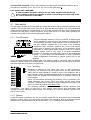
1
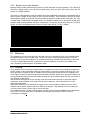
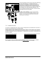
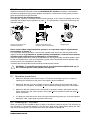
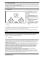
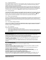
B
TA 600
USER MANUAL
8. Gain switch channel A. Three of the switches in the DIP-switch selects the maximum gain of
the channel to be either 20, 23, 26, 29, 32, 36, 39 or 41 dB. (See page 6).
9. AC power cable. WARNING!
A label just below the mains cable on the rear of the amplifier indicates the AC
mains voltage, for which the amplifier is wired. Connect the power cable only to the
AC source referred to on the label.
!
5 REAR PANEL FEATURES
5.1 Gain switch
The gain switch located on the rear panel (the central DIP-switch) changes the input sensitivity of the
amplifier. This can be handy when using low or high nominal input signals. E.g. most professional
mixing consoles operate at a nominal level of +4 to +6 dBu; therefore you may use the 32dB position
to provide you with plenty of fader movement. On the other hand, for a disco mixer operating at a
nominal level of 0dBu or less use the higher gain positions.
5.1.1 The DIP-switch
There are separate sections for the two channels, so different gain
can be selected for channel A or B. The selection of maximum gain
in the amplifier is always a trade between noise and headroom. A
low gain amplifier amplifies less of the noise of the preceding
equipment (mixer, crossover, equalizer etc.). On the other hand a
higher lever is needed to get full power, so the headroom will be
decreased on mixer output and/or crossover units. In an actively
divided system there is very often a so-called loudspeaker
processor or controller involved, being unique for the loudspeaker
system. In most cases the manufacturers of these processors
and/or loudspeakers recommend a specific system gain for the
amplifiers.
There are eight positions with different gain, from 20dB to 41dB in 3dB steps. See the different
settings for the DIP-switches in the table below. The three switches to the very left are for channel B,
and the three to the very right are for channel A.
5.1.2 Sensitivity
Sensitivity is defined as how many volts (rms) or dBu (referred to
0.775Vrms) are required to get full output power. As the output power
varies with the load impedance, usually 4 ohms is the reference. But in
case of an MLS-switch equipped amplifier there are enough choices for full
output levels into different load impedances for a sensitivity table to fill
several pages.
Hence we recommend calculating the sensitivity if this is necessary. Our
”Audio calculator” can do this, which is an Excel file with many useful
formulas. It contains help for setting up digital loudspeaker processors and
can be found on our website www.tannoy.com
The sensitivity calculator is found in the box labeled “Amplifier gain
conversions”. The values to enter are in red; desired output power (see MLS-table), load
impedance and the selected maximum gain. The sensitivity is in the box labeled “Input level for
clip” in Vrms or dBu.
5.1.3 Options
As the DIP-switch is recessed, one can put a sticker across the bay and prevent from unauthorized
changes. Another option is to remove the DIP-switch. This should be done by authorized service
personnel only! This corresponds to all switches set to “off”, i.e. 32dB gain and stereo mode.
Tannoy Limited
TA 600 User Manual 06-12-02
6
5.2 Link switch
The Link switch located on the rear panel (the central DIP-switch) is for changing the operation mode
of the amplifier (see below, section 5.3).
5.3 Operation modes
5.3.1 Stereo mode
In this mode, both channels operate independently of each other. This is used for
all 2-channel modes, such as stereo and bi-amping. Set the two center switches to
off position for the stereo mode. The level attenuators on the front panel will
control the respective channels levels.
Never connect either output terminal to ground or in parallel. The
recommended minimum nominal impedance, for stereo or tandem operation, is 2
ohms per channel.
5.3.2 Note for bench test
NOTE: Channel B is always polarity reversed on the input, but polarity compensated
by feeding the minus pin on the Channel B output with the output voltage. Channel A
output is connected in normal polarity mode. By having channel A and B operating in
opposite polarity, the energy storage in the power supply is more efficient. This is significant
for signals below 100 Hz (sub bass etc.) and improves the power bandwidth. Be sure to use
balanced inputs on all measurement equipment (also oscilloscope probes) if you are
bench testing.
!
Reverse operation of Channel B.
5.3.3 Tandem mode
In tandem mode both channels' inputs are linked and receive the same signal. The tandem mode
is active if the Link switches are in position "On". Both level attenuators are active, allowing you to
set different levels for each channel. Note that only the inputs are connected in parallel. This is
NOT a parallel output mode. Never connect either output terminal to ground or in parallel.
You can use the remaining input connectors to carry signal to other amps. This is called “Daisychaining”.
NOTE: Always turn off the Link switch when using the amplifier for Bi-amping.
5.3.4
Bridge mono mode
Bridge mono mode is used to deliver both channels' power to a single
load. The nominal impedance of the load must be more than 3 ohms.
Set the Link switches to the “On” position and use one of the input
connectors. You can use the remaining input connectors to carry
signal to other amps. Both level attenuators must be at the same
position. We recommend that you put them in the 0dB (full) position.
Connect the speaker as shown. Always use Channel A’s output
connector.
Tannoy Limited
TA 600 User Manual 06-12-02
7
5.3.5 Bridge mono mode features
Bridged mono mode combines the power of both channels into one speaker. This results in
twice the voltage swing, four times the peak power and just less than three times the full
power of a single channel.
One way to understand the load and power from the amplifier’s perspective in bridged mode is
that it is zero voltage at the center of the voice-coil winding. This is because the coil is driven
with positive voltage at one pole and an equivalent negative voltage at the other pole. So, if an
8 ohms load is connected in bridged mode, one channel shares one 4 ohms part of the load,
and the other channel shares the other 4 ohms part. The power into 4 ohms from an TA 600 is
320W. So, the total bridged power into the 8 ohms load will be 2 x 320 = 640W
6 INSTALLATION
6.1 Mounting
The amplifier is two rack units high (2U) and will mount in a standard EIA 19” rack. Amplifiers may
be stacked directly on top of each other. There is no need for spacing between units. If it is the
intention to fill a rack with amplifiers, we recommend racking is started from the bottom of the rack.
It is also recommended that rear supports are used for amplifiers mounted in the middle of the
rack, especially if used as part of a portable system.
6.2 Cooling
Your amplifier uses a forced air cooling system to maintain a low and even operating temperature.
All fan cooled Tannoy amplifiers have front to rear airflow. There are several reasons for this, one
being that there is usually cooler air outside the rack than inside, and therefore the amplifiers can
run at higher continuous power levels without thermal problems. Never try to reverse the airflow, as
the Intercooler® needs a pressure chamber between the fans and heat sink, and this only works in
one direction of the airflow.
Should a heat sink get too hot, its sensing circuit will mute the hot channel. If the power supply
overheats, another sensing circuit will mute all output channels, until it cools down to a safe
operating temperature.
Make sure that there is an adequate air supply in front of the amplifier, and that the rear of the
amplifier has sufficient space to allow the exhaust to escape. If the amplifier is rack-mounted, do
not use covers or doors on the front or rear of the rack.
For installations with a central cooling system, usually found in fixed installations with a dedicated
rack room, it may be necessary to calculate the maximum heat emission. Refer to Power
consumption on page 9.
Tannoy Limited
TA 600 User Manual 06-12-02
8
6.3 Operating voltage
WARNING!
A label just below the mains cable on the rear of the amplifier indicates the AC
mains voltage, for which the amplifier is wired. Connect the power cable only to the
AC source referred to on the label. The warranty will not cover damage caused by
connecting to the wrong type of AC mains.
!
If the power plug is not appropriate for your country, it can be cut off and wired to a suitable
connector in the following way:
BLACK or BROWN
LIVE
WHITE or BLUE
NEUTRAL
GREEN or GREEN/YELLOW
EARTH
Once the AC connector is connected to a suitable AC supply, the amplifier can be started with the
power switch. When you power up the amplifier it takes a couple of seconds to check its circuits (this
is known as the "soft start" or "slow start" sequence), the fans then blow at high speed before going
into "idle" and the two bottom green LED’s come on to show the output circuits are receiving the
correct rail voltage.
6.4 Grounding
There is no ground lift switch or terminal on this amplifier. The signal ground is always floating via a
resistor to chassis and the grounding system is automatic. If a potential above 0.6V presents itself
between signal ground and chassis ground, a short circuit is introduced between the two, thereby
enabling electrical protection. If a unit in the system is faulty, its mains fuse will blow, due to this
automatic ground system.
If however you wish to tie the signal ground to chassis, connect the XLR-connector’s shell lug to pin
1. In the interest of safety never disconnect the earth pin on the AC power cord.
For all units that are CE approved (radio interference), there is an AC mains filter. This filter needs
the chassis ground for reference, otherwise a current loop is formed via the signal ground.
Use the balanced input to avoid hum and interference.
6.5 Power consumption
There are three ways to determine the power/current consumption of the amplifier:
First, the peak current draw at full output power. Under this condition the power will blow the mains
breaker within 30 second and the amplifier will operate for less than 2 minutes before thermally
limiting. During this time, the temperature of the power supply will be stabilised at a temperature
that will have no effect on the insulation rating of the AC line cord.
Second, the maximum expected average current under worst case program material which is 1/3
of full power according to the FTC-standard. At this level the music will be in the state of constant
clip and is therefore the highest power level one can obtain without completely obliterating the
program.
Last, the "normal operating power", as defined by the safety standard IEC 65/ANSI/UL 6500 and
used by a majority of safety agencies. The normal operating power is measured using pink noise,
with an average output power equal to 1/8 of full power. The one eighth of the total power is as
loud as you can play music while making some attempt to avoid obvious clipping. It also
corresponds to headroom of 9dB, which is very low for normal audio program.
Tannoy Limited
TA 600 User Manual 06-12-02
9
MAX OUTPUT POWER
TA 600
note 1
note 2
8 ohms
4 ohms
2 ohms
2x
2x
2x
Power
[W]
200
320
470
MAINS INPUT POWER
1/3 Power
note 1
345
570
930
1/8 Power
note 2
235
370
585
Idle
60
60
60
Average power with music as program source. The amplifier driven to clip level.
Normal music power with 9dB headroom, IEC standard power rating.
Table 1.
6.5.1 Calculation
The current draw can be calculated by dividing the mains input power by the mains voltage.
We recommend you to design the power distribution for at least the current at 1/8 power, and 1/3
power for heavy-duty demands like discos etc.
The heat power can be calculated as in the following example:
We consider headroom of at least 9dB and a 4 ohms load on an amplifier producing 700 watts per
channel. The 1/8 power per channel is accordingly; 320 / 8 = 40 watts, and total output; 2 x 40 = 80
watts.
The power consumption according to the chart above is then 600 watts.
The heat power produced is the difference between the power consumption and output power;
600 - 80 = 520 watts per amplifier.
7 CONNECTIONS
7.1 Input connections
7.1.1 Balanced inputs
XLR Input connectors are active balanced and wired according to the IEC 268, that is pin 2 hot, and
wired in the following way:
PIN 1
PIN 2
PIN 3
GROUND/SHIELD
HOT (+)
COLD (-)
Figure 4. XLR input connector
Figure 5. XLR balanced
Within the Neutrik® Combojack there is a ¼”(6.3mm) phone jack, which is wired in parallel with the
XLR.
TIP
RING
SLEEVE
HOT
COLD
SHIELD/GROUND
Figure 6. ¼” TRS plug
Tannoy Limited
TA 600 User Manual 06-12-02
10
The input impedance is high enough (20 kohms balanced)
to allow ”daisy-chaining”, or multiple parallel input
connections. The headroom of the input circuits is also
high enough to accept the maximum output level from
virtually any low-level signal source. Balanced signals are
less sensitive to AC hum and radio interference. The
source impedance should be less than 1 kohms to avoid
high frequency loss in long cables.
To daisy chain amplifiers, use the screw-terminal
(Phoenix connector), labeled Link, provided on each
channel. It is connected in parallel with the Neutrik®
Combo jack on each input.
7.1.2 Unbalanced inputs
To connect an unbalanced source, tie pin 3 (ring on TRS jack) down to the shield of the connector. If
you leave one pin disconnected, you will lose 6 dB.
A better method for using unbalanced sources is shown in Figure 8. This is similar to the connection
for balanced lines, but pin 3 is connected to the shield at the source. The hum and noise rejection for
the cable is equivalent to that for a balanced line. To minimize hum in the audio, use balanced inputs
whenever possible.
Figure 7. Unbalanced line connection
Figure 8. Balanced line with unbalanced equipment
For two-channel (stereo) operation, use both channels A and B. For tandem stereo or bridged
mono operation, use only one of the inputs. See operation modes for more details.
Tannoy Limited
TA 600 User Manual 06-12-02
11
7.2 Connecting speakers
Speaker connections are made via the two Neutrik® NL4FC Speakon connectors. The Speakon
connector is designed for high power speaker connections. It assures the correct polarity, it locks in
place and prevents from shock hazard.
They are wired in the following manner:
The right jack, Channel A, has both channel A and B outputs, so it’s useful for bridging and bi-amp
operation (see bridged mono operation on page 7). The left Speakon, Channel B, carries only the
channel B output.
Channel A and B into two
separate Speakons.
Channel A and B into one
Speakon (Stereo and Bi-amp)
Bridged mono
Never connect either output terminal to ground or to some other output or input terminal
(see warnings in chapter 1)
For normal two-channel operation, connect each speaker load across the output’s positive and
negative terminals. Pay attention to speaker polarity; loudspeakers connected out of polarity
degrade sound quality and may be damaged as a consequence.
Keep the speaker cable wires as short as possible and use a good quality stranded speaker cable.
Do not use shielded wire, such as microphone or guitar cable. Remember that the speaker cable
robs the power of the amplifiers in two ways:
Increases the load impedance and introduces resistive power losses.
WARNING: To prevent from electric shock, do not operate the amplifier with any of
the conductor portion of the speaker wire exposed.
8 OPERATION
8.1 Operation precautions
•
Make sure that the power switch is set to “off” before connecting any input or output or
operating the switches on rear panel. See pages 8 about installation.
•
Make sure that the AC mains voltage is correct and the same as the one printed on the
rear panel of the amplifier. See pages 9, about operating voltage and power consumption.
•
Make sure that the switches on the rear panel for operation modes, gain-switch and cliplimiter switch are in the correct position. See page 7 about operation modes and page 13
about clip limiters.
•
It is always a good idea to turn down the gain controls during power-up, to prevent speaker
damage in case a high signal is present at the input.
8.2 Powering up – Soft start
When you power up the amplifier it takes a couple of seconds to check its circuits. This is known as
the "soft-start" or "slow-start" sequence. The fans then blow at high speed before going into "idle"
and the two bottom green LED’s illuminate to show the amplifier is operational.
Tannoy Limited
TA 600 User Manual 06-12-02
12
8.3 Input attenuators
The two input level attenuators on the front panel adjust the signal level for their respective amplifier
channel in all modes. They are calibrated in dB to help setting up active loudspeaker systems or
cutting down unwanted noise from the input signal.
In bridged mode, both controls must be in the same position, so that the speaker load will be shared
equally between the channels.
8.4 Indicators
The yellow LEDs at the top indicate
if any protection circuits are
activated. These are described on
page 13.
The Clip/limit indicator tells when
the amplifier output is clipping or
limiting. It has two different indication
statuses:
• If the clip limiter is engaged it has
a short time constant and it
illuminates briefly.
• If the clip limiter is not engaged it
has an increased time constant
and it illuminates for a longer
period.
Front Indicators
The ”-40 dB” LED’s illuminate if the output signal is greater than -40dB (with 0dB as reference to
full output power). These LED’s also act as signal present indicators.
The two bottom green ”ON” LED’s indicate that the output circuits are receiving the correct rail
voltage.
9 PROTECTION FEATURES
Each Tannoy amplifier has many advanced protection features, protecting both the amplifier and the
speakers connected to it should a fault condition arise. Under normal use these features are
inaudible. All protection circuits are independent.
9.1.1 Clip Limiter
The clip limiter is included to prevent dangerous clipped signals reaching the speaker and damaging
it. When an amplifier is severely overdriven, its output waveform is clipped (its peaks are squared off)
–reducing the crest factor. In extreme cases, the waveform can approach that of a square wave. An
amplifier is normally capable of producing far more power under these conditions than its normal
undistorted rated output power.
The limiter works by monitoring the output and comparing the distortion produced between the input
and output of the amplifier. If the distortion exceeds 1%THD for any reason (voltage or current
clipping), the limiter reduces the input signal proportionally. Note that, if the signal is distorted or
clipped before it reaches the amplifier, the clip limiter cannot detect it, and will not be activated.
Under normal operation the clip limiting is inaudible. The limiter can be turned On or Off by
depressing or pressing the relevant clip limit switch.
Some manufacturers of loudspeaker controllers do not recommend the use of clip limiters in
amplifiers, as they tend to upset the tracking of the controller’s limiters.
Apart from this one exception, Tannoy recommend leaving the clip limiters switched "on" (button
depressed). (As a side-effect, once the amplifier comes out of a protect condition, the output level
has a slow rise time -the effect is like turning the gain up slowly).
Tannoy Limited
TA 600 User Manual 06-12-02
13
9.1.2 Thermal protection
If the amplifier is driven very hard into a low impedance load, the cooling fans will run at high speed.
If the causing conditions continue, the Temperature indicator(s) will illuminate indicating that the
amplifier is about to go into thermal shutdown.
After five seconds the amplifier will go into thermal protection by muting the input signal. After 15-20
seconds the amplifier will have cooled down enough for the amplifier to come out of shutdown and
operate as normal. If the load conditions remain unchanged the thermal protection will be reinitiated.
Thermal protection starts when the Intercooler® heatsink reaches a temperature above 900 C.
9.1.3 VHF protection
If a signal above 12kHz is detected at the amplifier outputs for more than five seconds at full output
power, the VHF protection mutes the input signal. (This is indicated on the front panel (2) labeled
Protect). After five seconds the outputs will un-mute and return to normal operation, unless the
output signal has remained unchanged, in which case the VHF protection will re-initiate.
9.1.4 Short circuit protection
All Tannoy amplifiers are completely short circuit protected. The protection circuit permits very high
peak currents, but still holds the output devices within the safe operation area. If a short circuit is
maintained, the channel affected will eventually go into thermal protect cycle until the short circuit has
been removed.
9.1.5 AC mains voltage protection
If the AC mains voltage is over the allowed operational voltage, the power supply will automatically
shut down. Once the mains voltage is above the minimum start voltage and below its maximum
operating voltage the amplifier will restart.
9.1.6 D.C. protection
There are two types of DC protection:
• Fuses on the supply branches of each channel.
• A DC crowbar protection that shorts the output if more than 10 volts DC are being detected
on the outputs. Both these circuits come into effect once a DC level are beeing detected on
either channel.
10 MAINTENANCE
Under normal use the amplifier should provide years of trouble-free service. The only user
maintenance required by the user is to vacuum the front grill periodically.
In some extreme cases it may be necessary for authorized service personnel to clean the inside of
the amplifier. These conditions usually occur after prolonged use, e.g. in environments using
"cracked- oil" smoke machines.
If you are using your amplifier for heavy duty use i.e. concert touring or industrial music it is
recommended that you have your amplifier serviced every 3 years, purely as a preventative
measure.
10.1 Troubleshooting
These are typical things to check if you think your amplifier is faulty:
Fault: No output.
If the Signal Present (-40dB) is illuminating there is nothing wrong with the amplifier; the likely
cause is an unsecured Speakon speaker connector.
Check also that the VHF protection is not activated. If it is, remove possible high frequency
oscillations from the relevant input.
Fault: The amplifier goes into thermal protection when driven at low level.
Check that nothing causes a short circuit at the amplifier's output, e.g. any component in the
loudspeaker (this can occur when the speaker coil gets warm).
Fault: The amplifier goes into protection with power indicators off.
Check that the AC line voltage is within the amplifier’s operating range, 130-265V@ 230V, (65135V @ 115V). Over-voltage protection may have occurred. If the amplifier is connected by
Tannoy Limited
TA 600 User Manual 06-12-02
14
mistake to a 3 phase supply, an internal non-resetable fuse or resistor may have blown. Then
return the amplifier to your supplier for service.
Fault: The amplifier does not respond even after checking above items.
In the unlikely event of on a non-user rectifiable fault, return the amplifier to your supplier or an
approved service centre.
Tannoy cannot be held responsible for damage or injury as a result of the top cover being
removed.
11 WARRANTY
General
This product is manufactured by Tannoy and is warranted to be free from defects in components
and factory workmanship under normal use and service, for a period of one (1) year from the date
of original purchase.
During the warranty period, Tannoy or its nominated agents, will undertake to repair, or at their
option, replace this product at no charge to its owner, when failing to perform as specified,
provided the unit is returned undamaged and shipping pre-paid, to factory or authorised service
facility.
This warranty shall be null and void, if the product is subjected to:
Repair work or alteration by person other than those authorised by Tannoy or its agents.
Shipping accidents, war, civil insurrection, misuse, abuse, operation with incorrect AC voltage,
operation with faulty associated equipment, exposure to inclement weather conditions and normal
wear and tear. Units, on which the serial number has been removed or defaced, will not be eligible
for warranty service.
Tannoy shall not be responsible for any incidental or consequential damages, with respect to the
products warranted.
Tannoy reserve the right to make changes or improvements in design or manufacturing, without
assuming any obligation to change or improve products previously manufactured.
This warranty is exclusive and no other warranty is expressed or implied. This warranty does not
affect your statutory rights.
International
Please contact your supplier for this information, as rights and disclaimers may vary from country
to country.
Technical assistance and services
International
If your Tannoy product needs repair, contact your Tannoy dealer or distributor, or contact Tannoy
by fax or email to obtain the location of the nearest authorized service center.
Factory services
In the event of your Tannoy product needing factory service, you may contact Tannoy’s service
department for return instructions and a Return Authorisation number.
Please note for product return:
1. Use the original packing.
2. Include a copy of the sales receipt, your name, return address, phone and fax number,
email address and description of the defect.
3. Mark the Return Authorisation number on the outside of the packing.
4. Ship the product prepaid to:
Tannoy Limited
Rosehall Industrial Estate
Coatbridge
ML5 4TF
Tel: +44 01236 420 199
Fax: +44 01236 428 230
www.tannoy.com
Tannoy Limited
TA 600 User Manual 06-12-02
15