1
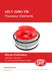
LELY JUNO 150
Feed Pusher
Operator Manual
5.4301.8501.0 - Lely Control
EN - English Original
INTENTIONALLY BLANK
ii
TRADEMARKS, COPYRIGHT AND
DISCLAIMER
5.4301.8501.0 - Lely Control
Lely, Astronaut, Astri, Atlantis, Attis, AWS, C4C, Calm, Caltive, Commodus,
Compedes, Cosmix, Discovery, F4C, Fertiliner, Gravitor, Grazeway,
Hibiscus, Hubble, Juno, L4C, Lely Center, Lelywash, Lotus, Luna, Nautilus,
Orbiter, Quaress, Qwes, SAE, Shuttle, Splendimo, Storm, T4C, Tigo, Vector,
Viseo, Voyager, Walkway and Welger are registered trademarks of the Lely
Group.
The right of exclusive use belongs to the companies of the Lely Group. All
rights reserved. The information given in this publication is provided for
information purposes only and does not constitute an offer for sale. Certain
products may not be available in individual countries and products supplied
may differ from those illustrated. No part of this publication may be copied or
published by means of printing, photocopying, microfilm or any other
process whatsoever without prior permission in writing by Lely Holding S.à
r.l. Although the contents of this publication have been compiled with the
greatest possible care, Lely cannot accept liability for any damage that might
arise from errors or omissions in this publication.
The English language manual is the original manual. Translations into other
languages use the English language manual as the source document. Lely
accepts no liability for discrepancies between the original English language
manual and versions in other languages. If there is a conflict over the
content and accuracy of any translated manual, the English language
manual is the authority document.
Copyright © 2014 Lely Industries N.V.
All rights reserved
Lely Industries N.V.
Cornelis van der Lelylaan 1
3147 PB Maassluis
the Netherlands
Phone: +31 (0)88 1228221
Fax: +31 (0)88 1228222
Website: www.lely.com
Trademarks, Copyright and Disclaimer
1
5.4301.8501.0 - Lely Control
INTENTIONALLY BLANK
2
Trademarks, Copyright and Disclaimer
WARRANTY RESTRICTIONS
Excluded from this warranty are any cost or expenses due to:
•
•
•
•
•
•
Abnormal use of the equipment which is not according to the
specifications stated in the Operator Manual or handled during the
Operators Service and Maintenance Certification program.
The result of any intervention by technicians other than Lely service
technicians or technicians who have Lely’s approval to perform certain
duties.
Incidents such as freezing, ice, fire, flood, inundation or any other form of
excessive water, lightning.
Defect of the electrical system or grounding.
Hacking activities, viruses or the like.
Damage to the electrical system as a result of vermin or the like.
Warranty does not apply to consequential damage which does not involve
the machine itself.
5.4301.8501.0 - Lely Control
All systems are tested. However in the event of a malfunction Lely cannot be
held responsible for consequential damage.
Warranty Restrictions
1
5.4301.8501.0 - Lely Control
INTENTIONALLY BLANK
2
Warranty Restrictions
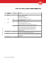
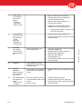
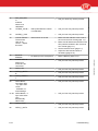
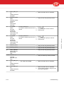
LIST OF INCLUDED AMENDMENTS
No:
Issue Date
(yy/mm)
Chapter(s)
Remarks
6
14/06
All
Bluetooth operation added
Pause button added
Operator manual separated
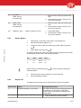
5
11/09
All
Product name changed to "JUNO 150"
4, 6
Feed groups added
4, 6
Push power for feed groups added
All
Full revision of the manual
- Software changes are incorporated
- Manual complies to the new documentation standard
5.4301.8501.0 - Lely Control
4
10/07
2, 4, 5, 6, 8, 9 Rewritten: safety devices, component description
Added: new pictures (new position inductive sensor)
Added: updated software description (Modify Route)
Added: new procedure 'Adjust the inductive sensor'
Updated: alarm list
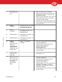
3
09/11
2, 4, 5, 7
Added: description, installation and maintenance procedures with
reference to the safety bar and the battery stop
2
09/03
2, 4, 8
Added: safety decals, installation safety decals, description feed
push power, procedure adjust the feed push power, description new
multiboard pcb
1
08/12
List of included Amendments
Initial issue
1
5.4301.8501.0 - Lely Control
INTENTIONALLY BLANK
2
List of included Amendments
PREFACE
Manual Contents
This manual contains the information necessary to operate the JUNO 150
Feed Pusher.
Study and understand this information thoroughly before you operate the
JUNO 150 Feed Pusher. Failure to do so could result in personal injury or
damage to equipment. Please consult your local Lely service provider if you
do not understand the information in this manual, or if you need additional
information.
All information in this manual has been compiled with care. Lely shall not be
liable for errors or faults in this manual. The recommendations are meant to
serve as guidelines. All instructions, pictures and specifications in this
manual are based on the latest information that was available at the time of
publication. Your JUNO 150 Feed Pusher may comprise improvements,
features or options that are not covered in this manual.
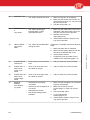
Applicability
5.4301.8501.0 - Lely Control
The table below shows the type numbers of JUNO 150 for which this manual
is applicable and the software version the procedures are based on.
Model designation
Model
Type number
Lely JUNO 150 Feed Pusher
5.4301.0020.1
Software version
The description, operation and procedures in this manual are based on the
software version:
•
•
•
ADS 3840 PCB: JUNSv01.07.XX
ADS 3641 PCB: 1.2.41 or higher
Lely Control app Android: 1.2.23 or higher.
Standard Torque Loading of Parts
All the nuts, bolts and screws used on the JUNO 150 Feed Pusher are
torque tightened to standard torque loadings applicable to the construction
materials used.
If a part has a non-standard torque loading, it is specified in the applicable
part of the manual.
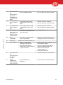
Registration
The Type and Serial Number Plate is attached to the front side of the JUNO
150 Feed Pusher. Always include the type and serial numbers of JUNO 150
when you contact your local Lely service provider or order spare parts.
Preface
1
Type and Serial Number Plate
We suggest you complete the table below with the type and serial numbers
of your JUNO 150. This makes sure you can easily find the information.
Type number
5.4301.0020.1
Serial number
Only technicians certified by Lely Industries are authorized to do
corrective maintenance on the JUNO 150.
If people who are not certified by Lely Industries do maintenance on
the JUNO 150, the warranty on the JUNO 150 becomes invalid.
Before a technician does maintenance on a JUNO 150, the owner must
examine the service pass of the technician and make sure the technician is
currently certified to do maintenance on the JUNO 150.
Technician Training
All the technicians certified by Lely Industries have completed an approved
training program, and passed written and practical examinations during and
at the end of the training program. The examinations are done under
supervision of a product specialist and include troubleshooting and
corrective maintenance of the JUNO 150.
There are five certification levels:
•
•
•
•
•
Installation Technician (certification valid for two years)
Service Engineer (certification valid for two years)
Senior Service Engineer (certification valid for two years)
Product Specialist (certification valid for one year)
Master Product Specialist (certification valid for one year).
During training, a trainee is permitted to work for up to a maximum of six
months on a JUNO 150 in the presence of a certified technician.
2
Preface
5.4301.8501.0 - Lely Control
Maintenance Authorization
When the training program is completed successfully, Lely issues a
certificate and a service pass to the technician. The service pass contains
the following information:
•
•
•
•
The name of the technician
A photograph of the technician
The certification number of the technician
The date of expiry of the certification.
Contact Number Local Service Provider
We suggest you write the telephone number and email address of your local
service provider contact in the table below. This makes sure you can easily
find the information.
Telephone number
5.4301.8501.0 - Lely Control
email address
Preface
3
4
5.4301.8501.0 - Lely Control
INTENTIONALLY BLANK
Preface
Table of Contents
1.
Introduction.........................................................................................................................................1-1
2.
Safety...................................................................................................................................................2-1
2.1
Introduction.............................................................................................................................. 2-1
2.2
Signal Icons..............................................................................................................................2-1
2.3
Safety Instructions....................................................................................................................2-1
2.4
5.4301.8501.0 - Lely Control
2.5
3.
Electrical Safety....................................................................................................................... 2-2
2.3.2
Operating Safety...................................................................................................................... 2-2
2.3.3
Maintenance Safety................................................................................................................. 2-4
Safety Decals........................................................................................................................... 2-4
2.4.1
Safety Decal Messages........................................................................................................... 2-4
2.4.2
Installation of Safety Decals.....................................................................................................2-7
2.4.3
Maintenance of Safety Decals................................................................................................. 2-8
Safety Devices......................................................................................................................... 2-8
2.5.1
Emergency Stop Button........................................................................................................... 2-8
2.5.2
Pause button............................................................................................................................2-8
2.5.3
Protection Ring........................................................................................................................ 2-9
2.5.4
Safety Bracket..........................................................................................................................2-9
2.5.5
Interlocking Lid.........................................................................................................................2-9
2.5.6
Acoustic Warning Device......................................................................................................... 2-9
2.5.7
Hardware Safety Protection................................................................................................... 2-10
2.5.8
Software Controlled Charging System...................................................................................2-10
2.5.9
Fuse....................................................................................................................................... 2-10
2.5.10
Overload Protection............................................................................................................... 2-10
2.5.11
Battery....................................................................................................................................2-10
2.5.12
Battery Stop........................................................................................................................... 2-10
Specifications..................................................................................................................................... 3-1
3.1
3.2
3.3
4.
2.3.1
Feed Pusher.............................................................................................................................3-1
3.1.1
Dimensions and Weight........................................................................................................... 3-1
3.1.2
Battery......................................................................................................................................3-1
3.1.3
Operation................................................................................................................................. 3-1
3.1.4
Miscellaneous.......................................................................................................................... 3-1
Charging Station...................................................................................................................... 3-2
3.2.1
Dimensions and Weight........................................................................................................... 3-2
3.2.2
Battery Charger........................................................................................................................3-2
Requirements Smartphone...................................................................................................... 3-2
Description and Operation................................................................................................................ 4-1
4.1
Introduction.............................................................................................................................. 4-1
4.2
Component Description............................................................................................................4-2
Table of Contents
v
4.3
4.4
Feed Pusher Vehicle................................................................................................................4-2
4.2.2
Charging Station...................................................................................................................... 4-8
User Interface...........................................................................................................................4-9
4.3.1
Work.......................................................................................................................................4-10
4.3.2
Routes....................................................................................................................................4-13
4.3.3
Settings.................................................................................................................................. 4-22
4.3.4
Alarms....................................................................................................................................4-23
4.3.5
Service................................................................................................................................... 4-24
Operation............................................................................................................................... 4-24
4.4.1
Routes, Actions, Manual Routes and Time Paths................................................................. 4-24
4.4.2
Control System...................................................................................................................... 4-25
Operating Instructions....................................................................................................................... 5-1
5.1
Install or Update the Lely Control app on Your Smart Phone.................................................. 5-1
5.2
Rename the JUNO 150 on the Smartphone............................................................................ 5-1
5.3
Set the farmer password.......................................................................................................... 5-1
5.4
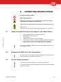
Open or Close the Lid.............................................................................................................. 5-2
5.5
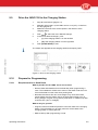
Switch ON or OFF the JUNO 150............................................................................................ 5-2
5.6
Operate Device Specific Software with a Smartphone............................................................ 5-3
5.7
Start the Software on Your Smartphone.................................................................................. 5-3
5.8
Manually Drive the JUNO 150..................................................................................................5-4
5.9
Drive the JUNO 150 to the Charging Station........................................................................... 5-5
5.10
Prepare for Programming.........................................................................................................5-5
5.10.1
5.11
Requirements for a Good Route.............................................................................................. 5-5
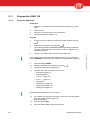
Program the JUNO 150............................................................................................................5-6
5.11.1
Program a New Route............................................................................................................. 5-6
5.11.2
Copy a Route......................................................................................................................... 5-10
5.11.3
Modify a Route.......................................................................................................................5-10
5.11.4
Reset a modified Route to the previous Version....................................................................5-10
5.11.5
Delete a Route....................................................................................................................... 5-11
5.11.6
Set or Delete a Manual Route................................................................................................5-11
5.11.7
Define Feed Groups...............................................................................................................5-12
5.11.8
Define the Push Power for a Feed Group..............................................................................5-12
5.11.9
Set a Time Path..................................................................................................................... 5-13
5.11.10
Make a Backup...................................................................................................................... 5-13
5.11.11
Copy a Backup file from the Smartphone to a PC................................................................. 5-14
5.11.12
Copy a Backup file from a PC to the Smartphone................................................................. 5-14
5.12
Start or Stop Timed Actions................................................................................................... 5-14
5.13
Start, Stop or Pause a Manual Route.................................................................................... 5-15
5.14
Block a Route.........................................................................................................................5-16
5.15
Reset the Emergency Stop Button.........................................................................................5-16
6.
Maintenance........................................................................................................................................6-1
vi
Table of Contents
5.4301.8501.0 - Lely Control
5.
4.2.1
6.1
Introduction.............................................................................................................................. 6-1
6.2
Preventive Maintenance Schedule...........................................................................................6-1
6.3
Preparation...............................................................................................................................6-1
6.4
7.
5.4301.8501.0 - Lely Control
Remove or Install the Cover.................................................................................................... 6-2
6.3.3
Switch OFF or ON the JUNO 150............................................................................................6-4
Maintenance Procedures......................................................................................................... 6-5
6.4.1
Clean the Charging Strips and the Charging Electrodes......................................................... 6-5
6.4.2
Adjust the Skirt Height............................................................................................................. 6-6
7.1
Introduction.............................................................................................................................. 7-1
7.2
Settings.................................................................................................................................... 7-1
7.2.1
Set the Real-Time Clock.......................................................................................................... 7-1
7.2.2
Set the Display Language........................................................................................................7-1
7.2.3
Modify the Beep Frequency for a Route.................................................................................. 7-2
7.2.4
Modify the Beep Length........................................................................................................... 7-2
7.2.5
Modify the Feed Push Power...................................................................................................7-2
Tests........................................................................................................................................ 7-3
7.3.1
Analyse the Reliability of a Route............................................................................................ 7-3
7.3.2
Test a Route............................................................................................................................ 7-3
7.3.3
Make sure the Battery is Loaded............................................................................................. 7-3
7.3.4
Make sure the Battery is Charging...........................................................................................7-4
7.3.5
Make sure the Bluetooth Connection is Reliable..................................................................... 7-4
7.3.6
Test the Ultrasonic Sensor.......................................................................................................7-5
Troubleshooting................................................................................................................................. 8-1
8.1
Introduction.............................................................................................................................. 8-1
8.2
Alarms and Reports................................................................................................................. 8-1
8.3
8.4
9.
Break or close the Power Circuit..............................................................................................6-1
6.3.2
Test and Adjustment.......................................................................................................................... 7-1
7.3
8.
6.3.1
8.2.1
Recover alarms........................................................................................................................8-1
8.2.2
Alarm List................................................................................................................................. 8-2
8.2.3
Read a Report........................................................................................................................8-13
8.2.4
Report List..............................................................................................................................8-13
8.2.5
Information Report List...........................................................................................................8-15
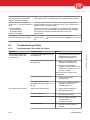
Troubleshooting Tables..........................................................................................................8-16
8.3.1
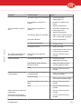
Troubleshooting Table JUNO 150 Vehicle.............................................................................8-16
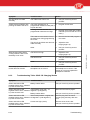
8.3.2
Troubleshooting Table JUNO 150 Charging Station..............................................................8-18
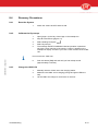
Recovery Procedures.............................................................................................................8-19
8.4.1
Reset the System...................................................................................................................8-19
8.4.2
Calibrate the Gyroscope........................................................................................................ 8-19
8.4.3
Charge the JUNO 150........................................................................................................... 8-19
Diagrams............................................................................................................................................. 9-1
Glossary of Terms
Table of Contents
vii
5.4301.8501.0 - Lely Control
Index
viii
Table of Contents
1.
INTRODUCTION
The JUNO 150 Feed Pusher is a battery-driven vehicle that pushes the
forage towards the feed fence of the barn. This gives the cows better access
to more fresh food through the day. The rotating lower part of the side of the
JUNO 150 pushes the forage against the feed fence while the vehicle drives
along the feeding alley.
The dairy farmer (operator) uses the Lely Control app on the smartphone to
program the route to be followed by the JUNO 150. Routes can be
programmed flexibly. The dairy farmer has the option to do more feed
pushing in some areas of the barn during certain hours of the day.
The information in this manual is for operators. The operator uses the
information to program and operate the JUNO 150. The operator also uses
the information to do maintenance.
The operator must read the operating instructions for daily operation and for
the setup of routes and time paths. He must read the test and adjustment
section for the setup and for testing the JUNO 150 and routes. He must also
read the maintenance and troubleshooting sections for preventive and basic
corrective maintenance instructions.
5.4301.8501.0 - Lely Control
The operator should refer to the description and the operation section for
background information. The operator must also read and understand the
safety instructions in section 'Safety'.
Introduction
1-1
5.4301.8501.0 - Lely Control
INTENTIONALLY BLANK
1-2
Introduction
2.
2.1
SAFETY
Introduction
The JUNO 150 Feed Pusher is an automated machine. Therefore it is of the
utmost importance to obey all safety instructions.
The safety alert symbol identifies important safety messages on your JUNO
150 Feed Pusher and in the manual. When you see this symbol, be alert to
the possibility of personal injury or death. Follow the instruction of the safety
message.
5.4301.8501.0 - Lely Control
Safety Alert Symbol
2.2
Signal Icons
Note the use of the signal words DANGER, WARNING and CAUTION with
the safety messages. The signal word for each message uses the following
guidelines:
Danger: indicates an imminently hazardous situation that,
if not avoided, will result in death or serious injury.
Warning: indicates a potentially hazardous situation that, if not
avoided, could result in death or serious injury, and includes hazards
that are exposed when guards are removed.
Caution: indicates a potentially hazardous situation that, if not avoided, may
result in minor or moderate injury or product or property damage.
Note: this shows extra information that may help the reader.
2.3
Safety Instructions
YOU are responsible for the SAFE operation and maintenance of your
JUNO 150 Feed Pusher. YOU must make sure that you and anyone else
who is going to operate, maintain or work in the vicinity of the JUNO 150
knows all the related SAFETY information in this manual.
YOU are the key to safety. Good safety practices protect you and the people
around you. Make these practices a working part of your safety program.
Make sure EVERYONE who operates, maintains or works near the feed
Safety
2-1
pusher obeys the safety precautions. Do not risk injury or death by ignoring
good safety practices.
•
•
•
•
•
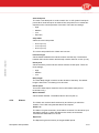
Electrical Safety
•
•
•
•
•
2.3.2
Only an authorized electrician must install the electrical power supply for
the charging station of the JUNO 150.
Make sure the electrical grounding of the electrical system and all parts of
the charging station of the JUNO 150 meet the local rules and
regulations.
Replace any damaged electrical lines, conduits, switches and
components immediately .
Switch the power OFF with the OFF button on the ADS 3840 PCB before
you start to work on the system.
Pull the plug from the socket before you start to work on the charging
station.
Operating Safety
Remote operation of the smartphone or tablet by remote desktop
software (such as, but not limited by, Teamviewer) is strictly forbidden
to avoid dangerous situations.
The maximum amount of energy the electric pulse of the collision detector
transfers is 15 mJ (at 500R). This does not harm cows or humans.
•
•
•
•
•
•
2-2
Read and understand this manual and all safety signs before you connect
power supplies to operate, maintain or adjust the JUNO 150
Only trained persons are permitted to operate the JUNO 150
Make sure all covers are installed before you operate the JUNO 150
Make sure the safety bracket is installed on the front side before you
operate the JUNO 150
Only operate the JUNO 150 in a closed and marked feed alley
The JUNO 150 shall be operated under supervision only or in areas that
are not accessible for unauthorized people, especially small children
Safety
5.4301.8501.0 - Lely Control
2.3.1
JUNO 150 owners must train operators before they operate the JUNO
150. This training must be repeated at least annually
The operator must read, understand and obey all safety and operating
instructions in the manual
A person who has not read and understood all safety and operating
instructions is not permitted to operate the JUNO 150
Do not modify the equipment in any way. Unauthorized modification may
impair the function and/or safety and could affect the life of the
equipment, and persons
Only use approved spare parts, and make sure they are only installed by
authorized technicians.
•
•
•
•
5.4301.8501.0 - Lely Control
•
Keep hands, feet, hair and clothing away from all moving parts
Never touch the collision detector when the JUNO 150 is moving to avoid
an electric shock
Contact your nearest Lely service provider if you have any questions
Review safety related items with all operators frequently (annually)
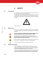
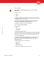
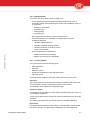
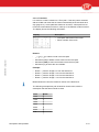
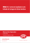
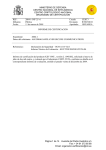
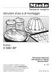
Make sure the slope of the floor is no more than 3 degrees (4 cm per 100
cm).
Figure 1. Maximum slope
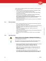
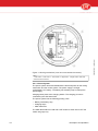
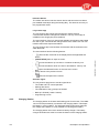
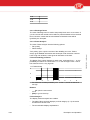
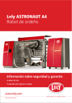
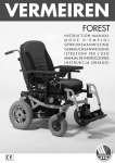
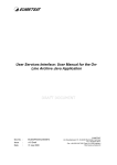
The maximum amount of energy the electric pulse of the collision detector
transfers is 15 mJ (at 500R). This does not harm cows or humans.
Cows are deterred from touching the vehicle by an electric pulse which is
activated when driving the route. The pulse is on the collision detector (see
figure on page 2‑4) (1) that surrounds the vehicle.
Safety
2-3
Figure 2. Areas with Electric Pulse
2.3.3
Maintenance Safety
•
•
•
•
•
•
Read and understand the applicable manual and all safety signs before
you connect power supplies to operate, maintain or adjust the JUNO 150
Only trained persons are permitted to do corrective maintenance on the
JUNO 150
Keep tools and metal parts away from the battery
Disconnect and isolate the electrical power supply before you do work on
the JUNO 150
Do NOT spout water on the body of the JUNO 150. Use a wet brush to
clean the JUNO 150
Make sure all covers are installed when maintenance work is complete.
2.4
Safety Decals
2.4.1
Safety Decal Messages
General safety messages appear in this safety messages section. Specific
safety messages are in applicable parts of this manual when potential
hazards may occur if the instructions or procedures are not followed.
2-4
Safety
5.4301.8501.0 - Lely Control
KEY:
1. Collision detector
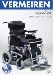
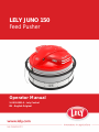
2.4.1.1 Rotating Parts - Entanglement Hazard
Figure 3. Rotating Parts - Entanglement Hazard Symbol
Danger of being entangled by rotating parts.
Keep hands, loose clothing, and long hair away from moving parts
during operation of the JUNO 150.
5.4301.8501.0 - Lely Control
2.4.1.2 High Voltage - Electric Shock Caution
Figure 4. Electric Shock - High Voltage Symbol
Electric shock.
Keep away from the collision detector during operation of the JUNO 150.
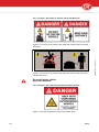
2.4.1.3 No Admittance for Unauthorized Persons
Figure 5. No admittance for unauthorized persons
Only persons who have read and understood all applicable safety
instructions are allowed to enter the area.
Safety
2-5
2.4.1.4 Danger - Do not Sit on Vehicle / Keep Safe Distance
Figure 7. 'Do not sit on the vehicle' and 'Keep safe distance' decal (except
Canada and USA)
Do not sit on the vehicle.
Keep safe distance.
2.4.1.5 Danger - Area with Unmanned Autonomous Vehicle
Figure 8. Area with unmanned autonomous vehicle decal
2-6
Safety
5.4301.8501.0 - Lely Control
Figure 6. 'Do not sit on the vehicle' and 'Keep safe distance' decal (Canada
and USA)
5.4301.8501.0 - Lely Control
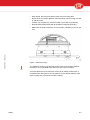
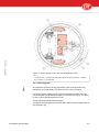
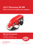
The safety decal 'Area with unmanned autonomous vehicle' must be
installed on a highly visible place near the entrance of the barn.
Figure 9. Position of the safety decals
KEY:
1. Electric Shock - High Voltage Symbol - 2. 'Do not sit on the vehicle' and 'Keep safe
distance' decal - 3. Rotating Parts - Entanglement Hazard Symbol
2.4.2
Installation of Safety Decals
1.
2.
3.
4.
5.
6.
7.
Safety
Make sure the installation surface is clean and dry.
Make sure the temperature of the mounting surface is not less than 5
°C (41 °F).
Identify the correct position for the decal before you remove the
backing paper.
Remove a small part of the backing paper.
Put the decal in the correct position on the mounting surface and
carefully press the small part of exposed adhesive surface of the
decal onto the mounting surface.
Slowly remove the backing paper and attach the rest of the decal to
the mounting surface.
Puncture small air pockets in the decal with a pin and use the backing
paper to smooth the decal.
2-7
2.4.3
Maintenance of Safety Decals
Safety decals on the JUNO 150 Feed Pusher display important and useful
information that will help you safely operate and maintain the JUNO 150.
Obey the instructions below to make sure all the decals stay in the correct
position and condition.
•
•
•
Keep the safety decals clean and legible at all times. Clean the safety
decals with soap and water. Do not use mineral spirits, abrasive cleaners
or other similar agents that may damage the safety decals
Replace safety decals that are missing or are illegible
Safety decals can be purchased from your local Lely service provider.
2.5
Safety Devices
2.5.1
Emergency Stop Button
An emergency stop button (see figure on page 2‑11) is installed on the top
of the JUNO 150. The emergency stop button is accessible with the cover of
the JUNO 150 closed (see figure on page 4‑1).
To reset the emergency stop button, turn the button clockwise and pull it out
until it unlocks.
2.5.2
Pause button
A pause button is installed on the JUNO 150. When the pause button is
pushed while the JUNO 150 is in operation, the JUNO 150 goes into pause
mode:
•
•
•
•
The JUNO 150 stops.
The LED light in the pause button turns on.
The operational sound of the JUNO 150 is turned off.
The user interface on the smartphone displays a question to resume or
cancel the route.
When the pause button or the button in the Lely Control app is pushed
shortly while the JUNO 150 is in pause mode, the JUNO 150 goes back into
work mode:
•
The JUNO 150 goes back into operation.
•
•
The LED light in the pause button turns off.
The operational sound of the JUNO 150 is turned on.
The pause button can be operated remotely with the Lely Control app on the
smartphone.
If an alarm occurs, the LED in the pause button blinks. The alarm must be
confirmed with the Lely Control app on the smartphone.
2-8
Safety
5.4301.8501.0 - Lely Control
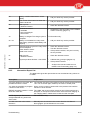
When the button is pressed, the JUNO 150 immediately stops operation.
Status of the JUNO 150
LED status of the pause button
Start up
Blink
Out of operation. Lely Control app in main tab
menu Work
On
Out of operation. Lely Control app in other menu
Blink
JUNO 150 paused
On
JUNO 150 in normal operation
Off
Alarm
Blink
2.5.3
Protection Ring
The maximum amount of energy the electric pulse of the protection ring
transfers is 15 mJ (at 500R). This does not harm cows or humans.
The JUNO 150 has a rubber protection ring (see figure on page 2‑11) that
stops the vehicle immediately when the vehicle hits an object that is at least
60 cm above floor level. The reaction of the JUNO 150 depends on the
object type.
5.4301.8501.0 - Lely Control
•
•
If the vehicle hits a solid object (for instance a tractor), the JUNO 150
drives back until there is no contact with the obstacle. After 2 seconds the
vehicle tries to continue its route. If it hits the object again, it drives back
again (until there is no contact), stops and generates an alarm message.
If the vehicle hits an object that is not solid, or if a cow bites the ring, the
vehicle waits 2 seconds and tries to continue its route. If the collision
detector is activated 4 more times (within 50 cm), the vehicle stops and
generates an alarm message.
The protection ring has a pulse on it while the JUNO 150 is driving a route.
2.5.4
Safety Bracket
The safety bracket (see figure on page 2‑11) on the front actuates the
protection ring when it hits an object that is less than 60 cm above floor
level. The JUNO 150 immediately stops.
2.5.5
Interlocking Lid
The JUNO 150 has an interlocking lid that shuts off the power whenever it is
opened. The JUNO 150 stops immediately when the lid is opened. The
detector is integrated in the emergency stop button device.
2.5.6
Acoustic Warning Device
An acoustic warning device alerts persons and cows when the vehicle starts
to move, moves or when an alarm occurs.
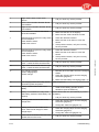
The beep lengths and beep frequencies of the acoustic warning device are:
Operational state of the JUNO 150
Beep frequency acoustic warning device
Normal operation
Once per 2 seconds (default)
An alarm occurred
3 short beeps every minute
The acoustic warning device (page 2‑11) is installed on the JUNO 150.
Safety
2-9
2.5.7
Hardware Safety Protection
All safety devices are controlled by software and hardware. If the software
fails, the hardware takes over.
2.5.8
Software Controlled Charging System
The operational software of the JUNO 150 controls the charge system. This
allows to keep the vehicle connected to the charging station when it is not
moving, even if the battery is fully charged. The software prevents
overcharging the battery and keeps it fully charged until the next operation.
2.5.9
Fuse
The ADS 3840 PCB has a one-time-use fuse that breaks the circuit in the
event of a power malfunction or an electrical short-circuit.
2.5.10
Overload Protection
2.5.11
Battery
The battery is filled with gel and is completely sealed to protect it against
leakage.
2.5.12
Battery Stop
The battery stop is used to disconnect the battery. It is installed on the
battery.
2-10
Safety
5.4301.8501.0 - Lely Control
The drive motors are protected against overload. If the current is high for a
long time the overload protection operates and stops the JUNO 150 to
prevent overheating. An alarm message is also generated.
5.4301.8501.0 - Lely Control
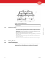
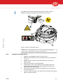
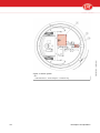
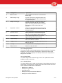
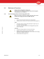
Figure 10. Position of the safety devices
KEY:
1. Protection ring - 2. Safety bracket - 3. Pause button - 4. Emergency stop button - 5.
Acoustic warning device - 6. Interlocking switch lid
Safety
2-11
5.4301.8501.0 - Lely Control
INTENTIONALLY BLANK
2-12
Safety
3.
3.1
Feed Pusher
3.1.1
Dimensions and Weight
3.1.3
3.1.4
•
•
•
•
•
•
Diameter: 156 cm (61.4 in)
Height: 106 cm (41.7 in)
Weight: 575 kg (1268 lbs)
Rotating part height: 60 cm (23.6 in)
Maximum width of feed: 200 cm (78.7 in)
Maximum height of feed: 75 cm (29.5 in).
•
•
•
•
•
Number of batteries: 1
Weight: 19.9 kg (43.9 lbs)
Nominal voltage: 12 V
Capacity: 55 Ah
Charging time: 6 hours maximum
•
•
•
•
•
Spare capacity: 120 min
Length: 254 mm (10.0 in)
Width: 174 mm (6.9 in)
Height, including battery terminals: 195 mm (7.7 in)
Height, excluding battery terminals: 173 mm (6.8 in)
•
•
•
•
•
•
•
Number of different programmable routes: max. 16
Number of actions per route: max. 125
Number of routes per time path: max. 48
Maximum duration of a time path: 24 hour
Travel speed: 12 m/min (display: 200)
Maximum driving time without charging: 2 hours
Route programming: with the Lely Control app on smartphone.
•
•
•
•
•
•
•
Drive: 2× electric motor
Number of wheels: 3
Average power consumption: 0.05 kWh
Determination of direction of motion: using gyroscope
Determination of distance to feed fence: using ultrasonic sensor
Determination of distance travelled: via encoders on motors
Calibration points: Metal stripes along feed alley.
Battery
5.4301.8501.0 - Lely Control
3.1.2
SPECIFICATIONS
Operation
Miscellaneous
Specifications
3-1
3.2
Charging Station
3.2.1
Dimensions and Weight
Charging station
•
•
•
•
•
Width: 37 cm (14.6 in)
Depth: 25 cm (9.8 in)
Height: 62.5 cm (24.6 in)
Weight excluding floor column: 40 kg (88.2 lbs)
Weight including floor column: 84 kg (185.2 lbs).
Floor column
3.3
Width: 37 cm (14.6 in)
Depth: 10 cm (3.9 in)
Height: 210 cm (82.7 in)
Weight floor column: 44 kg (97 lbs).
•
•
•
•
•
•
•
•
•
Type: Exendis (9-1188-0027-0)
Input voltage: 180 - 240 VAC / 50 Hz or 115 / 60 Hz
Output voltage: 17 VDC
Max. charge current: 20 A
Safety features: reversed connections, short circuit
Weight: 2 kg (4.4 lbs)
Length, excluding battery terminals: 200 mm (7.9 in.)
Width: 150 mm (5.9 in.)
Height: 70 mm (2.8 in.).
Battery Charger
5.4301.8501.0 - Lely Control
3.2.2
•
•
•
•
Requirements Smartphone
Use of a tablet is technically possible if it meets the specifications. However,
the user interface might not be displayed optimally since it is designed for
smartphones.
•
•
•
•
•
•
•
3-2
Screen resolution 480 x 800 (or higher).
Android 2.3.x, 4.0.x or 4.2.x.
Bluetooth version 2.0, 2.1, 3.0, 4.0 dual mode (4.0 single mode is not
supported) .
Compliance with 1999/5/EC european directive for Radio and
Telecommunications Terminal Equipment.
For software updates a WiFi or 3G network must be available.
Processor: 1 GHz (or higher).
Android smartphone must have at least 10 MB free storage.
Specifications
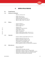
4.
4.1
DESCRIPTION AND
OPERATION
Introduction
5.4301.8501.0 - Lely Control
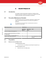
This chapter describes the parts of the JUNO 150 Feed Pusher. It also
explains how the parts work together to push the feed to the feed fence.
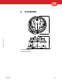
Figure 11. Main components
KEY:
1. Charging station - 2. Metal guiding strip (90 mm) - 3. Juno vehicle
Description and Operation
4-1
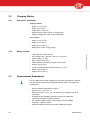
4.2
Component Description
4.2.1
Feed Pusher Vehicle
The feed pusher vehicle has the following main components:
•
•
•
•
•
•
5.4301.8501.0 - Lely Control
•
Cover
Skirt
Concrete block
Driving mechanism
Power system, to store and distribute power
Control system, to control the JUNO 150 using the programmed route
and sensors
Shock system.
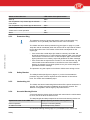
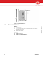
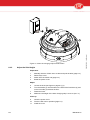
Figure 12. Main components JUNO 150 Feed Pusher
KEY:
1. Hinged lid - 2. Cover - 3. Charging strips - 4. Interlocking protection ring - 5. Interlocking
guard - 6. Skirt - 7. Concrete block - 8. Pause button - 9. Emergency stop button - 10.
Acoustic warning device - 11. Bluetooth antenna - 12. Hoisting eye - 13. ADS 3840 PCBbox with ON/OFF buttons
4-2
Description and Operation
4.2.1.1 Covering
Do not operate the JUNO 150 without the cover to ensure proper
functioning.
The JUNO 150 has:
•
•
•
Cover
Hinged lid
Skirt.
The cover is installed on the frame with two elastic fasteners, the hinged lid
is installed on the cover. The cover has a cover switch which stops operation
immediately when the cover is removed.
The skirt is the rotating surface on the lower section of the vehicle. This
device rotates and pushes the forage against the feed fence while the
vehicle drives in a straight line along the feeding alley.
The technician removes the cover to do maintenance.
4.2.1.2 Carriage and Contra Weight
5.4301.8501.0 - Lely Control
The carriage has:
•
•
•
Frame
Wheel support
Front wheel.
The front wheel is a support wheel.
The frame is attached to a concrete contra weight. The contra weight weighs
335 kg (739 ft.) which makes sure the JUNO 150 has sufficient mass to push
the forage. On top of the concrete contra weight a hoisting eye is installed.
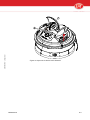
4.2.1.3 Driving Mechanism
The drive motors, that are attached to plates on the contra weight, drive the
two wheels on the side via chains and gear sets. The vehicle has no
steering-wheel. Its direction is controlled by letting one of the motors run
faster than the other.
The driving mechanism has the following parts:
•
•
•
•
Drive motor (2×)
Chain (2×)
Gear set (2×)
Wheel (left and right).
The drive motors get input from the ADS 3840 PCB.
Description and Operation
4-3
KEY:
1. Left wheel - 2. Left motor - 3. Front wheel - 4. Right motor - 5. Right wheel - Gear sets
and chains are not shown.
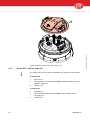
4.2.1.4 Power System
The power system stores and distributes the electrical power for the driving
mechanism and the control system. The power supply is a single
rechargeable 12 V battery. The battery has a battery stop to interrupt the
power supply.
Charging takes place at the charging station. The charging process is
controlled by the ADS 3840 PCB.
The power system has the following primary parts:
•
•
•
Battery with battery stop
Charging strips
ADS 3840 PCB.
The ADS 3840 PCB has a ON and a OFF button to switch ON or OFF the
JUNO 150 (page 6‑4).
4-4
Description and Operation
5.4301.8501.0 - Lely Control
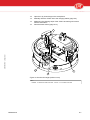
Figure 13. Driving mechanism (cover and concrete block removed)
5.4301.8501.0 - Lely Control
Figure 14. Power system (cover and contra weight removed)
KEY:
1. Charging strip - 2. PCB-box with ADS 3840 PCB and ON and OFF buttons - 3. Battery
stop - 4. Battery - 5. Charging strip
4.2.1.5 Shock System
The maximum amount of energy the electric pulse of the protection ring
transfers is 15 mJ (at 500R). This does not harm cows or humans.
The shock system makes sure the cows do not block the JUNO 150. The
power energizer (2) generates the pulse in the protection ring (3). The pulse
is only on when the vehicle drives a route.
The shock system has a power energizer.
The power energizer gets input from the ADS 3840 PCB and sends output to
the protection ring.
Description and Operation
4-5
5.4301.8501.0 - Lely Control
Figure 15. Shock system
KEY:
1. ADS 3840 PCB - 2. Power energizer - 3. Protection ring
4-6
Description and Operation
4.2.1.6 Safety System
The JUNO 150 has a safety system to (page 2‑8):
•
Protect people and animals against mechanical hazards by a set of
interlocking safety devices that stop the JUNO 150 immediately when hit
or openened:
•
•
•
•
•
•
Warn people and animals by acoustic warning device
Ensure that a fault in the hardware or software does not lead to
hazardous situations:
•
•
•
•
•
Hardware safety protection
Software controlled charging system
Overload protection of the drive motors
Fused control system.
Protect people during maintenance:
•
•
5.4301.8501.0 - Lely Control
Emergency stop button
Protection ring
Safety bracket
Interlocking lid.
Sealed maintenance-free battery
Battery stop to disconnect the battery.
4.2.1.7 Control System
The control system has the following parts:
•
•
•
•
•
ADS 3840 PCB
Encoders
Ultrasonic sensor
Gyroscope (embedded on the ADS 3840 PCB)
Inductive sensor.
All the parts work together to keep the JUNO 150 on the correct route.
Encoders
Each drive motor has an encoder that counts the rotation of the motor shaft.
This information is used to calculate the position of the vehicle.
The encoders send outputs to the ADS 3840 PCB.
Ultrasonic Sensor
The ultrasonic sensor makes sure the JUNO 150 follows the wall or fence at
a pre-determined distance.
A foam ring is attached to the sensor to minimize reflections and to focus the
ray beam.
The sensor gets inputs from and sends outputs to the ADS 3840 PCB.
Gyroscope
The gyroscope measures the turning angle. This information is used to find
the correct direction. The gyroscope is installed on the ADS 3840 PCB.
Description and Operation
4-7
Inductive Sensor
The JUNO 150 has an inductive sensor device with two sensors to detect
pre-installed metal strips along the feeding alley. This ensures accuracy of
the programmed routes.
Lely Control app
The Lely Control app controls and monitors the JUNO 150 and
communicates with the management software. The Lely Control app is
available in the Google play store (Android).
The user interface of the Lely Control app displays nine buttons that enable
the user to give commands and change values in the JUNO 150. The user
interface also shows reports and alarms.
The Lely Control app communicates via bluetooth with the software on the
ADS 3840 PCB.
•
[
] Execute the command on the display above the applicable soft
button.
[START/STOP] starts or stops an action.
•
[
] moves the selector up one item or increases a value by one.
•
[
] moves the selector down one item or decreases a value by one.
•
•
•
•
opens the selected function or the next menu screen.
[ESC] returns to the previous screen.
reduces the speed of the vehicle.
Acoustic signal
The Lely Control app gives an acoustic signal when:
•
•
•
•
•
4.2.2
The JUNO 150 is in normal operation
Settings are saved
The calibration of the gyroscope is finished
Backup is finished (create / restore)
Programming a route
Charging Station
The charging station is the start and finishing point for all routes. The JUNO
150 can be left permanently connected to the charging station. This keeps
the battery in good condition. The ADS 3840 PCB continuously examines
the voltage of the battery. It is not possible to overcharge the battery.
The charging station has a 20 A electronic battery charger. The battery
charger electrodes are at the front near the bottom of the charging station.
4-8
Description and Operation
5.4301.8501.0 - Lely Control
The user interface has the following buttons:
The charging station can be installed in the barn in two ways:
•
•
wall-mounted
floor-mounted.
If it is not possible to install the charging station to the wall, an optional floor
column can be supplied.
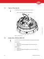
Battery Charger
The 20 A electronic battery charger has two indicator LEDs on the upper
right side. The meaning of the LEDs are:
4.3
Status
Charging LED
(orange)
Power LED (green)
Mains connected
OFF
ON
Charging (>1A)
ON
ON
Error
blinking
blinking
User Interface
5.4301.8501.0 - Lely Control
The JUNO 150 is operated with a smartphone with an Android operating
system. The smartphone communicates with the software via bluetooth. The
main menu on the smart phone has the following items:
•
•
•
•
•
•
Work
Routes
Test
Settings
Alarms
Service.
Figure 16. The Lely Control app menu structure
Description and Operation
4-9
Buttons:
4.3.1
•
[
] or [
] to select a menu item
•
•
[
] to confirm an action
[ESC] to go to the previous menu.
Work
The menu 'Work' is used for daily operation of the JUNO 150. You can
operate the JUNO 150 in automatic mode using a time path and in manual
mode.
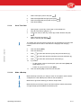
The menu 'Work' has the following submenu's:
ON /OFF (to switch the time path ON or OFF )
MANUAL ROUTE (to manually start a selected route)
MANUAL DRIVING (to manually drive the JUNO 150)
MANUAL CHARGER (to drive the JUNO 150 to the charging station,
following the strip).
] must be used to open next menu, [ESC] to open the
The button [
previous menu. A black dot on the right side of the screen indicates the
level. The highest level (ON/OFF ) has for example a dot on the upper side,
the lowest level (MANUAL CHARGER) a dot on the lower side.
Figure 17. Menu Work
The level is indicated by a tab with a black dot on the right side of a display.
There are four levels:
•
•
•
•
4-10
Menu 'Work', indicated by the upper dot
'Manual route', indicated by the second dot
'MANUAL DRIVING', indicated by the third dot
'MANUAL CHARGER', indicated by the fourth dot.
Description and Operation
5.4301.8501.0 - Lely Control
•
•
•
•
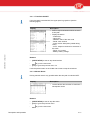
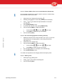
4.3.1.1 Time Path ON/OFF
If the time path is switched ON, the upper pane is grayed out (see the
following figure).
Display
Description
•
5.4301.8501.0 - Lely Control
•
Start or stop timed actions which are set in
a time path
Display the status:
- Actual time
- ON or OFF
- NextRun: start of the next route
- Route: route number
- Action: action description (visible during
route)
- Act.nr: sequence number for the action in
this route
- Runnr: run number
- Battery: battery voltage.
Buttons:
•
[START/STOP] to start or stop timed actions
•
[
•
[ESC] to go to the previous menu. Or
] to go to the next menu
Push the pause button on the JUNO 150 to start or stop timed actions.
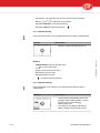
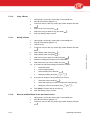
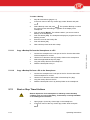
4.3.1.2 Manual Route
Driving manual route is only possible when the time path is switched OFF.
Display
Description
•
Let the vehicle drive a series of maximum 3
subsequent routes
Buttons:
Description and Operation
•
•
[START/STOP] to start or stop the action
[ESC] to go to the previous menu
•
[
] to go to the next menu
4-11
•
Soft button [>] to select the first, second or third route in the series
•
Button [
•
Soft button [Reset] to clear the set route(s)
•
Soft button [Save] to save the set route. [
] or [
] to select the route number
]
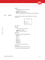
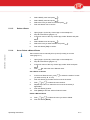
4.3.1.3 Manual Driving
Driving a manual route is only possible when the time path is switched OFF.
Display
Description
•
Move the vehicle manually (page 5‑4)
•
[START/STOP] to start or stop the action
•
[
•
•
•
[ESC] to go to the previous menu
Soft button [L] to turn right
Soft button [R] to turn left
•
[
5.4301.8501.0 - Lely Control
Buttons:
] to go to the next menu
] to select the drive direction
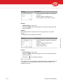
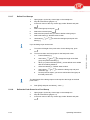
4.3.1.4 Manual Charger
Driving manually to the charger is only possible when the time path is
switched OFF.
Display
Description
•
•
4-12
Let the vehicle automatically drive to the
charging station (starting within 1 m from
the strip in front of the charging
station) (page 5‑5)
The values on the display indicate the
battery voltage and the charge current.
Description and Operation
Buttons:
4.3.2
•
[START/STOP] to start or stop the action
•
•
•
[
] to go to the next menu
[ESC] to go to the previous menu
Soft buttons [L] and [R] to select the position of the charging station
Routes
The menu 'Routes' is used for programming routes or for test and
adjustments.
Menu Routes
5.4301.8501.0 - Lely Control
Buttons:
•
[
] or [
] to select a menu item
•
•
[
] to confirm an action
[ESC] to go to the previous menu
New Route
A new route is built from the following actions:
•
•
•
•
•
•
•
•
Strip follow
Straight
Turn R -->
Turn L <-Feed push L
Ultrasound L
Charger strip
Waiting time.
A route has a maximum of 125 actions.
Strip follow
Follow the guiding strip on the floor (page 4‑1).
The display shows the following information:
Description and Operation
4-13
Display
Description
•
•
•
Actionr: sequence number for the action in
this route
RunDst: distance travelled in mm
Strip: indicates 1 when above the strip
Buttons:
•
•
[START/STOP] to start or stop
Soft button [MAN] to adjust the position of the vehicle to get a good start
position (direction).
Straight
Drive straight forward, only with the use of the gyroscope to correct the
position.
Display
Description
•
•
•
•
Actionr: sequence number for the action in
this route
RunDst: distance travelled in mm
Runnr: run number
Speed: speed in mm/s
Buttons:
•
•
[START/STOP] to start or stop
Soft button [MAN] to adjust the position of the vehicle to get a good start
position (direction)
•
Soft button [
] to change the direction.
Turn --> or <-- Turn
Turn right or left. You can choose from 9 standard turns to both right and left.
The chosen turn can be adjusted according to the specific situation. The
standard curves are:
4-14
Description and Operation
5.4301.8501.0 - Lely Control
The display shows the following information:
5.4301.8501.0 - Lely Control
•
•
•
Turn right 90 degrees, smoothly
Turn right 90 degrees
Turn right 180 degrees, stop in adjacent lane 100
cm (39.4 in) to the right.
•
•
•
Turn right 5 degrees
Turn right 25 degrees
Turn right 180 degrees, stop in adjacent lane 60
cm (23.6 in) to the right.
•
•
•
Turn right 60 degrees
Turn right 180 degrees
Turn right 180 degrees, stop in the adjacent lane
30 cm (11.8 in) to the right.
•
•
•
Turn left 90 degrees, smoothly
Turn left 90 degrees
Turn left 180 degrees, stop in adjacent lane 100
cm (39.4 in) to the left.
•
•
•
Turn left 5 degrees
Turn left 25 degrees
Turn left 180 degrees, stop in adjacent lane 60
cm (23.6 in) to the left.
•
•
•
Turn left 60 degrees
Turn 180 degrees
Turn left 180 degrees, stop in adjacent lane 30
cm (11.8 in) to the left.
After selecting an option, the variables of the turn can be adjusted. The
display shows the following information:
Description and Operation
4-15
Display
Description
•
•
•
•
Actionr: sequence number for the action in
this route
Angle of the turn, positive value (+) = turn
right, negative value (-) = turn left
The radius of the turn the vehicle will make:
0 = on the spot,
300 = turn around one of the drive wheels
The distance (in mm.) the vehicle first goes
back before making the turn (needed if the
vehicle is near an obstacle).
Buttons:
•
Soft button [<] to select the variable you want to modify
•
Push [
•
•
[START/STOP] to start or stop
Soft button [MAN] to adjust the position of the vehicle.
] to adjust the value of the selected variable
The same description applies for turning to the left.
Feed push L
Tracking along a feed fence on the left at a certain distance. The ultrasonic
sensor is used to measure the distance to the feed fence.
This function is like Ultrasound L, but the motor power is higher to assure
that the vehicle has enough power to push the forage to the feed fence.
The display shows the following information:
Display
Description
•
•
•
•
4-16
Actionr: sequence number for the action in
this route
RunDst: distance travelled in mm
UltraDst: actual distance to the wall or fence
(mm)
ULTRADST: adjustable distance to the wall
or fence (mm).
Description and Operation
5.4301.8501.0 - Lely Control
] or [
Buttons:
•
•
•
[
] or [
] to modify the value of the selected variable
[START/STOP] to start or stop
Soft button [MAN] to adjust the position of the vehicle.
Ultrasound L
Tracking along a wall or fence on the left at a certain distance. The
ultrasonic sensor is used to measure the distance to the wall or fence.
The display shows the following information:
Display
Description
•
•
•
5.4301.8501.0 - Lely Control
•
Actionr: sequence number for the action in
this route
RunDst: distance travelled in mm
UltraDst: actual distance to the wall or fence
(mm)
ULTRADST: adjustable distance to the wall
or fence (mm).
Buttons:
•
[
] or [
] to modify the value of the selected variable
•
•
[START/STOP] to start or stop
Soft button [MAN] to adjust the position of the vehicle.
Charger strip
Drive the vehicle back to the charging station. The JUNO 150 follows the
metal strip on the floor and finds the charging station independently (default
= on the left) (page 4‑1). The vehicles nose must be placed within 1 m (39.4
in) before the strip into the direction of the charging station.
The display shows the following information:
Display
Description
•
•
•
Description and Operation
Actionr: sequence number for the action in
this route
RunDst: distance travelled in mm
Strip: indicates 1 when above the strip.
4-17
Buttons:
•
•
•
Soft button [L] to modify the position of the charging station
Soft button [MAN] to adjust the position of the vehicle
[START/STOP] to start or stop.
Waiting time
Wait an adjustable time before continuing with the next action in a
route (page 5‑9). This action can be used in route that moves the vehicle
out of the feeding alley, keeps the vehicle waiting, and returns the vehicle to
the charging station when the work is done (for example bringing new forage
into the feeding alley).
The display shows the following information:
Description
•
•
Actionr: sequence number for the action in
this route
time : (min) Waiting time.
Buttons:
•
[
] or [
] to modify the value of the selected variable
•
•
[START/STOP] to start or stop
Soft button [Save] to save the setting.
4.3.2.1 Delete Route
The menu 'Delete route' is used to delete an existing route.
The display shows the following information:
Display
Description
•
List of set routes.
Buttons:
4-18
•
[
] or [
] to select a route
•
[
] to confirm.
Description and Operation
5.4301.8501.0 - Lely Control
Display
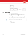
4.3.2.2 Time Path
It is useful to combine routes into a 'Time path'. If the time path is switched
ON the JUNO 150 drives the set routes automatically at the set times each
day (page 5‑13). A time path lasts maximum 24 hours. A time path has 48
time/route combinations maximum, made up of 16 different routes maximum.
The display shows the following information:
Display
Description
•
•
Time path: start times of set routes
Route: number of the route.
5.4301.8501.0 - Lely Control
Buttons:
•
[
] or [
] to select a route in the time path
•
•
•
Soft button [Del] to delete a timed route from the time path
Soft button [New] to add a new timed route to the time path
Soft button [>] to select the next variable.
Example:
•
•
•
•
Route 1 - push the forage 2 m from the feed fence
Route 2 - push the forage 1.8 m from the feed fence
Route 3 - push the forage 1.6 m from the feed fence
Route 4 - push the forage 1.4 m from the feed fence.
Measurements are from the ultrasonic sensor to the feed fence.
The following example time path is based on these routes, with the
assumption that the farmer feeds at 10:00:
Description and Operation
Time
Route
12:00
1
14:00
1
16:00
1
18:00
2
20:00
2
22:00
2
0:00
3
4-19
2:00
3
4:00
4
6:00
4
4.3.2.3 Blockage Route
The menu 'Blockage route' is used to temporally block one or more routes. If
you do not want the vehicle to drive within a particular distance from the feed
fence, block the routes that have that distance. Blocked routes will be
ignored by the time path.
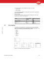
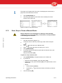
4.3.2.4 Route Analysis
The menu 'Route analysis' has the following options:
Fail. problty
Failure analys.
'Fail. problty' gives a quick overview of the reliability per route. 'Failure
analys' gives detailed information and shows per route the action numbers
have a high risk of failure. It also gives an indication of the fault.
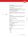
Failure Probability per Route
The display 'Fail. problty' displays for each route, numbered from 1 - 16, the
probability of a failure on a scale from 0 - 5. In the next figure route 1 has a
low risk and route 4 a very high risk.
1-2 Failures/route
5
3
1
1
•
2
3
4
5
6
7
8
If a routes has a failure probability of more than 2, the risk of failures is
too high.
Buttons:
•
•
[
] to open the next screen
[ESC] to go one level up.
Failure Analysis
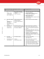
The display 'Failure analysis' has 2 tables:
•
•
4-20
The table Failure analysis displays per fault category (A - H) the action
numbers that causes a risk
The second table displays explanations.
Description and Operation
5.4301.8501.0 - Lely Control
•
•
5.4301.8501.0 - Lely Control
Display text
Explanation
A
Bend in action
Very unreliable route due to a combination of
factors (B-J)
B
Start-Resetp. angle
Angle of more than 20 degrees between the
start and the reset point. This could be due to
an angled start point
C
Resetp.-End angle
Angle of more than 15 degrees between the
reset point and the end point. The vehicle
goes in the wrong direction before it reaches
the end point. This could be due to an
obstacle
D
Angle betw. Actions
Vehicle has unexpectedly turned after saving
an action, causing the next action to start in a
different direction
E
Drift/bend action
Vehicle is forced to make a bend during an
action (wall follow or ultrasound drive) less
than 1.5 m (4.9 ft) after the start of the action
F
Drift/angled start
Vehicle starts angled due to, for instance
angled ending of the previous action
G
Angled ending
Vehicle ends action angled (>10 degrees)
due to for instance a collision
H
Straight > 5 m
Deviation caused by driving straight for more
than 5 m (15.4 ft)
I
No strip
No strip detected, or strip length too short
J
Strip too short
Distance to strip too short
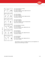
4.3.2.5 Beepfreq Route
This menu is used to set the beep frequency during the driving. The default
frequency is every 2 seconds. The frequency can be set for each route
separately. The display displays the value per second, so 0.5 equals one
beep per two seconds.
4.3.2.6 Copy Route
The menu 'Copy route' is used to copy a route. The copied route can be
modified to make a new route.
4.3.2.7 Modify Route
The menu 'Modify route' is used to modify parts of an existing route. Since a
route is built of many actions, changing one action influences the rest of the
route. Therefore modification is restricted to:
•
•
•
•
•
Description and Operation
Modify the run distance
Modify the angle of a turn
Add waiting time
Modify the feed push ultrasound distance
Modify the ultrasound distance.
4-21
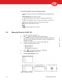
4.3.2.8 Backup Route
This menu is used to make a backup with the Lely Control app on the
smartphone or to restore the information on the ADS 3840 PCB.
4.3.2.9 Feed Groups
The menu 'Feed groups' is used to define the feed groups.
You can link a feed push action, the full action or a part of it, to a feed group.
A push power is set for each feed group.
A feed group can only be assigned to feed push actions. It is possible to use
the same feed group for more than one action.
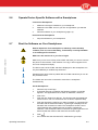
4.3.2.10 Push Power Feed Groups
The menu 'Pushpwr feedgr' is used to define the push power for the feed for
a feed group. There are four levels of push power: high, average, low and
extra low.
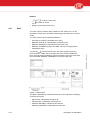
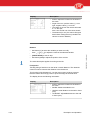
4.3.3
Settings
The menu RealTime clock is used to set the date and time of the JUNO 150.
The correct date setting is also important to search for alert reports on a
date.
Date 02-09-2008 (dd/mm/yyyy)
Time 16:53:23 (24h format, hr/min/sec)
Language
The menu Language is used to modify the language of the user interface
Gyroscope
The menu 'Gyroscope' is used to recalibrate the gyroscope. The JUNO 150
must not be moved during the calibration.
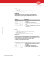
4.3.3.1 Feed Push Power
Feed push power
The menu 'Feed push power' is used to modify the force of the JUNO 150.
The menu has two sub menus:
•
•
Motor power
Auto feed push.
Motor power
The menu 'Motor power' is used to set a constant power. There are four
settings:
•
•
•
•
4-22
High
Medium
Low
Extra low.
Description and Operation
5.4301.8501.0 - Lely Control
RealTime clock
Auto feed push
The menu 'Auto feed push' is used to switch 'On' or 'Off' dynamic feed push
power.When 'Auto feed push' is switched 'On' the power is not constant but
depends on the counter-pressure of the feed. There are four settings:
•
•
•
•
High
Medium
Low
Extra low.
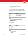
Strip width
Select the correct strip width:
•
•
•
50 mm (2.0 in)
70 mm (2.8 in)
90 mm (3.5 in).
The correct strip width for the JUNO 150 is 90 mm.
Inductor height
5.4301.8501.0 - Lely Control
Set the distance between the inductive sensor and the strip. The distance
between the inductive sensor and the strip must be minimum 10 mm (0.4 in).
Reset point
Set the sensitivity of the induction sensor to detect a reset point. There are
three settings:
•
•
•
High
Medium
Low.
Beep length
The menu Beep length is used to set the duration of the beep. The default
length is 200 mSec. This setting is for all routes.
Reset report
This menu 'Reset report' resets the service information data (service
technicians only).
Wheel diameter
Set the wheel diameter. The default value is 250 mm (9.8 in).
4.3.4
Alarms
The JUNO 150 monitors itself continuously and informs you about the
situation. The JUNO 150 generates alarms and reports.
Alarm List
The Alarm List gives a summary of the alarms received. This list stores up to
250 alarms (page 8‑1). When 250 alarms are stored, the next alarm
overwrites the oldest alarm on the list.
Report list
The Report list gives a summary of the generated reports.
Description and Operation
4-23
Info list
The Info list gives technical details. It is used by the service technician.
Reset list
The menu Reset list is used to delete all alarm, report and info information.
4.3.5
Service
The menu Service has the following submenus:
•
•
•
•
Hour counter to display the hours in use since the last counter reset (only
used by a service technician)
Version to display the software version
Installation 1 to install and test the JUNO 150 (only used by a service
technician)
Installation 2 to install and test the JUNO 150 (for development purposes
only)
Test Service to test the JUNO 150 (for development purposes only).
4.4
Operation
4.4.1
Routes, Actions, Manual Routes and Time Paths
Actions make a route
The JUNO 150 drives through a barn along a programmed route. A route is
built up of actions like 'Strip follow ' or 'Turn L <--'. A route always starts and
ends at the charging station. Refer to the following example figure (see
figure on page 4‑24).
Automatic feed pushing with a time path
The JUNO 150 pushes the feed each day automatically on the same time if
a time pathis set.
Manual feed pushing with manual routes
It is useful to enable 'MANUAL ROUTE'. You then can push a part of the
feed whenever you want to test a route (page 4‑11). It is also useful to
program routes from different points in the barn back to the charging station.
Figure 18. Actions make a route
KEY:
1. Strip follow - 2. Turn R --> - 3. Straight -4. Turn R --> - 5. Feed push L - 6. Straight - 7.
Feed push L - 8. Turn R --> - 9. Straight - 10. Turn R --> - 11. Feed push L - 12. Charger
strip
4-24
Description and Operation
5.4301.8501.0 - Lely Control
•
4.4.2
Control System
The control system keeps the vehicle on the correct route. Two sensors on
the bottom detect the metal striping on the floor. The built-in ultrasonic
sensor makes sure that the JUNO 150 follows a wall or feed fence at a predetermined distance. An electronic gyroscope guides the JUNO 150 in the
correct direction when a turn is programmed.
Driving distance
The encoders on the drive motor shafts measure the number of revolutions
of the motors. This value is used to calculate the travelled distance. If, due to
slip, the actual driving distance is less than calculated it will be corrected the
next time. It can only be corrected if the action ends at a reset point (a strip
on the floor of the feed alley).
Speed
The number of revolutions is also used to calculate the speed. The speed is
constant.
Distance to a wall or fence
5.4301.8501.0 - Lely Control
The ultrasonic sensor sends a pulsed ultrasound wave at the object and
then measures the time for the sound echo to return. Knowing the speed of
sound, the sensor can determine the distance of the JUNO 150 to a wall or
other object. The ADS 3840 PCB sends output to the drive motors to correct
the distance.
Angle
When the JUNO 150 turns, the gyroscope measures the turning angle. This
value is used to stop the vehicle turning. The turning angle may be
inaccurate if the gyroscope is not reset before starting the turn. The
gyroscope is reset each time the JUNO 150 drives a few meters in the same
direction.
Obstacles
The JUNO 150 has a rubber ring with a collision detector (see figure on
page 2‑11) that stops the vehicle immediately when the vehicle hits an object
that is at least 60 cm above floor level. The reaction of the JUNO 150
depends on the object type.
•
•
If the vehicle hits a solid object (for instance a tractor), the JUNO 150
drives back until there is no contact with the obstacle. The vehicle tries to
continue its route. If it hits the object again, it drives back again (until
there is no contact), stops and generates an alarm message.
If the vehicle hits an object that is not solid, or if a cow bites the ring, the
vehicle waits a moment and tries to continue its route. If the collision
detector is activated some more times, the vehicle stops and generates
an alarm message.
The collision detector has a pulse on it while the JUNO 150 is driving a
route.
Description and Operation
4-25
5.4301.8501.0 - Lely Control
INTENTIONALLY BLANK
4-26
Description and Operation
5.
OPERATING INSTRUCTIONS
Do not sit on the vehicle
Keep safe distance
Only persons who have read and understood all applicable safety
instructions are permitted to enter the area.
Only operate the JUNO 150 with the safety bar installed on the front.
Electric shock.
Keep away from the collision detector during operation of the JUNO 150.
5.1
Install or Update the Lely Control app on Your Smart Phone
5.4301.8501.0 - Lely Control
1.
2.
3.
4.
5.
On the smartphone go to the Google play store.
Download the Lely Control app.
Install the app.
Wait until the software is correctly installed.
The first time you start to control the JUNO 150 with the software on
the smartphone, you must enter a password for the JUNO 150
system. Ask your local Lely service provider for the password.
If there is new software available, a notification is displayed on the icon of
the Google play store.
5.2
Rename the JUNO 150 on the Smartphone
The device name of the JUNO 150 that is displayed on the smartphone can
only be modified by a certified Lely technician.
5.3
Set the farmer password
The farmer password must be set by a certified Lely technician.
It is recommended to use the same password for all smartphone controlled
machines on a farm.
Operating Instructions
5-1
5.4
Open or Close the Lid
The JUNO 150 stops immediately when the lid is opened.
Open or close the lid (see figure on page 5‑2) (1).
5.4301.8501.0 - Lely Control
1.
Figure 19. Open the lid
5.5
Switch ON or OFF the JUNO 150
The JUNO 150 does not need to be switched OFF during normal operation.
To switch ON
1.
2.
3.
Open the lid.
On the pcb box, push button [ON] to switch ON the JUNO 150.
Close the lid.
To switch OFF
4.
5.
6.
5-2
Open the lid.
On the pcb box, push button [OFF] to switch OFF the JUNO 150.
Close the lid.
Operating Instructions
5.6
Operate Device Specific Software with a Smartphone
Connect the Smartphone
1.
2.
3.
Make sure the App is installed on your smartphone.
Make sure the JUNO 150 is in your line of sight before you start the
software.
Start the software on your smartphone (page 5‑3).
Disconnect the Smartphone
1.
5.7
Stop the software on your smartphone.
Start the Software on Your Smartphone
Remote Operation of the smartphone or tablet by remote desktop
software (such as, but not limited by, Teamviewer) is strictly forbidden
to avoid dangerous situations.
Make sure the machine is in your line of sight.
5.4301.8501.0 - Lely Control
Make sure you are in the vicinity of the JUNO 150 when you want to connect
the phone to the machine. If the distance is too big, it will not appear in the
list on the smartphone display.
The device name of the JUNO 150 that is displayed on the smartphone can
only be modified by a certified Lely technician.
Sometimes the phone must be paired with the JUNO 150 before you can do
the procedure below.
The JUNO 150 can not be connected to more than 1 smartphone
simultaneously.
On the Smartphone:
1.
2.
3.
4.
5.
6.
7.
Operating Instructions
Start the Lely Control app.
If bluetooth was not in operation the following question (or similar)
appears: 'The application tries to switch on bluetooth, continue?'
Push 'Yes'.
Push the line: 'Search for devices'. The devices near the smartphone
will be found. If one or more devices are not found, repeat this step.
Push the line with the machine you want to operate. A connection will
be made with the selected machine. A green light is displayed in the
title when the connection is made. The smartphone shows a set of
control buttons and a display that can be used to operate the
software. If the smartphone loses connection the green light turns red.
Move towards the machine and make the connection again.
Push
If the JUNO 150 was switched OFF, Calibrate the gyroscope.
5-3
In general the buttons have the following function:
•
[
] Execute the command on the display above the applicable soft
button.
[START/STOP] starts or stops an action.
•
[
] moves the selector up one item or increases a value by one.
•
[
] moves the selector down one item or decreases a value by one.
•
opens the selected function or the next menu screen.
•
•
[ESC] returns to the previous screen.
reduces the speed of the vehicle.
•
Manually Drive the JUNO 150
1.
Stop all timed actions (page 5‑14).
2.
3.
Push [
4.
5.
] twice to select the menu 'Manual driving'.
The message 'SAFETY WARNING. Manual operation is permitted
only with a clear overview of the vehicle. Confirm?' appears on the
smartphone display.
Confirm if you have a clear overview of the JUNO 150.
In the menu 'Manual driving', push:
•
•
•
[L] to turn right, or
[R] to turn left, or
[L] and [R] to go straight on.
6.
Push [
] to change the direction, if necessary.
7.
8.
Push [START/STOP] to start, hold it.
Release [START/STOP] to stop.
Figure 20. Manual driving
5-4
Operating Instructions
5.4301.8501.0 - Lely Control
5.8
5.9
Drive the JUNO 150 to the Charging Station
1.
2.
3.
Stop all timed actions (page 5‑14).
Manually drive (page 5‑4) the JUNO 150 to 0.5 m (2 ft.) or less from
the strip (page 5‑4).
Make sure the front of the vehicle points in the direction of the
charging station.
4.
Push [
5.
In the menu 'Manual Charger', push:
1.
2.
6.
] to select the menu 'Manual Charger'.
[L] if the charging station is on the left side
[R] if the charging station is on the right side.
Push [START/STOP] to start.
5.4301.8501.0 - Lely Control
The JUNO 150 approaches the charging station and stops by itself.
Figure 21. Drive to the charging station
5.10
Prepare for Programming
5.10.1
Requirements for a Good Route
Make it possible for the JUNO 150 to correct itself
•
•
Remove feed and obstacles from the feed alley when programming a
route. This enables the JUNO 150 to return to the 'ideal' route when it is
forced to deviate from the route when pushing feed.
Be aware that actions like 'turn' and 'straight' may cause inaccurate
results. Make sure the vehicle cannot get stuck after making a turn or
driving straight. Program a 'long action' ('strip follow' or 'ultrasound') after
a 'short action' ('turn' or 'straight').
Make it easy for yourself
•
•
Operating Instructions
Program routes from different positions in the barn back to the charging
station. This will enable you to easily return the vehicle back to the
charging station in case it gets lost.
Make a backup after programming a route.
5-5
5.11
Program the JUNO 150
5.11.1
Program a New Route
Preparation
1.
2.
3.
4.
Make sure you understand the requirements for setting up a good
route.
Plan the route.
Open the Lely Control app on the smartphone.
Stop all timed actions (page 5‑14).
Program
In the main menu of the Lely Control app, select 'Routes' and push
[
6.
7.
8.
].
Select the menu 'New route' and push [
].
The message 'SAFETY WARNING. Manual operation is permitted
only with a clear overview of the vehicle. Confirm?' appears on the
smartphone display.
Confirm if you have a clear overview of the JUNO 150.
If the vehicle is not connected to the charging station, you can push soft
button [CHARGR] to drive the JUNO 150 to the charging station (page 5‑4).
9.
Push soft button [START].
10.
11.
12.
Read the messages on the display and push [
].
Program the first action ('Strip follow').
Program one of the next actions in the route:
•
•
•
•
•
•
•
•
Strip follow (page 5‑7)
Straight (page 5‑7)
Turn R --> (page 5‑7)
Turn L <-- (page 5‑7)
Feed push L
Ultrasound L (page 5‑9)
Charger strip (page 5‑9)
Waiting time (page 5‑9).
The actions are explained in the next section.
13.
14.
15.
5-6
If the vehicle has returned to the strip in front of the charging station,
go to the charging station (page 5‑5),
Else repeat step 6.
Push soft button [Exit].
Push soft button [Yes] to save the new route.
Operating Instructions
5.4301.8501.0 - Lely Control
5.
Close-up
16.
Test the route.
5.11.1.1 Follow the Strip on the Floor
1.
Make sure the front of the vehicle is above the metal strip on the floor.
2.
3.
Select the menu 'Strip follow' and push [
4.
5.
].
Push [START/STOP] to start.
The vehicle automatically stops at the end of the strip.
If you want the vehicle to stop, push [START/STOP].
Push soft button [Save].
5.11.1.2 Go Straight
5.4301.8501.0 - Lely Control
Before starting, make sure the JUNO 150 points in the correct direction. Use
the 'Straight' option as little as possible. If it really is necessary, for example
to pass the JUNO 150 across the feed alley, make the distance travelled as
short as possible. Continue with ' Ultrasound L'. This improves the accuracy
of the route that is travelled.
1.
2.
3.
4.
5.
Select 'Straight' and push [
].
Push [START/STOP] to start.
If you want the vehicle to stop, push [START/STOP].
Push soft button [MAN] to modify the position.
1.
Push soft button
to turn left, or
to turn right.
2.
Push [ESC] to confirm and go one level up.
Push soft button [Save].
5.11.1.3 Turn Left or Right
Operating Instructions
1.
If you want to turn left, select 'Turn L <--' and push [
2.
If you want to turn right, select 'Turn R -->' and push [
3.
Read the message on the display and push [
].
].
].
5-7
You can choose from 9 standard turns and modify the turn afterwards.
4.
5.
6.
7.
8.
Push [
] until the most appropriate standard turn is displayed, or
push [ESC] to go to the previous display.
Select one of the standard turns with the appropriate soft button.
If you want to modify the turn, push [
] or [
] to select the angle.
If you want to drive back before making a turn:
1.
Push soft button [>] to select 'Back'.
2.
Push [
] or [
] to select the reverse distance.
Push [START/STOP] to start.
If the resulting turn is not exactly as planned, modify the position (see the
next step). This is especially important if the angle is 90 or 180 degrees left
or right.
10.
Push soft button [MAN] to modify the position.
1.
Push soft button
2.
Push [ESC] to confirm and go one level up.
to turn left, or
to turn right.
Push soft button [Save].
5.11.1.4 Feed Push L
Do not program 'Feed push L' when the fence is more than 2.5 meter (8.2 ft)
away.
1.
Select the menu 'Feed push L' and push [
2.
Read the actual distance to the fence ('UltraDst') from the display.
3.
Push [
] or [
] to select the required distance to the fence
(ULTRADST:).
Push [START/STOP] to start.
If you want the vehicle to stop, push [START/STOP].
Push soft button [MAN] to modify the position.
4.
5.
6.
1.
2.
7.
5-8
Push soft button
to turn left, or
].
to turn right.
Push [ESC] to confirm and go one level up.
Push soft button [Save].
Operating Instructions
5.4301.8501.0 - Lely Control
9.
5.11.1.5 Follow a Wall or Fence on a Certain Distance (Ultrasound)
Do not program 'Ultrasound L' when the wall is more than 2 meters away.
Do not use this action to push feed.
1.
2.
3.
4.
5.
6.
7.
Select the menu 'Ultrasound Land push[
]
Read the actual distance to the wall (UltraDst) from the display.
Push [
] or [
] to select the required distance to the wall
(ULTRADST).
Push [START/STOP] to start.
If you want the vehicle to stop, push [START/STOP].
Push soft button [MAN] to modify the position.
1.
Push soft button
to turn left, or
to turn right.
2.
Push [ESC] to confirm and go one level up.
Push soft button [Save].
5.11.1.6 Go to the Charging Station following the Strip
5.4301.8501.0 - Lely Control
1.
2.
3.
Make sure the front of the vehicle is within 0.5 m (19.7 in.) from the
strip leading to the charging station, and pointing towards the
strip (page 5‑4).
Select the menu 'Charger strip'.
Push soft button [MAN] to modify the position.
1.
2.
4.
5.
Push soft button
to turn left, or
to turn right.
Push [ESC] to confirm and go one level up.
If the charging station is on the right, push soft button [L].
Push [START/STOP] to start.
The JUNO 150 approaches the charging station and stops by itself.
5.11.1.7 Waiting Time
Operating Instructions
1.
Select the menu 'Waiting time'.
2.
3.
Push[
]or [
] to select the waiting time.
Push soft button [Save].
5-9
Copy a Route
1.
2.
3.
Open (page 5‑3) the Lely Control app on the smartphone
Stop all timed actions (page 5‑14).
In the main menu of the Lely Control app, select 'Routes' and push
[
5.11.3
4.
Select 'Copy route' and push [
5.
6.
Push soft button [Yes] to confirm.
4.
Select the route you want to copy and push [
].
Open (page 5‑3) the Lely Control app on the smartphone
Stop all timed actions (page 5‑14).
Test the route.
In the main menu of the Lely Control app, select 'Routes' and push
[
].
5.
Select 'Modify route' and push [
].
6.
Select 'Modify route' and push [
].
7.
8.
Select the route you want to modify and push [
].
Read the message and make sure to understand it.
9.
Select the action you want to modify and push [
10.
If you want to add extra waiting time before the action:
11.
12.
13.
1.
2.
Select the action.
Push soft button [New].
3.
Select 'Waiting time' and push [
4.
Modify the waiting time with [
].
].
] or [
].
If you want to modify the driving distance or the turn:
Select the action and push [
].
1.
2.
Select the property you want to modify with soft button [<].
3.
Modify the value of the property with [
] or [
].
Push [ESC] to confirm and go one level up.
Push soft button [Yes] to confirm.
Reset a modified Route to the previous Version
1.
2.
3.
Open (page 5‑3) the Lely Control app on the smartphone
Stop all timed actions (page 5‑14).
In the main menu of the Lely Control app, select 'Routes' and push
[
5-10
].
Modify a Route
1.
2.
3.
5.11.4
].
5.4301.8501.0 - Lely Control
5.11.2
].
Operating Instructions
5.11.5
4.
Select 'Modify route' and push [
].
5.
Select 'Modify reset' and push [
].
6.
7.
Select the route you want to reset and push [
Push soft button Yes to confirm.
Delete a Route
1.
2.
3.
Open (page 5‑3) the Lely Control app on the smartphone
Stop all timed actions (page 5‑14).
In the main menu of the Lely Control app, select 'Routes' and push
[
5.11.6
].
].
4.
Select 'Delete route' and push [
].
5.
Select the route you want to delete and push [
6.
Push soft button [Yes] to confirm.
].
Set or Delete a Manual Route
5.4301.8501.0 - Lely Control
Set a manual route to manually drive (a set of) route(s) or to test a
route (page 4‑11).
1.
2.
3.
Open (page 5‑3) the Lely Control app on the smartphone
Stop all timed actions (page 5‑14).
In the main menu of the Lely Control app, select 'Work' and push
[
4.
].
Push [
] to select the menu 'Manual route'.
Set a Series of Routes
5.
6.
7.
8.
9.
10.
In the menu 'Manual route', push [
] to select the series of routes
you want to set (A, B, C or D).
Push soft button [>] to select the first route in the series.
Push [
] or [
] to select the route number.
Repeat step 6 and 7 to select the next route in the series (if
applicable).
Push soft button [>] twice.
Push [Save] to save the series of manual routes.
Delete a Manual Route
11.
12.
Operating Instructions
Push [
] or [
] to select the route you want to delete.
Push soft button [Reset].
5-11
5.11.7
Define Feed Groups
1.
2.
3.
Open (page 5‑3) the Lely Control app on the smartphone
Stop all timed actions (page 5‑14).
In the main menu of the Lely Control app, select 'Routes' and push
[
].
4.
Select 'Feed groups' and push [
5.
6.
7.
Select the route and push [
8.
Use buttons [
button [>].
].
].
Select the feed push action you want to define a feed group to.
Select soft button [>]. 'Default' starts to blink.
] or [
] to select the feed group and push soft
9.
To use the full length of the push action for this feed group, push
10.
[
].
To use more than one feed groups for the feed push action:
1.
Push soft button [>].
2.
Use button [
] and [
] to change the length of the feed
group and push soft button [>].
When you push soft button [SAVE ], a new default row is added
with the remaining distance.
Select soft button [>]. 'Default' starts to blink.
3.
4.
Use buttons [
] or [
] to select the feed group and push
soft button [>].
Do the previous steps if you want to add another feed group to
this feed push action.
5.
6.
The total length of the feed groups must be equal to the length of the feed
push action.
11.
5.11.8
Push [ESC] and push soft button [...save...].
Define the Push Power for a Feed Group
1.
2.
Open (page 5‑3) the Lely Control app on the smartphone
Stop all timed actions (page 5‑14).
3.
In the main menu of the Lely Control app, select 'Routes' and push
[
5-12
].
Operating Instructions
5.4301.8501.0 - Lely Control
Up to 20 feed groups can be used.
5.11.9
4.
Select 'Feed push power' and push [
].
5.
Select the applicable feed group and push [
6.
7.
Select the applicable push power and push [
1.
2.
Open (page 5‑3) the Lely Control app on the smartphone
Stop all timed actions (page 5‑14).
In the main menu of the Lely Control app, select 'Routes' and push
].
].
Push button [ESC].
Set a Time Path
3.
[
4.
].
Select 'time path' and push [
].
Refer to the time path description.
5.4301.8501.0 - Lely Control
The JUNO 150 must not drive more than 40% of the total time in a time path.
It must spend minimum 60% of the total time charging at the charging
station.
5.
6.
Push soft button [New].
Push soft button [>].
7.
Push [
] to select the start time (hour) and push soft button [>].
8.
Push [
] to select the start time (minutes) and push soft button [>].
9.
Push [
] to select the route and push soft button [>].
10.
If you want:
•
•
11.
5.11.10
To add another route to the time path, push soft button [New] and
repeat steps 7 to 11
Confirm an go up one level, push [ESC].
Push soft button [Yes] to save the new time path.
Make a Backup
Make a backup each time you change a route or time path or when another
smartphone is used. Backups are made on the smartphone.
Make sure to give each backup you make a unique name.
Make sure the phone has a proper connection with the JUNO 150 and has
enough storage space available for the backup file.
Operating Instructions
5-13
To make a Backup
1.
2.
Stop all timed actions (page 5‑14).
In the main menu of the Lely Control app, select 'Routes' and push
[
3.
4.
5.
6.
7.
8.
Copy a Backup file from the Smartphone to a PC
1.
2.
3.
4.
5.
5.11.12
Connect the smartphone to a usb port of the PC. Use the data cable
of the smartphone to connect.
Use the PC to browse to the Lely backup folder on the smartphone.
Select the applicable backup file (.bkp).
Copy the backup file from the smartphone.
Paste the backup file to the pc.
Copy a Backup file from a PC to the Smartphone
1.
2.
3.
4.
5.12
Select 'Backup route' and push [
]. The question 'Backup or restore
the current routes and settings? ' appears on the display of the
smartphone.
Push soft button [Bckup]. The software asks if you want to make a
backup on the smartphone.
Push soft button [Yes]. The smartphone displays a progress bar of the
backup process.
Enter the name for the backup file.
Push soft button [OK]
Wait until the process ends with a beep.
Connect the smartphone to a usb port of the PC. Use the data cable
of the smartphone to connect.
Use the PC to browse to the location of the backup file (.bkp).
Copy the backup file from the PC.
Paste the backup file to the Lely backup folder on the smartphone.
Start or Stop Timed Actions
Remote Operation of the smartphone or tablet by remote desktop
software (such as, but not limited by, Teamviewer) is strictly forbidden
to avoid dangerous situations.
1.
Open (page 5‑3) the Lely Control app on the smartphone
2.
In the main menu of the Lely Control app, select 'Work' and push
[
5-14
].
Operating Instructions
5.4301.8501.0 - Lely Control
5.11.11
].
If the pane on the upper side of the menu, that displays the actual time, is
grayed out, the timed actions are ON.
3.
4.
Push [START/STOP]. Or
Push the pause button on the JUNO 150 to start/stop the timed
actions of the JUNO 150.
Figure 22. Start or stop timed actions
5.13
Start, Stop or Pause a Manual Route
Remote Operation of the smartphone or tablet by remote desktop
software (such as, but not limited by, Teamviewer) is strictly forbidden
to avoid dangerous situations.
5.4301.8501.0 - Lely Control
To start a manual route:
1.
Stop all timed actions (page 5‑14).
2.
In the main menu of the Lely Control app, select 'Work' and push
[
].
3.
Push [
] to select the menu 'Manual route'.
4.
5.
6.
Push [
] to select the series of routes (A, B, C or D).
Push [START/STOP].
If you want to switch ON the time path after the manual route, push
soft button [Yes],
Else push soft button [No].
To pause or stop a manual route:
1.
2.
Push [START/STOP] or the pause button on the JUNO 150.
If you want to:
•
Stop the route immediately, push soft button [Yes].
•
Resume the route, push soft button [No] or the pause button on the
JUNO 150.
Pause,
•
3.
Operating Instructions
1.
Push soft button [Pause].
2.
Push button [
pause.
] to select the number of minutes you want to
Push soft button [OK].
5-15
Figure 23. Start a manual route
Block a Route
1.
2.
Stop all timed actions (page 5‑14).
In the main menu of the Lely Control app, select 'Routes' and push
[
].
3.
Select 'Blockage route' and push [
].
4.
Push [
5.
Push [
] to block the route (value 1) and push [ESC] to confirm and
go one level up.
] to select the route that you want to block and push [
].
Blocking a route has no effect on Manual Route (page 5‑15).
5.15
Reset the Emergency Stop Button
1.
5-16
Turn the button counter clockwise and pull it out until it unlocks (see
figure on page 2‑11).
Operating Instructions
5.4301.8501.0 - Lely Control
5.14
6.
6.1
MAINTENANCE
Introduction
This chapter contains the preventive maintenance schedule and the
applicable preventive maintenance procedures for the JUNO 150. It also
contains some basic corrective maintenance procedures.
6.2
Preventive Maintenance Schedule
The following table shows the preventive maintenance schedule for the
JUNO 150. Preventive maintenance must obey local regulations, if
applicable.
The frequencies of the tasks shown in the table are the minimum
frequencies recommended.
5.4301.8501.0 - Lely Control
Maintenance Tasks
Frequencies
Operating
Months
Clean the charging strips (page 6‑5)
1
Clean the charging electrodes on the charge
unit (page 6‑5)
1
Check the battery is charging (page 7‑4)
1
Adjust the skirt height (page 6‑6)
4
6.3
Preparation
6.3.1
Break or close the Power Circuit
Operating
Years
Note
If the feed alley is not clean
enough
To break the power circuit
1.
Loosen the knob on the battery stop (see figure on page 6‑2) (1).
To close the power circuit
2.
Maintenance
Fasten the knob on the battery stop.
6-1
Figure 24. Break the Power Circuit
Remove or Install the Cover
Removal
1.
2.
3.
Open the lid(1).
Loosen the two elastic fasteners (2) on the inside of the cover that
attaches it to the frame.
Remove the cover (3).
Installation
4.
5.
6-2
Install the cover (3).
Install the two elastic fasteners (2).
Maintenance
5.4301.8501.0 - Lely Control
6.3.2
5.4301.8501.0 - Lely Control
Figure 25. Open the lid. Remove the fasteners
Maintenance
6-3
5.4301.8501.0 - Lely Control
Figure 26. Remove the cover of the motor room
6.3.3
Switch OFF or ON the JUNO 150
The JUNO 150 does not need to be switched OFF during normal operation.
To switch OFF
1.
2.
3.
Open the lid.
On the PCB-box, push the button [OFF] to take the JUNO 150 out of
operation (page 4‑4).
Close the lid.
To switch ON
4.
5.
6.
6-4
Open the lid.
On the PCB-box push the button [ON] to switch ON the JUNO
150 (page 4‑4).
Close the lid.
Maintenance
6.4
Maintenance Procedures
Danger of being entangled by rotating parts.
Keep hands, loose clothing, and long hair away from moving parts
during operation of the JUNO 150.
6.4.1
Clean the Charging Strips and the Charging Electrodes
Make sure that after cleaning the charging electrodes slide over the
middle of the charging strips when the JUNO 150 parks.
Preparation
1.
2.
Disconnect the main power supply to the charging station.
Manually drive the JUNO 150 to a clean and quiet location (page 5‑4).
5.4301.8501.0 - Lely Control
Clean
3.
Thoroughly clean the charging strips (see figure on page 6‑6) (1) of
the JUNO 150 with sand paper.
4.
Thoroughly clean both electrodes of the charging station (2) with a
brush or sand paper.
Close-up
5.
6.
7.
8.
Maintenance
Connect the charging station to the main power supply.
Manually drive the JUNO 150 to the charging station.
Examine the charging electrodes slide over the middle of the charging
strips when you park the JUNO 150.
Start the timed actions (page 5‑14).
6-5
5.4301.8501.0 - Lely Control
Figure 27. Clean the charging strips and electrodes
6.4.2
Adjust the Skirt Height
Preparation
1.
2.
3.
4.
Manually drive the JUNO 150 to a clean and quiet location (page 5‑4).
Remove the cover.
Switch OFF the JUNO 150 (page 6‑4).
Break the power circuit.
Adjust
5.
6.
7.
8.
Loosen the knob (see figure on page 6‑7) (3)
Turn the handle (1) until the skirt on the side of the feed fence (2) and
on the front side (4) reaches the floor.
Fasten the knob.
Make sure the height of the lower charging strip is 76.5 cm (30.1 in.).
Close-up
9.
10.
11.
6-6
Close the power circuit.
Put the JUNO 150 in operation (page 6‑4).
Install the cover.
Maintenance
12.
13.
14.
15.
Open the Lely Control app on the smartphone.
Manually drive the JUNO 150 to the charging station (page 5‑5).
Make sure the charging strips of the JUNO 150 make good contact
with the electrodes.
Start the timed actions (page 5‑14).
5.4301.8501.0 - Lely Control
1
4
2
3
Figure 28. Set the skirt height (without cover)
KEY:
1. Handle - 2. Feed fence side of the skirt - 3. Knob - 4. Front side of the skirt
Maintenance
6-7
5.4301.8501.0 - Lely Control
INTENTIONALLY BLANK
6-8
Maintenance
7.
7.1
TEST AND ADJUSTMENT
Introduction
This chapter contains the test- and adjustment procedures for the JUNO 150
Feed Pusher.
Several options shown on the display of the user interface are not relevant
for standard test and adjustment procedures, but may be useful for
troubleshooting by the service provider.
Settings
7.2.1
Set the Real-Time Clock
5.4301.8501.0 - Lely Control
7.2
1.
Open (page 5‑3) the Lely Control app on the smartphone
2.
In the main menu select 'Settings' and push [
3.
In the menu 'Settings', select 'RealTime clock'and push [
4.
Push soft button [
].
].
] to select a menu item.
The real-time clock has a 24 hour format. For instance 7:00 is not the same
as 19:00.
5.
6.
7.2.2
Push [
] or [
] to increase or decrease the value of the selected
option.
Push [ESC] to confirm and go one level up.
Set the Display Language
1.
2.
Open (page 5‑3) the Lely Control app on the smartphone
In the main menu of the Lely Control app, select 'Settings' and push
[
Test and Adjustment
].
3.
Select 'Language' and push [
4.
5.
Push [ESC] to confirm and go one level up.
Push [
] or [
].
] to select the display language.
7-1
7.2.3
Modify the Beep Frequency for a Route
1.
2.
Open (page 5‑3) the Lely Control app on the smartphone
In the main menu of the Lely Control app, select 'Routes' and push
[
].
3.
Select 'Beepfreq route' and push [
4.
Select the route you want to modify and push [
5.
Push [
] or [
].
].
] to modify the number of beeps per second.
The standard value 0.5 equals one beep per two seconds.
6.
Modify the Beep Length
1.
2.
Open (page 5‑3) the Lely Control app on the smartphone
In the main menu of the Lely Control app, select 'Settings' and push
3.
[
].
Select 'Beep length'.
4.
Push [
] or [
5.4301.8501.0 - Lely Control
7.2.4
Push [ESC] to confirm and go one level up.
] to modify the length.
The standard value is 200 mSec.
5.
7.2.5
Modify the Feed Push Power
1.
2.
Open (page 5‑3) the Lely Control app on the smartphone
In the main menu of the Lely Control app, select 'Settings' and push
3.
].
[
Select 'Feed push power'.
4.
5.
7-2
Push [ESC] to confirm and go one level up.
Push [
] or [
] to modify the power.
Push [ESC] to confirm and go one level up.
Test and Adjustment
7.3
Tests
7.3.1
Analyse the Reliability of a Route
1.
2.
3.
Open (page 5‑3) the Lely Control app on the smartphone
Stop all timed actions (page 5‑14).
In the main menu of the Lely Control app, select 'Routes' and push
[
4.
Select 'Route analysis' and push [
5.
Select 'Fail. problty' and push [
6.
5.4301.8501.0 - Lely Control
Find out the cause of the unreliability.
Modify the route.
Repeat steps 5 to 7.
If the route is still not reliable:
1.
2.
Delete the route.
Make a new route.
Test a Route
1.
2.
3.
4.
7.3.3
].
If a route has a failure probability of more than 2,
1.
2.
7.
8.
].
] or [ESC] to display routes that are not displayed.
Push [
7.3.2
].
Put the route into a manual route.
Start the manual route (page 5‑15).
Find the actions and action numbers on the display of the user
interface of the Lely Control app.
Make sure the route is correct.
Make sure the Battery is Loaded
1.
2.
Stop all timed actions (page 5‑14).
In the main menu of the Lely Control app, select 'Work' and push
3.
4.
[
].
Make sure the battery voltage is more than 12500 mV (fig. 1).
If the voltage is less than 12500 mV:
1.
2.
5.
Test and Adjustment
Manually drive the JUNO 150 to the charging station.
Make sure the battery is charging (page 7‑4).
Charge the battery for one hour.
7-3
Figure 29. Battery voltage
Make sure the Battery is Charging
1.
2.
Make sure the JUNO 150 is connected to the charging station.
Stop all timed actions (page 5‑14).
3.
In the main menu of the Lely Control app, select 'Work' and push
4.
5.
6.
7.
8.
9.
10.
11.
[
]. (three times).
Make sure the menu MANUAL CHARGER is displayed.
Make sure the charging current is more than 1.0 A.
If the charging current is less than 1.0 A, make sure the orange LED
on the charging station is ON.
If not, make sure the main power is connected to the battery charger.
If the JUNO 150 is still not charging, make sure the electrodes are
connected to the battery charger.
If the JUNO 150 is still not charging, clean the charging strips and the
electrodes (page 6‑5).
If the JUNO 150 is still not charging, make sure all power connections
are connected properly.
If the JUNO 150 is still not charging, call the local service provider.
Figure 30. Battery charging current
7.3.5
Make sure the Bluetooth Connection is Reliable
1.
2.
Start the Lely Control app on the smartphone.
Connect the smartphone to the JUNO 150.
3.
4.
5.
Push the button 'Settings' at the bottom of the smartphone display.
Select 'Signal Strength'.
Examine the value of the signal of the JUNO 150.
•
•
•
7-4
0 = very good
-20 - -25 = poor
< -25 = very bad
Test and Adjustment
5.4301.8501.0 - Lely Control
7.3.4
7.3.6
Test the Ultrasonic Sensor
Test
1.
2.
Manually drive the JUNO 150 to a location more than 6 m (6.6 yrd)
from a wall.
Make sure no object is between the ultrasonic sensor and the wall.
3.
In the main menu of the Lely Control app select 'Test' and push [
4.
5.
Select 'Ultrasound' and push [
6.
].
].
If the ultrasonic sensor is on the left, push soft button [L], else push
[R].
Make sure the JUNO 150 is between you and the wall.
5.4301.8501.0 - Lely Control
Make sure not to interrupt the sensing beam.
7.
8.
Monitor the display of the user interface.
Make sure the 'Puls 1', 'Puls 2', 'Puls 3' and 'Filter' values are 0.
9.
10.
11.
12.
If the values are not 0, clean the ultrasonic sensor with a tissue.
Repeat the steps 7 and 8.
If the values are not 0, call your local Lely service provider.
If the puls and filter values are 0,
1.
2.
Put an object exactly 1 m. (1.1 yrd) from the ultrasonic sensor.
Make sure the Puls 1 and Filter show 1000 (mm).
Else call your local service provider.
Close-up
13.
14.
Manually drive the JUNO 150 to the charging station.
Start the timed actions (page 5‑14).
Figure 31. Test the ultrasonic sensor
Test and Adjustment
7-5
5.4301.8501.0 - Lely Control
INTENTIONALLY BLANK
7-6
Test and Adjustment
8.
8.1
TROUBLESHOOTING
Introduction
This chapter contains the troubleshooting procedures for the JUNO 150.
•
•
•
8.2
Alarms and reports
Troubleshooting table
Recovery procedures.
Alarms and Reports
The JUNO 150 Feed Pusher monitors itself continuously. As soon as it
detects an error it generates a message, the system also generates and
displays reports with important information:
5.4301.8501.0 - Lely Control
•
•
A critical alarm message: 3 beeps sound and the JUNO 150 stops
functioning. The user interface on the smartphone displays the message
"ALARM" with a description (page 8‑1). The error requires an error
recovery procedure.
A non-critical report is recorded in the report list, the JUNO 150 continues
functioning.
The system also displays information about the operation of the JUNO 150.
8.2.1
Recover alarms
Confirm an alarm
When the JUNO 150 is in normal operation and a critical alarm occurs:
•
•
•
An alarm message is displayed on the smartphone.
The LED in the pause button on the JUNO 150 blinks.
An alarm sounds.
To recover the critical alarm:
1.
Press any key on the smartphone to accept the alarm. The alarm
sound stops. The LED in the pause button turns on.
When the alarm:
•
•
Troubleshooting
Is caused by the emergency stop button or
The collision detector while the motors ran too long after the alarm was
caused
8-1
The LED in the pause button still blinks. On the smartphone the message
'Push the pause button to release the safety circuit' is displayed.
2.
Push the pause button on the JUNO 150. The JUNO 150 goes into
pause mode. The LED in the pause button is continuously on.
'Continue with current route?' is displayed on the smartphone.
Continue normal operation
When the alarm is confirmed, on the smartphone press:
•
[Yes] to continue the current route.
Or:
[No] to go to the main menu.
1.
2.
3.
Select 'Alarms' > 'Alarm List'. The display displays the number, the
date and time when the alarm occurred and the alarm number, see
the example below.
Note the alarm number and refer to the alarm list (page 8‑1).
Do the recovery procedure described in the alarm list.
No.
Date
Time
Alarm
1
4-1
22:17
7
2
4-1
21:33
10
Select an alarm in the list and push [
extra information.
] to open the alarm message for
Or:
•
[MAN] to put the JUNO 150 in a proper position to continue with the
current route. The message 'SAFETY WARNING. Manual operation is
permitted only with a clear overview of the vehicle. Confirm?' appears on
the smartphone display.
1.
2.
8.2.2
Confirm if you have a clear overview of the JUNO 150.
Press 'Esc' > [Yes] to continue with the current route.
Alarm List
The table below gives the alarm numbers and any actions to be taken:
8-2
Troubleshooting
5.4301.8501.0 - Lely Control
•
Alarm Alarm message
code
1
Description / cause
EMPTY_BATTER •
Y
"Battery power
too low to start
•
route, charge first!
"
Bad contact with battery
charger due to dirt and/or
corrosion.
Loose connections.
Recovery procedure
1.
2.
3.
4.
JUN_OFF_RANG •
E
Juno lost ->
•
searching reset
point (strip)
Test the inductive
sensors
JUNO 150 should have
passed reset strip.
Incorrect height inductive
sensor.
4
TURN BLOCK
Juno can not
make the turn!
Mechanical problem, worn
1.
parts, dirt causing resistance 2.
Turn action to difficult
5.4301.8501.0 - Lely Control
3
•
•
1.
3.
4.
5
NO TIME
No active time!
6
BLOCKAGE_JUN •
Juno blocked!!
•
•
Call your local Lely service provider.
Make sure there are no obstacles.
Make sure the rotating skirt is free to
rotate. If not, call your local Lely service
provider.
Make sure the rubber skirt is not worn. If
the rubber skirt is worn out, call your local
Lely service provider.
Analyse the route and make a more
reliable route if necessary (page 7‑3).
5.
If the problem remains, call your local Lely
service provider.
Time path is empty
1.
Set the time path and try
again (page 5‑13).
Obstacle
Gyroscope inaccurate
1.
2.
3.
Make sure there are no obstacles.
Try to run the route again.
If the JUNO 150 is blocked by the forage,
make routes with smaller intervals.
If the JUNO 150 is blocked at a different
place, calibrate the gyroscope (page 8‑
19).
4.
Troubleshooting
Clean the charging strips and the charging
electrodes (page 6‑5).
Manually drive the JUNO 150 to the
charging station (page 5‑5).
Make sure the battery is
charging (page 7‑4).
If the problem remains, call your local Lely
service provider.
8-3
JUNO_LOST
Juno deviates
from correct
directn!
- obstacle
- gyro drifting
- bend in route
1.
2.
3.
4.
5.
Make sure there are no obstacles.
Calibrate the gyroscope (page 8‑19).
Test the ultrasonic sensor.
Start the timed actions (page 5‑14).
If the problem remains:
1.
Analyse the route and make a more
reliable route if necessary (page 7‑3).
1.
8
TURN ERROR
Juno turns more
than 360 deg!
- Check
gyroscope
- Calibrate via
menu Settings
9
LOADING
No charging
current! Check
charge strips for
dirt
•
JUNO 150 does not reach
the charging station.
1.
2.
Calibrate the gyroscope (page 8‑19).
If the problem remains, call your local Lely
service provider.
1.
Clean the charging strips and the charging
electrodes (page 6‑5).
Manually drive the JUNO 150 to the
charging station (page 5‑5).
Make sure the battery is
charging (page 7‑4).
If the problem remains, call your local Lely
service provider.
2.
3.
4.
10
STARTUP
•
Alarm appears with every
startup of the JUNO 150. For
information only.
11
ROUTEMEMORY
Route memory is
full. First delete
one route!!
•
Route memory has reached
the maximum of 16 different
routes.
12
NO_ULTRASIGN •
No ultrasound
•
signal:
- dirt on sensor
•
- no object
8-4
If the problem remains, call your local
Lely service provider.
1.
Delete a route prior to programming a new
one.
Dirt on the ultrasonic sensor 1.
No object within reach of the 2.
sensor.
3.
Sensor broken.
Clean the ultrasonic sensor.
Test the ultrasonic sensor. (page 7‑5)
If the problem remains, call your local Lely
service provider.
Troubleshooting
5.4301.8501.0 - Lely Control
7
13
BENDSKIDDING
Juno skid in the
turn!
1.
2.
3.
5.4301.8501.0 - Lely Control
4.
5.
14
EXTRA
CHARGE1
•
Voltage is too low, the JUNO
150 charges for an extra
hour. For information only.
15
EXTRA
CHARGE2
•
The JUNO 150 charges for
an extra hour. For
information only.
16
EXTRA READY1 •
Recharging is complete. For
information only.
17
EXTRA READY2 •
Recharging is complete. For
information only.
18
CHARG
•
TIMEOUT
Timeout charger:
battery not
charging! Check
charge LEDs on
charger and clean
charge strips
Battery not full despite
charging.
1.
2.
3.
4.
Make sure the floor is not slippery.
Make sure the wheels are not worn out. If
the wheels are worn out, call your local
lely service provider.
Make sure the rubber skirt is not worn out.
If the rubber skirt is worn out, call your
local Lely service provider.
Manually run the route again (page 5‑15).
If the problem remains, call your local Lely
service provider.
Clean the charging strips and the charging
electrodes (page 6‑5).
Manually drive the JUNO 150 to the
charging station (page 5‑5).
Make sure the battery is
charging (page 7‑4).
If the problem remains, call your local Lely
service provider.
19
DOUBLE TIME
Similar points in
time exist!
1.
Correct the start and end times in the time
path (page 5‑13).
20
BATTVOLT LOW
Battery power too
low to start route!
Drive JUNO 150
to charger or
clean charge
strips!
1.
Clean the charging strips and the charging
electrodes (page 6‑5).
Manually drive the JUNO 150 to the
charging station (page 5‑5).
Make sure the battery is
charging (page 7‑4). Put the JUNO 150 in
operation. If the battery is charged
sufficiently, the JUNO 150 will continue
automatic operation.
If the problem remains, call your local Lely
service provider.
2.
3.
4.
Troubleshooting
8-5
SKIDDING. WFL •
The JUNO 150 skids too much. 1.
2.
3.
22
SKIDDING_STO •
P
Juno skids!
The JUNO 150 stopped
because alarm 13 was
generated five times.
1.
2.
3.
23
HEAVY DRIVE
Juno drives
hard!!
•
The JUNO 150 has difficulties
driving the route.
Make sure the floor is not slippery.
Make sure the wheels are not worn out.
If the wheels are worn out, call your local
lely service provider.
Test the route (page 7‑3).
Make sure the rubber skirt is not worn or
damaged. If the rubber skirt is worn out,
call your local lely service provider.
Manually run the route
again (page 5‑15).
If the problem remains, call your local
Lely service provider.
If the alarm is repeated more that 5 times per
week:
1.
2.
3.
Make sure there are no obstacles.
Make sure the driving distance from the
feed fence is different each route.
If the problem remains:
1.
Analyse the route and make a more
reliable route if necessary (page 7‑3).
24
FLASH-ERROR •
Flash error!!
Flash memory communication
error.
1.
Call your local Lely service provider.
25
SHORT-CIR. 1L •
Short-circuit
motor 1 Left
wheel
Short circuit in the left motor,
the cables or the pcb.
1.
Call your local Lely service provider.
26
SHORT-CIR. 2R •
Short-circuit
motor 2 Right
wheel
Short circuit in the right motor,
the cables or the pcb.
1.
Call your local Lely service provider.
27
BACKUP
ERROR
Error backup:
Try again!
Smartphone not properly
connected
Software on the smartphone is
not correct
Smartphone is broken
Not enough storage space
available
1.
Make sure the smartphone is connected
properly via bluetooth.
Make sure to use the correct
version (page ‑1) of the Lely Control
app.
Free up storage space.
Try to make another
backup (page 5‑13).
If the problem remains, call your local
Lely service provider.
•
•
•
•
2.
3.
4.
5.
8-6
Troubleshooting
5.4301.8501.0 - Lely Control
21
5.4301.8501.0 - Lely Control
29
NO_GYRO_STA •
RT
Factory startup
gyro failed!
Cooldown gyro
and startup gyro
again
Factory calibration failed.
1.
Call your local Lely service provider.
30
M1 THERMISCH •
Motor 1 thermic
out
Current left motor too high,
probably due to dirt or worn
parts.
1.
2.
Remove any dirt or obstacles.
Call your local Lely service provider.
31
M2 THERMISCH •
Motor 2 thermic
out
Current right motor too high,
probably due to dirt or worn
parts.
1.
2.
Remove any dirt or obstacles
Call your local Lely service provider.
32
COOL DOWN
•
Gyro is too hot to
do a factory
startup. Let gyro
cool down first
The JUNO 150 pauses to cool
down the motors.
For information only.
33
FULL
CHARGING
•
The JUNO 150 must charge
fully during nighttime.
1.
34
BATT FULL
Battery is full. For information only.
35
BATT ERROR
•
•
•
36
NO_GYRO_STA
RT
Gyroscope does
not startup
correct!
37
GYRO
•
ANGLEFACT
Angle calibration
gyro not correct
Troubleshooting
Battery recharge failed,
1.
charging current too low.
Bad contact with battery
2.
charger due to dirt or corrosion.
Loose connections
3.
Gyroscope angle not
calibrated.
Modify the time path: provide more
charging time (max. 40% drive time).
4.
Make sure the mains voltage is correct
for the battery charger.
Clean the charging strips and the
charging electrodes (page 6‑5).
Make sure the battery is
charging (page 7‑4).
Charge the JUNO 150.
1.
Call your local Lely service provider.
1.
Call your local Lely service provider.
8-7
38
LOADING
•
No charging
current! Check
•
charge strips for
dirt
Bad contact with battery
1.
charger due to dirt or corrosion.
Loose connections.
2.
Clean the charging strips and the
charging electrodes (page 6‑5).
Make sure the battery is
charging (page 7‑4).
39
GYRO_TEMP
Gyroscope not
on temperature!
Check power
supply
Gyroscope startup calibration is 1.
not done.
Calibrate the gyroscope (page 8‑19).
40
CAL_IND_ZERO
1.
Call your local Lely service provider.
•
Inductive sensor
values not
correct --> much
deviation!!
Are the sensors
above guide
strip?
GYROANGLEFA •
CT
Angle calibration
gyro not correct.
Calibration
values gyro not
correct! -not
exactly 5 turns gyro drifts calibrate gyro
Gyroscope angle not
calibrated.
1.
Call your local Lely service provider.
42
CALIBR_I_PCB •
Calibrate voltage
PCB not good ->
deviation too
high!
Error during calibration
1.
Call your local Lely service provider.
43
BATTERY_STO •
P
Juno battery
•
runs down.
Switch off or
•
charge Juno
More than 24 hours not
charged.
The JUNO 150 started a route
when not on charger.
The JUNO 150 stops and
beeps for 1 hour.
Time path is started.
1.
Clean the charging strips and the
charging electrodes (page 6‑5).
Manually drive the JUNO 150 to the
charging station (page 5‑5).
Make sure the battery is
charging (page 7‑4).
Charge the JUNO 150 (page 8‑19).
Start the time path (page 5‑14).
•
8-8
5.4301.8501.0 - Lely Control
41
2.
3.
4.
5.
Troubleshooting
5.4301.8501.0 - Lely Control
44
BATT_FATAL_E
R
FATAL ERROR!
Battery becomes
overloaded.
Remove Juno
from loader Call
Lely!
1.
Call your local Lely service provider.
45
GYRO_TYPE
1.
Call you local Lely service provider.
46
GYRO_AUTOCA This alarm appears with every
L
successful autocalibration of the
Auto calibration gyroscope. For information only.
of the gyro is
finished
47
GYRO_AUTOST
OP
Auto calibration
of gyroscope is
interrupted!
Calibrate
gyroscope
(menu Settings)
1.
2.
Calibrate the gyroscope (page 8‑19).
If the problem remains, call your local
Lely service provider.
48
BATTERY_OFF •
1.
Clean the charging strips and the
charging electrodes (page 6‑5).
Manually drive the JUNO 150 to the
charging station (page 5‑5).
Make sure the battery is
charging (page 7‑4).
After 1 hour of alarm #43, the
JUNO 150 will power off to
protect the battery.
2.
3.
49
BATTERY_CAB •
LE
Loader error!
Check cable
connections
50
DIRECTION_JU
N
Juno not in
correct direction!
- obstacle
- gyro drifting
- bend in action
Charging current not available
when starting test route.
1.
.Call your local Lely service provider.
1.
2.
3.
4.
5.
Make sure there are no obstacles.
Calibrate the gyroscope (page 8‑19).
Test the ultrasonic sensor (page 7‑5).
Start the timed actions.
If the problem remains:
1.
Analyse the route and make a more
reliable route if necessary (page 7‑3).
1.
Troubleshooting
If the problem remains, call your
local Lely service provider.
8-9
NOT_IND_ZER
O
Inductive
sensors not
calibrated!!
52
ULTRAS_CALIB •
53
CALIBR_I_PCB
54
CLOCK ERROR •
The 24 hours
clock is not
correct -> adjust
the time!!
Start pulse ultrasonic sensor
not calibrated.
Internal clock is not set.
1.
Call your local Lely service provider.
1.
Call you local Lely service provider.
1.
Call you local Lely service provider.
1.
Make sure the real-time clock is set in
the correct 24 hour format (page 7‑1).
Make sure all start and end times in the
time path are entered in the correct 24
hour format (page 7‑1).
Set the real-time clock (page 7‑1).
Adjust the start and end times if
necessary (page 5‑13).
2.
3.
4.
55
BACKUP
ERROR2
56
1.
Make a Backup (page 5‑13).
SHORT-CIR. 34
Shortcut on
motor #3 & #4
connectors
1.
Call you local Lely service provider.
57
GYRO_SPI
1.
Call you local Lely service provider.
58
GYRO_I_INSTA
B
1.
Call you local Lely service provider.
59
GYRO_TIMEOU
T
1.
Call you local Lely service provider.
60
GYRO BIAS1
Gyrovalue drifts
- Try again after
10 sec
- Calibrate via
menu Settings
1.
Call you local Lely service provider.
61-64 GYRO BIAS2 - 5
Gyro value drifts
Juno
automatically
starts route!
1.
Call you local Lely service provider.
65
GYRO_TYPE
1.
Call you local Lely service provider.
66
GYRO_I_NOT 0
1.
Call you local Lely service provider.
8-10
•
No backup on the smartphone
Troubleshooting
5.4301.8501.0 - Lely Control
51
71
BLOCKAGE_JU •
NO Juno
•
blocked!!
Obstacle.
Gyroscope inaccurate.
1.
2.
3.
4.
73
NO_ULTRASIG
N
•
5.4301.8501.0 - Lely Control
•
•
•
Make sure there are no obstacles.
Try to run the route again.
If the JUNO 150 is blocked by the
forage, make routes with smaller
intervals.
If the JUNO 150 is blocked at a different
place, calibrate the gyroscope (page 8‑
19).
No signal from the ultrasonic
sensor.
Dirt on sensor.
No object.
No signal during 1,5 seconds.
1.
2.
Clean the ultrasonic sensor.
Test the ultrasonic sensor (page 7‑5).
77
EXTRA
CHARG3
•
Battery JUNO 150 has
insufficient capacity to
complete the route
1.
The route starts automatically when the
battery is charged.
78
EXTRA READY3 •
Battery JUNO 150 has
insufficient capacity to
complete the route
1.
The route starts automatically when the
battery is charged.
79
JUNO_SLIP
The JUNO 150 slips during a
route action.
1.
2.
Make sure the floor is not slippery.
Make sure the wheels are not worn out.
If the wheels are worn out, call your local
lely service provider.
Test the route (page 7‑3).
If the problem remains, decrease the
motor power (page 4‑22).
•
3.
4.
80
EMERG_BUTTO
N
Emergency stop
button pushed!!
Reset the
emergency stop
button
81
COLL_DET_ST •
OP
•
Collision detector
activated!
82
EMERG_BUTTO
N
Emergency stop
button pushed!!
Reset the
emergency stop
button
Troubleshooting
1.
2.
Wire damage
Internal damage collision
sensor.
1.
1.
2.
Reset the emergency stop
button (page 5‑16).
Start the timed actions (page 5‑14).
Make sure there are no obstacles.
Reset the emergency stop
button (page 5‑16).
Start the timed actions (page 5‑14).
8-11
83
COLL_DET_ST
OP
Collision detector
activated!
1.
Make sure there are no obstacles.
84
EMERG_HARD
WRE
Hardware safety
protection!
Circuit
interrupted!!
Call Lely!
1.
Call you local Lely service provider.
85
LID OPEN
Lid open protection!
PROT
Lid must be closed when the Juno 1.
2.
drives!
Lid open
3.
protection!
Lid must be
closed when the
Juno drives!
LID OPEN
Lid open protection!
PROT
Lid must be closed when the Juno 1.
2.
drives!
Lid open
3.
protection!
Lid must be
closed when the
Juno drives!
].
Push soft button Yes to continue.
Close the lid.
Push [
].
Push soft button [Yes] to continue.
Close the lid.
87
EMERG_CIRC1
1.
Call you local Lely service provider.
88
EMERG_CIRC2
1.
Call you local Lely service provider.
89
FPGA_ERROR
1.
Call you local Lely service provider.
1.
Call your local Lely service provider.
1.
Make sure there are no obstacles.
1.
2.
Make sure there are no obstacles.
If the problem remains, call your local
Lely service provider.
FGPA does not
start!! Reset
PCB
90-98 Software 1-9
Software
FAILURE Call
Lely!
99
COLL_DET_ST •
OP
Collision detector
activated!
100
COLL_DET_ST
OP
Collision detector
activated!
8-12
The JUNO 150 collided
Troubleshooting
5.4301.8501.0 - Lely Control
86
Push [
101
102
125
8.2.3
NO STRIP
JUNO 150 lost
the guide strip!!
1.
STRIP LOST
JUNO 150 lost
the guide strip!!
1.
UNDER_V_BAT •
2.
2.
Battery voltage is too low.
1.
2.
Make sure the JUNO 150 is above the
strip.
If the problem remains, call your local
Lely service provider.
Make sure the JUNO 150 is above the
strip.
If the problem remains, call your local
Lely service provider.
Charge the battery.
If the problem remains, call your local
Lely service provider.
Read a Report
1.
2.
3.
Open (page 5‑3) the Lely Control app on the smartphone
Stop all timed actions (page 5‑14).
In the main menu of the Lely Control app, select 'Alarms' and push
[
5.4301.8501.0 - Lely Control
4.
].
Select 'Report list' and push [
].
The display displays the number, the date and time the report was recorded
and the report number, like in the following example:
No.
Date
Time
Rep
1
4-1
20:10
6
2
4-1
21:31
15
Select a report in the list and push [
extra information.
5.
6.
8.2.4
] to open the report message for
Note the report number and look it up in the report list.
Do the indicated procedure.
Report List
The table below gives the report numbers and any actions to be taken:
Report code
Report
Description/Procedure
1
Timepath contains x % drive time
The JUNO 150 must not drive more than 40% of
the total time in a time path. It must spend
minimum 60% of the total time charging at the
charge station.
2
Left chain is slack. Check chain tension
1.
Troubleshooting
Call your local Lely service provider.
8-13
Right chain is slack. Check chain
tension
1.
Call your local Lely service provider.
4
Left tire has a smaller diameter. Route
less reliable!!
1.
Call your local Lely service provider.
5
Right tire has a smaller diameter. Route 1.
less reliable!!
Call your local Lely service provider.
6
Drive distance increases Check skid.
Route less reliable!!
Make sure the floor is not slippery.
Make sure the JUNO 150 does not skid.
7
Ultrasound sensor gives too many reflec 1.
Check startpulse
2.
Clean ultrason sensor
Install cover correct
3.
Clean the ultrasound sensor.
Make sure the cover does not cover the
sensor.
If the problem remains, call your local Lely
service provider.
8
Ultrasound sensor gives too many reflec 1.
Check startpulse
2.
Clean ultrason sensor
Install cover correct
3.
Clean the ultrasound sensor
Make sure the cover does not cover the
sensor.
If the problem remains, call your local Lely
service provider.
9
Left motor drives harder than the right
motor ->check the drive and the motor
1.
Call your local Lely service provider.
10
Right motor drives harder than the right
motor ->check the drive and the motor
1.
Call your local Lely service provider.
11
Low charging current!
-Clean chargingstrips
-Check charger
1.
Manually drive the JUNO 150 to the charging
station.
Clean the charging strips and the charging
electrodes (page 6‑5).
Make sure the battery is charging (page 7‑4).
1.
2.
2.
3.
12
The charging current is too low, check
connection points and power
Refer to report 11.
13
Battery condition bad Install a new
battery
1.
14
Battery is overloaded too many times
Vehicle drives back 2 m automatically to protect
See battery yield and check battery and the battery.
capacity
1. Call your local Lely service provider.
15
"Battery power too low to start route,
charge first! "
1.
2.
16
17
8-14
Battery power too low to start route!
Drive JUNO 150 to charger or clean
charge strips!
1.
2.
JUNO 150 is not finished with test route. 1.
Please switch on the route.
Install a new battery (operator is NOT
allowed to open the PCB box).
Clean the charging strips and the charging
electrodes (page 6‑5).
Charge the JUNO 150 (page 8‑19).
Clean the charging strips and the charging
electrodes (page 6‑5).
Charge the JUNO 150 (page 8‑19).
Call your local Lely service provider.
Troubleshooting
5.4301.8501.0 - Lely Control
3
5.4301.8501.0 - Lely Control
18
Battery condition deteriorates. Check
battery
1.
Call your local Lely service provider.
19
The current of the batt is low when the
JUNO 150 drives
1.
Call your local Lely service provider.
20
Bad signal of:
- ultrasound sensor
1.
Clean the ultrasonic sensor.
21
Route is not correct
- unreliable
- see route analysis
- see manual
1.
Analyse the route and make a more reliable
route if necessary (page 7‑3).
34
Battery is charged The charge cyclus is
complete
For information only.
50 - 55
Battery is overloaded too many times
1.
See battery yield and check battery and
capacity
Call your local Lely service provider.
60
Ultrasound sensor gives too many reflec 1.
Check startpulse
2.
Clean ultrason sensor
3.
Install cover correct
Clean the ultrasonic sensor.
Test the ultrasonic sensor.
If the problem remains, call your local Lely
service provider.
61
Bad signal of:
- ultrasound sensor
1.
Clean the ultrasonic sensor.
62
Gyroscope values deviate ->check drift!
1.
2.
Calibrate the gyroscope (page 8‑19).
If the problem remains:
1.
8.2.5
Analyse the route and make a more
reliable route if necessary (page 7‑3).
Information Report List
The table below gives the reports that are not recorded and any actions to
be taken:
Description
Explanation
Too many actions in one route. Not
possible to finish the route!!
The number of actions in the present route is more than the maximum
125. You must start again, break up the route in smaller parts.
You have the possibility to program
x actions in this route!!
Gives you the number of actions left in the present route until the
maximum 125 is reached.
ERROR: timepath contains % of the The JUNO 150 must not drive more than 40% of the total time in a
drive time. Max 40%
time path. It must spend minimum 60% of the total time charging at
the charging station. Delete some routes from the time path
NOTE: Gyroscope! End actions
straight Alternate long action with
short action
For information only.
Is JUNO 150 nose in the correct
direction?
Manually turn the vehicle in the correct direction with Manual
Drive (page 5‑4) if the direction is not correct.
Troubleshooting
8-15
At start ultrasound action, JUNO 150 Angle of more than 20 degrees between the start and the reset point.
was not pointing in the intended
This could be due to an angled start point. Refer to Failure Analysis.
direction Route less reliable!!
ERROR: Distance correction on
exist routes -> check on skid during
drive
The control system has corrected the drive distance because the
expected bump point was not reached in time. This could be due to
skidding. Refer to Control System.
Direction ERROR
- Action with bends
- Gyroscope drifting
Route is not reliable!
The driving direction is not reliable. This could be due to a drifting
gyroscope or to a programmed action that did not follow a straight
course (too much feed at the feed alley when route was
programmed).
8.3
Troubleshooting Tables
8.3.1
Troubleshooting Table JUNO 150 Vehicle
Symptom
Possible cause
Action
The smartphone does not
connect to the JUNO 150 /
connection lost
The farmer password is not set on
the smartphone
1.
Ask the Lely service provider for
the password, see install or
update the app (page 5‑1)
The smartphone is not paired with
the JUNO 150.
1.
Make sure bluetooth of the
smartphone is switched on.
Examine in the bluetooth
settings of the smartphone if the
JUNO 150 is paired. If not, try to
pair (PIN = '0000').
2.
Refer to the user manual of the
smartphone.
The vehicle does not move
The JUNO 150 is switched OFF
1.
Switch ON the JUNO
150 (page 5‑2)
The distance between the
smartphone and the JUNO 150 is
too big
1.
Move the smartphone towards
the JUNO 150 and try to
connect (page 5‑3).
JUNO 150 is switched OFF
1.
2.
Switch ON the JUNO 150
Start the timed actions
The route is blocked
1.
Remove the blockage
The battery is low
1.
Drive the JUNO 150 to the
charging station
Charge for one hour
2.
The fuse is blown
8-16
1.
Call your local Lely service
provider
Troubleshooting
5.4301.8501.0 - Lely Control
9 standard turns Switch between the You can choose from 9 standard turns that are displayed on 3
3 screens with Enter and Escape!
screens. Push [
] to open the next screen, or [ESC] to go one level
up.
Symptom
Possible cause
Action
The power supply is not connected
1.
Connect the power
supply (page 4‑4)
The emergency stop button is
pushed
1.
Reset the emergence stop
button
Start the timed actions
2.
The vehicle does not start a
route
The emergency stop button is
pushed
1.
5.4301.8501.0 - Lely Control
2.
Reset the emergence stop
button (page 5‑16)
Start the timed actions
The collision detector is activated
1.
Make sure the collision detector
has no contact with any object.
The route is blocked
1.
Remove the blockage
No route is programmed
1.
Program a route
Time path is not set
1.
Set the time path
1.
If the problem remains, call your
local Lely service provider.
The JUNO 150 vibrates more
than normal when driving
The chains are not tightened
correctly
1.
Call your local Lely service
provider.
JUNO 150 swings
The gyroscope is drifting
1.
2.
Test the gyroscope
Calibrate the gyroscope
The ultrasonic sensor does not
function correctly
1.
2.
Clean the ultrasonic sensor
Test the ultrasonic sensor
Other
1.
Call your local Lely service
provider.
JUNO 150 does not stop at the The charging strips or electrodes do 1.
charging station
not make contact
No power supply
1.
Clean the charging strips and the
charging electrodes.
Make sure the charging station is
connected to the power supply.
Springs that hold the electrodes are 1.
loose
Call your local Lely service
provider.
Other
1.
Call your local Lely service
provider.
JUNO 150 does not follow the
guiding strip
1.
Call your local Lely service
provider.
JUNO 150 is 'searching' the
fence when driving Ultrasound
L
1.
Call your local Lely service
provider.
Troubleshooting
8-17
Symptom
Possible cause
Action
The skirt does not rotate
smoothly
The rubber skirt is worn out.
1.
JUNO 150 has problems with
pushing the feed to the fence
The action Ultrasound L is
1.
programmed instead of Feed push L
to push the feed
Program a new route
Pushing intervals between the
programmed routes are too large
1.
Program new routes with smaller
intervals (not more than 25 cm or
9.8 in.)
There was to much feed in front of
the feed fence during programming
the routes
1.
Remove the feed and program a
new route.
The backup process of the
routes does not function
8.3.2
Symptom
The skirt of the JUNO 150 does not 1.
rotate smoothly
Adjust the skirt
height (page 6‑6).
Other
1.
Call your local Lely service
provider.
The skirt is too high
1.
Adjust the skirt
height (page 6‑6).
The skirt is worn
1.
Call your local Lely service
provider.
Other
1.
Call your local Lely service
provider.
The software version of the
smartphone is not correct
Make sure the software version on
the smartphone is correct. If the
version is not correct update the
smartphone software.
Troubleshooting Table JUNO 150 Charging Station
Possible cause
Action
Green and Yellow LED
Battery loader defect
together blink 2 times, followed
by a few seconds rest
Call your local Lely service provider.
Green and Yellow LED
Temperature lower than - 15
together blink 4 times, followed degrees C (5 degrees F)
by a few seconds rest
Battery loader defect
Warm the barn and try again.
Call your local Lely service provider.
Green and Yellow LED
Internal temperature is higher than
together blink 5 times, followed 85 degrees C (185 degrees F)
by a few seconds rest
Remove plug from the mains.
Connect plug and retry after one
hour.
Green and Yellow LED
Current too high (>20 A).
together blink 7 times, followed
by a few seconds rest
Remove short-circuit, else:
Call your local Lely service provider.
8-18
Troubleshooting
5.4301.8501.0 - Lely Control
While pushing feed, feed is
coming under the skirt or the
feed alley is not clean
Call your local Lely service
provider.
8.4
Recovery Procedures
8.4.1
Reset the System
1.
8.4.2
Switch the JUNO 150 OFF and then ON.
Calibrate the Gyroscope
1.
2.
Open (page 5‑3) the Lely Control app on the smartphone.
Stop all timed actions (page 5‑14).
3.
4.
5.
Select 'Settings' and push [
].
Select 'Gyroscope'.
The message 'SAFETY WARNING. Manual operation is permitted
only with a clear overview of the vehicle. Confirm?' appears on the
smartphone display. Confirm if you have a clear overview of the JUNO
150.
5.4301.8501.0 - Lely Control
Do not move the JUNO 150.
6.
8.4.3
Push soft button [Yes] and wait until you hear a beep sound
(approximately 5 minutes).
Charge the JUNO 150
1.
2.
3.
Troubleshooting
Manually drive the JUNO 150 to the charging station.
Make sure the JUNO 150 is charging (orange and green LEDs are
ON).
Let the JUNO 150 charge for a minimum of one hour.
8-19
5.4301.8501.0 - Lely Control
INTENTIONALLY BLANK
8-20
Troubleshooting
DIAGRAMS
5.4301.8501.0 - Lely Control
9.
A: 156 cm (61 inch)
B: 106 cm (42 inch)
Diagrams
9-1
5.4301.8501.0 - Lely Control
INTENTIONALLY BLANK
9-2
Diagrams
GLOSSARY OF TERMS
PCB: printed circuit board with electrical
components.
action: building block for a route, for instance 'Strip
follow' or 'Feed push L'
alarm: alarm message on the smartphone display
that requires an error recovery procedure
Android: operating system for smartphones and
tablet computers.
approx: approximately
cm: centimeter
5.4301.8501.0 - Lely Control
collision detector: a safety feature that ensures the
feed pusher to stop immediately if it encounters an
obstacle
encoder: electronic device to measure the number of
rotations
EU: European Union
gyroscope: electronic device for measuring or
maintaining orientation
report: message on the smartphone display that
informs you about the status of the JUNO 150 or
actions to be taken
route: route through a (part of a) barn
route analysis: built-in function to analyse the
probability of failures per route and to indicate the
actions that causes the risk
skirt: a rotatable surface, at the lower part of the
JUNO 150 that pushes the feed towards the feeding
fence
time path: 24 hour time schedule with 48 routes
maximum
ultrasonic sensor: electronic device for measuring
the distance to an object
V: Volt
yd: yard (36 inches)
in: inch
inductive sensor: a device which ensures the unit
follows the programmed routes accurately
kg: kilogram
lb: pound
LED: Light Emitting Diode
Lely Control app: Control software on a smartphone,
used to adjust the settings or manually control the
installation.
m: metre
mA: milliAmperes
manual route: (series of) routes that can be started
manually
Glossary of Terms
1
5.4301.8501.0 - Lely Control
INTENTIONALLY BLANK
2
Glossary of Terms
INDEX
B
R
battery....................................................................3-1
route............................................................................
loading............................................................................7-3
blockage route.................................................... 4-20, 4-22
delete route......................................................... 4-18, 5-11
manual route....................................................... 4-11, 5-15
new route.............................................................. 4-13, 5-6
route analysis............................................................... 4-20
test................................................................................. 7-3
C
caution................................................................... 2-1
charging station..................................................... 4-8
clock, set the real-time clock..................................7-1
S
safety..........................................................................
D
collision detector............................................................ 2-9
electrical safety.............................................................. 2-2
emergency stop button...................................................2-8
maintenance safety........................................................ 2-4
operating safety..............................................................2-2
safety decals.................................................................. 2-4
safety devices................................................................ 2-8
danger....................................................................2-1
E
5.4301.8501.0 - Lely Control
electrical power......................................................3-1
encoder..................................................................4-7
F
shock system......................................................... 4-5
skirt.............................................................................
skirt height......................................................................6-6
feed push............................................................. 4-16
follow strip............................................................4-13
G
gyroscope.............................................................. 4-7
calibrate the gyroscope................................................ 8-19
slope, maximum.....................................................2-2
specifications........................................................... -1
straight................................................................. 4-14
T
time...................................................................... 4-22
time path.....................................................................
set a time path..............................................................5-13
L
turn.........................................................................5-7
language.....................................................................
language........................................................................ 7-1
U
ultrasound.............................................................. 5-9
M
manual driving....................................................... 5-4
manual route...............................................................
description....................................................................4-24
set a manual route....................................................... 5-11
start a manual route..................................................... 5-15
W
waiting time............................................................5-9
warning.................................................................. 2-1
menu...........................................................................
routes........................................................................... 4-13
work..............................................................................4-10
N
note........................................................................2-1
P
Pause button..........................................................2-8
Index
1
2
5.4301.8501.0 - Lely Control
INTENTIONALLY BLANK
Index
5.4301.8501.0 - Lely Control
INTENTIONALLY BLANK
5.4301.8501.0 - Lely Control
LELY INDUSTRIES N.V.
Cornelis van der Lelylaan 1
NL-3147 PB Maassluis
Tel +31 (0)88 - 12 28 221
Fax +31 (0)88 - 12 28 222
www.lely.com
Live Life Lely