1
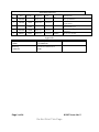
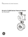
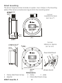
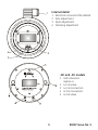
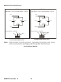
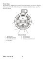
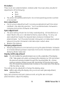
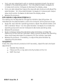
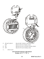
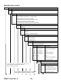
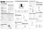
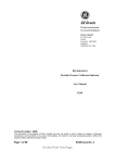
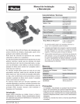
Pressure measurement for research & industry Druck Limited Fir Tree Lane Groby Leicester LE6 0FH England Tel: 0116 231 7100 LP 1000 Series Pressure Sensor User Manual K0267 © Druck Limited 2011 This document is the property of Druck Limited and may not, either in part or whole, be copied or otherwise reproduced, communicated in any way to third parties, nor stored in any data processing system, without the express written authority of Druck Limited. Page 1 of 24 K0267 Issue No. 5 Do Not Print This Page Page 2 of 24 K0267 Issue No. 5 Do Not Print This Page Amendment Record Iss No Date C/N No Originator Typed Workflow No. Amendments New specification 1 16/02/06 - Robert Lee Robert Lee - 2 14/07/05 16834 Robert Lee Robert Lee - 3 27/04/06 18700 18701 Robert Lee Robert Lee - 4 08/08/06 19030 Robert Lee Robert Lee - 5 20/06/11 26584 Robert Lee Robert Lee 166044 Re-format to GE standards –ATEX requirements. Clarification of accuracy statements and materials spec. Red/green on page 1 change to green/red IS version obsolete Approvals Engineering S REES Engineering C GUTTRIDGE Marketing I ABBOTT Technical Communications R LEE Page 3 of 24 K0267 Issue No. 5 Do Not Print This Page Print Instructions Print colour on white, double sided as supplied on disk. Print on paper to 110 gsm, Silverblade matt art, saddle-stitch in 270 gsm covers. Size 120 x 160 mm. Translate into French, German, Italian, Spanish, Portuguese Brazilian, Simplified Chinese and Japanese. THIS PUBLICATION IS PRINTED EXTERNALLY, THIS HARDCOPY IS NOT TO BE USED AS CAMERA COPY. Page 4 of 24 K0267 Issue No. 5 Do Not Print This Page GE Measurement & Control Solutions Druck LP 1000 Series Pressure Sensor User Manual K0267 g © The General Electric Company. All rights reserved Safety To use this equipment safely, use the data and procedures in this publication: • This user manual contains instructions to operate the equipment and maintain it in a safe condition. To prevent damage or injury: • Obey all warnings and cautions. • Use the equipment only for the specified applications. • Operate the equipment only in the specified limits. To install and use the equipment, use only approved engineers who have the necessary skills and qualifications. This product complies with the requirements of the relevant European directives. For data on the applied standards, refer to the “Declaration of Conformity”. Trademarks All product names are trademarks of their respective companies. i K0267 Issue No. 5 Intentionally left blank K0267 Issue No. 5 ii Introduction The Druck LP 1000 series of sensors accurately measures pressures to produce a voltage or current output. Some versions of this sensor contain a front panel LCD showing the current pressure value. The pressure measurement ranges can be between 0 to 0.25 mbar up to 0 to 70 mbar (0 to 0.10 inH2O up to 0 to 1 psi) [vented gauge, one pressure connection or differential two pressure connections]. The measurement cell and electronic circuits are contained in a compact alochromed aluminium enclosure. The LP 1000 series can be mounted using options including a wall mounting bracket, aluminium panel mounting bezel and stainless steel panel mounting bezel. The DC and NC sensors (see Specification) provide in-situ calibration/test facilities, using two non-protruding calibration valves and calibration pressure ports located on the front panel. A calibration key actuates each calibration valve to allow pressure to the calibration pressure ports. On code -L models two LED status indicators locate on the front panel. These indicators can be set to show a high/low pressure state (green/red). The high/ low pressure can be set by a potentiometer. The inverted state for these indicators can be set internally by the manufacturer. 1 K0267 Issue No. 5 Installation CAUTION: 1. INCORRECT ELECTRICAL CONNECTIONS CAN, IN CERTAIN CIRCUMSTANCES, DESTROY THE ELECTRONIC OUTPUT CIRCUIT . 2. BEFORE APPLYING ELECTRICAL POWER, MAKE SURE THE SUPPLY VOLTAGE IS TO THE CORRECT RATING. 3. THIS IS A VERY SENSITIVE SENSOR, ONLY APPLY PRESSURES WITHIN THE PRESSURE RANGE. Note: After switching on, the sensor requires one hour to achieve full accuracy stated in the specification. Positioning The installed position of the sensor should be away from sudden temperature variations, shocks and vibrations and should not be close to strong electromagnetic fields (transformers, motors etc.). The sensor can be mounted in any position with no affect on span, but mounting at an angle may require zero adjustment. Note: At the factory, the sensor is adjusted with the diaphragm in the vertical plane. Possible positioning zero shift can happen, up to a maximum of 0.4 mbar/90° (0.16 inH2O/90°), when changing orientation. Hi Lo groove 10 - 32 UNF M5 x 0.8 K0267 Issue No. 5 2 Wall Mounting Four, 6 mm (0.24”) diameter holes in the mounting plate of the sensor provide securing points. 6mm dia (0.236”) 133 mm (5.24”) 89 mm (3.5”) pressure connections 10/32 UNF female or M5 female 7 mm (0.275”) 6mm dia (0.236”) 7 mm (0.275”) 46 mm (1.8”) 92 mm (3.62”) LP1000-DW/-NW 1 4 2 3 Internal detail 1 3 electrical connector DIN 43650A 2 span adjustment 4 3 zero adjustment damping adjustment K0267 Issue No. 5 Panel mounting The sensor requires a hole to locate in a panel. Four clamps, in the mounting plate of the sensor, provide securing points to the mounting panel. LP1000-DA/-DS Ø114mm (Ø4.2”) 20mm (0.79”) Cut-out 116mm to 121mm (4.6” to 4.7”) 5mm (0.2”) 127mm (5.0”) 61.5mm (2.42”) LP1000-NC/-DC/-DF Ø 128.5 mm (5.0”) Screw terminal Cut-out 130mm to 134mm (5.2” to 5.3”) Ø 4 mm (0.16”) Panel attachment 4 2 3 1 5 Pressure ports 150 mm (5.9”) LP1000 -DA/-DS Dimensions 1 4 Clamp attachment screw adjuster K0267 Issue No. 5 2 5 clamp 3 plate Panel attachment screw 4 Internal detail 1 4 1 2 3 4 Electrical connector DIN 43650A Zero adjustment Span adjustment Damping adjustment 2 3 -NC and -DC models 1 2 3 4 5 5 LED indicators (option L) Lo Cal valve Lo Cal connection Hi Cal connection Hi Cal valve K0267 Issue No. 5 Electrical connections LPX 1000 LPM 1000 DIN 43650A - code C1 and DIN 43650C - code C3 DIN 43650A - code C1 and DIN 43650C - code C3 +VE supply +VE 1 1 N/C 3 E 3 0V/ref GND E GND 2 2 -VE signal Screw terminal - code C2 Screw terminal - code C2 -ve +ve 1 2 N/C 3 +ve GND signal 0V/ref GND 1 G 2 3 G Voltage output (three-wire) Current output (two-wire) Note: GND connects to frame of sensor. Optionally, the frame of the sensor can be connected to earth/ground through the GND terminal. Connection detail K0267 Issue No. 5 6 Adjustments General The NC and DC models can be tested and adjusted in-situ. All other models must be disconnected from the system and, if necessary, removed from the installation to be tested and adjusted. Lo Hi P I/V Hi in Hi Cal Lo in LPM or LPX Cal key Cal key Lo Cal Lo Hi P Hi in I/V LPM or LPX Lo in NC and DC models 1 Calibration key 7 K0267 Issue No. 5 Preparation Before starting, carefully vent pressure from the system. Connect the required test equipment to the calibration ports. Using the calibration keys, open the Hi and Lo valves. 7 1 6 5 3 2 4 Internal detail 1 3 5 7 Lo Cal valve zero potentiometer span potentiometer Hi Cal valve K0267 Issue No. 5 2 4 6 Lo connection Hi connection damping potentiometer 8 Procedure Three multi-turn potentiometers, located under the cover plate, provide for adjustments of the following: Zero Span Damping • The sensor should be positioned in its normal operating position (vertical or horizontal). Zero adjustment • Carry out zero adjustment with no pressure applied and with the sensor installed in the operating position. Turn the potentiometer clockwise to increase and counter clockwise to decrease. Span adjustment • • The span setting should not normally need adjusting. At manufacture a label, fitted to the unit, indicates the factory span setting. To carry out span adjustment apply the required span pressure and adjust the potentiometer. Turn the potentiometer clockwise to increase span output value and counter clockwise to decrease span output value. Release the pressure. Damping adjustment • Damping adjustment is carried out by turning the potentiometer clockwise to increase damping (slower response) and counter clockwise to decrease damping (faster response). Display (LCD) adjustment Note: On LPX models the potentiometers are on the underside of the display PCB. Take great care when unscrewing the retaining nut, this can loosen the pressure sensing module through the mounting pillar (A). A loose pressure sensing module causes the transmitter to become inaccurate. On LPM models one potentiometer locates on the underside of the display PCB, the other on top. This setting can be adjusted to change the display value. Note: Before adjusting the display carry out a zero and span adjustment, detailed above. Apply zero pressure and span pressure and, using the zero and span potentiometers, adjust the display: 9 K0267 Issue No. 5 • • • Carry out zero adjustment with no pressure applied and with the sensor installed in the operating position. Turn the potentiometer clockwise to increase and counter clockwise to decrease the display value. Carry out span adjustment apply the required span pressure and adjust the potentiometer. Turn the potentiometer clockwise to increase span output value and counter clockwise to decrease the display value. Release the pressure. LED indicator adjustment (Option L) This setting can be adjusted to change the indicator operating value. At manufacture the potentiometer is set to the mid-point of the pressure range. • Apply the new indicator operating pressure, adjust the potentiometer until both indicators flicker. Turn the potentiometer clockwise to increase the operating value and counter clockwise to decrease operating value. • Release the pressure. • Apply a pressure below the operating value and slowly increase the pressure until the indicator operates. Apply a pressure above the operating value and slowly decrease the pressure until the indicator operates. • Release the pressure. If necessary, re-adjust the potentiometer by repeating the procedure. Completion Check the output at zero pressure and if necessary, repeat the zero and span adjustments. Release the pressure. Make sure the o-ring seal correctly locates on the rim. Refit the cover. K0267 Issue No. 5 10 3 1 2 A 1 2 3 LPX with option L LPM LPX LPM A - Adjusts LED indicator operating value. Adjusts LCD zero display value. Adjusts LCD zero and span display values. Adjusts LCD span display value. Pillar mount LCD and LED indicator adjustment Models: LP*1***-***D*-1 11 K0267 Issue No. 5 Specif ication Pressure ranges (vented gauge or differential) LP1000 .............................................................. .......0 to 0.25 mbar up to 0 to 2.5 mbar .............................................................. .... 0 to 0.10 inH2O up to 0 to 1.0 inH2O LP1500 .............................................................. .............. 0 to 5 mbar up to 0 to 15 mbar .............................................................. ..0 to 2.01 inH2O up to 0 to 6.03 inH2O LP1800 .............................................................. ........... 0 to 20 mbar up to 0 to 70 mbar .............................................................. 0 to 8.04 inH 2O up to 0 to 28.15 inH2O Line pressure .............................................................. ............................... 2000 mbar (800 inH 2O) Overpressure LP1000 .............................................................. ..................................250 mbar (100 inH2O) LP1500 .............................................................. ..................................700 mbar (280 inH2O) LP1800 .............................................................. ............................... 1200 mbar (480 inH 2O) Pressure media .... ... gases and liquids compatible with alochrome 1000, aluminium alloy (2000 Series), beryllium-copper CB101, brass C268-0, Inconel X750, loctite (510 & 518), Nitrile (Buna-N), PVC, stainless steel, Delrin, polyurethane. Accuracy including non-linearity, hysteresis and repeatability normal ........................ ±0.5% of calibrated range option (code A) ......................±0.25% of calibrated range Long term stability in standard conditions will not change by more than 1% of the calibrated range, averaged over 12 months. Temperature effects ............................................................ .....[over 0°C to +50°C (32°F to +122°F)] ranges up to 1.25 mbar (0.5 inH2O) ................................. ............................. ±0.02 mbar (0.01 inH2O) ranges above 2 mbar (0.8 inH2O) up to 2.5 mbar (1.0 inH2O) .......... ±0.04 mbar (0.02 inH2O) ranges above 5 mbar (2.0 inH2O) up to 7.5 mbar (3.0 inH2O) .......... ±0.12 mbar (0.05 inH2O) ranges above 10 mbar (4.0 inH2O) up to 15 mbar (6.0 inH2O) .......... ±0.25 mbar (0.10 inH2O) ranges above 20 mbar (8.0 inH2O) up to 35 mbar (14.0 inH2O) ..........±0.5 mbar (0.20 inH2O) ranges above 40 mbar (16.0 inH2O) up to 70 mbar (28.15 inH2O).....±1.0 mbar (0.40 inH2O) Operating temperature range ........................................ .................. 0°C to +50°C (32°F to +122°F) Humidity ........................................................................................................... ......0 to 100% RH Environmental protection (except models with C2 connections) ................... .... IP 64 (NEMA 3) Weight .............................................................. ........................0.4 kg to 0.9 kg (1lb to 2lb) Power supply (Vs) (at the terminals) LPX sensor without display............................................................................................... .....10 to 30 V d.c. LPX sensor with display...................................................................................................... .....15 to 30 V d.c. LPX sensor with display and LED indicators............................................................. .....20 to 30 V d.c. LPM sensor ........................................................................................................... .....10 to 30 V d.c. LPM sensor (0 to 10 V d.c. output).................................................................................. .....15 to 30 V d.c. K0267 Issue No. 5 12 Power supply effects................................................................................±0.05% of full-scale/V d.c. Insulation resistance ......................................................................................... 100 Mohms (at 50 Vd.c.) Load impedance LPM 1000 .......................................................................................................................5kohms minimum LPX 1000 ................................................................................................... R <(VPSU - VS (min))/20 kohms Adjustment range Zero ......................................................................................................................±0.3 mbar (0.012 inH2O) Span ....................................................................................................................................±5% of full-scale Damping ................................................................................................... 10 millisecond to 2 seconds (factory set at minimum) Connections Pressure..................... 10/32 UNF female (with 1/8” i/d tube), M5 female or 4mm i/d tube Electrical .................................................................... DIN43650A, DIN43650C or screw terminal Output signal (uni-directional) LPM (3-wire) ...............................................................................................................................0 - 2.5 V d.c. ............................................................................................................................................................ 0 - 5 V d.c. ............................................................................................................................................................ 1 - 6 V d.c. ..........................................................................................................................................................0 - 10 V d.c. LPX (2-wire) .....................................................................................................................................4 - 20 mA Output signal (bi-directional) LPM (3-wire) ...............................................................................................................2.5 V d.c. ±2.5 V d.c. ................................................................................................................................................ 5 V d.c. ±5 V d.c. LPX (2-wire) .....................................................................................................................................12 ±8 mA For advice and service, go to: www.ge-mcs.com 13 K0267 Issue No. 5 Identification codes LP Base Model Number Code Output type X1 mA M1 V d.c. Code Output 0 2.5 mbar (URL) 0.25 mbar to 2.5 mbar (URV) 1.0 inH2O (URL) 0.10 inH2O to 1.0 inH2O (URV) 5 15 mbar (URL) 5 mbar to 15 mbar (URV) 6.03 inH2O (URL) 2.01 inH2O to 6.03 inH2O (URV) 8 70 mbar (URL) 20 mbar to 70 mbar (URV) 28.15 inH2O (URL) 8.04 inH2O to 28.15 inH2O (URV) Code Pressure input 0 Gauge 1 Differential Code 0 1 2 Pressure connection 10-32 UNF female to 1/8” barbed fitting M5 female M5 female to 4mm barbed fitting Code Electrical connection C1 DIN 43650 form A C2 Screw terminals C3 DIN 43650 form C Code Special feature S Standard L Green/red status indicators* Code Display option DA LCD indicator Mounting kit Aluminium bezel DC LCD indicator FPM† & in-situ calibration FPM† DF LCD indicator DS LCD indicator Stainless steel bezel DW LCD indicator Wall mount bracket (blank) None None NC None FPM† & in-situ calibration NW None Wall mount bracket Code Approvals 1 * LPX1xxx-CxLDx-1-x and LPX1xxx-CxLDx-2-x only **Only available with DC & NC models. † FPM = front panel mount Code Options Example identification code LP X1 5 K0267 Issue No. 5 1 2 -C1 None S 14 DC -1 A Accuracy 0.25% full-scale B Non-standard range C 3-point calibration certificate D 5-point calibration certificate E Calibration key (kit of 2) ** -E