Transcript
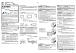
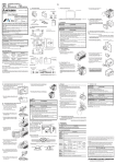
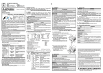
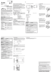
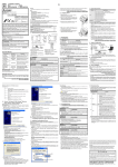
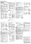
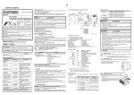
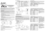
JY997D17101A Side ENGLISH Applicable standard 2. Installation and Remove FX3U-7DM made in May, 2005 or later complies with the EC Directive (EMC Directive). Further information can be found in the following manual. However, FX3UC-32MT-LT does not comply with EC Directive (EMC Directive). → Refer to FX3U Series Hardware Manual (Manual No. JY997D18801) 1. Outline The FX3U-7DM display module (hereinafter called display module) is installed to the FX3U / FX 3UC Series PLC main unit (FX3UC-32MT-LT provided as standard equipment) to display messages (alphabet, numbers, and Japanese characters) or to monitor/ change device states. INSTALLATION PRECAUTIONS Manual Number JY997D17101 1.1 Incorporated Items Revision A Check if the product and accessories shown below are included in the package: Date May 2005 Display module mounting top cover Manual This manual • During transportation avoid any impact as the product is a precision instrument. Check the operation of the product after transportation. 1) Turn off the power. 2) Pushing the top cover hook (right fig. A), remove the top cover (right fig. B), as shown in the right figure. 2 26 25 24 23 22 21 20 17 16 15 10 11 12 13 14 3 2 1 Associated Manuals Manual name Description JY997D15401 Explains external dimensions, installation, and specifications o f F X 3 U - 7 D M- H LD di s pl ay module holder. JY997D16501 MODEL CODE: 09R516 E x plai ns FX 3 U S er ies P LC specification details for I/O, wir ing, installation, and maintenance. 16 Alphabets, Numbers, Japanese character, Shift JIS Level-1, 2 Japanese/English RU N ST OP Use to move cursor or set the value. [4] "+" button Use to move cursor or set the value. [5] "OK" button Use to choose the item, set the value, etc. [7] Top cover fixing hook 0 2 1 10 11 3 12 4 13 5 14 3)’ 6 15 20 7 3.4 Power Supply Specifications 27 26 25 24 23 22 21 17 16 5V DC, 20 mA is supplied from the internal power supply in main unit. 21 3) 20 C D 1 0 7 6 5 4 3 2 12 Use to cancel operation or return to previous screen. 11 Displays current time and monitored status of device. [2] "ESC" button 10 [1] Display General specifications are the same as the PLC main unit. For general specifications, refer to the following manual. → Refer to FX3U Series User's Manual - Hardware Edition 3) When installing Install the display module (right fig. C) to E on the main unit (right fig. D) as indicated with the arrow 3). When removing Remove the dis pl ay module (right fig. C) from the main unit (right fig. D) as indicated with the arrow 3)'. OU T Description [3] "-" button 4 operation buttons (OK, ESC, +, and -) 3.3 General Specifications 66.3(2.62") IN Name 13(0.52") 3U Approx. 8.5(0.34") FX3U Button [6] Connector for main unit Used to connect display module to main unit. Manual No. 15 /ES MR -48 [7] 11.5 [5] (0.46") No. -48M FX3U3U-48M FX Displayed Character letters Language for menu display 3U [4] 48(1.89") 7 6 5 4 3 2 1 14 0 IN 41.8(1.65") . Number of letters 16 letters × 4 lines (2 byte letter: 8 letters × 4 lines) R WE PO 7 6 5 4 Description STN monochrome liquid crystal display/ Backlight: LED (green) FX 35 (1.38") This manual classify the safety precautions into two categories: Item 13 Display module mounting top cover B A [6] [2] [3] [1] may also be Ver. 1.00 and later Display device/ backlight 12 Display module Safety Precaution (Read these precautions before use.) Depending on circumstances, procedures indicated by linked to serious results. In any case, it is important to follow the directions for usage. FX3UC Series PLC* 3.2 Display Specifications 11 Unit: mm (inches) MASS (Weight): Display module 20g (0.05lbs) Display module mounting top cover 10g (0.03lbs) 0 T OU Indicates that incorrect handling may cause hazardous conditions, resulting in medium or slight personal injury or physical damage. Applicability Ver. 2.00 (from the first product) and later * FX3UC-32MT-LT has this display module provided as standard equipment. Installation to and removal from the FX3U Series PLC is shown below. For installing to and removing from the FX3UC Series PLC main unit, refer to FX3UC Series PLC main unit manual. However, FX3UC Series PLC manual is only available in Japanese. 1.2 External Dimensions and Part Names 2005 Mitsubishi Electric Corporation Indicates that incorrect handling may cause hazardous conditions, resulting in death or severe injury. Model FX3U Series PLC FX3U Effective May 2005 Specifications are subject to change without notice. and 3.1 Applicable PLC 10 This manual describes the part names, dimensions, mounting, and specifications of the product. Before use, read this manual and manuals of relevant products fully to acquire proficiency in handling and operating the product. Make sure to learn all the product information, safety information, and precautions. And, store this manual in a safe place so that you can take it out and read it whenever necessary. Always forward it to the end user. Registration The company name and the product name to be described in this manual are the registered trademarks or trademarks of each company. FX3U-7DM display module TRANSPORT AND STORAGE PRECAUTIONS • Use the product in the environment within the general specifications described in PLC main unit manual (Hardware Edition). Never use the product in areas with dust, oily smoke, conductive dusts, corrosive gas (salt air, Cl2, H2S, NH3, SO2, or NO2), flammable gas, vibrations or impacts, or expose it to high temperature, condensation, or wind and rain. If the product is used in such a place described above, electrical shock, fire, malfunction, damage, or deterioration may be caused. • Do not touch the conductive parts of the product directly, thus avoiding failure or malfunction. • Fix the display module securely to the specified connector. Incorrect connection may cause malfunction. PO W ER USER'S MANUAL • Please contact a company certified in the disposal of electronic waste for environmentally safe recycling and disposal of your device. • Cut off all phases of the power source externally before starting the installation or wiring work, thus avoiding electric shock or damages to the product. RU N B FX3U-7DM DISPOSAL PRECAUTIONS INSTALLATION PRECAUTIONS 17 B JAPANESE 16 A 15 Side 14 B 13 Side 4. Function List /ES MR -48 For the function list, refer to the PLC main unit manual. However, FX3UC Series PLC manual is only available in Japanese. → For FX3U Series PLC, refer to FX3U Series User's Manual - Hardware Edition FX RU N STO P Fixes the display module installing top cover on PLC. FX3U-48MR/ES E FX3U-7DM-HLD For the operation of the display module, refer to the PLC main unit manual. FX3U-7DM OU 0 T 1 21 22 23 24 WE RU 0V X0 24V X2 X1 X4 X3 X6 X5 X10 X7 X12 X11 IN X14 X13 X16 X15 X22 X20 X17 X21 S/S X23 L N 0V X0 24V X2 X1 X4 X3 X6 X5 X10 X7 0 1 2 3 4 5 6 7 20 21 22 23 24 IN 10 11 12 13 14 15 16 17 X12 X11 POWE X14 X13 X16 X15 6 7 17 5 FX3UFX3U-48M /ES MR -48 P STO X22 X20 X17 X21 N 2 4 FX N R 20 3 RUN S/S L 27 26 25 PO B 2 16 20 7 6 17 5 16 4 15 3 14 2 13 1 12 0 11 IN 10 15 G 5) 3U Note: FX3UC Series PLC specification details for I/O, wiring, installation, and maintenance can only be found in the Japanese Manual. → Refer to FX3U Series User's Manual - Hardware Edition This manual confers no industrial property rights or any rights of any other kind, nor does it confer any patent licenses. Mitsubishi Electric Corporation cannot be held responsible for any problems involving industrial property rights which may occur as a result of using the contents noted in this manual. F D 14 4) Place the G side of the display module mounting top cover (right fig. F) onto the main unit (right fig. D). 5) The display module mounting top cover (right fig. F) is installed in the Main module (right fig. D) as shown in the right figure. FX3U-7DM 13 Install to control panel → For installation, refer to FX3U-7DM-HLD User's Manual. 12 Install to main unit 11 FX3U Series User’s Manual - Hardware Edition 1.3 Installation Example 10 FX3U-7DM-HLD User’s Manual X 0 1 2 3 4 5 6 7 20 21 22 23 Warranty Mitsubishi will not be held liable for damage caused by factors found not to be the cause of Mitsubishi; machine damage or lost profits caused by faults in the Mitsubishi products; damage, secondary damage, accident compensation caused by special factors unpredictable by Mitsubishi; damages to products other than Mitsubishi products; and to other duties. 10 11 12 13 14 15 16 17 PO RU How to obtain manuals For the necessary product manuals or documents, consult with the Mitsubishi Electric dealer from where you purchase your product. BAT OUT Y0 Y2 COM1 Y1 Y3 R ERRO 0 1 2 3 4 5 6 7 20 21 22 23 24 10 11 12 13 14 15 16 17 FX3U Y4 Y6 COM2 Y5 Y7 Y10 Y12 COM3 Y11 Y13 OUT FX3U Y14 Y16 Y20 Y22 COM4 Y15 Y17 Y21 Y23 Y0 Y2 COM1 Y1 Y3 R Y4 Y6 COM2 Y5 Y7 ER 0 1 2 3 4 5 6 7 20 21 22 23 For safe use 10 11 12 13 14 15 16 17 Y10 Y12 COM3 Y11 Y13 Y14 Y16 Y20 Y22 COM4 Y15 Y17 Y21 Y 3. Specification STARTUP AND MAINTENANCE PRECAUTIONS • Do not disassemble or modify the unit. Doing so may cause failure, malfunction or fire. * For repair, contact your local Mitsubishi Electric distributor. • Do not drop the product or do not exert strong impact, doing so may cause damage. • This product has been manufactured as a general-purpose part for general industries, and has not been designed or manufactured to be incorporated in a device or system used in purposes related to human life. • Before using the product for special purposes such as nuclear power, electric power, aerospace, medicine or passenger movement vehicles, consult with Mitsubishi Electric. • This product has been manufactured under strict quality control. However when installing the product where major accidents or losses could occur if the product fails, install appropriate backup or failsafe functions in the system. HEAD OFFICE : MITSUBISHI DENKI BLDG MARUNOUTI TOKYO 100-8310 HIMEJI WORKS : 840, CHIYODA CHO, HIMEJI, JAPAN