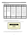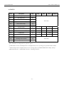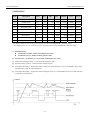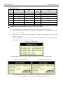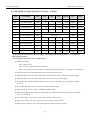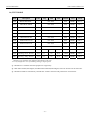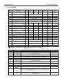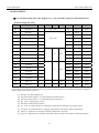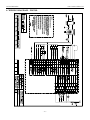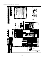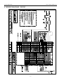
1
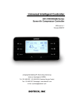
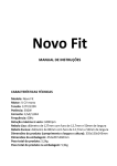
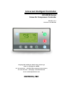
Universal Intelligent Controller
UIC-DX330 Series
Screw Air Compressor Controller
2005-Dec rev. 1
Firmware v2.7b R071116
Joongang-ilbo building 6F, Wonsi-dong, Danwon-gu
Ansan-si, Gyeonggi-do, KOREA
Tel : 031-495-3767 , 031-495-3916 (Customer Service Center)
Fax : 031-495-3917 Homepage : www.dotech21.com
E-mail : [email protected]
DOTECH, INC
UIC-DX330 Series
User’s Manual Rev 2.0
※ Read this direction for safety first..
▣ Direction for safety
This direction is for using the product correctly so that you could be safe from danger or incident.
Please carefully keep this all direction.
z
Please use with being attached to a dual safety device in case of using for controlling instruments which could be
effective to human life or property (eg: controlling atomic energy, medical instruments, cars, trains, flights, burners,
amusement instruments or safety machinery).
z
Please use with panel, there is a possibility getting an electric shock.
z
Do not inspect or test with connecting power.
z
Please connect after checking the terminal number when connecting power.
z
Do not reorganize except mechanic from 『Dotech』.
z
Do not use outdoor. It would be a cause making the product life shorter.
z
When connecting wires, please give a good screw on terminal. There is a possibility causing a fire with bad connection.
z
Please use in the proper performance zone. If you don’t, there is a possibility making the product life shorter or, causing
a fire accident.
z
Do not use a load which is exceeded proper value of opening and shutting capacity of a relay contact. This will cause
bad insulation, bad contact and bad connection.
z
When cleaning, water or liquid including oil are prohibited, only clean with soft and dried cloth.
z
Do not use in the place where there is inflammability gas, explosiveness gas, moisture, a direct ray of light, radiation,
vibration and a shock.
z
Please prevent from getting a dirt or leftover wire inside of this product.
When connecting a sensor, please connect correctly after checking the polarity.
Some of the setting, size etc. on this manual could be changed without an advance notice.
-2-
UIC-DX330 Series
User’s Manual Rev 2.0
.
Warranty Information
This is the warranty below for customer who has a license or product from 『Dotech』.
condition of warranty
The warranty period for 『Dotech』 products is a year so that it is provided support of the product during the warranty
period.
『Dotech』 does not have a responsibility for problems of product under the circumstance below.
In the case of using without concerning the proper form mentioned on the manual.
In the case of problems caused from both external artificial and environmental factors.
Please contact 『Dotech』 in advance if there is any problem of product caused during the warranty period.
If the problem of product is informed from customer in the warranty period, it will be checked up in the customer area or sent to
『Dotech』 to check and conduct repair of exchange services directly. If the product is over the warranty period or that is on the
condition that it is not mentioned on manual, customer would be suggested to pay the cost of repair, exchange and delivery.
On the condition that suggestions for ‘Warranty Condition Performance’ below are not against the law, 『Dotech』 is not
responsible for any compensation and guarantee caused by losses or damages by business interruption, loss, return.
Warranty Condition Performance
Dotech is not responsible for any loss, damages, expenses insisted by customer, delegate, contractor except for customer claims
caused by the condition of warranty above.
The condition of warranty mentioned above is the exclusive customer’s right. Dotech refuses any conditions of warranty for
special purpose except for the condition of warranty.
Warranty Condition Performance does not apply any trouble caused by not following exact direction. It is responsibility for
customer to decide usage or product.
All the conditions of warranty are actually applied and Nobody has authority to modify or extend.
-3-
UIC-DX330 Series
User’s Manual Rev 2.0
Revision Information
Nov. 17, 2007: Revision #1 (F/W Rev 2.7b R071116)
-4-
UIC-DX330 Series
User’s Manual Rev 2.0
Index
1. OUTLINE ................................................................................................................................................................................. 8
1) SPECIAL ADVANTAGES ......................................................................................................................................... 9
1-1) Noise Solution ................................................................................................................................................................. 9
1-2) RISC TYPE MICOM ..................................................................................................................................................... 9
1-3) Black Box : A recorder of operation status ..................................................................................................................... 9
1-4) Display for operation status and/or maintenance information (trip computer).............................................................. 9
1-5) Big Size Graphic LCD (Wide Temperature Range Type : -20 ~ +70℃) ......................................................................... 9
1-6) Minimization ................................................................................................................................................................... 9
1-7) Scalability ....................................................................................................................................................................... 9
2) BASIC SPECIFICATION ........................................................................................................................................ 10
2-1) General Specification ................................................................................................................................................... 10
2-2) CPU & LCD ................................................................................................................................................................. 10
2-3) Digital Input & Output ................................................................................................................................................. 10
2-4) Analogue Input & Output.............................................................................................................................................. 10
2-5) Communication Specification ....................................................................................................................................... 10
2-6) Installation Circumstance ............................................................................................................................................. 10
2. INPUT / OUTPUT SPECIFICATION.................................................................................................................................. 11
1) DIGITAL INPUT SIGNAL ...................................................................................................................................... 11
2) DIGITAL OUTPUT SIGNAL ................................................................................................................................... 12
3) ANALOGUE INPUT SIGNAL .................................................................................................................................. 13
4) ANALOGUE OUTPUT SIGNAL .............................................................................................................................. 14
5) COMMUNICATION SIGNAL .................................................................................................................................. 15
5-1) SYSTEM BUS ................................................................................................................................................................ 15
5-2) LOCAL BUS.................................................................................................................................................................. 15
6) CONTROL POWER INPUT .................................................................................................................................... 16
3. CONSTITUTION ................................................................................................................................................................... 17
1) OPERATION AND DISPLAY PART .......................................................................................................................... 17
1-1) Basic Constitution ......................................................................................................................................................... 17
1-2) Operation Part .............................................................................................................................................................. 17
1-3) Program Setup Part ...................................................................................................................................................... 17
2) MEASUREMENTS AND MOUNT INFORMATION ...................................................................................................... 18
3) DISPLAY FOR OPERATION STATUS ....................................................................................................................... 19
4) OPERATION BUTTON FUNCTION ......................................................................................................................... 19
5) STATUS DISPLAY RAMP ...................................................................................................................................... 20
6) SYMBOL EXPLANATION ...................................................................................................................................... 21
-5-
UIC-DX330 Series
User’s Manual Rev 2.0
6-1) Equipment Status Display ............................................................................................................................................. 21
6-2) Digital Input Signal ...................................................................................................................................................... 22
6-3) Digital Output Signal .................................................................................................................................................... 22
4. MENU CONSTITUTION ...................................................................................................................................................... 23
1) MENU CONSTITUTION TYPE ............................................................................................................................... 23
2) MAIN MENU CONSTITUTION (EXAMPLE)............................................................................................................. 24
3) SUB MENU CONSTITUTION (EXAMPLE) ............................................................................................................... 24
4) MENU CONSTRUCTION ...................................................................................................................................... 25
5) MENU ACCESS LEVEL ........................................................................................................................................ 26
6) STATUS ........................................................................................................................................................... 27
7) OPERATION ................................................................................................................................................... 28
8) SCHEDULE ..................................................................................................................................................... 29
9) RUNNING LOG ............................................................................................................................................... 30
9-1) Trip Message................................................................................................................................................................. 31
9-2) Alarm Message ............................................................................................................................................................. 32
9-3) Start Inhibit Message .................................................................................................................................................... 32
9-4) Running Log Message................................................................................................................................................... 33
9-5) Maintenance Message................................................................................................................................................... 33
10) MAINTENANCE ........................................................................................................................................... 34
11) SHUTDOWN.................................................................................................................................................. 35
12) ALARM MODE ............................................................................................................................................. 35
13) START INHIBIT ............................................................................................................................................ 35
14) COMPRESSOR ............................................................................................................................................. 36
15) VSD MODE (VARIABLE SPEED DRIVE CONTROL) – V MODEL ............................................................................ 37
16) TEST MODE .................................................................................................................................................. 38
17) CONFIGURE ................................................................................................................................................. 39
18) DIAGNISTIC ................................................................................................................................................. 40
19) SYSTEM DATE / TIME .................................................................................................................................. 41
5. HOW TO INSTALL ............................................................................................................................................................... 42
6. WIRING DIAGRAM – DX330L ........................................................................................................................................... 43
7. WIRING DIAGRAM – DX330M .......................................................................................................................................... 44
8. WIRING DIAGRAM – DX330V........................................................................................................................................... 45
-6-
UIC-DX330 Series
User’s Manual Rev 2.0
※ Please check the product to the model ordering before usage.
Model
Suffix Code
DX330
Type
Description
UIC for Screw Air-Compressor
-
L
Basic Model
-
M
Multi-Function Model
-
V
VSD Model
-
Language
Korean
-
E
English
-
C
Chinese
-
A
Customer Language
※ Related Product Information.
Exclusive Temp. Sensor (DPR-TH02-06D100L) : Delivery Temp., Oil Reclaimer Temp.
Exclusive Temp. Sensor (DPR-TH1-ET) : Ambient Temp. Sensor
Pressure Sensor (DP500 Series) : Delivery Pressure, Oil Reclaimer Pressure
DX330 Exclusive Transformer : AC220V / AC24V
DX380 : Equipment Number Control Unit – Max. 8 units
DA-32 : Equipment Number Control System (Touch Screen Type), Max. 32 units
DA-100 : DX330 Monitoring & Trend System (Free of Charge)
※ Related Product Information
DX330 MODBUS RTU PROTOCOL MANUAL (PDF)
Pressure Sensor Data (PDF)
Temp. Sensor Data (PDF)
Wiring Diagram (PDF,DWG)
-7-
UIC-DX330 Series
User’s Manual Rev 2.0
1. OUTLINE
UIC-DX330 is based on Micro Processor and the most advanced equipment for controlling electricity conducting efficient
operation of a screw air compressor. UIC-DX330 is a system managing the compressor’s operation intensively, saving energy
through controlling of timing for capacity adjustment, preventing problems in advance with alarming system and informing the
required preventative and maintenance schedule. In the other word, UIC-DX330 conducts the best operation (control)
according to the condition set up and operating circumstance.
Additionally, UIC-DX330 has VSD and PID function together as an option, so it is possible to reduce more than maximum
30% of energy cost.
▣ High reliability RISC MICOM
▣ Big size graphic LCD which is available for Korean/English/Chinese/Japanese
▣ Max 160 events of running log storable (Non-volatile) – Easy preventative & maintenance and analysis for trouble
▣ Automatic calculation and notice function for preventative & maintenance, consumable parts exchange information and
expected schedule
▣ Automation of economical operation by embedded weekly timer
▣ Various analogue outputs. (Inverter speed control, dispatch pressure transmission, delivery temperature transmission)
Unload pressure : Pressure value under unload operation with closing intake valve on compressor
Load pressure : Pressure value under load operation with opening intake valve on compressor
Load delay : Delay time when compressor starts load operation from starting
Re-load delay : Minimum delay time when compressor start load operation from unload operation
Auto stop delay
: Compressor is stopped in case of continuous operation at unload operation during auto stop delay
time.
Manual stop delay : Compressor is stopped after unload operation during manual stop delay time.
-8-
UIC-DX330 Series
User’s Manual Rev 2.0
1) Special Advantages
UIC-DX330 is a stable electronic control unit for screw air compressor which can provide users with multi-language
(currently Korean, English, Chinese and Japanese) display and running log for integral control and management of the
equipments. It adopts the method of digital process by high efficiency RISC type microprocessor and occupies enough
installation space and stability by unifying display module and control module. It provides convenience to let users know a
status of operation at once through display.
1-1) Noise Solution
It is inevitable to figure for noise as an industrial controller. The digital input and output signal of UIC-DX330 is
isolated, so it can not be allowed to flow external signal into the main board inside. Also, CPU on main board mounts
HARDWARE WATCHDOG TIMER which can automatically recover from CPU down occurred by noise per 32msec,
and BROWN-OUT function embedded in CPU inside supervises control power in real-time.
1-2) RISC TYPE MICOM
An assembler instruction in CPU can perform 7.3728Mbps, and logic for controlling written in CPU inside needs about
1 msec based on 1 cycle. In this regard, sampling rate is about 10 times faster than the existing controllers, so it has less
probability of malfunction and more precise control.
1-3) Black Box : A recorder of operation status
It is possible for UIC-DX330 to store maximum until 160 events of running log, so it is easy for preventative &
maintenance and trouble-shooting. Additionally, it is possible to verify the operation data at site when trip occurs, so it is
helpful for users to know the reason of trouble and the status of equipment in real-time.
1-4) Display for operation status and/or maintenance information (trip computer)
UIC-DX330 has the display function for operation status, delay time and ready time by counting reversely, so users can
recognize the status of compressor at a glance. Also, it has the basic function to notify parts and oil checking and
exchanging schedule by calculating it automatically according to the information of operation.
1-5) Big Size Graphic LCD (Wide Temperature Range Type : -20 ~ +70℃)
Display part of UIC-DX330 adopts big size graphic LCD for user’s easy operation and recognition. (Currently
applicable for Korean, English, Chinese and Japanese)
1-6) Minimization
It is possible to minimize compressor by occupying a small space due to unifying design of control part and display part.
1-7) Scalability
It provides users with RS485 port, MODBUS RTU standard protocol and MMI software and automatic interface.
-9-
UIC-DX330 Series
User’s Manual Rev 2.0
2) Basic Specification
2-1) General Specification
Input Power
AC24V 50/60Hz, DC24V
Power Consumption
Max. 20VA
CPU
AT mega 128, 16MHz
LCD
240 X 128 pixel, LED Backlight
Input Type
Opto-Isolation
Number of Input
10Points (5 X 2 Common)
Signal Power
AC24V or DC24V
Output Type
Relay Contact
Number of Output
12Points (4 X 3 Common)
Relay Contact Type
250V, 10A
Temp. Sensor
NTC 3 Points
4~20mAdc
2 Points (Internal Sensor Power 24V)
Correction of Deviation
Software
Number of Channel
3 Channels
Output Type
4~20mA
Setup Type
Software
Type
RS485(Half-Duplex), 1 Channel (Modbus RTU)
Power Conditions
2-2) CPU & LCD
CPU, LCD
2-3) Digital Input & Output
Digital Input
Digital Output
2-4) Analogue Input & Output
Analog Input
Analog Output
2-5) Communication Specification
4800, 9600, 19200, 38400 BPS (default 9600)
Speed
Parity None, Data 8bit, Stop 1bit
Communication
Distance
Max. 1.2Km
Recommended Cable
BELDEN 9842 or 8761
Place
Indoor
Installation
Operation Temp.
-10 ~ 60 ℃
Circumstance
Storage Temp.
-30 ~ 80 ℃
Operation Humidity
5~95% (No condensation)
2-6) Installation Circumstance
- 10 -
UIC-DX330 Series
User’s Manual Rev 2.0
2. Input / Output Specification
1) Digital Input Signal
Pin
Name
Function
J13.1
ID1
Emergency Stop S/W Signal
Fault (open)
J13.2
ID2
Overload Fan Motor Signal
Fault (open)
J13.3
ID3
Overload Main Motor Signal
Fault (open)
J13.4
ID4
Reverse Phase Unit Signal
Fault (open)
J13.5
ID5
Reserved Input Signal
J13.6
IDC1
Input Common Terminal 1
Pin
Name
J14.1
ID6
Oil-Filter High DP Alarm Signal
Alarm (closed)
J14.2
ID7
Air-Filter High DP Alarm Signal
Alarm (closed)
J14.3
ID8
Oil Reclaimer DP Alarm Signal
Alarm (closed)
J14.4
ID9
Remote Load/Unload Control
Remote (closed)
J14.5
ID10
Remote Start/Stop Control
Run (closed)
J14.6
IDC2
Input Common Terminal 2
Function
- 11 -
Active state
Active state
UIC-DX330 Series
User’s Manual Rev 2.0
2) Digital Output Signal
Pin
Name
Function
J21.1
N1
-
J21.2
N2
-
J21.3
N3
-
J21.4
N4
Load Solenoid Control
J21.5
C1
Output Common Terminal 1
Pin
Name
J22.1
N5
Main Magnetic Contactor
ON
J22.2
N6
Star Magnetic Contactor
ON
J22.3
N7
Delta Magnetic Contactor
ON
J22.4
N8
-
J22.5
C2
Output Common Terminal 2
Pin
Name
J23.1
N9
Multi Function Port N9
J23.2
N10
Multi Function Port N10
J23.3
N11
Multi Function Port N11
J23.4
N12
Multi Function Port N12
J23.5
C3
Output Common Terminal 3
Function
Function
※ N9~N12 Functions are applicable from “M” models.
- 12 -
Active state
ON
Active state
Active state
UIC-DX330 Series
User’s Manual Rev 2.0
3) Analogue Input Signal
Î
Î
Pin
Name
Function
Type
Range
J11.1
+VDC
Sensor Power (+V Common)
J11.2
B4
Delivery Press. Sensor Input
4~20mA
Settable
J11.3
B5
Oil Reclaimer Press. Sensor Input
4~20mA
Settable
J11.4
GND
0V Common (Earthing of Shield Wire)
Type
Range
NTC 10K
-30 ~ 200 ℃
NTC 5K
-30 ~ 200 ℃
NTC 10K
-30 ~ 200 ℃
Oil reclaimer sensor input is applicable from “M” models.
Pin
Name
Function
J12.1
B1
Delivery Temp. Sensor Input
J12.2
GND
0V Common
J12.3
B2
Ambient Temp. Sensor Input
J12.4
GND
0V Common
J12.5
B3
Oil Reclaimer Temp. Sensor Input
Oil reclaimer temp. sensor input and ambient temp. sensor input are applicable from “M” model.
- 13 -
UIC-DX330 Series
User’s Manual Rev 2.0
4) Analogue Output Signal
Pin
Name
J6.1
Y1
Inverter Speed Output Signal (in case of VSD Control)
4 ~ 20mA
J6.2
YG1
Inverter Speed Control Output Common
(0 ~ 100%)
J6.3
Y2
Delivery Press. Transmission Signal
4 ~ 20mA
J6.4
YG2
Delivery Press. Transmission Signal Common
※ (Range Setup)
J6.5
Y3
Delivery Temp. Transmission Signal
4 ~ 20mA
J6.6
YG3
Delivery Temp. Transmission Signal Common
(-10 ~ 150℃)
Î
Function
Type
Analogue output signal is application from “V” model.
※ Discharge air press. transmission signal outputs retransmission signal (4~20mA) as the input range of
[configuration, discharge press. low, discharge press. high].
- 14 -
UIC-DX330 Series
User’s Manual Rev 2.0
5) Communication Signal
5-1) SYSTEM BUS
Pin
Name
Function
TB1.1
SG
-
TB1.2
B
SYSTEM BUS TRX-
TB1.3
A
SYSTEM BUS TRX+
Type
RS-485
5-2) LOCAL BUS
Pin
Name
Function
TB2.1
SG
-
TB2.2
B
LOCAL BUS TRX-
TB2.3
A
LOCAL BUS TRX+
Type
RS-485
※ Communication Signal (System Bus, Local Bus Common)
① Communication Type : RS-485
② Communication Speed : 4800, 9600, 19200, 384000 BPS, N, 8, 1, default 9600bps
③ Communication Protocol : MODBUS RTU MODE
④ Recommended Communication Cable : BELDEN 9842 or 8761
BELDEN 9842 Paired- Low Capacitance EIA RS-485
⊙ Number of Pairs: 2
⊙ Total Number of Conductors: 4
⊙ AWG: 24
⊙ Stranding: 7x32
(9842)
⊙ Conductor Material: TC - Tinned Copper
⊙ Insulation Material: PE - Polyethylene
⊙ Outer Shield Material Trade Name: Beldfoil®
⊙ Outer Shield Material: Aluminum Foil-Polyester Tape/TC –
⊙ Tinned Copper
⊙ Outer Jacket Material: PVC - Polyvinyl Chloride
⊙ Plenum (Y/N): N ⊙Plenum Number: 82842
(8761)
⊙ Applications: Computer Cables, Low Capacitance EIA RS-485
※ BELDEN 9842 standard cable is recommendable.
- 15 -
UIC
C-DX330 Serries
User’s Manual
M
Rev 2.0
6) Coontrol Poweer Input
Pin
N
Name
Function
n
J1.1
FG
FIELD GROUND (C
CASE SHIELD
D)
J1.2
G0
A
AC24V(-)
or DC24V(-)
D
J1.3
G
A
AC24V(+)
or DC24V(+)
D
(Power Input
I
Wiring Diagram)
D
- 16 -
Type
UIC-DX330 Series
User’s Manual Rev 2.0
3. Constitution
1) Operation and Display Part
1-1) Basic Constitution
Display Part Specification : 240 X 128 Graphic LCD (LED BACKLIGHT), LED Green 1EA, Red 1EA
Keyboard : Membrane Keypad Switch (8EA)
1-2) Operation Part
Start Switch : Start
Stop Switch : Stop
Reset : Reset when trip occurred
Green Ramp 1 : Ramp showing status of operation
Red Ramp 2 : Ramp showing trip or warning
1-3) Program Setup Part
Select Switch : Selection of setup program or value
Downward Switch : Moving down to setup program or value
Upward Switch : Moving up to setup program or value
Menu Switch : Opening menu for setup
Reset Switch : Returning to the previous menu or initial screen]
- 17 -
UIC-DX330 Series
User’s Manual Rev 2.0
2) Measurements and Mount Information
- 18 -
UIC-DX330 Series
User’s Manual Rev 2.0
3) Display for Operation Status
If you push “ENTER”, it is displayed operation time, loading time, ratio of loading/unloading duty, ambient temp.,
oil reclaimer temp, oil reclamier press. Inverter output and frequency respectively.
4) Operation Button Function
Start / Stop
Select Start / Stop
The equipment starts when pushing start button (Green).
The equipment stops when pushing stop button (Red).
Reset
Reset when trip
The trip reset automatically doesn’t need to push reset button.
Menu
It returns to setup and status menu when pushing menu button
Enter
Choice and storage
Up / Down
Upward (Increase) and/or Downward (Decrease)
Cancel
Return to the previous menu or initial screen
- 19 -
UIC-DX330 Series
User’s Manual Rev 2.0
5) Status Display Ramp
ON / OFF according to operation status
Operation Status
Green
ON / OFF according to alarm status
Alarm Status
Red
ON : LED is always on.
Low speed flickering : On for 0.5 sec./ Off for 0.5 sec.
High speed flickering : On for 0.1 sec./ Off for 0.1 sec.
Spot flickering : On for 0.1 sec. / Off for 4 sec.
OFF : LED is always off.
No.
Status
Operation Status Ramp
00
Initialization
OFF
01
Operation Inhibit
OFF
02
Operation Ready
OFF
Alarm Status Ramp
Spot Flickering
03
Start Delay
(Blowdown check)
Load Operation Request Status : High
Speed Flickering
04
Start Ready
Spot Flickering
Spot Flickering
06
During Operation
(Y/D transfer delay)
Load Operation Request Status : High
Speed Flickering
Normal : OFF
Trip : High Speed
Flickering
Alarm : Low Speed
Flickering
Spot Flickering
07
Load Operation Delay
Load Operation Request Status : High
Speed Flickering
08
Load Operation
ON
Spot Flickering
09
Reload Delay
Load Operation Request Status : High
Speed Flickering
10
Auto-stop Delay
Spot Flickering
11
Manual-stop Delay
Low Speed Flickering
99
Shut-down
OFF
- 20 -
Maintenance : Spot
Flickering
Start Inhibit : Spot
Flickering
UIC-DX330 Series
User’s Manual Rev 2.0
6) Symbol Explanation
6-1) Equipment Status Display
Start / Stop Mode Status Display
LOC : Start /Stop using start / stop key on the equipment
NET : Start / Stop from PC or remote device using protocol
REM : Start / Stop remotely using digital input port on the equipment
SCH : Start / Stop according to setup schedule of [Schedule] menu
Load Operation Mode Display
LOC : Load / Unload operation by press. value of sensor on the equipment
NET : Load / Unload operation from PC or remote device using protocol
REM : Load / Unload operation remotely using digital input port on the equipment
Stop Status Display
Display during equipment’s stop
LOC STOP : Stop by stop button on the equipment
REM STOP : Stop by digital input
NET STOP : Stop by communication function
SCH STOP : Stop by setup time on [Schedule] menu
S.D STOP : Stop when trip occurred
Operation Status Display
Display during equipment’s operation
LOC RUN : Operate by start button on the equipment
REM RUN : Operate by digital input
NET RUN : Operate by communication function
SCH RUN :Operate by setup time on [Schedule] menu
Equipment Status Display
GOOD : Normal status
MAINTEN : Required maintenance
ALARM : Alarm status
S-DOWN : Sensing fault
INHIBIT : Start inhibit
System Lock Signal
- 21 -
UIC-DX330 Series
User’s Manual Rev 2.0
6-2) Digital Input Signal
Symbol
Description
Symbol
Description
Emergency Stop S/W Fault Signal
Oil-Filter High DP Alarm Signal
Overload Fan Motor Fault Signal
Air-Filter High DP Alarm Signal
Overload Main Motor Fault Signal
Oil Reclaimer DP Alarm Signal
Reverse Phase Unit Fault Signal
Remote Load/Unload Control
Spare Input Port
Remote Start/Stop Control
6-3) Digital Output Signal
Symbol
Description
Symbol
Description
Main Magnetic Contactor
Multi Function Port N9
Star Magnetic Contactor
Multi Function Port N10
Delta Magnetic Contactor
Multi Function Port N11
Load Solenoid Control
Multi Function Port N12
- 22 -
UIC-DX330 Series
User’s Manual Rev 2.0
4. Menu Constitution
1) Menu Constitution Type
Main Manu
Sub Menu
Parameter
- 23 -
UIC-DX330 Series
User’s Manual Rev 2.0
2) Main Menu Constitution (Example)
※ Showing menu might be slightly different from “V” model.
3) Sub Menu Constitution (Example)
- 24 -
4) Menu Construction
(Based on ‘M’ model)
* mark is applicable for ‘ V ’ model only.
STATUS
OPERATION
00: Discharge Temp.
01: Discharge Press.
02: Ambient Temp.*
03: Oil Reclaimer Press.
04: Oil Reclaimer Temp.*
05: Differential Press.
06: Total Run Hours
07: Motor Run Hours
08: Motor On/Off Times
09: Loaded Hours
10: Loaded On/Off Times
11: Inverter Control*
12: Discharge Press .
Retrans. *
13: Discharge Temp.
Retrans.*
00: Unload Pressure
01: Load Pressure
02: Auto-Stop Delay Time
03: Stop Delay Time
04: Blowdown Delay
Time
05: Drain Time [On]
06: Drain Interval [Off]
07:Cooling Fan Run
Temp*
08: Cooling Fan Stop
Temp*
00: Discharge Temp Low
01: Oil Reclaimer Press
High
00: Sun : Start ~ Stop
01: Mon : Start ~ Stop
02: Tue : Start ~ Stop
03: Wed : Start ~ Stop
04: Thu : Start ~ Stop
05: Fri : Start ~ Stop
06: Sat : Start ~ Stop
RUNNING LOG.
00:Event #1
01:Event #2
02:Event #3
|
03:Event #160
MAINTENANCE
SHUTDOWN
ALARM MODE
00: Dust Filter Cleaning
01: Suction Filter Change
02: Oil Filter Change
03: Lub. Oil Change
04: Cooler Cleaning
05: Overhaul
00: Discharge Temp High
01: Discharge Press High
02: Oil Reclaimer Temp
High*
03: Oil Reclaimer Press
High*
04: Diff-Pressure High
00: Discharge Temp High
01: Discharge Press High
02: Oil Reclaimer Temp
High*
03: Oil Reclaimer Press
High
04: Diff- Pressure High
05: Ambient Temp High*
CONFIGURE
DIAGNOSTIC
09: LCD Backlight Mode
VSD MODE*
COMPRESSOR
START INHIBIT
SCHEDULE
00: Y-DELTA Transfer
Time
01: Load Delay Time
02: Reload Delay Time
03: Diff. Press Detect
Delay
04: Load Command Mode
05: Starting Command
Mode
06: Power Return Restart
07: Network ID
08: Network BPS
00: VSD Control Mode
01: Maximum Speed
02: Minimum Speed
03: Optimum Speed
04: Unloaded Speed
05: Speed Command(Hz)
06: Speed Command(mA)
07: Proportional Band(P)
08: Integral Time (I)
09: Dead Band
10: Jerk Control Ratio
11: Max. Inverter RPM
12: Max. Inverter Frequency
TEST MODE
00: Manual Test Mode
01: Main Motor MAIN
02: Main Motor STAR
03: Main Motor DELTA
04: Load SOL. Valve
05: Multi Function N9
06: Multi Function N10
07: Multi Function N11
08: Multi Function N12
09: Inverter Control*
10: Discharge Press
Retrans.*
11: Discharge Temp
Retrans*
00: Master Password
Setup
01: Trip/Alarm History
Delete
02: Operation History
Delete
03: Ambient Temp Sensor
Use
04: Oil Press. Use
05: Oil Temp. Use
06: Discharge Press
Correct
07: Oil Press. Correction
08: Ambient Temp.
Correction*
09: Discharge Temp.
Correct
10: Oil Temp. Correction*
11: Discharge Press Min
12: Discharge Press Max
13: Min. Oil Press.
14: Max. Oil Press.
15: Multi Function N9
16: Multi Function N10
17: Multi Function N11
18: Multi Function N12
00: SELF TEST
01: B1 Input
02: B2 Input
03: B3 Input
04: B4 Input
05: B5 Input
06: B4 4mA
07: B4 20mA
08: B5 4mA
09: B5 20mA
10: Y1 4mA*
11: Y1 20mA*
12: Y2 4mA*
13: Y2 20mA*
14: Y3 4mA*
15: Y3 20mA*
16: ADC F/T
17: DAC F/T
UIC-DX330 Series
User’s Manual Rev 2.0
5) Menu Access Level
Access
USER
SERVICE1
SERVICE2
SERVICE3
Level
(CODE = 0009)
(CODE = 0100)
(CODE = 0119)
(CODE = ****)
1.STATUS
1.STATUS
1.STATUS
1.STATUS
2.OPERATION
2.OPERATION
2.OPERATION
2.OPERATION
3.RUNNING LOG
3.RUNNING LOG
3.SCHEDULE
3.SCHEDULE
4.MAINTENANCE
4.MAINTENANCE
4.RUNNING LOG
4.RUNNING LOG
5.SHUTDOWN
5.SHUTDOWN
5.MAINTENANCE
5.MAINTENANCE
6.ALARM MODE
6.ALARM MODE
6.SHUTDOWN
6.SHUTDOWN
7.START INHIBIT
7.START INHIBIT
7.ALARM MODE
7.ALARM MODE
8.COMPRESSOR
8.START INHIBIT
8.START INHIBIT
9.VSD MODE*
9.COMPRESSOR
9.COMPRESSOR
10.TEST MODE
10.VSD MODE*
10.VSD MODE*
11.CONFIGURE
11.TEST MODE
11.TEST MODE
12.CONFIGURE
12.CONFIGURE
13.DIAGNOSTIC
13.DIAGNOSTIC
30 min.
1 hr.
Accessible
Menu
Lasting
Time
1 min.
10 min.
When changing Access Level Mode, make locked by putting [Cancel] button for 3 seconds.
① If putting [Menu] on operating display, it shows access code input display below.
(If putting [Menu] during supporting time, it does not ask Access Code.)
② After input Access Code by [Upward]/[Downward] key, put [Enter] and then, convert to Menu display.
<Display of Access Code Input>
③ If Access Level is under [Service] level 1, [Set expanded operation] parameter does not change.
④ When changing lock mode before lasting time, please push [Cancel] button for 3 seconds.
-26-
UIC-DX330 Series
User’s Manual Rev 2.0
6) STATUS
Item
Description
Units
000
Discharge Temp.
℃
001
Discharge Press.
Bar
002
Ambient Temp.***
Oil Reclaimer Press.
004
Oil Reclaimer Temp.**
℃
005
Differential Press.**
Bar
Total Run Hours
007
008
Min
℃
**
003
006
Step
*
Max
View Only
Bar
H
1
0
99999
Motor Run Hours*
H
1
0
99999
Motor On/Off Times*
T
1
0
99999
*
Default
009
Loaded Hours
H
1
0
99999
010
Loaded On/Off Times*
T
1
0
99999
011
Inverter Control
mA
012
Discharge Press. Retrans.
mA
013
Discharge Temp. Retrans.
mA
View Only
Times and Hours are automatically initialized and counted from “0” in case of over “99999”.
*
*
Times and Hours are changeable over [Service 2]level.
**
Oil Reclaimer Pressure and Temperature are displayed only in case of setting [Use]of related item on Menu.
***
**
Ambient Temperature is displayed only in case of setting [On] on [CONFIGURE:Ambient Temp. Sensor].
Differential Pressure = Oil Reclaimer Pressure – Discharge Pressure
- 27 -
UIC-DX330 Series
User’s Manual Rev 2.0
7) OPERATION
Item
Description
Units
100
Unload Pressure
bar
0.1
4.0
70.0
101
Load Pressure
bar
0.1
3.8
102
Auto-Stop Delay Time
S
1
103
Stop Delay Time
S
104
Blowdown Delay Time
**
Step
Min
Max
Default
View
Access
8.6 bar
USER1
SVC1
65.0
6.5 bar
USER1
SVC1
1
3600
300 S
USER1
SVC1
1
1
60
30 S
USER1
SVC1
S
1
1
600
10 S
USER1
SVC1
105
Drain Time [On]
S
1
1
30
5S
USER1
SVC1
106
Drain Inteval**
S
1
1
3600
60 S
USER1
SVC1
107
Cooling Fan Run Temp***
℃
1
0
200
80 ℃
USER1
SVC1
108
***
℃
1
0
200
70 ℃
USER1
SVC1
Cooling Fan Stop Temp
**
It is displayed only in case of setting [Use]of drain function on [CONFIGURE : Multi Function].
***
It is displayed only in case of setting [Use]of cooling fan function on [CONFIGURE : Multi Function].
① Unload Pressure :
z
It cannot be set under +0.2bar of loaded pressure value.
z
It cannot be set over -0.2bar of alarm pressure value.
② Load Pressure : It cannot be set over -0.2 bar of unload pressure value.
③ Temperature Sensing Capacity : Control(0.01℃), Display(0.1℃)
④ Pressure Sensing Capacity : Control(0.01bar), Display(0.1bar)
⑤ Cooling Fan Run Temp. : Temperature when cooling fan is under operation. (It is recommended to be set more
than 2℃ than cooling fan stop temperature)
⑥ Cooling Fan Stop Temp. : Temperature when cooling fan stops. (It is recommended to be set less than 2℃ than
cooling fan run temperature.)
- 28 -
UIC-DX330 Series
User’s Manual Rev 2.0
8) SCHEDULE
Item
Description
RUN ~ STOP
400
SUN
00 : 00 ~ 00 : 00
401
MON
08 : 30 ~ 18 : 30
402
TUE
08 : 30 ~ 18 : 30
403
WED
08 : 30 ~ 18 : 30
404
THU
08 : 30 ~ 18 : 30
405
FRI
08 : 30 ~ 18 : 30
406
SAT
08 : 30 ~ 12 : 30
※ It is applied and displayed only in case of setting of [Schedule Operation] on [Extend Operation] menu.
※ It is applicable over ‘M’ model.
① It is used in case of start and stop at indicated time.
② The equipment is automatically operated at run time and stopped at stop time.
③ In case of no operation on specific day, run time and stop time are set the same.
④ If run time is after stop time, the equipment shall not be operated.
⑤ It is possible to run & stop by pushing [Run] and [Stop] button during schedule operation. (See the following
picture)
⑥ The equipment shall not be operated after stop time, although pushing [Run] button. (See the following picture).
- 29 -
UIC-DX330 Series
User’s Manual Rev 2.0
9) RUNNING LOG
Occur /
Item
Date
Time
1
YY/MM/DD
H
H
:
M
M
(
X
)
Event #1
2
YY/MM/DD
H
H
:
M
M
(
X
)
Event #2
3
YY/MM/DD
H
H
:
M
M
(
X
)
Event #3
4
YY/MM/DD
H
H
:
M
M
(
X
)
Event #4
5
YY/MM/DD
H
H
:
M
M
(
X
)
Event #5
|
|
160
YY/MM/DD
|
H
H
:
Event
Reset
|
M
M
(
X
|
)
Event #160
※ It is impossible to modify and/or delete the contents of event at the option.
①
When trip alarm occurs (resets), date and history of event are stored at non volatile memory.
②
The maximum number of storable event is 160EA and it is deleted the earliest event and stored the lastest
one in case of over 160EA.
③
When trip alarm is occurred, [Date, Time and Event] is recorded. Also, when trip alarm is reset, “X” mark is
showed next to [Time].
④
When pushing [Enter] button, you can see operation status code, discharge pressure, discharge temperature
and ambient temperature when trip alarm occurs.
(Screen for Trip Alarm Status)
If pushing [MENU] button, you can see the latest alarm history on screen for [Trip Alarm Status].
Discharge Air Status + Whole Status
Oil Reclaimer Status + Whole Status
If pushing [MENU] button, you can see the status of discharge air and oil reclaimer in shifts.
(In case of installation of sensor for oil reclamier pressure or temperature)
- 30 -
UIC-DX330 Series
User’s Manual Rev 2.0
9-1) Trip Message
Item
Description
1
System Fault
2
Emergency Stop
3
4
5
Detect condition
In case of unexpected change of the value of parameter
Sensing
[Digital Signal Input : Emergency Stop] : ON
Reset
[Digital Signal Input : Emergency Stop] : OFF
Sensing
[Digital Signal Input : Fan Motor O.L] : ON
Reset
[Digital Signal Input : Fan Motor O.L] : OFF
Sensing
[Digital Signal Input : Main Motor O.L : ON
Reset
[Digital Signal Input : Main Motor O.L : OFF
Sensing
[Digital Signal Input : Reverse Phase] : ON
Reset
[Digital Signal Input : Reverse Phase] : OFF
Sensing
Discharge Press.
Reset
Discharge Press. < [Alarm Mode : Discharge Press. High] - 0.5bar
Sensing
Discharge Temp.
Reset
Discharge Temp. < [Alarm Mode : Discharge Temp. High] - 5℃
Sensing
Oil Reclaimer Press.
[Alarm Mode : Oil Reclaimer Press. High]
Reset
Oil Reclaimer Press. <
[Alarm Mode : Oil Reclaimer Press. High] – 0.5bar
Sensing
Oil Reclaimer Temp.
[Alarm Mode : Oil Reclaimer Temp. High]
Reset
Oil Reclaimer Temp. <
[Alarm Mode : Oil Reclaimer Temp. High] - 5℃
Sensing
(Oil Reclaimer Press.–Discharge Press.)
Fan Motor O.L.
Main Motor O.L
Reverse Phase
Discharge Press.
[Alarm Mode : Discharge Press. High]
6
High
Discharge Temp.
[Alarm Mode : Discharge Temp. High]
7
High
Oil Reclaimer
8
Press. High
Oil Reclaimer
9
Temp. High
10
Diff. Press. High
Discharge Air Temp. > 50℃
Reset
Browdown Time
[Alarm Mode:Diff. Press. High] &
(Oil Reclaimer Press.–Discharge Press.) < [Alarm Mode:Diff.Press.High] - 0.1bar
Oil Reclaimer Press. > [Start Inhibit : Oil Reclaimer Press. High] in case of exceeding of
11
Over
[Operation : Blowdown Delay Time] during browdown check sequenc.
Discharge
Sensing
In case of occurrence of error on discharge press. sensor (disconnection / short)
P-Sensor
Reset
In case of normal condition of discharge press. sensor
Discharge
Sensing
In case of occurrence of error on discharge temp. sensor (disconnection / short)
T-Sensor
Reset
In case of normal condition of discharge temp. sensor
Sensing
In case of occurrence of error on oil reclaimer press. sensor (disconnection / short)
Reset
In case of normal condition of oil reclaimer press. sensor
Sensing
In case of occurrence of error on oil reclaimer temp. sensor (disconnection / short)
Reset
In case of normal condition of oil reclaimer temp. sensor
Sensing
In case of occurrence of error on ambient temp. sensor (disconnection / short)
Reset
In case of normal condition of ambient temp. sensor
12
13
14
15
16
Oil P-Sensor Fault
Oil T-Sensor Fault
Ambient T-Sensor
※ Fault message occurred is reset by pushing [Reset] button after solving related reason.
- 31 -
UIC-DX330 Series
User’s Manual Rev 2.0
9-2) Alarm Message
Item
Description
Oil Filter
Detect condition
Sensing
[Digital Signal Input : Oil Filter Diff. Press] : ON
Reset
[Digital Signal Input : Oil Filter Diff. Press] : OFF
Sensing
[Digital Signal Input : Air Filter Diff. Press] : ON
Reset
[Digital Signal Input : Air Filter Diff. Press] : OFF
Sensing
[Digital Signal Input : Oil Reclaimer Diff. Press] : ON
Reset
[Digital Signal Input : Oil Reclaimer Diff. Press] : OFF
Sensing
Discharge Press
Reset
Discharge Press < [Alarm Mode : Discharge Press. High]-0.5bar
Sensing
Discharge Temp.
Reset
Discharge Temp. < [Alarm Mode : Discharge Temp. High]-5℃
Sensing
Oil Reclaimer Press
Reset
Oil Reclaimer Press <
[Alarm Mode : Oil Reclaimer Press. High]-0.5bar
Sensing
Oil Reclaimer Temp.
[Alarm Mode : Oil Reclamier Temp. High]
Reset
Oil Reclaimer Temp. <
[Alarm Mode : Oil Reclaimer Temp. High]-5℃
1
Diff. Press.
Air Filter Diff.
2
Press.
Oil Reclaimer
3
Diff. Press.
Discharge Press.
[Alarm Mode : Discharge Press. High]
4
High
Discharge Temp.
[Alarm Mode : Discharge Temp. High]
5
High
Oil Reclaimer
[Alarm Mode : Oil Reclaimer Press. High]
6
Press. High
Oil Reclaimer
7
Temp. High
Sensing
8
(Oil Reclaimer Press–Discharge Press)
[Alarm Mode:Diff. Press High] & Discharge Gas Temp. > 50℃
Differential Press
Ambient Temp.
Reset
(Oil Reclaimer Press-Discharge Press) < [Alarm Mode:Diff Press. High]-0.1bar
Sensing
Ambient Temp.
Reset
Ambient Temp. < [Alarm Mode : Ambient Temp. High]-5℃
Sensing
RTC is not working, (Sensible during scheduled operation)
Reset
RTC is in ordinary operation, (necessary to reset the time)
[Alarm Mode : Ambient Temp. High]
9
High
RTC Function
10
Incapacity
※ Occurred alarm message is automatically reset in case of reset condition.
9-3) Start Inhibit Message
Item
Description
Discharge Temp.
Detect condition
Sensing
Discharge Temp. < [Start Inhibit-Discharge Temp. Low]
Reset
Discharge Temp. > [Start Inhibit-Discharge Temp. Low]
Sensing
Oil Reclaimer Press >
[Start Inhibit-Oil Reclaimer Press High]
Reset
Oil Reclaimer Press <
[Start Inhibit-Oil Reclaimer Press High]
1
Low
Oil Reclaimer
2
Press High
※
The equipment doesn’t operate when start inhibit alarm occurs, and it automatically starts when the alarm is reset..
- 32 -
UIC-DX330 Series
User’s Manual Rev 2.0
9-4) Running Log Message
Item
Description
Detect condition
Initial Power
1
Initial Power Input Time (It cannot be deleted.)
Input
2
Main Power Input
Power Input Time, (In case of system recovery by WATCH DOG timer)
3
Operation Start
Operation Start Time
4
Operation Stop
Operation Stop Time
※ It is recorded in Running Log.
9-5) Maintenance Message
Item
Description
Detect condition
Dust Filter
1
In case of exceeding dust filter cleaning cycle
Cleaning
Suction Filter
2
In case of exceeding suction filter change cycle
Change
3
Oil Filter Change
In case of exceeding oil filter change cycle
4
Lub. Oil Change
In case of exceeding lub. oil change cycle
5
Cooler Cleaning
In case of exceeding cooler cleaning cycle
6
Overhaul
In case of exceeding overhaul cycle
- 33 -
UIC-DX330 Series
User’s Manual Rev 2.0
10) MAINTENANCE
Item
400
401
402
403
404
405
Description
Units
Step
Min
Max
Default
View
Access
h
1
0
32000
500 h
USER1
SVC1
h
1
0
32000
4000 h
USER1
SVC1
h
1
0
32000
8000 h
USER1
SVC1
h
1
0
32000
8000 h
USER1
SVC1
h
1
0
32000
6000 h
USER1
SVC1
h
1
0
32000
9000 h
USER1
SVC1
Dust Filter Cleaning
(Till, Cycle, Pass, Exceed)
Suction Filter Change
(Till, Cycle, Pass, Exceed)
Oil Filter Change
(Till, Cycle, Pass, Exceed)
Lub. Oil Change
(Till, Cycle, Pass, Exceed)
Cooler Cleaning
(Till, Cycle, Pass, Exceed)
Overhaul
(Till, Cycle, Pass, Exceed)
▣ In case of not using some items, please put cursor on the item and push [RESET] button at cycle mode.
▣ In case of resetting some items, please put cursor on the item and push [RESET] button at till·exceed, pass mode.
▣ You can see cycle, till·exceed, pass mode in order in case of pushing [Menu] button.
How to setup (Example : Dust Filter Cleaning)
Dust Filter Cleaning
Dust Filter Cleaning
Dust Filter Cleaning
Till 100 h
Cycle 100 h
Pass 400 h
Dust Filter Cleaning
Dust Filter Cleaning
Cycle 600 h
Pass 200 h
Dust Filter Cleaning
Dust Filter Cleaning
Till 200 h
Till 300 h
Parameter setup complete
Parameter setup complete
- 34 -
UIC-DX330 Series
User’s Manual Rev 2.0
11) SHUTDOWN
Item
Description
Units
500
Discharge Temp. High
℃
1
80
501
Discharge Press. High
bar
0.1
℃
502
503
504
*
Oil Reclamier Temp. High
Oil Reclaimer Press High
*
**
Diff-Pressure High**
Step
Min
Max
Default
View
Access
130
120 ℃
USER1
SVC1
1.2
100.0
8.0 bar
USER1
SVC1
1
80
130
120 ℃
USER1
SVC1
bar
0.1
1.2
100.0
9.0 bar
USER1
SVC1
bar
0.1
0.4
5.0
1.0 bar
USER1
SVC1
Default
View
Access
It is only displayed in case of setting ON at [Alarm Mode-Oil Reclaimer Temp. Use].
**
It is only displayed in case of setting ON at [Alarm Mode-Oil Reclaimer Press. Use].
※ Trip press. value cannot be set over the maximum value of pressure sensor.
12) ALARM MODE
*
Item
Description
Units
600
Discharge Temp. High
℃
1
80
130
110 ℃
USER1
USER2
601
Discharge Press. High
bar
0.1
1.2
100.0
7.6 bar
USER1
USER2
602
Oil Reclaimer Temp. High*
℃
1
80
130
110 ℃
USER1
USER2
603
**
bar
0.1
1.2
100.0
8.6 bar
USER1
USER2
Oil Reclaimer Press High
Step
Min
Max
604
Diff-Pressure High**
bar
0.1
0.4
5.0
0.8 bar
USER1
USER2
605
Ambient Temp. High
℃
1
35
60
40 ℃
USER1
USER2
It is only displayed in case of setting ON at [Alarm Mode-Oil Reclaimer Temp. Use].
**
It is only displayed in case of setting ON at [Alarm Mode-Oil Reclaimer Press. Use]..
※ Alarm press. value cannot be set over -0.2bar of trip press. value or under +0.2bar of unload operation
press.
※ Alarm temp. value cannot be set over -2℃ of trip temp. value.
13) START INHIBIT
**
Item
Description
Units
Step
Min
700
Discharge Temp. Low
℃
1
-10
701
Oil Reclaimer Press. High**
bar
0.1
0.1
Max
Default
View
Access
10
1℃
USER1
USER2
5.0
0.5 bar
USER1
USER2
It is only displayed in case of setting ON at [Alarm Mode-Oil Reclaimer Press. Use].
※ Oil reclaimer press high value cannot be set over the maximum value of oil reclaimer press. sensor.
- 35 -
UIC-DX330 Series
User’s Manual Rev 2.0
14) COMPRESSOR
Item
Description
Units
800
Y-DELTA Transfer Time
Sec
0.1
0.0
801
Load Delay Time
Sec
1
802
Reload Delay Time
Sec
803
Diff. Press Detect Delay
Sec
804
Load Command Mode
-
805
Starting Command Mode
806
807
808
**
Default
View
Access
30.0
6.0 Sec
USER1
SVC2
5
300
10 Sec
USER1
SVC2
1
5
300
10 Sec
USER1
SVC2
1
1
600
10 Sec
USER1
SVC2
Local / Network / Remote
Local
USER1
SVC2
-
Local / Network / Remote / Schedule
Local
USER1
SVC2
Power Return Restart
-
ON/OFF
ON
USER1
SVC2
Network ID**
-
1
USER1
SVC2
9600
USER1
SVC2
Network BPS
**
-
Step
Min
1
Max
1
127
4800, 9600, 19200, 38400
It is only displayed in case of installing communication port option.
14-1) Starting Command Mode (Setup of control source for equipment run/stop)
①
Local : Run/Stop using keypad on controller itself.
②
Network : Run/Stop using system network.
③
Remote : [Stop : Digital Input Signal (ID10) : OFF Æ ON], [Run : Digital Input Signal : ONÆOFF],
Edge Detection Method
④
(It is possbile to run or stop by network or keypad)
Schedule : Operation during the setup time on [Schedule] menu
(It is possible to run or stop by network or keypad)
14-2) Load Command Mode (Setup of control source of equipment load run)
①
Local : Using press. value from press. sensor.
②
Network : Run/Stop using system network
③
Remote : [Load Run : Digital Input Signal (ID9) : ON], [Unload Run : Digital Input Signal : OFF]
14-3) Power Return Restart [Run/Stop Command in case of power return after mains failure
①
Power Return Function : ON
- Mains failure during operation Æ Power return : Run
- Mains failure during stop Æ Power return : Stop
②
Power Return Function : OFF.
- Mains failure during operation : Power return : Stop
- Mains failure during stop : Power return : Stop
14-4) If Y-DELTA transfer time is set as ‘0.0’sec., the equipment operates direct start mode.
- 36 -
UIC-DX330 Series
User’s Manual Rev 2.0
15) VSD MODE (Variable Speed Drive Control) – V Model
Item
Description
Units
Step
Min
Max
Default
View
Access
900
VSD Control Mode
-
OFF
USER1
SVC2
901
Maximum Speed
rpm
10
0
9990
3600
USER1
SVC2
902
Minimum Speed
rpm
10
0
9990
1500
USER1
SVC2
903
Optimum Speed
rpm
10
0
9990
2700
USER1
SVC2
904
Unloaded Speed
rpm
10
0
9990
1800
USER1
SVC2
905
Speed Command(Hz)
Hz
View only
USER1
LOCK
906
Speed Command(mA)
mA
View only
USER1
LOCK
907
Proportional Band (P)
%
908
Integral Time (I)
Sec
909
Dead Band (DBand)
910
OFF / FIX / VSD
0.1
0.0
99.9
10.0
USER1
SVC2
1
0
3600
10
USER1
SVC2
%
0.1
0.0
20.0
0.7
USER1
SVC2
Jerk Control Ratio
%
0.1
0.1
99.9
10.0
USER1
SVC2
911
Max Inverter RPM
rpm
10
0
9990
3600
USER1
SVC2
912
Max Inverter Frequency
Hz
1
0
120
60
USER1
SVC2
VSD controls the speed of main motor according to the change of discharge pressure, so it can maintain
stable required pressure..
Control algorism uses PI control out of PID control.
① VSD Control Mode :
OFF : VSD not used.
FIX : Control in optimum load operation speed
VSD : Various speed control according to discharge pressure. [Target press. : (Operation : Load Pressure)]
② Maximum Speed : Put in the speed which limits maximum speed of motor
③ Minimum Speed : Put in the speed which limits minimum speed of motor (Put in 20% of speed range)
④ Optimum Speed : Put in optimum load speed of motor (Put in 70% of speed range)
⑤ Unloaded Speed : Speed of unload operation, In case of error in discharge press. in [Operation:Unload
Pressure]
⑥ Proportional Band (P) : Put in ‘P’ value out of PID invariable number
⑦ Integral Time (I) : Put in ‘I’ value out of PID invariable number
⑧ Dead Band (D.Band) : Dull control of speed change if the difference between discharge press. and target
press. is in dead band
⑨ Jerk Control Ratio : Limit value of motor speed variation. (Jerk Control)
⑩ Max. Inverter RPM : Put in motor speed from inverter when 100% operation.
⑪ Max. Inverter Frequency : Put in maximum operation frequency setting in inverter
.
- 37 -
UIC-DX330 Series
User’s Manual Rev 2.0
16) TEST MODE
Item
Description
Units
1000
Manual Test Mode***
-
1001
Main Motor MAIN
1002
Step
Min
Max
Default
View
Access
ON / OFF
OFF
USER1
SVC1
-
ON / OFF
OFF
USER1
SVC1
Main Motor STAR
-
ON / OFF
OFF
USER1
SVC1
1003
Main Motor DELTA
-
ON / OFF
OFF
USER1
SVC1
1004
Load SOL. Valve
-
ON / OFF
OFF
USER1
SVC1
1005
Multi Function N9
-
ON / OFF
OFF
USER1
SVC1
1006
Multi Function N10
-
ON / OFF
OFF
USER1
SVC1
1007
Multi Function N11
-
ON / OFF
OFF
USER1
SVC1
1008
Multi Function N12
-
ON / OFF
OFF
USER1
SVC1
1009
Inverter Control*
mA
0.1
4.0
20.0
4.0mA
USER1
SVC1
1010
Discharge Press. Retrans*
mA
0.1
4.0
20.0
4.0mA
USER1
SVC1
1011
Discharge Temp. Retrans.*
mA
0.1
4.0
20.0
4.0mA
USER1
SVC1
***
*
Manual test is available when [Manual Test Mode] is ON only.
It is only displayed in case of installing analogue output option.
① Manual Test is available when the equipment is stopped only..
② Main Motor STAR (Star Magnet) and Main Motor DELTA(Delta Magnet) cannot be turned on at the same time.
③ Manual Test Mode is automatically released after 2 minutes from the final performance of manual test.
- 38 -
UIC-DX330 Series
User’s Manual Rev 2.0
17) CONFIGURE
Item
Description
Units
Step
Min
1100
Master Password Setup
-
View
Access
SVC3
SVC3
1101
Trip/Alarm History Delete
-
NO / YES
NO
USER1
SVC2
1102
Operation History Delete
-
NO / YES
NO
USER1
SVC2
1103
Ambient Temp. Sensor Use
-
ON / OFF
ON
USER1
SVC2
1104
Oil Reclaimer Press. Use
-
ON / OFF
ON
USER1
SVC2
1105
Oil Reclaimer Temp. Use
-
ON / OFF
ON
USER1
SVC2
1106
Discharge Press. Correction
bar
0.1
-10.0
+10.0
0.0 bar
USER1
SVC1
1107
Oil Press. Correction
bar
0.1
-10.0
+10.0
0.0 bar
USER1
SVC1
1108
Ambient Temp. Correction
℃
0.1
-10.0
+10.0
0.0 ℃
USER1
SVC1
1109
Discharge Temp. Correction
℃
0.1
-10.0
+10.0
0.0 ℃
USER1
SVC1
1110
Oil Temp. Correction
℃
0.1
-10.0
+10.0
0.0 ℃
USER1
SVC1
1111
Discharge Press. Low
bar
0
-10
120
0 bar
USER1
SVC2
1112
Discharge Press. High
bar
0
-10
120
16 bar
USER1
SVC2
1113
Min. Oil Press
bar
0
-10
120
0 bar
USER1
SVC2
1114
Max. Oil Press
bar
0
-10
120
16 bar
USER1
SVC2
1115
Multi Function N9
-
1 choice out of 12 functions
Cooling
USER1
SVC1
1116
Multi Function N10
-
1 choice out of 12 functions
OFF
USER1
SVC1
1117
Multi Function N11
-
1 choice out of 12 functions
OFF
USER1
SVC1
1118
Multi Function N12
-
1 choice out of 12 functions
OFF
USER1
SVC1
1
0
Max
Default
9999
119
※ Function list of multi function output port is supported over ‘M’ model.
Item
Function
Description
1
OFF
No Use
2
Alarm Output
Output ON : Alarm
3
Trip Output
Output ON : Trip
4
Total Alarm
Output ON : Trip, Alarm, Maintenance, Start Inhibit
5
Maintenance
Output ON : Maintenance
6
Standby
Output ON : Standby
7
Stop
Output ON : Operation, Output OFF : Stop
8
Motor Run
Output ON : Motor Run
9
Load Operation
10
Cooling Fan
Output ON : Load Operation
ON : [Operation:Cooling Fan Run Temp.] >= Discharge Temp.
OFF : [Start Inhibit:Cooling Fan Stop Temp.] <= Discharge Temp.
11
Heater
ON : [Start Inhibit:Discharge Temp. Low]+ 5℃ <Discharge Temp.
OFF : [Start Inhibit:Discharge Temp. Low]+10℃ >Discharge Temp.
12
Drain
ON during [Operation:Drain Interval] as [Operation:Drain Time]
while motor runs
- 39 -
UIC-DX330 Series
User’s Manual Rev 2.0
18) DIAGNISTIC
※ It is our initial setup value when shipped out, so you are kindly required to understand it first
and then change the value.
Item
Description
Units
900
Self Test
-
901
B1 Input
902
Step
Min
Max
View
Access
NO
SVC2
SVC3
-
997
SVC2
-
B2 Input
-
280
SVC2
-
903
B3 Input
-
997
SVC2
-
904
B4 Input
-
280
SVC2
-
905
B5 Input
-
997
SVC2
-
906
B4 4mA
-
85
SVC2
SVC3
907
B4 20mA
-
1008
SVC2
SVC3
NO / YES
Only View
1
0
Default
1023
908
B5 4mA
-
255
SVC2
SVC3
909
B5 20mA
-
1008
SVC2
SVC3
910
Y1 4mA
-
820
SVC2
SVC3
911
Y1 20mA
-
3510
SVC2
SVC3
912
Y2 4mA
-
820
SVC2
SVC3
1
0
9999
913
Y2 20mA
-
3510
SVC2
SVC3
914
Y3 4mA
-
820
SVC2
SVC3
915
Y3 20mA
-
3510
SVC2
SVC3
916
ADC F/T
-
1
1
256
4
SVC2
SVC3
917
DAC F/T
-
1
1
256
1
SVC2
SVC3
This product has automatic self test function and digital calibration function for digital input / output. This menu is for
improving accuracy of hardware and software of our product, when we ship it out. Therefore if you want to change any
contents of this menu, please contact us.
①
②
③
④
⑤
⑥
⑦
⑧
⑨
Self Test: ON when shipping out
Trip/Alarm History Delete : Use when deleting trip/alarm history
Operation History Delete : Use when deleting operation history
Bn 4mA : Analogue Input (4mA)
Bn 20mA : Analogue Input (20mA)
Yn 4mA: A variable number for changing of quantization of analogue output signal (4mA)
Yn 20mA: A variable number for changing of quantization of analogue output signal (20mA)
ADC F/T : Input filter for analogue input data (Temperature, Pressure)
DAC F/T : Output filter for analogue output data (Inverter speed control signal, Transmission Signal)
- 40 -
UIC-DX330 Series
User’s Manual Rev 2.0
19) SYSTEM DATE / TIME
Date / Time is used for a point of reference to record system information such as trip/alarm history, operation
history and scheduled operation. It is inevitable when any troubles in equipment occur, so please set it up exactly.
① When you push [MENU] button once at operation screen, access code input window is displayed.
② When you push [MENU] button once again, the following window for setting date/time appears.
③ Please set up date / time by using [ENTER] and [Upward] / [Downward] button, and then return to
operation screen by pushing [CANCEL] button.
④ A day of the week is automatically set.
⑤ If “:” between hour and minute is not flickered per a second, please set it up once again.
<DATA / TIME SETUP WINDOW>
- 41 -
UIC-DX330 Series
User’s Manual Rev 2.0
5. HOW TO INSTALL
1) Installed Place
Please install this controller in the following place in the same way with other general industrial electronic devices.
⊙ No variable temperature change & normal temperature
⊙ No corrosive gas
⊙ Low or high humidity
⊙ Little mechanical vibration
⊙ Little dust and smoke
⊙ Little effect of electric noise
⊙ No effect of strong magnetic filed
2) Installation Method
⊙ Installed angle should be within 15 degrees of slope from horizontal location.
⊙ Please use more than 2mm thickness of steel plate for sticking panel.
⊙ Do not set up by force.
⊙ Please fasten 4 directions of display with enclosed screws.
3) Caution for Wiring
⊙ Please use shield cable between display part and main board in order to avoid noise.
⊙ Please keep input/output signal line away more than 30cm from power line and do not put at the same lines together.
⊙ Please install fuse additionally in order to protect controller from overvoltage..
⊙ Please wire surge absorber at magnet control coil in parallel in order to improve stability of controller.
⊙ Please install noise filter in order to improve the stability of controller.
⊙ Please use AWG No. 12~28 and fasten terminal screw at 0.3~0.4N•m torque when wiring.
⊙ Please use terminal connected with controller as pen hole terminal (CE007508 standard).
- 42 -
UIC-DX330 Series
User’s Manual Rev 2.0
6. WIRING DIAGRAM – DX330L
- 43 -
UIC-DX330 Series
User’s Manual Rev 2.0
7. WIRING DIAGRAM – DX330M
- 44 -
UIC-DX330 Series
User’s Manual Rev 2.0
8. WIRING DIAGRAM – DX330V
- 45 -