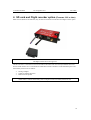
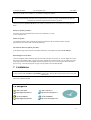
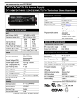
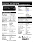
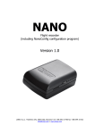
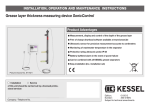
1
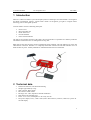
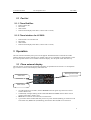
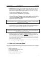
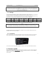
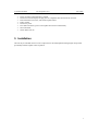
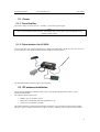
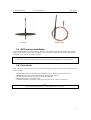
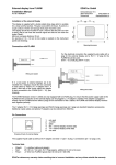
LX
Red Box
and Flarm interface for LX 5000
with optionally SD-card interface
User manual
Draft
1
2
3
4
5
6
7
Introduction ............................................................................................................................................ 3
Technical data......................................................................................................................................... 3
2.1 Part list ............................................................................................................................................. 4
2.1.1
Flarm Red Box........................................................................................................................ 4
2.1.2
Flarm interface for LX 5000................................................................................................... 4
Operation ................................................................................................................................................ 4
3.1 Flarm external display...................................................................................................................... 4
3.1.1
Settings ................................................................................................................................... 6
3.1.2
Installation .............................................................................................................................. 6
Firmware update..................................................................................................................................... 6
Installation .............................................................................................................................................. 7
5.1 Power ............................................................................................................................................... 8
5.1.1
Flarm Red Box........................................................................................................................ 8
5.1.2
Flarm interface for LX 5000................................................................................................... 8
5.2 RF antenna installation..................................................................................................................... 8
5.3 GPS antenna installation .................................................................................................................. 9
5.4 Final check ....................................................................................................................................... 9
SD card and Flight recorder option (Firmware 3.05 or later) ............................................................... 10
Limitations............................................................................................................................................ 11
LX Flarm Red Box
LX Navigation d.o.o.
Dec. 2006
1 Introduction
Flarm is a collision avoidance system developed by Flarm Technologies from Switzerland. LX Navigation
and Flarm Technologies signed a contract under which LX Navigation got rights to integrate Flarm
technology into LX Navigation products.
A Flarm module consists of following main parts.
•
•
•
•
•
GPS receiver
Microcontroller unit
Radio Transceiver
Pressure altimeter
Flarm external indicator
The GPS receiver defines position of the glider, the microcontroller is responsible for collision prediction
calculations and the transceiver is sending and receiving data.
Both units use the same electronic and are mechanically nearly identical. The only difference is power and
GPS antenna connection. Red Box is a completely stand alone solution and LX 5000 interface uses LX
5000 485 bus for power. Already installed LX 5000 GPS antenna will serve both units.
2 Technical data
•
•
•
•
•
•
•
•
Dimensions:50x27x97 mm aluminum housing
Weight: approximately 150 gr.
GPS connector: BNC female
RF connector: SMA female
RF range: max. 5 km, depends on antenna installation
Data interface 6P telephone type
Power : 8-16 V DC ,consumption ca. 60 mA by 12V DC
Pin 6 power input (8-16V), 4 and 1 GND (near to RF connector), 2 data in, 3 data out, 5 power for
external display
3
LX Flarm Red Box
LX Navigation d.o.o.
Dec. 2006
2.1 Part list
2.1.1 Flarm Red Box
•
•
•
•
Flarm red Box unit
RF antenna
GPS antenna
Flarm External display with cable (1x 60cm and 1x 150cm)
2.1.2 Flarm interface for LX 5000
•
•
•
•
Flarm Interface for LX 5000 unit
RF antenna
GPS antenna
Flarm External display with cable (1x 60cm and 1x 150cm)
3 Operation
The unit will run immediately after power will be applied. With GPS antenna connected and visible
satellites about three minutes will take to be operable. There are no commands or status indicators on the
unit. All important statuses are be readable on External display, also all inputs will be done this way.
3.1 Flarm external display
The unit consists of a 50x20 mm flat housing which has one push button and 16 LED’s. A 6P telephone
type connector connects External display with Flarm unit.
Warning/Nearest LED
Status LED
Mode selector
•
•
•
•
10 radial positioned red LED’s, defines direction to the near glider (top LED active means
frontal collision risk)
2 additionally red light emitting diodes marked like above and below informs about vertical
position of the glider, which is close.
Mode button is used to control the unit, see table below
5 green status LED’s. Power indicates presence of power and data (blinking, if no data received
from Flarm unit), GPS status (bad blinking), Tx transmit detection, Rx receive detection.
4
LX Flarm Red Box
LX Navigation d.o.o.
Dec. 2006
The external display has two modes of operation:
•
WARNING Mode will activate a red blinking diode, if another glider equipped with Flarm will
be close and a prediction for a collision risk will exist. An audio warning will be also executed.
Higher collision risk will increase blinking frequency and the same is with audio. The warnings
are classified into three levels (See Flarm manual for details)
-First level approximately 18 seconds before predicted collision
-Second level approximately 13 seconds before predicted collision
-Third level approximately 8 seconds before predicted collision
•
NEAREST Mode will show the direction to the nearest glider which position is inside of radio
range. One red LED will light permanently and there will be no audio. The unit will change over
to Warning Mode automatically, if warning criteria will be fulfilled and will continue in
NEAREST after collision risk will disappear.
Note!
The external displays produced by LX Navigation will change over to Demo mode after MODE button
will be pressed 10 times. Nearest mode and all possible warnings will be displayed. To change over back to
normal operation switch the unit off.
•
Pressing of MODE selector continuously for approximately 4 seconds will deactivate Flarm
external display for 5 minutes, no warnings and no near information will be displayed during this
period. A very typical situation only Power LED on, will characterize this status.
Note!
To change mode of operation press MODE button for approximately 2 seconds. If the radial LED’s will
run from top toward bottom means change over to NEAREST and vice versa. After new power on, the
mode active before switching off will remain.
•
Obstacles. Flarm electronic is capable to store coordinates of obstacles, which could cause a
collision during flight. This data is available on www.flarm.com, use Flarm tools to update. The
unit is factory loaded with actual obstacle database. An obstacle warning will be activated, if an
obstacle is to be found in the front of the glider and a collision risk is predicted.
After a low level warning has been activated two upper LEDs will be active (such a situation will
Newer appears by glider collision risk). Medium and high risk will be indicated with more LED’s
Active and more frequent audio signal.
•
To change audio warning volume press short mode selector, each press will increase audio
volume (three levels and mute available).
3.1.1 Dual color Flarm external display
The LX Flarm external displays delivered after June 2007 includes on any position two LEDs, one red and
one green. The manipulation remained unchanged. Following statuses are clearly displayed.
•
•
•
•
•
•
•
Power red flashing, no data from Flarm
Power green data received
GPS red GPS BAD, GPS green GPS OK/3D
Tx green flashing, data send
Rx green , minimum one glider in range
Green circular LED, indication f near gliders
Red flashing LED, collision warning
5
LX Flarm Red Box
LX Navigation d.o.o.
Dec. 2006
Note!
To change mode of operation press MODE button for approximately 2 seconds. If the radial LED’s will
run from top toward bottom means change over to NEAREST and vice versa. After each new power on,
the unit will start in Nearest mode.
3.1.2 Settings
Using of mode selector button is possible to adjust some parameters of the external display. Disconnect the
unit, press mode selector and hold, power on, hold mode selector for about 4 seconds.
The display parameters can be defined pressing mode selector for approximately 2 seconds and observing
green LED’s. To move in-between parameter press mode short and observe red LED’s.
Parameter
LED
Twin confg.
Baudrate
Tx
Tx+Rx
Red LED
018˚
˚
PIC
4800 bps
Red LED
054˚
˚
PAX
9600 bps
Red LED
090˚
˚
Red
LED126˚
˚
Red
LED162 ˚
Red LED
198˚
˚
19200 bps
-------
38400 bps
57600 bps
If two units will work in parallel (double seater), one unit must be PIC and another PAX.
Note!
LX Flarm Red Box and also Interface for LX 5000 baud rate is 19200. There isn’t any possibility to change
this parameter. All external displays delivered through LX Navigation are factory set to 19200.
If another navigation device for instance PDA is intended to be used, a splitter should be inserted. LX
Navigation offers a wide range of splitters.
3.1.3 Installation
Find a convenient place in the cockpit, which offers a good viewing angle to the LED’s. LX Navigation
offers a small housing which will make installation on the top of the instrument panel professional.
Two connection cables having different lenghts are offered to ensure all possible instalation solutions.
4 Firmware update
Flarm software expires and therefore periodically firmware upgrades are necessary. Flarm original tools
should be used, available on www.flarm.com. A cable set isn’t a part of delivery. Use IGC compatible
cables, for instance Colibri/LX20 power and data adapter.
The procedure:
6
LX Flarm Red Box
•
•
•
•
•
•
•
•
LX Navigation d.o.o.
Dec. 2006
Power on Flarm red box/Interface LX 5000
Disconnect External display and plug an IGC compatible cable into Flarm 6P connector
Run actual Flarm tool on PC, which offers update Flarm
Follow wizard
Disconnect power
Press button and hold, power on and update bar will start automatically
Wait until finish
Switch Flarm unit off
5 Installation
The unit may be installed wherever in the cockpit (doesn’t need manipulation during flight). Respect that
periodically firmware update will be requested.
7
LX Flarm Red Box
LX Navigation d.o.o.
Dec. 2006
5.1 Power
5.1.1 Flarm Red Box
Two wires coming out of the unit (red + and blue -) are used for power supply.
Note!
There is no internal fuse built in the unit. Use External fuse 1A. The unit is prevented against wrong
polarity of input voltage.
5.1.2 Flarm interface for LX 5000
Connect 9P SUB D to LX 5000 485system bus. Usually a free plug will be found on LCD Vario. In case of
no free connector a 485 splitter should be used (available by LX Navigation).
All other details match LX Flarm red box specifications.
5.2 RF antenna installation
The RF antenna installation should be taken serious; a bad positioned antenna may reduce system
parameters dramatically.
The antenna consists of three parts:
•
•
•
Radiator apr. 10 cm rubber coated
Back plane an aluminum plate having diameter 12 cm
Cable (60 cm) with SMA connector
The radiator should be vertical and the back plane horizontal. Use top positions on the instrument panel.
Having no space to install the antenna, use a dipole variant, available by LX Navigation or Flarm dealers.
8
LX Flarm Red Box
LX Navigation d.o.o.
λ/4 antenna
Dec. 2006
Dipole antenna
5.3 GPS antenna installation
The GPS antenna which is a part of delivery (Red Box only) should be installed somewhere in the cockpit
where a good satellite contact can be established. Never install the antenna close to another GPS antenna.
Minimum 15 cm of space diversity is required.
Note!
Flarm unit will not work until having GPS 3D, means antenna installation is an important fact.
5.4 Final check
After LX Flarm unit will receive power, the External display will pass initial routine which will take
several seconds.
1.Power LED indicates presence of power, blinking means no data received from Flarm unit
2.GPS LED informs about GPS status, blinking GPS bad, light GPS OK
3.Tx indicates transmission, only active by GPS OK (blinking)
4.Rx indicates presence of another Flarm
5. Check functionality of mode key, each short press will activate audio for a short time
Note!
After installation obligatory check functionality from 1 to 3 and 5.
9
LX Flarm Red Box
LX Navigation d.o.o.
Dec. 2006
6 SD card and Flight recorder option (Firmware 3.05 or later)
Both versions (Red box and Interface) may be delivered with SD card interface and flight recorder option.
Note!
The flight recorder hasn’t IGC approval.
The SD card slot is connected via 50 cm fixed cable to the Flarm unit. One already formatted SD card is
delivered with the unit. It is recommended to install SD card slot somewhere on the instrument panel. The
functionality of SD card is as follows:
•
•
•
Storing of flights
Update of obstacle data base
Flarm firmware update
Note!
Flarm traffic avoidance functionality does not depend on SD card status (inserted or not).
10
LX Flarm Red Box
LX Navigation d.o.o.
Dec. 2006
Files for any update are available on www.flarm.com/support/updates/.
Note!
FAT 32 formatted SD cards will no be accepted by the system. Use FAT 16 formatted cards, delivery
included card is already formatted and ready for operation.
All files should be copied to the SD card (no folders permitted), also it is not allowed to change any file
name.
Ready for update procedure:
-Insert the card and switch the Flarm unit off, for minimum 5 seconds
-Power on Flarm unit
Firmware update:
-An update will follow after a file having extension .fw will be detected; the procedure will take
approximately one minute and will run automatically.
The obstacle data base update procedure:
-If an .obs file type will be detected, an update will follow. The update may take several minutes.
Read of flight recorder data:
-The last 20 flights will be automatically copied to SD card after each power on. If some flights also exists,
they will not be doubled. After a longer time flying without the card inserted the copy procedure may take
some longer time because all 20 flights must be transferred to the card. To start copy to SD card remove
power for apr. 5 seconds and power on again. The procedure will run automatically.
7 Limitations
Note!
Using of Flarm will not reduce responsibility of the pilot to monitor the airspace and to react in case of a
collision risk.
See Flarm manual for details.
LX navigation
+ 386 3 490 4670
[email protected]
+ 386 3 490 46 71
http://www.lxnavigation.si
+ 49 89 32208653
[email protected]
+ 49 89 32208654
http://www.lxnavigation.de
11
LX Flarm Red Box
LX Navigation d.o.o.
Dec. 2006
12