1
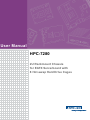
User Manual HPC-7280 2U Rackmount Chassis for EATX Serverboard with 8 Hot-swap Hard Drive Cages Copyright The documentation and the software included with this product are copyright 2011 by Advantech Co., Ltd. All rights are reserved. Advantech Co., Ltd. reserves the right to make improvements in the products described in this manual at any time without notice. No part of this manual may be reproduced, copied, translated or transmitted in any form or by any means without the prior written permission of Advantech Co., Ltd. Information provided in this manual is intended to be accurate and reliable. However, Advantech Co., Ltd. assumes no responsibility for its use, nor for any infringements of the rights of third parties, which may result from its use. Acknowledgements HPC-7280 is a trademark of Advantech Co., Ltd. All other product names or trademarks are properties of their respective owners. On-line Technical Support For technical support and service, please visit our support website at: http://www.advantech.com/support Product Warranty (2 years) Advantech warrants to you, the original purchaser, that each of its products will be free from defects in materials and workmanship for two years from the date of purchase. This warranty does not apply to any products which have been repaired or altered by persons other than repair personnel authorized by Advantech, or which have been subject to misuse, abuse, accident or improper installation. Advantech assumes no liability under the terms of this warranty as a consequence of such events. Because of Advantech’s high quality-control standards and rigorous testing, most of our customers never need to use our repair service. If an Advantech product is defective, it will be repaired or replaced at no charge during the warranty period. For outof-warranty repairs, you will be billed according to the cost of replacement materials, service time and freight. Please consult your dealer for more details. If you think you have a defective product, follow these steps: 1. Collect all the information about the problem encountered. (For example, CPU speed, Advantech products used, other hardware and software used, etc.) Note anything abnormal and list any onscreen messages you get when the problem occurs. 2. Call your dealer and describe the problem. Please have your manual, product, and any helpful information readily available. 3. If your product is diagnosed as defective, obtain an RMA (return merchandise authorization) number from your dealer. This allows us to process your return more quickly. 4. Carefully pack the defective product, a fully-completed Repair and Replacement Order Card and a photocopy proof of purchase date (such as your sales receipt) in a shippable container. A product returned without proof of the purchase date is not eligible for warranty service. 5. Write the RMA number visibly on the outside of the package and ship it prepaid to your dealer. HPC-7280 User Manual Part No. 2006C72800 Edition 1 Printed in Taiwan November 2011 ii Safety Instructions 1. 2. 3. 4. 5. 6. 7. 8. 9. 10. 11. 12. 13. 14. 15. 16. 17. 18. 19. Read these safety instructions carefully. Keep this User Manual for later reference. Disconnect this equipment from any AC outlet before cleaning. Use a damp cloth. Do not use liquid or spray detergents for cleaning. For plug-in equipment, the power outlet socket must be located near the equipment and must be easily accessible. Keep this equipment away from humidity. Put this equipment on a reliable surface during installation. Dropping it or letting it fall may cause damage. Do not leave this equipment in an environment unconditioned where the storage temperature under 0°C (32°F) or above 40°C (104°F), it may damage the equipment. The openings on the enclosure are for air convection. Protect the equipment from overheating. DO NOT COVER THE OPENINGS. Make sure the voltage of the power source is correct before connecting the equipment to the power outlet. Position the power cord so that people cannot step on it. Do not place anything over the power cord. All cautions and warnings on the equipment should be noted. If the equipment is not used for a long time, disconnect it from the power source to avoid damage by transient overvoltage. Never pour any liquid into an opening. This may cause fire or electrical shock. Never open the equipment. For safety reasons, the equipment should be opened only by qualified service personnel. If one of the following situations arises, get the equipment checked by service personnel: The power cord or plug is damaged. Liquid has penetrated into the equipment. The equipment has been exposed to moisture. The equipment does not work well, or you cannot get it to work according to the user's manual. The equipment has been dropped and damaged. The equipment has obvious signs of breakage. Caution: The computer is provided with a battery-powered real-time clock circuit. There is a danger of explosion if battery is incorrectly replaced. replace only with same or equivalent type recommended by the manufacture. discard used batteries according to the manufacturers instructions. THE COMPUTER IS PROVIDED WITH CD DRIVES COMPLY WITH APPROPRIATE SAFETY STANDARDS INCLUDING IEC 60825. CLASS 1 LASER PRODUCT KLASSE 1 LASER PRODUKT This device complies with Part 15 of the FCC rules. Operation is subject to the following two conditions: (1) this device may not cause harmful interference, and (2) this device must accept any interference received, including interference that may cause undesired operation Caution: Always completely disconnect the power cord from your chassis whenever you work with the hardware. do not make connections while the power is on. sensitive electronic components can be damaged by sudden power surges iii HPC-7280 User Manual 20. Caution: Always ground yourself to remove any static charge before touching the motherboard, backplane, or add-on cards. modern electronic devices are very sensitive to static electric charges. as a safety precaution, use a grounding wrist strap at all times. place all electronic components on a static-dissipative surface or in a static-shielded bag when they are not in the chassis 21. Caution: Any unverified component could cause unexpected damage. to ensure the correct installation, please always use the components (ex. screws) provided with the accessory box. A Message to the Customer Advantech customer services Each and every Advantech product is built to the most exacting specifications to ensure reliable performance in the harsh and demanding conditions typical of industrial environments. Whether your new Advantech equipment is destined for the laboratory or the factory floor, you can be assured that your product will provide the reliability and ease of operation for which the name Advantech has come to be known. Your satisfaction is our primary concern. Here is a guide to Advantech's customer services. To ensure you get the full benefit of our services, please follow the instructions below carefully. Technical support We want you to get the best performance possible from your products. If you run into technical difficulties, we are here to help. For the most frequently asked questions, you can easily find answers in your product documentation. These answers are normally a lot more detailed than the ones we can give over the phone. Please consult this manual first. If you still cannot find the answer, gather all the information or questions that apply to your problem, and with the product close at hand, call your dealer. Our dealers are well trained and ready to give you the support you need to get the most from your Advantech products. In fact, most problems reported are minor and can be easily solved over the phone. In addition, free technical support is available from Advantech engineers every businessday. We are always ready to give advice about application requirements or specific information on the installation and operation of any of our products. HPC-7280 User Manual iv Initial Inspection When you open the carton, please make sure that the following materials have been shipped: Chassis – 1 x HPC-7280 Chassis Components – 1 x 800 W (1+1) redundant power supply – 3 x 80*38 mm 4-pin PWM fan (middle) – 8 x HDD tray – 1 x SAS/SATA hard drive backplane – 1 x Front I/O panel board – 1 x Front bezel with key Accessories – 1 x Startup manual – 1 x Warranty card – 1 x Accessory box with a package of screws – 2 x Key of HDD Tray If any of these items are missing or damaged, contact your distributor or sales representative immediately. We have carefully inspected the HPC-7280 mechanically and electrically before shipment. It should be free of marks and scratches and in perfect working order upon receipt. As you unpack the HPC-7280, check it for signs of shipping damage. (For example, damaged box, scratches, dents, etc.) If it is damaged or it fails to meet the specifications, notify our service department or your local sales representative immediately. Also, please notify the carrier. Retain the shipping carton and packing material for inspection by the carrier. After inspection, we will make arrangements to repair or replace the unit. v HPC-7280 User Manual HPC-7280 User Manual vi Contents Chapter 1 General Information ............................1 1.1 1.2 1.3 Introduction ............................................................................................... 2 Specifications ............................................................................................ 2 Power Supply Specifications..................................................................... 2 Table 1.1: Power supply .............................................................. 2 Environment Specifications....................................................................... 2 Table 1.2: Environment specifications......................................... 2 Dimension Diagram................................................................................... 3 Figure 1.1 Dimension Diagram .................................................... 3 1.4 1.5 Chapter 2 System Setup .......................................5 2.1 2.2 Overview ................................................................................................... 6 Removing the Chassis Cover.................................................................... 6 2.2.1 Disconnecting the Chassis from the Power Source...................... 6 2.2.2 Removing the Chassis Cover ....................................................... 6 Figure 2.1 Removing the Chassis Cover ..................................... 6 Accessing the Hot-Swappable Drive Trays............................................... 7 2.3.1 Accessing and Installing Hard Drives ........................................... 7 Figure 2.2 Removing Hard Drive Trays ....................................... 7 Installing Fixed Hard Drives in HPC-7280 Chassis Models ...................... 7 2.4.1 Disconnecting the Chassis from the Power Source...................... 7 Figure 2.3 Removing Hard Drive Trays ....................................... 7 Installing Hard Drives into the Drive Trays................................................ 8 2.5.1 Installing Hard Drives.................................................................... 8 Figure 2.4 Hard Drive Trays ........................................................ 8 Installing Slim CD-ROM/DVD ROM .......................................................... 8 2.6.1 Storage Module Options ............................................................... 8 Removing and Replacing the System Fans .............................................. 9 2.7.1 Standard Cooling Systems ........................................................... 9 Figure 2.5 Removing the Middle Chassis Fans ........................... 9 Installing the Motherboard......................................................................... 9 2.8.1 Prior to Installing the Motherboard................................................ 9 2.8.2 Motherboard Installation ............................................................... 9 Figure 2.6 Installing the Motherboard ........................................ 10 2.3 2.4 2.5 2.6 2.7 2.8 Chapter 3 Operation............................................11 3.1 3.2 3.3 The Front Panel ...................................................................................... 12 3.1.1 Switch, Button and I/O Interfaces ............................................... 12 3.1.2 LED Indicators for System Status ............................................... 12 Figure 3.1 Front control panel.................................................... 12 Control Panel Buttons ............................................................................. 13 Control Panel LEDs................................................................................. 13 4 1U 4Bay SAS Backplane ...................15 4.1 Instruction Guide ..................................................................................... 16 Appendix A Chassis Screws .................................19 A.1 Chassis Screws....................................................................................... 20 Chapter vii HPC-7280 User Manual HPC-7280 User Manual viii Chapter 1 1 General Information 1.1 Introduction HPC-7280 is a 2U rackmount industrial computer chassis for high-performance and high-capacity computing applications. It meets a variety of application needs for filing, printing, e-mail and web serving. This powerful computing platform is suitable for mission-critical computer telephony applications, industrial automation, and factory management. A wide range of standard computing peripherals can be integrated with the chassis to meet different application needs for operation under harsh conditions 24 hours a day, 7 days a week. 1.2 Specifications Construction: Heavy-duty steel Disk Drive Capacity: One slim-type ODD Bay LED Indicators on Front Panel: Bi-color LEDs (green/red) for power, temperature, and fan status; single-color LEDs (green) for HDD activity and LAN status Switch and Button on Front Panel: Power switch, system reset button Front I/O Interfaces: One USB port Cooling System: Three 80 mm x 38 mm hot-swappable cooling fans Weight: 28 kg Dimensions (W x H x D): 482.6 x 88 x 700 mm 1.3 Power Supply Specifications Table 1.1: Power supply Model 1+1 800 W redundant power supply Watt 800 W AC-DC power supply Input Rating 100 - 240 V, 50-60 Hz, 10-5 Amp Output Voltage +3.3 V @ 32 A, +5V @ 32 A, 5 Vsb @ 3.5 A, +12 V @ 65 A, -12 V @ 0.8 A Safety UL/TUV/CB/CCC 1.4 Environment Specifications Table 1.2: Environment specifications Environment Operating Non-operating Temperature 0° C ~ 40° C -40° C ~ 70° C Humidity 10 ~ 85% @ 40° C Non-Condensing 10 ~ 85% @ 40° C Non-Condensing HPC-7280 User Manual 2 Chapter 1 1.5 Dimension Diagram unit: mm 736.70 36.80 482.40 Figure 1.1 Dimension Diagram 3 HPC-7280 User Manual General Information 701.40 432.20 HPC-7280 User Manual 4 Chapter 2 System Setup 2 2.1 Overview The following procedures instruct users on how to install a backplane/motherboard, add-on cards and disk drives into the HPC-7280. Caution! Use caution when installing or operating the components with the chassis open. Be sure to turn off the power, unplug the power cord and ground yourself by touching the metal chassis before you handle any components inside the machine. 2.2 Removing the Chassis Cover 2.2.1 Disconnecting the Chassis from the Power Source 1. 2. 3. Turn off all peripheral devices and turn off the power supply to the HPC-7280. Disconnect the AC power cords from the system. Disconnect all cables and label the cables for easy identification. Warning! Use a grounded wrist strap designed to prevent static discharge when handling components. After completing the above steps, you can remove the chassis cover and install components and devices into the chassis as described in this chapter. 2.2.2 Removing the Chassis Cover 1. 2. 3. Release 2 thumb screws from rear panel & 2 screws from both sides. Push the cover forward to open the rear-top cover. Release 2 thumb screws from both sides & 2 screws from the mid-top cover. Lift the cover up to open the mid-top cover. Release 2 screws on the front-top cover. Push the top cover forward to open the front-top cover. Figure 2.1 Removing the Chassis Cover HPC-7280 User Manual 6 Hot-swappable drives may be removed and installed from the chassis without powering-down the system and without opening the chassis cover. 2.3.1 Accessing and Installing Hard Drives 1. 2. Figure 2.2 Removing Hard Drive Trays 2.4 Installing Fixed Hard Drives in HPC-7280 Chassis Models 2.4.1 Disconnecting the Chassis from the Power Source 1. 2. 3. 4. 5. 6. 7. 8. Turn off all peripheral devices and turn off the power supply to the HPC-7280. Disconnect the AC power cord from the system. Disconnect all cables and label the cables for easy identification. Open the chassis cover as described in section 2.2. Disconnect the wiring which the hard drive to either the motherboard or the expansion card of the motherboard, depending upon your chassis model. Unlock and open the drive tray door as shown. Place the 3.5” HDD on the cage and fix HDD with 4 screws from both sides of HDD tray. Insert the drive carrier into its bay. Push the tray lever until it clicks. Make sure the drive tray is correctly secured in place with its front edge aligned with the bay edge. Figure 2.3 Removing Hard Drive Trays 7 HPC-7280 User Manual System Setup 3. 4. Unlock and open the drive tray door as shown. Press the release tab located on the drive tray door to release the drive tray from its locked position. Lift up the drive tray handle. Pull the drive tray door downward and pull the drive tray out from the chassis. (Note: The orientation of the picture shown below is for rack mount systems.) Chapter 2 2.3 Accessing the Hot-Swappable Drive Trays 2.5 Installing Hard Drives into the Drive Trays 2.5.1 Installing Hard Drives 1. Place the 3.5” HDD on the cage and fix HDD with 4 screws from both sides of HDD tray. 2. Insert the drive carrier into its bay. Push the tray lever until it clicks. Make sure the drive tray is correctly secured in place when its front edge aligns with the bay edge. *All 3.5” hot-swap HDD can also fit 2.5” HDD or SSD by additional 2.5” HDD converted bracket purchasing. Figure 2.4 Hard Drive Trays 2.6 Installing Slim CD-ROM/DVD ROM 2.6.1 Storage Module Options 1. 2. 3. 4. 5. 6. Insert Slim CD-ROM/DVD-ROM SATA cable through B/P bracket. Connect Slim CDROM/DVD-ROM SATA cable with the Slim CD-ROM/DVDROM. Release thumb screw to remove the Slim CD-ROM/DVD-ROM holder bracket. Remove Slim CD-ROM /DVD-ROM dummy plate. There are 2 pins on chassis as shown. Align the Slim CD-ROM/DVD-ROM into pins. Align these 2 pins of Slim CD-ROM/DVD-ROM holder bracket into the left of Slim CD-ROM/DVD-ROM & tighten the thumb screw. 1 5 4 HPC-7280 User Manual 3 2 8 6 Before installing the motherboard in the chassis or accessing the motherboard after installation, it is necessary to remove the system fans. One set is located at the rear of the chassis, the other set is located in the middle of the chassis. 2.7.1 Standard Cooling Systems Figure 2.5 Removing the Middle Chassis Fans 2.8 Installing the Motherboard 2.8.1 Prior to Installing the Motherboard Identify the locations of the following components: Processor(s) Mounting holes Retention brackets Type A screws (included in the chassis accessory kit) Obtain the following parts for the motherboard being used. These should be included with the motherboard. (Refer to the motherboard documentation for details) I/O shield Chassis standoffs Heatsink retention brackets 2.8.2 Motherboard Installation Installing the Motherboard 1. Disconnect the power supply. 2. Lay the chassis on a flat surface. 3. Locate the mounting holes on the chassis. 4. Install the standoffs into the holes in the chassis. 5. Install the I/O shield as directed by the motherboard documentation. 6. Secure the heatsink to the motherboard as directed by the motherboard documentation. 7. Secure the motherboard to the chassis using Type A screws, which are included in the chassis accessory kit. Do not exceed eight pounds of torque per square inch when tightening down the motherboard. 9 HPC-7280 User Manual System Setup HPC-7280 chassis include mid-chassis cooling fans, rear cooling fans to channel air within the chassis. Removing and Replacing Mid-chassis Fans 1. Release 2 thumb screws from both sides & 2 screws from the mid-top cover. 2. Lift the cover up to open the mid-top cover. Chapter 2 2.7 Removing and Replacing the System Fans Figure 2.6 Installing the Motherboard Warning! The system fans and chassis cover must be installed prior to operating the system. Out-of-warranty damage may result if the system is operated without proper cooling protection in place. HPC-7280 User Manual 10 Chapter 3 Operation 3 3.1 The Front Panel The front panel features a lockable door. The user can close the door with or without the key using the user-friendly rotary lock. Upon opening the door, one sees eight 3.5" SAS/SATA hot-swap hard drive trays. There is a momentary power switch, two reserved system reset buttons, one USB ports, and four LED indicators. Their individual functions are described below. 3.1.1 Switch, Button and I/O Interfaces Momentary Power switch: Press this switch to turn the system power on or off. Please use system shutdown or press this switch for few seconds to turn off the system ATX power. System Reset button: Press this button to reboot the system. USB ports: For connecting a wide range of USB devices for data transfer, backup, input, etc. 3.1.2 LED Indicators for System Status The following diagram identifies components on the front LED panel. Figure 3.1 Front control panel 1. 2. 3. 4. 5. 6. 7. LAN2 LED LAN1 LED System HDD Activity LED Power LED System reset button Power on/off button Front access USB port HPC-7280 User Manual 12 There are two push-buttons located on the front of the chassis. These are (in order from left to right) a reset button and a power on/off button. Power: The main power switch is used to apply or remove power from the power supply to the server system. Turning off system power with this button removes the main power but keeps standby power supplied to the system. Therefore, you must unplug system before servicing. Reset: The reset button is used to reboot the system. 3.3 Control Panel LEDs The control panel located on the front of the HPC-7280 chassis has five LEDs. These LEDs provide you with critical information related to different parts of the system. This section explains what each LED indicates when illuminated and any corrective action you may need to take. PWR Power: The main power switch is used to apply or remove power from the power supply to the server system. Turning off system power with this button removes the main power but keeps standby power supplied to the system. Therefore, you must unplug the system's power cord before servicing. HDD: Indicates IDE channel activity. SAS/SATA drive, SCSI drive, and/or DVDROM drive activity when flashing. NIC1: Indicates network activity on GLAN1 when flashing. NIC2: Indicates network activity on GLAN2 when flashing. 13 HPC-7280 User Manual Operation Chapter 3 3.2 Control Panel Buttons HPC-7280 User Manual 14 Chapter 4 1U 4Bay SAS Backplane 4 4.1 Instruction Guide HDD1 HDD2 HDD3 CN7 CN6, CN7: 4 Pin Power connector for +12 V and +5 V Power input JP1: External HDD Accessing LED Input (Active Low) Pin Description 1 GND 2 HDD1 3 HDD2 4 HDD3 5 HDD4 JP2: External HDD Fail LED Input (Active Low) Pin Description 1 GND 2 HDD1 3 HDD2 4 HDD3 5 HDD4 J2: Function Select Pin 1, 2 3, 4 5, 6 7, 8 Status Description Open Disable External Access LED input (JP1) Close Enable External Access LED input (JP1) Open Access LED from HDD Pin P11 Close Access LED from SGPIO Open SGPIO Bit2 is HDD Fail, Bit3 is HDD ID Close SGPIO Bit2 is HDD ID, Bit3 is HDD Fail Open Disable SGPIO Close Enable SGPIO HPC-7280 User Manual 16 HDD4 CN5: Mini SAS 36pin Pin No. Signal Pin No. Rx 0+ A2 Tx 0+ B2 Rx 0- A3 Tx 0- B3 Rx 1+ A5 Tx 1+ B5 Rx 1- A6 Tx 1- B6 Sideband 0 A8 Sideband 7 B8 Sideband 1 A9 Sideband 3 B9 Sideband 2 A10 Sideband 4 B10 Sideband 6 A11 Sideband 5 B11 Rx 2+ A13 Tx 2+ B13 Rx 2- A14 Tx 2- B14 Rx 3+ A16 Tx 3+ B16 Rx 3- A17 Tx 3- B17 Signal A1, A4, A7, A12, A15, A18 Ground B1, B4, B7, B12, B15, B18 Note! 1. 2. 3. The 4in1 SAS backplane is designed for SGPIO supported through sideband. (CN5) User also can get the HDD accessing/fail LED signal from the HBA/ RAID card. (JP1, JP2) Please set the J2 properly before related signal linking. 17 HPC-7280 User Manual 1U 4Bay SAS Backplane Signal Chapter 4 J1: Firmware Update (Factory use only) HPC-7280 User Manual 18 Appendix A Chassis Screws A A.1 Chassis Screws The accessory box includes all the screws needed to setup your chassis. This section lists and describes the most common screws used. Your chassis may not require all the parts listed. M/B HARD DRIVE Flat head 6-32 x 5 mm [0.197] Pan head 6-32 x 5 mm [0.197] DVD-ROM, CD-ROM, and FLOPPY DRIVE Pan head 6-32 x 5 mm [0.197] Flat head 6-32 x 5 mm [0.197] Round head M3 x 5 mm [0.197] Round head M2.6 x 5 mm [0.197] RAIL Flat head M4 x 4 mm [0.157] Round head M4 x 4 mm [0.157] Flat head M5 x 12 mm[0.472] Washer for M5 M/B STANDOFFS M/B standoff 6-32 to 6-32 HPC-7280 User Manual M/B (CPU) standoff M5 to 6-32 Thumb screw 6-32 x 5 mm [0.197] 20 1/U M/B standoff 6-32 x 5 mm [0.197] Appendix A Chassis Screws HPC-7280 User Manual 21 www.advantech.com Please verify specifications before quoting. This guide is intended for reference purposes only. All product specifications are subject to change without notice. No part of this publication may be reproduced in any form or by any means, electronic, photocopying, recording or otherwise, without prior written permission of the publisher. All brand and product names are trademarks or registered trademarks of their respective companies. © Advantech Co., Ltd. 2011