1
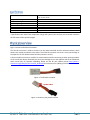
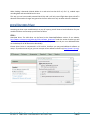
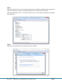
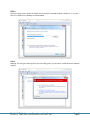
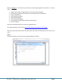
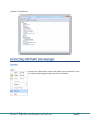
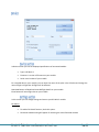
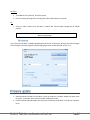
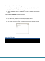
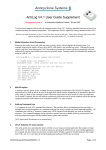
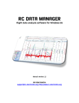
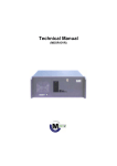
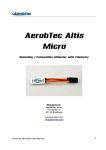
Key features .............................................................................................................................................. 3 How it works ............................................................................................................................................. 3 Specifications ............................................................................................................................................ 4 Powering the module................................................................................................................................ 5 Mounting the module ............................................................................................................................... 5 Operation .................................................................................................................................................. 5 Connect ................................................................................................................................................... 10 Device...................................................................................................................................................... 11 Device section ..................................................................................................................................... 11 Settings section ................................................................................................................................... 11 FAI version........................................................................................................................................... 12 The RC Multi 2 module was designed to provide a lightweight compact device for measuring and recording flight data over time. It was designed especially for use on board a radio controlled (R/C) aircraft, but would be useful in other applications too. The RC Multi 2 module is able to record data from various inbuilt sensors for later review on PC. It can also transmit flight data via RC TRX30 module to the ground unit as a “live” telemetry system. For communication with PC it uses a standard USB port with the supplied lead. It uses state of art pressure sensor and 3MByte nonvolatile flash memory for data storage. Lightweight at only 6 grams with JR cables. Small: 28 mm x 14 mm x 6 mm. Integrated F5J FAI altitude/time switch. 21 hours of recording time with a 10Hz-sampling rate of all data. Records various flight data for later review. PC USB interface for configuration, loading firmware updates and downloading recorded data. Wide range of input power: 4 – 10 volts DC. Normally taking power from your aircraft receiver supply. The RC Multi 2 module uses a high-resolution barometric pressure sensor system to detect small changes in air pressure that occur due to changes in altitude. It is sensitive enough to detect altitude changes of less than 20cm. This also makes it sensitive to changes in local weather and air pressure variations. The intended use of this device is for measuring short-term altitude changes in R/C aircraft. Long-term altitude readings will vary considerably due to varying atmospheric conditions. It is best used to measure relative changes in altitude. Module has a 10 pin bus connector with different protocol defined pins (USB, I2C, UART, I/O, ADC) to which various sensors and modules can be connected (GPS, TEK sensor, RC TRX30 transceiver, and many more). All connected modules/sensors are “plug and play”. All new sensors will be supported in future firmware. For storing data, the RC Multi 2 module has a nonvolatile flash memory chip with 3MByte capacity. For precise review of data, the module saves data at a 10Hz saving rate. Board Dimensions 28 mm x 14 mm x 6 mm 1.10” x 0.55” x 0.24” 6 grams -10°C ~ +60°C 4.0 – 10.0 volts DC 36 milliamps 4.0 – 10.0 volts DC Altitude, vario, servo pulse, temperature, battery voltage 3MByte Weight 1 Temperature Range Input Voltage Range Input Current Measured Voltage Basic recorded data Memory capacity 1 Specifications are taken from component ratings and system limits and may not have been tested to the full extent of the specified ranges. Figure 1 shows the RC Multi 2 hardware. The JR male connector is used to connect it to the radio-controlled aircraft’s onboard receiver, which powers the module and detects servo pulse. The JR female connector serves as a servo pass-through or as output for the F5J altitude switch function (connect it to ESC). A 10 pin modular connector is used for PC communication and for connecting to other sensors/modules. It has a small push button located by the servo pass through wire on the opposite side of the PCB board, which serves only for firmware uploading. Please see the RC unit Update manual http://www.rcelectronics.org/index.php?link=manual_download for instructions for updating firmware. Figure 1: The RC Multi 2 module. Figure 2: Location of the firmware button. To power the RC Multi 2 module ON, plug the 3 pin male connector cable into the throttle channel on the R/C aircraft receiver and then plug the ESC/servo into the RC Multi 2 servo pass-through female connector. If you do not require control of the motor/height limit function, you can plug the RC Multi 2 into any free channel on the receiver. Be sure to observe proper polarity when plugging the connector into the receiver. For non-R/C use attach a battery of the correct voltage to the servo pass-through connector. A JST style connector can plug directly into the 3 pin pass-through female connector. Again, be sure to observe proper polarity or damage may result. The 3 pin pass-through female connector is oriented with the same polarity as the adjacent servo wires. The module can be mounted in one of two ways: The recommended method is inside the fuselage of the aircraft. In this case, there should be an opening of at least 0.5 sq. cm to allow air pressure inside the fuselage to equalize with the atmospheric pressure outside the aircraft. In many aircrafts, the fuselage is not airtight and is sufficiently vented to the outside air. On the outside of the aircraft. In this case, the pressure sensor should be at the right angle to the airflow for maximum accuracy. This means the air stream is flowing across the hole in the pressure sensor and not directly into or away from it. If possible, mount it away from the prop wash, because the measured altitude can increase by over 60 meters due to airflow from the prop. The module can be mounted using double-sided tape, cable ties or Velcro. Velcro is recommended, so that the module can be removed and interfaced with the PC for downloading flight data. Be sure that the module is not touching any metal surfaces. Although unlikely, there is a possibility of shorting the metal contacts on the module, which could result in a radio system failure. Do not mount the module on top of power batteries when using electric planes, because they get hot and this can affect the altitude readings by up to 30m. Also be sure to keep the module away from water, fuel and other liquids. Always range check and test the aircraft’s radio systems before flying with the RC Multi 2 module installed, to verify that all connections have been made correctly and there is no system interference. Each time you turn the module ON, it will set zero altitude and start logging data to circular buffer. When take-off is detected (vario is more than 0.5 m/s for 2 s), history data is saved to flash memory. History data is 8 s long. In flight, module saves all data from connected sensors/modules to onboard memory. When landing is detected (altitude bellow 4 m and vario less than 0.15 m/s for 5 s), module stops recording data and sets altitude back to zero. This way you can have module powered ON all day and it will only record flight data when take-off is detected. Also weather changes are ignored as the zero reference is only set when take off is detected. Assuming you have never used RC Multi 2 on your PC system, you will have to install USB driver for your module and there are few steps you will have to follow. STEP 1 Download driver: The USB driver can be found at the Download/Software section of our website: http://www.rc-electronics.org/index.php?link=software_download. Under the section Product you will find the RC Multi USB driver. Download it and save the file (we recommend you use a dedicated folder on the desktop for all RC Electronics downloads). Extract driver: Driver is compressed in a ZIP archive, therefore you may need additional software to unzip it. If you do not use any yet, you can use open source software called 7-zip (http://www.7-zip.org). STEP 2 Plug your RC Multi 2 into your PC using the provided 10 pin to USB cable. Windows device manager will find the unit but will not be able to locate suitable software. Follow the instructions below. Open Device Manager: There is a new device found. Click on it with right mouse button and Update Driver Software. STEP 3 Search for driver: Select browse my computer for driver software. STEP 4 Search for driver: Now, browse for folder where you have extracted RC Multi USB driver. In my case, I have it in a folder on my desktop as recommended. STEP 5 Warning: You may get a warning which you can safely ignore; you can select ‘install this driver software anyway’. Warning Windows 8: “The third-party INF does not contain digital signature information.” Use these steps: 1. 2. 3. 4. 5. 6. 7. 8. Bring on the “charm bar” (right side of the screen) and click on Settings. Click on Power, hold the shift key down on your keyboard and click on Restart. Choose Troubleshoot. Choose Advanced options. Select Startup Settings. Click on the Restart button. Hit the number 7 (Disable driver signature enforcement). Restart computer. After restart, Windows 8 will let you install the needed driver(s). The video presentation can be seen on http://www.youtube.com/watch?v=Nx7uJe6kqec. This step by step tutorial was written with help of the video above and thanks goes to the owner of the video. STEP 6 Finish the procedure: Your driver was successfully updated. Click Close. RC Multi 2 is ready for use! Connect your module with a proper cable (USB to 10 pin connector) to your PC. Open RC Data Manager program and click on File/Device. In Device section you can see displayed specifications of connected module: Type: is RC Multi 2. Firmware: is version of firmware on your module. Serial: serial number of your module. For recorded data on your module, you can write the name of the pilot in the Pilot box and change the name of flight in Flight box. All flights will be affected. Download button will download recorded flight data from your module. Erase button will erase flight data on your module. In this section you can change settings and save to your RC Multi 2 module. FXJ Switch: To enable FXJ Switch function, check this option. FXJ Switch Altitude setting will appear for selecting the value of desired altitude. FXJ Time: To enable FXJ Time function, check this option, FXJ Time setting will appear for selecting the value of desired time in seconds. Select on which channel your RC Multi 2 module will transmit data through the RC TRX30 module. RF: Note that RC Multi 2 will not remember selected settings and values until you press Write settings button. If you have your RC Multi 2 module uploaded with FAI version of firmware, settings cannot be changed. The next figure illustrates progress of downloading flight from module with FAI version on it. 1. Download latest firmware for RC Multi 2 from our web site. Firmware should start with name RC_Multi_2_vXXX.bin. XXX is version number (108 means v1.08). 2. Connect special USB cable 10pin connector (part of delivery) to RC Multi 2, but do not connect it to PC! If you have uploaded v1.08 or earlier use following procedure: Press update button, see figure 2, which is located on the other side of the JR cable and hold it pressed. When button is pressed, connect the USB to PC. LED on the RC Multi 2 should not turn ON. If LED is ON, disconnect USB from PC and try again. You can release button and wait for 15s. New disk drive (figure 3) will appear with firmware.bin file on it. If you have uploaded v1.09 or later use following procedure: Connect USB to PC (LED on RC Multi 2 must turn ON). Press update button, see figure 1, and new disk drive must appear (figure 2). Delete firmware.bin file and copy latest firmware file to this disk drive. When you see new FW file on this disk, you can disconnect USB from PC and update is finished. Figure 3: New disk drive. Januar 2012 December 2012 September 2013 Initial release of user manual. Added update instructions, connecting with RC Data Manager, installing of USB driver. Resolved installing USB driver on Windows 8.