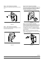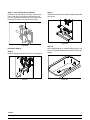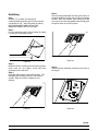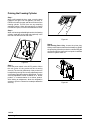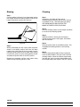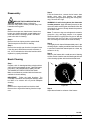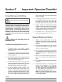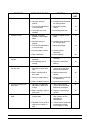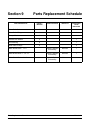
1
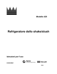
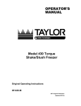
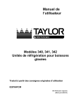
OPERATOR’S
MANUAL
Model 428
Shake/Slush Freezer
Original Operating Instructions
055058- M
February, 2001 (Original Publication)
(Updated 4/27/15)
Complete this page for quick reference when service is required:
Taylor Distributor:
Address:
Phone:
Service:
Parts:
Date of Installation:
Information found on the data label:
Model Number:
Serial Number:
Electrical Specs:
Voltage
Cycle
Phase
Maximum Fuse Size:
A
Minimum Wire Ampacity:
A
E 2001 Carrier Commercial Refrigeration, Inc.
055058- M
Any unauthorized reproduction, disclosure, or distribution of copies by any person of any portion of this work may be
a violation of Copyright Law of the United States of America and other countries, could result in the awarding of Statutory
Damages of up to $250,000 (17 USC 504) for infringement, and may result in further civil and criminal penalties.
All rights reserved.
Taylor Company
a division of Carrier Commercial Refrigeration, Inc.
750 N. Blackhawk Blvd.
Rockton, IL 61072
Table of Contents
Section 1
To the Installer . . . . . . . . . . . . . . . . . . . . . . . . . . . . . . . . . . . . . . . . . . . .
1
Section 2
To the Operator . . . . . . . . . . . . . . . . . . . . . . . . . . . . . . . . . . . . . . . . . . .
4
Section 3
Safety . . . . . . . . . . . . . . . . . . . . . . . . . . . . . . . . . . . . . . . . . . . . . . . . . . . .
5
Section 4
Operator Parts Identification . . . . . . . . . . . . . . . . . . . . . . . . . . . . . . .
7
Model 428 . . . . . . . . . . . . . . . . . . . . . . . . . . . . . . . . . . . . . . . . . . . . . . . . . . . . . . . . . . . .
7
Beater Door Assembly With Standard Door (No Prime Plug) . . . . . . . . . . . . . . . .
8
Beater Door Assembly With Self- Closing/Prime Plug Door . . . . . . . . . . . . . . . . .
10
Section 5
Important: To the Operator . . . . . . . . . . . . . . . . . . . . . . . . . . . . . . . . .
13
Section 6
Operating Procedures . . . . . . . . . . . . . . . . . . . . . . . . . . . . . . . . . . . . .
15
Assembly . . . . . . . . . . . . . . . . . . . . . . . . . . . . . . . . . . . . . . . . . . . . . . . . . . . . . . . . . . . .
15
Sanitizing . . . . . . . . . . . . . . . . . . . . . . . . . . . . . . . . . . . . . . . . . . . . . . . . . . . . . . . . . . . .
23
Priming the Freezing Cylinder . . . . . . . . . . . . . . . . . . . . . . . . . . . . . . . . . . . . . . . . . . .
24
Closing Procedure . . . . . . . . . . . . . . . . . . . . . . . . . . . . . . . . . . . . . . . . . . . . . . . . . . . .
25
Draining Product From The Freezing Cylinder . . . . . . . . . . . . . . . . . . . . . . . . . . . .
25
Rinsing . . . . . . . . . . . . . . . . . . . . . . . . . . . . . . . . . . . . . . . . . . . . . . . . . . . . . . . . . . . . . .
26
Cleaning . . . . . . . . . . . . . . . . . . . . . . . . . . . . . . . . . . . . . . . . . . . . . . . . . . . . . . . . . . . . .
26
Disassembly . . . . . . . . . . . . . . . . . . . . . . . . . . . . . . . . . . . . . . . . . . . . . . . . . . . . . . . . . .
27
Brush Cleaning . . . . . . . . . . . . . . . . . . . . . . . . . . . . . . . . . . . . . . . . . . . . . . . . . . . . . . .
27
Section 7
Important: Operator Checklist . . . . . . . . . . . . . . . . . . . . . . . . . . . . . .
28
During Cleaning and Sanitizing: . . . . . . . . . . . . . . . . . . . . . . . . . . . . . . . . . . . . . . . . .
28
Troubleshooting Bacterial Count: . . . . . . . . . . . . . . . . . . . . . . . . . . . . . . . . . . . . . . . .
28
Regular Maintenance Checks: . . . . . . . . . . . . . . . . . . . . . . . . . . . . . . . . . . . . . . . . . .
28
Winter Storage . . . . . . . . . . . . . . . . . . . . . . . . . . . . . . . . . . . . . . . . . . . . . . . . . . . . . . . .
29
Section 8
Troubleshooting Guide . . . . . . . . . . . . . . . . . . . . . . . . . . . . . . . . . . . .
30
Section 9
Parts Replacement Schedule . . . . . . . . . . . . . . . . . . . . . . . . . . . . . . .
32
Table of Contents
Model 428
Table of Contents - Page 2
Section 10
Limited Warranty on Equipment . . . . . . . . . . . . . . . . . . . . . . . . . . . .
33
Section 11
Limited Warranty on Parts . . . . . . . . . . . . . . . . . . . . . . . . . . . . . . . . .
35
Wiring Diagrams . . . . . . . . . . . . . . . . . . . . . . . . . . . . . . . . . . . . . . . . . . . . . . . . . . . . . .
38
Note: Continuing research results in steady improvements; therefore, information
in this manual is subject to change without notice.
Note: Only instructions originating from the factory or its authorized translation
representative(s) are considered to be the original set of instructions.
E 2001 Carrier Commercial Refrigeration, Inc. (Original Publication)
(Updated April, 2015)
055058- M
Any unauthorized reproduction, disclosure, or distribution of copies by any person of any portion of this work
may be a violation of Copyright Law of the United States of America and other countries, could result in the
awarding of Statutory Damages of up to $250,000 (17 USC 504) for infringement, and may result in further
civil and criminal penalties.
All rights reserved.
Taylor Company
a division of Carrier Commercial Refrigeration, Inc.
750 N. Blackhawk Blvd.
Rockton, IL 61072
Model 428
Table of Contents
Section 1
To the Installer
The following information has been included in the
manual as safety and regulatory guidelines. For
complete installation instructions, please see the
Installation Checklist.
This unit has many sharp edges that can
cause severe injuries.
Site Preparation
Installer Safety
Review the area where the unit will be installed before
uncrating the unit. Make sure that all possible hazards
to the user and the equipment have been addressed.
In all areas of the world, equipment should be
installed in accordance with existing local codes.
Please contact your local authorities if you have any
questions.
Air Cooled Units
Air cooled units require a minimum of 3” (76 mm) of
clearance on both sides of the freezer. It is
recommended to place the rear of the unit against the
wall to prevent the recirculation of warm air. Minimum
air clearances must be met to assure adequate air flow
for optimum performance. Failure to allow adequate
clearance can reduce the refrigeration capacity of the
freezer and possibly cause permanent damage to the
compressor.
Care should be taken to ensure that all basic safety
practices are followed during the installation and
servicing activities related to the installation and
service of Taylor equipment.
S
S
S
S
Only authorized Taylor service personnel
should perform installation and repairs on
the equipment.
Authorized service personnel should consult
OSHA Standard 29CFRI910.147 or the
applicable code of the local area for the
industry standards on lockout/tagout
procedures before beginning any installation
or repairs.
Authorized service personnel must ensure
that the proper PPE is available and worn
when required during installation and
service.
For Indoor Use Only: This unit is designed to operate
indoors, under normal ambient temperatures of
70_-75_F (21_-24_C). The freezer has successfully
performed in high ambient temperatures of
104_(40_C) at reduced capacities.
This unit must NOT be installed in an area
where a water jet or hose can be used. NEVER use a
water jet or hose to rinse or clean the unit. Failure to
follow this instruction may result in electrocution.
Authorized service personnel must remove
all metal jewelry, rings, and watches before
working on electrical equipment.
This unit must be installed on a level surface
to avoid the hazard of tipping. Extreme care should be
taken in moving this equipment for any reason. Two or
more persons are required to safely move this unit.
Failure to comply may result in personal injury or
equipment damage.
The main power supply(s) to the freezer must
be disconnected prior to performing any repairs.
Failure to follow this instruction may result in personal
injury or death from electrical shock or hazardous
moving parts as well as poor performance or damage
to the equipment.
Uncrate the unit and inspect it for damage. Report any
damage to your Taylor Distributor.
This piece of equipment is made in the USA and has
USA sizes of hardware. All metric conversions are
approximate and vary in size.
Note: All repairs must be performed by an
authorized Taylor Service Technician.
131206
Model 428
1
To the Installer
Electrical Connections
FOLLOW YOUR LOCAL ELECTRICAL CODES!
This equipment is supplied with a 3-wire cord and
grounding type plug, for connection to a single phase,
60 cycle, branch circuit supply. This unit must be
plugged into a properly grounded receptacle. The cord
and plug provided are 20 A for 115/60/1, or 15 A for
208-230/60/1; therefore, the wall outlet must also be
20 A for 115/60/1 or 15 A for 208-230/60/1. Check the
data label, located on the side panel for electrical
specifications.
Each unit requires one power supply for each data
label on the unit. Check the data label on the freezer
for branch circuit overcurrent protection or fuse, circuit
ampacity and other electrical specifications. Refer to
the wiring diagram provided inside of the electrical box,
for proper power connections.
Note: The following procedures should be
performed by a trained service technician.
CAUTION: THIS EQUIPMENT MUST BE
PROPERLY GROUNDED! FAILURE TO DO SO
CAN RESULT IN SEVERE PERSONAL INJURY
FROM ELECTRICAL SHOCK!
Permanent wiring may be employed, if required by
local codes. Instructions for conversion to permanent
wiring are as follows:
1.
Be sure the freezer is electrically disconnected.
2.
Remove the appropriate panel and locate the
small electrical box at the base of the freezer.
3.
Remove the factory installed cord and strain
relief bushing.
4.
Route incoming permanent wiring through 7/8”
(22 mm) hole in base pan.
5.
Connect two power supply leads. Attach ground
(earth) wire to the grounding lug inside the
electrical box.
6.
Be sure unit is properly grounded before
applying power.
DO NOT operate this freezer with larger fuses
than specified on the unit data label. Failure to follow
this instruction may result in electrocution or damage
to the machine.
This unit is provided with an equipotential
grounding lug that is to be properly attached to the rear
of the frame by the authorized installer. The installation
location is marked by the equipotential bonding
symbol (5021 of IEC 60417-1) on both the removable
panel and the equipment’s frame.
In the United States, this equipment is intended to be
installed in accordance with the National Electrical
Code (NEC), ANSI/NFPA 70-1987. The purpose of the
NEC code is the practical safeguarding of persons and
property from hazards arising from the use of
electricity. This code contains provisions considered
necessary for safety. In all other areas of the world,
equipment should be installed in accordance with the
existing local codes. Please contact your local
authorities.
Stationary appliances which are not equipped
with a power cord and a plug or another device to
disconnect the appliance from the power source must
have an all-pole disconnecting device with a contact
gap of at least 3 mm installed in the external
installation.
080828
To the Installer
2
Model 428
Refrigerant
Appliances that are permanently connected to
fixed wiring and for which leakage currents may
exceed 10 mA, particularly when disconnected or not
used for long periods, or during initial installation, shall
have protective devices such as a GFI, to protect
against the leakage of current, installed by the
authorized personnel to the local codes.
In consideration of our environment, Taylor
proudly uses only earth friendly HFC refrigerants. The
HFC refrigerant used in this unit is R404A. This
refrigerant is generally considered non-toxic and
non-flammable, with an Ozone Depleting Potential
(ODP) of zero (0).
However, any gas under pressure is potentially
hazardous and must be handled with caution.
Supply cords used with this unit shall be
oil-resistant, sheathed flexible cable not lighter than
ordinary polychloroprene or other equivalent synthetic
elastomer-sheathed cord (Code designation 60245
IEC 57) installed with the proper cord anchorage to
relieve conductors from strain, including twisting, at
the terminals and protect the insulation of the
conductors from abrasion.
NEVER fill any refrigerant cylinder completely with
liquid. Filling the cylinder to approximately 80% will
allow for normal expansion.
Use only R404A refrigerant that conforms to
the AHRI standard 700 specification. The use of any
other refrigerant may expose users and operators to
unexpected safety hazards.
If the supply cord is damaged, it must be replaced by
the manufacturer, its service agent, or similarly
qualified person, in order to avoid a hazard.
Refrigerant liquid sprayed onto the skin may
cause serious damage to tissue. Keep eyes and skin
protected. If refrigerant burns should occur, flush
immediately with cold water. If burns are severe, apply
ice packs and contact a physician immediately.
Beater Rotation
Taylor reminds technicians to be cautious of
government laws regarding refrigerant recovery,
recycling, and reclaiming systems. If you have any
questions regarding these laws, please contact the
factory Service Department.
Beater rotation must be clockwise as viewed
looking into the freezing cylinder.
Note: The following procedures should be
performed by a trained service technician.
WARNING: R404A refrigerant used in
conjunction with polyolester oils is extremely moisture
absorbent. When opening a refrigeration system, the
maximum time the system is open must not exceed 15
minutes. Cap all open tubing to prevent humid air or
water from being absorbed by the oil.
To correct rotation on a single-phase unit, change the
leads inside the beater motor. (Follow the diagram
printed on motor.)
130923
Model 428
3
To the Installer
Section 2
To the Operator
The freezer you have purchased has been carefully
engineered and manufactured to give you dependable
operation. The Taylor Model 428, when properly
operated and cared for, will produce a consistent
quality product. Like all mechanical products, they will
require cleaning and maintenance. A minimum
amount of care and attention is necessary if the
operating procedures outlined in this manual are
followed closely.
completed, and cannot be disposed as unsorted
municipal waste.
The user is responsible for returning the product to the
appropriate collection facility, as specified by your local
code.
For additional information regarding applicable local
laws, please contact the municipal facility and/or local
distributor.
This Operator’s Manual should be read before
operating or performing any maintenance on your
equipment.
Compressor Warranty Disclaimer
Your Taylor freezer will NOT eventually compensate
for and correct any errors during the set-up or filling
operations. Thus, the initial assembly and priming
procedures are of extreme importance. It is strongly
recommended that personnel responsible for the
equipment’s operation, both assembly and
disassembly, sit down together and go through these
procedures in order to be properly trained and to make
sure that no misunderstandings exist.
The refrigeration compressor(s) on this unit are
warranted for the term stated in the Limited Warranty
section in this manual. However, due to the Montreal
Protocol and the U.S. Clean Air Act Amendments of
1990, many new refrigerants are being tested and
developed, thus seeking their way into the service
industry. Some of these new refrigerants are being
advertised as drop- in replacements for numerous
applications. It should be noted that in the event of
ordinary service to this unit’s refrigeration system,
only the refrigerant specified on the affixed data
label should be used. The unauthorized use of
alternate refrigerants will void your Taylor compressor
warranty. It is the unit owner’s responsibility to make
this fact known to any technician he employs.
In the event you should require technical assistance,
please contact your local authorized Taylor Distributor.
Note: Your Taylor warranty is valid only if the parts are
authorized Taylor parts, purchased from the local
authorized Taylor Distributor, and only if all required
service work is provided by an authorized Taylor
service technician. Taylor reserves the right to deny
warranty claims on units or parts if non- Taylor
approved parts or incorrect refrigerant were installed
in the unit, system modifications were performed
beyond factory recommendations, or it is determined
that the failure was caused by abuse, misuse, neglect,
or failure to follow all operating instructions. For full
details of your Taylor Warranty, please see the Limited
Warranty section in this manual.
It should also be noted that Taylor does not warrant the
refrigerant used in its equipment. For example, if the
refrigerant is lost during the course of ordinary service
to this machine, Taylor has no obligation to either
supply or provide its replacement either at billable or
unbillable terms. Taylor does have the obligation to
recommend a suitable replacement if the original
refrigerant is banned, obsoleted, or no longer available
during the five year warranty of the compressor.
Note: Constant research results in steady
improvements; therefore, information in this
manual is subject to change without notice.
Taylor will continue to monitor the industry and test
new alternates as they are being developed. Should a
new alternate prove, through our testing, that it would
be accepted as a drop-in replacement, then the above
disclaimer would become null and void. To find out the
current status of an alternate refrigerant as it relates to
your compressor warranty, call the local Taylor
Distributor or the Taylor Factory. Be prepared to
provide the Model/Serial Number of the unit in
question.
If the crossed out wheeled bin symbol is
affixed to this product, it signifies that this product is
compliant with the EU Directive as well as other similar
legislation in effect after August 13, 2005. Therefore,
it must be collected separately after its use is
131206
To the Operator
4
Model 428
Section 3
Safety
We, at Taylor Company, are concerned about the
safety of the operator when he or she comes in contact
with the freezer and its parts. Taylor has gone to
extreme efforts to design and manufacture built- in
safety features to protect both you and the service
technician. As an example, warning labels have been
attached to the freezer to further point out safety
precautions to the operator.
S
S
S
S
IMPORTANT - Failure to adhere to the
following safety precautions may result in severe
personal injury or death. Failure to comply with
these warnings may damage the machine and its
components. Component damage will result in
part replacement expense and service repair
expense.
S
S
DO NOT operate the freezer without reading
this Operator Manual. Failure to follow this instruction
may result in equipment damage, poor freezer
performance, health hazards, or personal injury.
S
This appliance is to be used only by trained
personnel. It is not intended for use by children or
people with reduced physical, sensory, or mental
capabilities, or lack of experience and knowledge,
unless given supervision or instruction concerning the
use of the appliance by a person responsible for their
safety. Children should be supervised to ensure that
they do not play with the appliance.
S
This unit is provided with an equipotential
grounding lug that is to be properly attached to the rear
of the frame by the authorized installer. The installation
location is marked by the equipotential bonding
symbol (5021 of IEC 60417-1) on both the removable
panel and the equipment’s frame.
DO NOT operate the freezer unless it is
properly grounded.
DO NOT operate freezer with larger fuses
than specified on freezer data label.
All repairs must be performed by an
authorized Taylor service technician.
The main power supplies to machine must
be disconnected prior to performing repairs.
For Cord Connected Units: Only Taylor
authorized service technicians or licensed
electricians may install a plug or
replacement cord on these units.
Stationary appliances which are not
equipped with a power cord and a plug or
another device to disconnect the appliance
from the power source must have an all-pole
disconnecting device with a contact gap of
at least 3 mm installed in the external
installation.
Appliances that are permanently connected
to fixed wiring and for which leakage
currents may exceed 10 mA, particularly
when disconnected or not used for long
periods, or during initial installation, shall
have protective devices such as a GFI, to
protect against the leakage of current,
installed by the authorized personnel to the
local codes.
Supply cords used with this unit shall be
oil-resistant, sheathed flexible cable not
lighter than ordinary polychloroprene or
other equivalent synthetic elastomersheathed cord (Code designation 60245 IEC
57) installed with the proper cord anchorage
to relieve conductors from strain, including
twisting, at the terminals and protect the
insulation of the conductors from abrasion.
If the supply cord is damaged, it must be
replaced by the manufacturer, its service
agent, or similarly qualified person, in order
to avoid a hazard.
DO NOT use a water jet to clean or rinse the
freezer. Failure to follow these instructions may result
in serious electrical shock.
Failure to follow these instructions may result in
electrocution. Contact your local authorized Taylor
Distributor for service.
130415
Model 428
5
Safety
S
S
S
Cleaning and sanitizing schedules are
governed by your state or local regulatory agencies
and must be followed accordingly. Please refer to the
cleaning section of this manual for the proper
procedure to clean this unit.
DO NOT allow untrained personnel to
operate this machine.
DO NOT operate the freezer unless all
service panels and access doors are
restrained with screws.
DO NOT remove any internal operating
parts (examples: freezer door, beater,
scraper blades, etc.) unless all control
switches are in the OFF position.
This machine is designed to maintain product
temperature under 41_F (5_C). Any product being
added to this machine must be below 41_F (5_C).
Failure to follow this instruction may result in health
hazards and poor freezer performance.
Failure to follow these instructions may result in severe
personal injury to fingers or hands from hazardous
moving parts.
IMPORTANT: DO NOT obstruct air intake and
discharge openings: 3” (76 mm) minimum air
clearance on both sides of the freezer. It is
recommended to place the rear of the unit against the
wall to prevent the recirculation of warm air. Failure to
follow this instruction may cause poor freezer
performance and damage to the machine.
This unit has many sharp edges that can
cause severe injuries.
S
S
DO NOT put objects or fingers in the door
spout. This may contaminate the product
and cause severe personal injury from blade
contact.
USE EXTREME CAUTION when removing
the beater asssembly. The scraper blades
are very sharp.
For Indoor Use Only: This unit is designed to operate
indoors, under normal ambient temperatures of 70_ 75_F (21_ - 24_C). The freezer has successfully
performed in high ambient temperatures of
104_(40_C) at reduced capacities.
Access to the service area of the unit is
restricted to persons having knowledge and practical
experience with the appliance, in particular as far as
safety and hygiene are concerned.
DO NOT run the machine without product. Failure to
follow this instruction can result in damage to the
machine.
This freezer must be placed on a level
surface. Failure to comply may result in personal injury
or equipment damage.
NOISE LEVEL: Airborne noise emission does not
exceed 78 dB(A) when measured at a distance of 1.0
meter from the surface of the machine and at a height
of 1.6 meters from the floor.
130415
Safety
6
Model 428
Section 4
Operator Parts Identification
Model 428
Figure 1
ITEM
DESCRIPTION
PART NO.
ITEM
DESCRIPTION
PART NO.
1
LENS-LIGHT
052952
9
CORD-POWER-125V
045666
2
PLATE A.-DEC LIGHTED
X52936
10
GASKET-BASE·PAN
062619
3
FILTER-AIR-17 X 13 X 7/16
052951
11
PANEL-FRONT
054933
4
PANEL A.-SIDE*LEFT
X62592
12
SHIELD-SPLASH
052980
5
COVER A.-HOPPER
X51152
13
SHELF-DRIP·TRAY
052979
6
TUBE-FEED 5/16 HOLE SS
028967-7
14
TRAY-DRIP
052978
7
PANEL-REAR
062594
15
PAN-DRIP 22-29/32 LONG
053048
8
PANEL-SIDE*RIGHT
052935
16
STUD-NOSE·CONE-5/16-18
013496
NOTE: STANDARD DOOR SHOWN (NO PRIME PLUG)
150123
Model 428
7
Operator Parts Identification
Beater Door Assembly With Standard Door (No Prime Plug)
Figure 2
150123
Operator Parts Identification
8
Model 428
Beater Door Assembly With Standard Door (No Prime Plug)
ITEM
DESCRIPTION
PART NO.
ITEM
DESCRIPTION
PART NO.
1
PIN A.- VALVE HANDLE
X25929
11
BEARING- GUIDE
013116
2
VALVE- DRAW
047734
12
GASKET- DOOR 5.109”ID
014030
3
O- RING- 1”OD X .139W
032504
13
BEARING- FRONT
013116
4
HANDLE A.- DRAW
X47384
14
BEATER A.- 7QT- 1 PIN
X46233
5
NUT- STUD
029880
15
SHAFT- BEATER
035418
6
DOOR A.- SLUSH- PARTIAL
X83427SER3
16
SEAL- DRIVE SHAFT
032560
7
BUSTER- ICE
047735
17
O- RING- 7/8 OD X .139W
025307
8
O- RING- .291 ID X .080W
018550
18
BLADE- SCRAPER- PLASTIC
046237
9
ARM- TORQUE
052450
19
CLIP- SCRAPER BLADE 8.75”
046238
TORQUE A.
X14488
*10
NOTE: OPTIONAL TORQUE A. = X27027- 1.
141119
Model 428
9
Operator Parts Identification
Beater Door Assembly With Self- Closing/Prime Plug Door
Figure 3
150427
Operator Parts Identification
10
Model 428
Beater Door Assembly With Self- Closing/Prime Plug Door
ITEM
DESCRIPTION
PART NO.
ITEM
DESCRIPTION
PART NO.
1
PIN A.-VALVE HANDLE
X83812
12
ARM-TORQUE
052450
2
SPRING-COMP.970X.082
030344
13
TORQUE A.
X14488
3
VALVE-DRAW-SLF CLOSE
080662
14
BEARING-GUIDE
014496
4
O-RING-1"OD X .139W
032504
15
GASKET-DOOR 5.109"ID X 5.63
014030
5
BUSTER-ICE
047735
16
BEARING-FRONT
013116
6
DOOR A.-SLUSH-PARTIAL
X83427-SER
17
BEATER A.-7QT-1 PIN
X46233
7
O-RING-.563 OD X .070W
043758
18
CLIP-SCRAPER BLADE 8.75”
046238
8
PLUG-PRIME-STNLS
050405
19
BLADE-SCRAPER-PLASTIC
046237
9
HANDLE A.-DRAW-SLUSH-BLK
X47384
20
SHAFT-BEATER
035418
10
NUT-STUD
029880
21
SEAL-DRIVE SHAFT
032560
11
O-RING-.291 ID X .080W
018550
22
O-RING-7/8 OD X .139W
025307
Model 428
11
Operator Parts Identification
Accessories
Figure 4
ITEM
DESCRIPTION
PART NO.
ITEM
DESCRIPTION
PART NO.
KIT A.-TUNE UP
(STD. DOOR UNITS)
X39969
5
BRUSH-REAR BRG
1IN.DX2IN.LG X 14"
013071
1
KIT A.-TUNE UP-TORQUE
(PRIME PLUG, SELF-CLOSING
DOOR UNITS)
X50413
6
BRUSH-DRAW VALVE
1" OD X 2" X 17"
013073
2
PAIL-10 QT.
013163
7
BRUSH-SYRUP PORT
045079
3
BRUSH-MIX PUMP BODY-3"X7"
023316
8
LUBRICANT-TAYLOR 4 OZ.
047518
4
BRUSH-DOUBLE ENDED
013072
9
SANITIZER-STERA SHEEN GREEN
055492
141118
Operator Parts Identification
12
Model 428
Section 5
Important: To the Operator
Figure 5
ITEM
DESCRIPTION
PART NO.
ITEM
DESCRIPTION
PART NO.
1
SWITCH- ROCKER AUTO/
WASH (POWER SWITCH)
048420
5
LIGHT- AMBER- RECT- 12VDC
MIX OUT
052487- 02
2
SWITCH- TOGGLE- SPST 3/4
HP/250V (DISPLAY LIGHT)
012626
6
SWITCH- TOGGLE- SPST 3/4
HP/250V (STANDBY SWITCH)
012626
3
BUSHING A.- TORQUE
(VISCOSITY ADJUSTMENT)
X50399- SER
6a
BOOT- SWITCH- TOGGLE
043398
LIGHT- AMBER- RECT- 12VDC
ADD MIX
052486- 02
4
NOTE: STANDARD DOOR SHOWN (NO PRIME PLUG)
150120
Model 428
13
Important: To the Operator
Power Switch
Standby Switch (Toggle Switch)
The center position is OFF. The right position is AUTO,
which activates the beater motor and the refrigeration
system. The left position is WASH, which activates the
beater motor only.
This switch determines which mode of operation the
freezing cylinder is operating in. The left position
places the unit in the AUTO mode. The right position
places the unit in the STANDBY mode.
Display Light Switch
Note: The power switch must be in the AUTO position
in order for the standby switch to function.
The display light switch is located under the control
channel. The left position is “OFF”. The right position
is “ON”, and activates the display light.
Viscosity Adjustment
Reset Mechanism
The viscosity (thickness) of the product can be
adjusted by turning the viscosity adjustment screw on
the right side of the unit, under the display light. Turn
the viscosity adjustment screw clockwise for a thicker
product, or counterclockwise for a thinner product.
After making an adjustment, allow the refrigeration
system to cycle 2 or 3 times to accurately evaluate the
viscosity.
Should an overload condition occur, the freezer will
automatically shut down. To properly reset the freezer,
place the toggle switch in the OFF position. Wait two
or three minutes; then press the reset button located
in the left side panel. Place the toggle switch in the
WASH position and observe the freezer’s
performance; return the toggle switch to the AUTO
position.
Do not use metal objects to press the reset
button. Failure to follow this instruction may result in
electrocution.
Indicator Light - “ADD MIX”
A mix level indicating light is located on the front of the
machine. The light flashes to indicate when the mix
hopper has a low supply of product and should be
refilled as soon as possible.
Indicator Light - “MIX OUT”
A mix out indicating light is located on the front of the
machine. When the light is flashing, it indicates that the
hopper is empty and the mix supply needs
replenishing. To prevent damage to the unit,
refrigeration discontinues automatically when the MIX
OUT indicator light is flashing.
Figure 6
080313
Important: To the Operator
14
Model 428
Section 6
Operating Procedures
Note: To ensure that the mix does not leak out of the
back of the freezing cylinder, the middle section of the
boot seal should be convex or extend out from the seal.
If the middle section of the boot seal is concave or
extending into the middle of the seal, invert the seal.
The Model 428 freezer is designed to produce shake
or slush product at the desired thickness. This unit has
a 7 quart freezing cylinder.
We begin our instructions at the point where we enter
the store in the morning and find the parts
disassembled and laid out to air dry from the previous
night’s brush cleaning.
These opening procedures will show you how to
assemble these parts into the freezer, sanitize them,
and prime the freezer with fresh mix in preparation to
serve your first portion.
If you are disassembling the machine for the first time
or need information to get to this point in our
instructions, turn to page 27, “Disassembly”, and start
there.
Assembly
Figure 8
Note: When lubricating parts, use an approved food
grade lubricant (example: Taylor Lube).
Step 2
Lubricate the boot seal groove and slide the boot seal
over the shaft and groove until it snaps into place. Fill
the inside portion of the seal with 1/4” more lubricant.
Install the drive shaft.
Step 1
Slide the o- ring into the groove on the drive shaft.
Lubricate the o-ring and shaft portion that comes in
contact with the bearing. DO NOT lubricate the square
end of the drive shaft.
Figure 7
Model 428
Figure 9
15
Operating Procedures
Step 3
Insert the drive shaft into the rear shell bearing and
engage the square end firmly into the female socket of
the drive unit. Be certain that the drive shaft fits into the
drive coupling without binding.
Step 5
Holding the blades in position, insert the beater
assembly into the freezing cylinder, and slide the
assembly into position over the drive shaft. Turn the
beater slightly to be certain that the beater is properly
seated.
When in position, the beater will not protrude beyond
the front of the freezing cylinder.
Figure 10
Step 4
Check scraper blades for any nicks or signs of wear.
If any nicks are present or if the blade is worn, replace
both blades.
Figure 12
Step 6
Install the white plastic guide bearing on the short end
of the torque rotor. Slide the o-ring into the groove on
the long end of the torque rotor and lubricate the o-ring.
Do not lubricate the guide bearing.
Figure 11
If blades are in good condition, install the scraper blade
clip over the scraper blade. Place the rear scraper
blade over the rear holding pin (knife edge to the
outside). Holding the blade on the beater, turn it over
and install the front blade the same way.
Operating Procedures
Figure 13
16
Model 428
Step 7
Insert the torque rotor end with the guide bearing into
the pilot hole in the center of the drive shaft. The hole
in the torque rotor shaft should be rotated to the 12
o’clock position.
Step 9
Insert the draw valve into the door, leaving
approximately 1/2” of the valve sticking out the top of
the door.
Figure 16
Step 10
Rotate the draw valve so the flats on the top of the draw
valve are perpendicular to the door face.
Figure 14
Freezer Door Assembly - Standard Door
(No Prime Plug)
Note: The Model 428 comes equipped with two
door options: a standard door without a prime
plug or a self- closing door with a prime plug.
Follow the appropriate assembly procedures for your
style door. (For self- closing/prime plug door assembly
instructions, go to page 18 and perform Steps A - O.)
Figure 17
Step 8
Install the o-rings on the draw valve and lubricate.
Step 11
Insert the ice buster through the door spout and into
the slot located just above the lower o-ring.
Figure 15
Figure 18
150123
Model 428
17
Operating Procedures
Step 12
With the ice buster in place, rotate the draw valve to
allow installation of the draw handle. This will lock the
ice buster in place. Install the draw handle pin, and
close the draw valve by moving the handle to the left.
Step 15
Position the torque arm by inserting it through the slot
in the torque switch arm and down into the hole in the
torque rotor which protrudes from the door. Verify
proper installation by moving the torque rotor back and
forth to be sure it moves freely and easily.
Figure 21
Figure 19
Proceed to Step 16 on page 22.
Step 13
Place the large rubber gasket into the groove on the
back side of the freezer door. Slide the white, plastic
front bearing onto the bearing hub, making certain that
the flanged end of the bearing is resting against the
freezer door. DO NOT lubricate the door gasket or
front bearing.
Freezer Door Assembly - Self- Closing/
Prime Plug Door
Note: The Model 428 comes equipped with two
door options: a standard door without a prime
plug or a self- closing door with a prime plug.
Follow the appropriate assembly procedures for your
style door. (For standard door ([no prime plug]
assembly instructions, go to page 17 and perform
Steps 8 - 15).
Step A - Self- Closing Door Assembly
Install the o- rings on the draw valve and lubricate.
Figure 20
Step 14
Position the freezer door on the 4 studs on the front of
the freezing cylinder. Install the handscrews. Tighten
equally in a criss-cross pattern to insure the door is
snug. Do not over-tighten.
Figure 22
150123
Operating Procedures
18
Model 428
Step B - Self- Closing Door Assembly
Turn the door upside down. Insert the spring.
Figure 25
Step E - Self- Closing Door Assembly
Move the draw handle to the forward position to
allow installation of ice buster.
Figure 23
Step C - Self- Closing Door Assembly
Insert the draw valve into the door. Line up the small
hole on each side of the draw valve with the slot on
each side of the door spout.
Figure 26
Step F - Self- Closing Door Assembly
From the back of the door, install the ice buster
through the door spout and into the slot located just
above the lower o-ring.
Figure 24
Step D - Self- Closing Door Assembly
Apply firm downward pressure on the draw valve
and center the draw valve hole in the small slot on
the left side of the spout. Insert the draw valve
handle through the slot and into the draw valve hole.
Figure 27
141119
Model 428
19
Operating Procedures
Step G - Self- Closing Door Assembly
Move the draw handle to the back position to lock
the ice buster in place.
Step I - Self- Closing Door Assembly
Insert the valve handle pin. Turn the pin and the
draw valve handle until the pin drops completely into
place.
Note: While turning the draw valve handle, it may
be necessary to pull the draw valve handle back
slightly to allow the pin to fall in place.
Figure 28
Step H - Self- Closing Door Assembly
Turn the door right side up. Remove the draw valve
handle. Install it on the other side, through the longer
slot and into the draw valve hole.
Figure 30
Step J - Self- Closing Door Assembly
Place the o-ring onto the prime plug and lubricate.
Figure 29
Figure 31
141119
Operating Procedures
20
Model 428
Step M - Self- Closing Door Assembly
Slide the white, plastic front bearing onto the bearing
hub, making certain that the flanged end of the
bearing is resting against the freezer door. DO NOT
lubricate the door gasket or front bearing.
Step K - Self- Closing Door Assembly
Screw the prime plug into position on the front of the
door.
Figure 34
Step N - Self- Closing Door Assembly
Position the freezer door onto the four studs on the
front of the freezing cylinder and push the door into
place. Install the four handscrews onto the studs
and tighten them equally in a crisscross pattern to
insure that the door is snug. DO NOT over-tighten
the handscrews.
Figure 32
Step L - Self- Closing Door Assembly
Place the large rubber gasket into the groove on the
back side of the freezer door.
Note: If the freezer door does not fit into place
easily, position the open end of the beater assembly
in the 11 o'clock position.
Figure 33
Figure 35
141119
Model 428
21
Operating Procedures
Step O - Self- Closing Door Assembly
Position the torque arm by inserting it down into the
hole on the torque rotor which protrudes from the
door. Verify proper installation by moving the torque
rotor back and forth to be sure it moves freely.
Step 17
Install the front drip tray and splash shield beneath the
door spout.
Figure 38
Figure 36
Step 18
With sanitized hands, or a plastic sanitized glove, lay
the air/mix feed tube (optional) in the bottom of the mix
hopper.
Proceed to Step 16.
Step 16
Slide the long drip pan into the hole in the front panel.
Figure 37
Figure 39
141119
Operating Procedures
22
Model 428
Sanitizing
Step 5
Place an empty pail beneath the door spout and move
the draw handle to the right. Draw off all the sanitizing
solution. When the sanitizer stops flowing from the
door spout, move the draw handle to the left and place
the power switch in the OFF position.
Step 1
Prepare a 2- 1/2 gallon (9.5 liter) pail of
cleaning/sanitizing solution with an active chlorine
concentrate of 100 - 200 PPM (parts per million).
USE WARM WATER AND FOLLOW THE
MANUFACTURER’S SPECIFICATIONS.
Step 2
Pour the sanitizing solution into the hopper and allow
it to flow into the freezing cylinder.
Figure 40
Figure 42
Step 3
While the solution is flowing into the freezing cylinder,
brush clean the mix hopper, air/mix feed tube
(optional) and mix inlet hole.
Step 6
Stand the air/mix feed tube (optional) in the corner of
the hopper.
Step 4
Place the power switch in the WASH position. This
will agitate the sanitizing solution in the freezing
cylinder. Allow the solution to agitate for five
minutes.
Figure 41
Figure 43
140718
Model 428
23
Operating Procedures
Priming the Freezing Cylinder
Step 1
With a pail beneath the door spout, move the draw
handle to the right. Pour two gallons (7.6 liters) of
FRESH mix into the hopper and allow it to flow into the
freezing cylinder. This will force out any remaining
sanitizing solution. When full strength mix is flowing
from the door spout, move the draw handle to the left.
Step 2
When mix has stopped bubbling down into the freezing
cylinder, install the air/mix feed tube (optional) in the
mix inlet hole with the hole side down.
Figure 45
Step 4
Self- Closing Door Only: Loosen the prime plug.
When product starts to leak from the bleed port, tighten
the prime plug. Allow the product to continue filling the
mix hopper until the upper mix level probe is satisfied
and the fill system shuts off.
Figure 44
Step 3
Place the power switch in the AUTO position. When
the unit cycles off, the product will be at serving
viscosity. The viscosity (thickness) of the product can
be adjusted by turning the viscosity adjustment screw
on the upper right side under the display light. Turn the
viscosity adjustment screw clockwise for a thicker
product, or counterclockwise for a thinner product.
After making an adjustment, allow the refrigeration
system to cycle 2 or 3 times to accurately evaluate the
viscosity.
Figure 46
141119
Operating Procedures
24
Model 428
Draining Product From The
Freezing Cylinder
Step 5
Place the mix hopper cover in position. For proper
operation, there must be a substantial amount of mix
in the hopper. If the ADD MIX light illuminates, refill the
mix hopper as soon as possible.
Step 1
Place the power switch in the OFF position as far
ahead of cleaning time as possible to allow frozen
product to soften for easier cleaning.
Step 2
Remove the hopper cover and the air/mix feed tube (if
the unit is equipped with an air/mix feed tube). Take
these parts to the sink for cleaning.
Closing Procedure
Step 3
If local health codes permit the use of rerun, place
a sanitized, NSF approved stainless steel rerun
container beneath the door spout. Place the power
switch in the WASH position and move the draw
handle to the right. When product stops flowing from
the door spout, move the draw handle to the left and
place the power switch in the OFF position. Place the
sanitized lid on the rerun container and place it in the
walk- in cooler.
To disassemble this unit, the following items will be
needed:
Note: If local health codes DO NOT permit the use
of rerun, the product must be discarded. Drain the
product into a pail and properly discard it.
Figure 47
S
S
S
S
Two cleaning pails
Necessary brushes (provided with freezer)
Cleaner
Single service towels
ALWAYS FOLLOW LOCAL HEALTH CODES
140718
Model 428
25
Operating Procedures
Rinsing
Cleaning
Step 1
Pour two gallons (7.6 liters) of cool, clean water into the
mix hopper. With the brushes provided, scrub the mix
hopper, float switch, and the mix inlet hole.
Step 1
Prepare a 2- 1/2 gallon (9.5 liter) pail of
cleaning/sanitizing solution with an active chlorine
concentrate of 100 - 200 PPM (parts per million).
USE WARM WATER AND FOLLOW THE
MANUFACTURER’S SPECIFICATIONS.
Step 2
Pour the cleaning solution into the hopper and allow
it to flow into the freezing cylinder.
Step 3
While the solution is flowing into the freezing
cylinder, brush-clean the mix hopper, float switch,
and mix inlet hole.
Figure 48
Step 4
Place the power switch in the WASH position. This
will agitate the cleaning solution in the freezing
cylinder.
Step 2
With a pail beneath the door spout, place the power
switch in the WASH position and move the draw
handle to the right. Drain all the rinse water from the
freezing cylinder. When the rinse water stops flowing
from the door spout, move the draw handle to the left
and place the power switch in the OFF position.
Step 5
Place an empty pail beneath the door spout and
move the draw handle to the right. Draw off all the
cleaning solution. When the solution stops flowing
from the door spout, move the draw handle to the
left, and place the power switch in the OFF position.
Repeat this procedure until the rinse water being
drawn from the freezing cylinder is clear.
080428
Operating Procedures
26
Model 428
Disassembly
Step 3
From the freezer door, remove the ice buster, draw
handle, draw valve, front bearing, and gasket.
Remove the spring and prime plug (self- closing door,
only). Remove all o-rings.
BE SURE THE POWER SWITCH IS IN
THE OFF POSITION. Failure to follow this
instruction may result in severe personal injury from
hazardous moving parts.
WARNING: On self- closing doors, the draw valve
is under pressure. Apply downward pressure on the
draw valve while removing the draw handle. After the
draw handle is removed, slowly release the pressure
on the draw valve.
Step 1
Remove the torque arm, handscrews, freezer door,
torque rotor, beater assembly, scraper blades and
drive shaft from the freezing cylinder. Take these
parts to the sink for cleaning.
Note: To remove o-rings, use a single service towel to
grasp the o-ring, and apply pressure in an upward
direction until the o-ring pops out of its groove. With the
other hand, push the top of the o-ring forward until it
rolls out of the groove and can be removed easily.
Step 2
Remove the front drip tray and the splash shield.
Take these parts to the sink for cleaning.
Step 4
Thoroughly brush clean all disassembled parts in the
cleaning solution, making sure all lubricant and mix film
is removed. Place all the cleaned parts on a clean, dry
surface to air dry.
Step 3
Remove the rear drip pan from the front panel. Note:
If the drip pan is filled with an excessive amount of
mix, it is an indication the drive shaft seal should be
replaced or properly lubricated.
Step 5
Return to the freezer with a small amount of cleaning
solution. Brush-clean the rear shell bearing at the back
of the freezing cylinder with the black bristle brush.
Brush Cleaning
Step 1
Prepare a sink of cleaning/sanitizing solution with an
active chlorine concentrate of 100 - 200 PPM (parts
per million). USE WARM WATER AND FOLLOW
THE MANUFACTURER’S SPECIFICATIONS.
Make sure all brushes provided with the freezer are
available for brush cleaning.
IMPORTANT:
Follow the label directions. Too
STRONG of a solution can cause parts damage, while
too MILD of a solution will not provide adequate
cleaning.
Step 2
Remove the o-ring and seal from the drive shaft.
Remove the o-ring and the bearing from the torque
rotor.
Figure 49
Step 6
Wipe clean all exterior surfaces of the freezer.
141120
Model 428
27
Operating Procedures
Section 7
Important: Operator Checklist
During Cleaning and Sanitizing:
the rerun with fresh mix in a ratio of 50/50 during
the day’s operation.
j 6. On a designated day of the week, run the mix as
low as feasible and discard after closing. This
will break the rerun cycle and reduce the
possibility of high bacteria and coliform counts.
ALWAYS FOLLOW LOCAL HEALTH CODES
Cleaning and sanitizing schedules are governed
by federal, state, or local regulatory agencies, and
must be followed accordingly. If the unit has a
“Standby mode”, it must not be used in lieu of
proper cleaning and sanitizing procedures and
frequencies set forth by the ruling health
authority. The following check points should be
stressed during the cleaning and sanitizing
operations.
j 7. Properly prepare the cleaning and sanitizing
solutions. Read and follow label directions
carefully. Too strong of a solution may damage
the parts and too weak of a solution will not do
an adequate job of cleaning or sanitizing.
j 8. Temperature of mix in mix hopper and walk-in
cooler should be below 40_F. (4.4_C.).
Regular Maintenance Checks:
CLEANING AND SANITIZING MUST BE
PERFORMED DAILY.
j 1. Replace scraper blades that are nicked,
damaged or worn down. Before installing the
beater, be certain the scraper blade is properly
attached.
Troubleshooting Bacterial Count:
j 2. Check rear shell bearing for signs of wear
(excessive mix leakage in drip pan) and be
certain it is properly cleaned.
j 1. Thoroughly clean and sanitize machine
regularly, including complete disassembly and
brush cleaning.
j 3. Using a screwdriver and cloth towel, keep the
rear shell bearing and the female square drive
socket clean and free of lubricant and mix
deposits.
j 2. Use all brushes supplied for thorough cleaning.
The brushes are specially designed to reach all
mix passageways.
j 4. Dispose of o-rings and seals if they are worn,
torn, or fit too loosely, and replace with new
ones.
j 3. Use the white bristle brush to clean the mix feed
tube, which extends from the hopper down to
the rear of the freezing cylinder.
j 5. Follow all lubricating procedures as outlined in
“Assembly”.
j 4. Use the black bristle brush to thoroughly clean
the rear shell bearing located at the rear of the
freezing cylinder. Be sure to have a generous
amount of cleaning solution on the brush.
j 6. Check the condenser(s) for accumulation of dirt
and lint. Dirty condensers will reduce the
efficiency and capacity of the machine.
Condensers should be cleaned monthly with a
soft brush. Never use screwdrivers or other
metal probes to clean between the fins.
Note: For machines equipped with an air filter,
it will be necessary to vacuum clean the filters
on a monthly schedule.
j 5. IF LOCAL HEALTH CODES PERMIT THE
USE OF RERUN, make sure the mix rerun is
stored in a sanitized, covered stainless steel
container and used the following day. DO NOT
prime the machine with rerun. When using
rerun, skim off the foam and discard, then mix
051207
Important: Operator Checklist
28
Model 428
Winter Storage
If the place of business is to be closed during the winter
months, it is important to protect the freezer by
following certain precautions, particularly if the
building is to be left unheated and subject to freezing
conditions. Disconnect the freezer from the main
power source to prevent possible electrical damage.
Your local Taylor Distributor can perform this service
for you.
Model 428
Wrap detachable parts of the freezer such as beater,
blades, drive shaft, and freezer door, and place in a
protected dry place. Rubber trim parts and gaskets
can be protected by wrapping with moisture-proof
paper. All parts should be thoroughly cleaned of dried
mix or lubrication accumulations which attract mice
and other vermin.
29
Important: Operator Checklist
Section 8
PROBLEM
1. No product being
dispensed.
2. Unit will not operate in the
AUTO or “WASH” mode.
3. No compressor operation
in the AUTO mode.
Troubleshooting Guide
Troubleshooting Guide
PROBABLE CAUSE
REMEDY
PAGE
REF.
a. Power switch is in the
OFF position.
a. Place power switch in the
AUTO position.
24
b. Improper mixing of
product.
b. Carefully follow directions
for mixing product.
---
c. Inadequate mix in hopper.
c. Fill hopper with mix.
25
d. Product frozen-up in
freezing cylinder.
d. Adjust viscosity
adjustment accordingly.
13
e. Unit out on reset.
e. Place power switch in the
OFF position. Press the
reset button. Return
power switch to AUTO.
14
f. Beater assembly is not
rotating at all or
counterclockwise. Power
switch is not in AUTO.
f. The power switch must be
in AUTO. If beater is
rotating counterclockwise,
call service technician to
correct rotation.
1
g. Unit unplugged at wall
receptacle.
g. Plug in power cord.
---
h. Tripped circuit breaker or
blown fuse.
h. Reset circuit breaker or
replace fuse.
---
a. Unit unplugged at wall
receptacle.
a. Plug in power cord.
---
b. Tripped circuit breaker or
blown fuse.
b. Reset circuit breaker or
replace fuse.
---
c. Unit out on reset.
c. Place the power switch in
the OFF position. Press
the reset button. Return
power switch to AUTO.
14
a. Beater motor is out on
overload.
a. Place power switch in
OFF position. Press the
reset button. Return
power switch to AUTO.
13
b. Condenser dirty A/C.
b. Clean condenser monthly.
28
30
Model 428
PROBLEM
4. Product too thick.
5. Product too thin.
6. Scored walls of freezing
cylinder.
7. Excessive leakage into
rear drip pan.
8. Excessive leakage from
door spout.
9. Unable to remove drive
shaft.
Model 428
PROBABLE CAUSE
REMEDY
PAGE
REF.
a. Inadequate mix in hopper.
a. Fill hopper with mix.
b. Improper mixing of
product.
b. Carefully follow directions
for mixing product.
c. The viscosity adjustment
is set incorrectly.
c. Adjust the viscosity
control.
13
d. The torque arm is not
installed.
d. Install the torque arm.
18
a. Missing, incorrectly
installed, or bad scraper
blade.
a. Install or replace scraper
blade.
16
b. Improper mixing of
product.
b. Carefully follow directions
for mixing product.
---
c. The viscosity adjustment
is set incorrectly.
c. Adjust accordingly.
d. Incorrect beater rotation.
d. Contact service
technician.
---
e. Dirty condensers.
e. Clean regularly.
28
a. Broken pin on beater
assembly.
a. Repair or replace beater
assembly.
b. Front bearing worn or
missing.
b. Replace or install front
bearing.
16
a. Improper or inadequate
lubrication of drive shaft
seal.
a. Use correct lubricant
(Taylor Lube) and follow
lubrication procedures.
15
b. Bad or missing seal on
drive shaft.
b. Replace seal every 3
months.
32
c. Worn rear shell bearing.
c. Contact service technician
for replacement.
d. Seal is installed inside out.
d. Install the seal correctly.
15
a. Improper or inadequate
lubrication of draw valve
o-rings.
a. Use correct lubricant
(Taylor Lube) and follow
lubrication procedures.
15
b. Bad or missing o-rings on
draw valve.
b. Replace o-rings every 3
months.
32
a. Lubrication on square end
of drive shaft.
a. Do not lubricate square
end. Contact service
technician for
replacement.
15
b. Rounded corners of drive
shaft, drive coupling, or
both.
b. Contact service technician
to replace drive shaft,
drive coupling, or both.
31
25
---
13
---
---
---
Troubleshooting Guide
Section 9
PART DESCRIPTION
Parts Replacement Schedule
EVERY 3
MONTHS
EVERY 6 MONTHS
ANNUALLY
QUANTITIES
TO BE
REPLACED
Drive Shaft Seal
X
1
Drive Shaft O-Ring
X
1
Scraper Blade
X
1
Freezer Door Gasket
X
1
Front Bearing
X
1
Draw Valve O-Rings
X
2
Black Bristle Brush - 1” x 2”
Inspect & Replace
if Necessary
Minimum
1
White Bristle Brush -1-1/2” x 2”
Inspect & Replace
if Necessary
Minimum
1
White Bristle Brush - 3” x 7”
Inspect & Replace
if Necessary
Minimum
1
Parts Replacement Schedule
32
Model 428
Section 10 Limited Warranty on Equipment
TAYLOR COMPANY LIMITED WARRANTY ON FREEZERS
Taylor Company, a division of Carrier Commercial Refrigeration, Inc. (“Taylor”) is pleased to provide this limited
warranty on new Taylor-branded freezer equipment available from Taylor to the market generally (the “Product”)
to the original purchaser only.
LIMITED WARRANTY
Taylor warrants the Product against failure due to defect in materials or workmanship under normal use and
service as follows. All warranty periods begin on the date of original Product installation. If a part fails due to
defect during the applicable warranty period, Taylor, through an authorized Taylor distributor or service agency,
will provide a new or re- manufactured part, at Taylor’s option, to replace the failed defective part at no charge for
the part. Except as otherwise stated herein, these are Taylor’s exclusive obligations under this limited warranty for
a Product failure. This limited warranty is subject to all provisions, conditions, limitations and exclusions listed
below and on the reverse (if any) of this document.
Product
Soft Serve
Frozen Yogurt
Shakes
Smoothies
Frozen Beverage
Batch Desserts
Part
Limited Warranty Period
Insulated shell assembly
Five (5) years
Refrigeration compressor
(except service valve)
Five (5) years
Beater motors
Two (2) years
Beater drive gear
Two (2) years
Printed circuit boards and
Softech controls beginning
with serial number H8024200
Two (2) years
Parts not otherwise listed in
this table or excluded below
One (1) year
LIMITED WARRANTY CONDITIONS
1.
If the date of original installation of the Product cannot be verified, then the limited warranty period begins
ninety (90) days from the date of Product manufacture (as indicated by the Product serial number). Proof of
purchase may be required at time of service.
2.
This limited warranty is valid only if the Product is installed and all required service work on the Product is
performed by an authorized Taylor distributor or service agency, and only if genuine, new Taylor parts are
used.
3.
Installation, use, care, and maintenance must be normal and in accordance with all instructions contained in
the Taylor Operator’s Manual.
4.
Defective parts must be returned to the authorized Taylor distributor or service agency for credit.
5.
The use of any refrigerant other than that specified on the Product’s data label will void this limited warranty.
LIMITED WARRANTY EXCEPTIONS
This limited warranty does not cover:
1.
Labor or other costs incurred for diagnosing, repairing, removing, installing, shipping, servicing or handling of
defective parts, replacement parts, or new Products.
2.
Normal maintenance, cleaning and lubrication as outlined in the Taylor Operator’s Manual, including cleaning
of condensers.
131206
Model 428
33
Limited Warranty on Equipment
3.
Replacement of wear items designated as Class “000” parts in the Taylor Operator’s Manual.
4.
External hoses, electrical power supplies, and machine grounding.
5.
Parts not supplied or designated by Taylor, or damages resulting from their use.
6.
Return trips or waiting time required because a service technician is prevented from beginning warranty
service work promptly upon arrival.
7.
Failure, damage or repairs due to faulty installation, misapplication, abuse, no or improper servicing,
unauthorized alteration or improper operation or use as indicated in the Taylor Operator’s Manual, including
but not limited to the failure to use proper assembly and cleaning techniques, tools, or approved cleaning
supplies.
8.
Failure, damage or repairs due to theft, vandalism, wind, rain, flood, high water, water, lightning, earthquake
or any other natural disaster, fire, corrosive environments, insect or rodent infestation, or other casualty,
accident or condition beyond the reasonable control of Taylor; operation above or below the electrical or
water supply specification of the Product; or components repaired or altered in any way so as, in the
judgment of the Manufacturer, to adversely affect performance, or normal wear or deterioration.
9.
Any Product purchased over the Internet.
10.
Failure to start due to voltage conditions, blown fuses, open circuit breakers, or damages due to the
inadequacy or interruption of electrical service.
11.
Electricity or fuel costs, or increases in electricity or fuel costs from any reason whatsoever.
12.
Damages resulting from the use of any refrigerant other than that specified on the Product’s data label will
void this limited warranty.
13.
Any cost to replace, refill or dispose of refrigerant, including the cost of refrigerant.
14.
ANY SPECIAL, INDIRECT OR CONSEQUENTIAL PROPERTY OR COMMERCIAL DAMAGE OF ANY
NATURE WHATSOEVER. Some jurisdictions do not allow the exclusion of incidental or consequential
damages, so this limitation may not apply to you.
This limited warranty gives you specific legal rights, and you may also have other rights which vary from
jurisdiction to jurisdiction.
LIMITATION OF WARRANTY
THIS LIMITED WARRANTY IS EXCLUSIVE AND IS IN LIEU OF ALL OTHER WARRANTIES, CONDITIONS
AND/OR REMEDIES UNDER THE LAW, INCLUDING ANY IMPLIED WARRANTIES OR CONDITIONS OF
MERCHANTABILITY OR FITNESS FOR A PARTICULAR PURPOSE. THE ORIGINAL OWNER’S SOLE
REMEDY WITH RESPECT TO ANY PRODUCTS SHALL BE REPAIR OR REPLACEMENT OF DEFECTIVE
COMPONENTS UNDER THE TERMS OF THIS LIMITED WARRANTY. ALL RIGHTS TO CONSEQUENTIAL
OR INCIDENTAL DAMAGES (INCLUDING CLAIMS FOR LOST SALES, LOST PROFITS, PRODUCT LOSS,
PROPERTY DAMAGES OR SERVICE EXPENSES) ARE EXPRESSLY EXCLUDED. THE EXPRESS
WARRANTIES MADE IN THIS LIMITED WARRANTY MAY NOT BE ALTERED, ENLARGED, OR CHANGED
BY ANY DISTRIBUTOR, DEALER, OR OTHER PERSON, WHATSOEVER.
LEGAL REMEDIES
The owner must notify Taylor in writing, by certified or registered letter to the following address, of any defect or
complaint with the Product, stating the defect or complaint and a specific request for repair, replacement, or other
correction of the Product under warranty, mailed at least thirty (30) days before pursuing any legal rights or
remedies.
Taylor Company
a division of Carrier Commercial Refrigeration, Inc.
750 N. Blackhawk Blvd.
Rockton, IL 61072, U.S.A.
Limited Warranty on Equipment
34
Model 428
Section 11
Limited Warranty on Parts
TAYLOR COMPANY LIMITED WARRANTY ON TAYLOR GENUINE PARTS
Taylor Company, a division of Carrier Commercial Refrigeration, Inc. (“Taylor”) is pleased to provide this limited
warranty on new Taylor genuine replacement components and parts available from Taylor to the market generally
(the “Parts”) to the original purchaser only.
LIMITED WARRANTY
Taylor warrants the Parts against failure due to defect in materials or workmanship under normal use and service
as follows. All warranty periods begin on the date of original installation of the Part in the Taylor unit. If a Part fails
due to defect during the applicable warranty period, Taylor, through an authorized Taylor distributor or service
agency, will provide a new or re- manufactured Part, at Taylor’s option, to replace the failed defective Part at no
charge for the Part. Except as otherwise stated herein, these are Taylor’s exclusive obligations under this limited
warranty for a Part failure. This limited warranty is subject to all provisions, conditions, limitations and exclusions
listed below and on the reverse (if any) of this document.
Limited Warranty Period
Part’s Warranty Class Code or Part
Class 103 Parts¹
Three (3) months
Class 212 Parts²
Twelve (12) months
Class 512 Parts
Twelve (12) months
Class 000 Parts
No warranty
Taylor Part #072454 (Motor- 24VDC *C832/C842*)
Four (4) years
LIMITED WARRANTY CONDITIONS
1.
If the date of original installation of the Part cannot be otherwise verified, proof of purchase may be required
at time of service.
2.
This limited warranty is valid only if the Part is installed and all required service work in connection with the
Part is performed by an authorized Taylor distributor or service agency.
3.
The limited warranty applies only to Parts remaining in use by their original owner at their original installation
location in the unit of original installation.
4.
Installation, use, care, and maintenance must be normal and in accordance with all instructions contained in
the Taylor Operator’s Manual.
5.
Defective Parts must be returned to the authorized Taylor distributor or service agency for credit.
6.
This warranty is not intended to shorten the length of any warranty coverage provided pursuant to a separate
Taylor Limited Warranty on freezer or grill equipment.
7.
The use of any refrigerant other than that specified for the unit in which the Part is installed will void this
limited warranty.
1, 2
Except that Taylor Part #032129SER2 (Compressor-Air-230V SERV) and Taylor Part #075506SER1
(Compressor-Air-115V 60HZ) shall have a limited warranty period of twelve (12) months when used in Taylor
freezer equipment and a limited warranty period of two (2) years when used in Taylor grill equipment.
131206
Model 428
35
Limited Warranty on Parts
LIMITED WARRANTY EXCEPTIONS
This limited warranty does not cover:
1.
Labor or other costs incurred for diagnosing, repairing, removing, installing, shipping, servicing or handling of
defective Parts, replacement Parts, or new Parts.
2.
Normal maintenance, cleaning and lubrication as outlined in the Taylor Operator’s Manual, including cleaning
of condensers or carbon and grease buildup.
3.
Required service, whether cleaning or general repairs, to return the cooking surface assemblies, including
the upper platen and lower plate, to an operational condition to achieve proper cooking or allow proper
assembly of release sheets and clips as a result of grease build-up on the cooking surfaces, including but
not limited to the platen and plate, sides of the shroud or top of the shroud.
4.
Replacement of cooking surfaces, including the upper platen and lower plate, due to pitting or corrosion (or
in the case of the upper platen, due to loss of plating) as a result of damage due to the impact of spatulas or
other small wares used during the cooking process or as a result of the use of cleaners, cleaning materials
or cleaning processes not approved for use by Taylor.
5.
Replacement of wear items designated as Class “000” Parts in the Taylor Operator’s Manual, as well as any
release sheets and clips for the Product’s upper platen assembly.
6.
External hoses, electrical power supplies, and machine grounding.
7.
Parts not supplied or designated by Taylor, or damages resulting from their use.
8.
Return trips or waiting time required because a service technician is prevented from beginning warranty
service work promptly upon arrival.
9.
Failure, damage or repairs due to faulty installation, misapplication, abuse, no or improper servicing,
unauthorized alteration or improper operation or use as indicated in the Taylor Operator’s Manual, including
but not limited to the failure to use proper assembly and cleaning techniques, tools, or approved cleaning
supplies.
10.
Failure, damage or repairs due to theft, vandalism, wind, rain, flood, high water, water, lightning, earthquake
or any other natural disaster, fire, corrosive environments, insect or rodent infestation, or other casualty,
accident or condition beyond the reasonable control of Taylor; operation above or below the gas, electrical or
water supply specification of the unit in which a part is installed; or Parts or the units in which they are
installed repaired or altered in any way so as, in the judgment of Taylor, to adversely affect performance, or
normal wear or deterioration.
11.
Any Part purchased over the Internet.
12.
Failure to start due to voltage conditions, blown fuses, open circuit breakers, or damages due to the
inadequacy or interruption of electrical service.
13.
Electricity, gas or other fuel costs, or increases in electricity or fuel costs from any reason whatsoever.
14.
Damages resulting from the use of any refrigerant other than that specified for the unit in which the Part is
installed will void this limited warranty.
15.
Any cost to replace, refill or dispose of refrigerant, including the cost of refrigerant.
16.
ANY SPECIAL, INDIRECT OR CONSEQUENTIAL PROPERTY OR COMMERCIAL DAMAGE OF ANY
NATURE WHATSOEVER. Some jurisdictions do not allow the exclusion of incidental or consequential
damages, so this limitation may not apply to you.
This limited warranty gives you specific legal rights, and you may also have other rights which vary from
jurisdiction to jurisdiction.
Limited Warranty on Parts
36
Model 428
LIMITATION OF WARRANTY
THIS LIMITED WARRANTY IS EXCLUSIVE AND IS IN LIEU OF ALL OTHER WARRANTIES, CONDITIONS
AND/OR REMEDIES UNDER THE LAW, INCLUDING ANY IMPLIED WARRANTIES OR CONDITIONS OF
MERCHANTABILITY OR FITNESS FOR A PARTICULAR PURPOSE. THE ORIGINAL OWNER’S SOLE
REMEDY WITH RESPECT TO ANY PRODUCTS SHALL BE REPAIR OR REPLACEMENT OF DEFECTIVE
PARTS UNDER THE TERMS OF THIS LIMITED WARRANTY. ALL RIGHTS TO CONSEQUENTIAL OR
INCIDENTAL DAMAGES (INCLUDING CLAIMS FOR LOST SALES, LOST PROFITS, PRODUCT LOSS,
PROPERTY DAMAGES OR SERVICE EXPENSES) ARE EXPRESSLY EXCLUDED. THE EXPRESS
WARRANTIES MADE IN THIS LIMITED WARRANTY MAY NOT BE ALTERED, ENLARGED, OR CHANGED
BY ANY DISTRIBUTOR, DEALER, OR OTHER PERSON, WHATSOEVER.
LEGAL REMEDIES
The owner must notify Taylor in writing, by certified or registered letter to the following address, of any defect or
complaint with the Part, stating the defect or complaint and a specific request for repair, replacement, or other
correction of the Part under warranty, mailed at least thirty (30) days before pursuing any legal rights or remedies.
Taylor Company
a division of Carrier Commercial Refrigeration, Inc.
750 N. Blackhawk Blvd.
Rockton, IL 61072, U.S.A.
Model 428
37
Limited Warranty on Parts
BLK
WHT/BLK
BLK
96
1
J2
2
6
BLK
BLU
MIX OUT
LAMP
WASH
AUTO
WASH
AUTO
POWER
SWITCH
CLEAN REQ'D
LAMP(OPTIONAL)
WHT
WHT
ADD MIX
LAMP
1 2 3 4 5 6 7 8
J3
ORN
BLK/WHT
OFF
OFF
115V
SET SWITCH
TO 115V
240V
NO
C
NO
C
BRN/WHT
BLK/WHT
NC
NO
YEL
WHT/PUR
WHT
C0M
DOOR
SWITCH
(OPTIONAL)
BLK
T1
BLK
WHT
WHT
ORN
WHT
BRN/WHT
BLK
BEATER MOTOR
STARTER COIL
SPINNER
M
A1
WHT
WHT
L1
JUMPER FACTORY
INSTALLED
NO
NC
DEC LIGHT
SWITCH
C0M
WHT
WHT
WHT
NO
WHT
N
LINE
BLK
BLK
240V
24VAC
WHT
M
AGITATOR
MOTOR
AGITATOR
TRANSFORMER
WHT NEUTRAL
BLK L1
5
1
2
START
CAPACITOR
5
1
P1 OR PUR
NC
NO
2
BLK
FIG.2
R
S
C
PANEL
JACK
BRN
BLK
BLK L1
WHT NEUTRAL
ADDITIONAL DRAW SWITCH
FOR FLAVOR BURST (OPTIONAL)
C0M
DRAW
SWITCH
1
4
COMPRESSOR
OVERLOAD
RUN
CAPACITOR
BLEED RESISTOR
FIG.1
WHT
BRN
BLU
BLK
T8 OR RED
T1 OR BLU
3
THERMAL OL
P2 OR BRN
T5 OR BLK
T4 OR YEL
2
428
062598-12
11/13/13
GE/RBC BEATER MOTOR WIRING
NOTE: FOR CCWLE-RED OR T8 INTERNAL ON #5, BLACK OR T5 INTERNAL ON #A
FOR CWLE-BLK OR T5 INTERNAL ON #5, RED OR T8 INTERNAL ON #A
A
TECUMSEH COMPRESSOR CONNECTION SCHEMATIC
RELAY
4
NOTE:
STATIC ELECTRICITY MAY CAUSE DAMAGE TO SOLID
STATE COMPONENTS. ELIMINATE STATIC ELECTRICITY
BY TOUCHING GROUNDED UNIT BEFORE HANDLING SOLID
STATE COMPONENTS.
GROUND FRAME SECURELY
AGITATOR-OPTION
AGITATOR
RUN CAPACITOR
BLU
BLK
L
BALLAST
GRN/YEL
SPINNER
SWITCH
NC
FUNCTION
NO
NO
45° LOCKOUT-INSTALL JUMPER TO ENABLE
NO
C0M
BLK
WHT
PINS 1&2
RESERVED
WHT
GRN/YEL
J1
PINS 1&2
WHT
J2
NO
GRN/YEL
WHT
GRN/YEL
L2
GRN/YEL
WHT
GRN/YEL
BEATER MOTOR
STARTER
T2
CUSTOMER SPECIFIC
TABLE 1
M
BEATER
MOTOR
BLK
(SEE FIG 2)
WHT
4-DAY LOCKOUT. INSTALL JUMPER TO ENABLE.
(REQUIRES OPTIONAL DOOR SWITCH)
WHT
T1
PINS 3&4
L1
PINS 5&6
BLK
L2
COMPRESSOR
CONTACTOR
T2
BEATER MOTOR
STARTER
J2
COMPRESSOR
CONTACTOR COIL
A2
SPINNER-OPTION
BLK
BLK
J2
TORQUE CONTRAL
CORCOM
FILTER
(SPINNER)
GRN/YEL
CORCOM
FILTER
GRN/YEL
M
COMPRESSOR
ONE SIDE OF A
TWO WIRE CORD
WHT
BLK
BLK
1
2
3
4
5
6
7
8
BLK/WHT
BLK/WHT
COMPRESSOR
HIGH PRESSURE
LIMIT SWITCH
1
5
4
8
14
J5
CONTINUOUS BEATER
JUMPER (OPTIONAL)
J1
WHT
95
9
12
13
SEE TABLE 1
YEL
STANDBY
THERMISTOR
BLK
WHT/BRN
GRAY
1
2
3
4
5
6
7
LIQUID LINE SOLENOID
VALVE RELAY
BEATER
MOTOR
OVERLOAD
SWITCH
MIX
OUT
PROBE
RED/BLK
MIX
LOW
PROBE
TORQUE
SWITCH
C0M
GRA/WHT
NC
DRAWNO
SWITCH
C0M
WHT/GRA
WHT/ORN
STANDBY SWITCH
ORN
L1
BLK
GRN/YEL
BLK
BLK
MAIN
BLU
RED
FOR USE W/TECUMSEH COMPRESSOR AKA9427Z ONLY
BLU/WHT
BLK
(SEE FIG 1)
M
BLU
BLU
COMPRESSOR
CONTACTOR
BLK
CONDENSER
FAN MOTOR
BLEED RESISTOR
RED/WHT
BLK
ONE SIDE OF A
TWO WIRE CORD
START
BRN
BTR
COMP
L1
L2
WHT
START
CAPACITOR
R
BLK
START
RELAY
ORN/WHT
WHT/BLK
LIQUID LINE
SOL. VALVE
M
NO
NC
WHT/RED
BLK
WHT/RED
WHT/BLU
WHT/BLK
COMPRESSOR
OVERLOAD
BLK
C
WHT
GRN/YEL
GRN/YEL
GRN/YEL
GRN/YEL
WHT
WHT
WHT
WHT
S
BRN
S
1
WHT NEUTRAL
L
2
BLK L1
LINE
WHT
BLK
BLK
ALTERNATE FIG.1
BLK
WHT/BLK
BLK
96
J2
2
6
BLK
BLU
ADD MIX
LAMP
MIX OUT
LAMP
WASH
AUTO
WASH
AUTO
POWER
SWITCH
CLEAN REQ'D
LAMP(OPTIONAL)
WHT
WHT
J3
1 2 3 4 5 6 7 8
ORG
BLK/WHT
OFF
OFF
NO
C
C
NO
BRN/WHT
BLK/WHT
NC
NO
YEL
WHT/PUR
WHT
C0M
DOOR
SWITCH
(OPTIONAL)
BLK
T1
C0M
DRAW
SWITCH
NC
NO
LINE
CORCOM
FILTER
LOAD
GRN/YEL
M
ORN
LAMP
RED
RED
BLU
BLU
M
SPINNER
GRN/YEL
WHT
GRN
WHT
BLK
BALLAST
RED
RED
YEL
YEL
BLU
BLU
BEATER MOTOR
STARTER COIL
BLK
BRN/WHT
A1
BLK
BLK
BLK
GRN/YEL
WHT
WHT
BLK
NC
SPINNER
SWITCH
C0M
NO
NC
DEC LIGHT
SWITCH
C0M
NO
GRN/YEL
WHT
N
BLU
L1
WHT
WHT
BLK
WHT
JUMPER FACTORY
INSTALLED
WHT
SPINNER-OPTION
A2
NO
COMPRESSOR
CONTACTOR COIL
GRN/YEL
FUNCTION
NO
WHT
RESERVED
45° LOCKOUT-INSTALL JUMPER TO ENABLE
NO
PINS 1&2
CUSTOMER SPECIFIC
PINS 1&2
PINS 3&4
J1
J2
WHT
GRN/YEL
WHT
GRN/YEL
BEATER MOTOR
STARTER
L2
GRN/YEL
GRN/YEL
NO
WHT
TABLE 1
M
BEATER
MOTOR
BLK
(SEE FIG 2)
T2
4-DAY LOCKOUT. INSTALL JUMPER TO ENABLE.
(REQUIRES OPTIONAL DOOR SWITCH)
WHT
T1
PINS 5&6
L1
L2
BEATER MOTOR
STARTER
J2
PANEL
JACK
BLK
T2
COMPRESSOR
CONTACTOR
LINE
BLK
BLK
ELECTRICAL
ENCLOSURES
240V
24VAC
WHT
M
AGITATOR
MOTOR
AGITATOR
TRANSFORMER
WHT NEUTRAL
BLK L1
5
1
2
START
CAPACITOR
COMPRESSOR
OVERLOAD
RUN
CAPACITOR
BLEED RESISTOR
FIG.1
WHT
BRN
BLU
BLK
WHT NEUTRAL
BLK L1
2
1
4
5
T4 YEL
T1 BLUE
COUNTER CLOCKWISE ROTATION
FACING LEAD END
BLK
BRN
BLK
R
S
C
428
062598-40
11/13/13
FIG.2
G.E. BEATER MOTOR CONNECTION SCHEMATIC
LINE
TECUMSEH COMPRESSOR CONNECTION SCHEMATIC
RELAY
4
NOTE:
STATIC ELECTRICITY MAY CAUSE DAMAGE TO SOLID
STATE COMPONENTS. ELIMINATE STATIC ELECTRICITY
BY TOUCHING GROUNDED UNIT BEFORE HANDLING SOLID
STATE COMPONENTS.
GROUND FRAME SECURELY
AGITATOR-OPTION
AGITATOR
RUN CAPACITOR
BLU
BRN
J2
TORQUE CONTRAL
LINE
CORCOM
FILTER
(SPINNER)
LOAD
WHT
GRN/YEL
ADDITIONAL DRAW SWITCH
FOR FLAVOR BURST (OPTIONAL)
BLK
COMPRESSOR
ONE SIDE OF A
TWO WIRE CORD
GRN/YEL
BLK
WHT
BLK
BLK
1
SET SWITCH
TO 240V
115V
240V
BLK/WHT
BLK/WHT
COMPRESSOR
HIGH PRESSURE
LIMIT SWITCH
1
5
4
8
14
1
2
3
4
5
6
7
8
CONTINUOUS BEATER
JUMPER (OPTIONAL)
J1
BLU
95
9
12
13
SEE TABLE 1
YEL
STANDBY
THERMISTOR
BLK
WHT/BRN
GRAY
1
2
3
4
5
6
7
LIQUID LINE SOLENOID
VALVE RELAY
BEATER
MOTOR
OVERLOAD
SWITCH
RED/BLK
MIX
OUT
PROBE
MIX
LOW
PROBE
TORQUE
SWITCH
C0M
J5
NC
DRAWNO
SWITCH
C0M
WHT/GRA
WHT/ORN
STANDBY SWITCH
ORN
L1
(SEE FIG 1)
M
BLK
WHT
RED
FOR USE W/TECUMSEH COMPRESSOR AKA9427Z ONLY
BLU/WHT
BLK
BLK
CONDENSER
FAN MOTOR
BLU
BLU
COMPRESSOR
CONTACTOR
ONE SIDE OF A
TWO WIRE CORD
BLEED RESISTOR
RED/WHT
BLK
BRN
WHT/BLU
GRA/WHT
WHT/RED
BTR
COMP
L1
L2
WHT
START
CAPACITOR
R
BLK
START
RELAY
ORN/WHT
WHT/BLK
LIQUID LINE
SOL. VALVE
M
NO
NC
WHT/RED
BLK
WHT/BLK
COMPRESSOR
OVERLOAD
BLK
C
WHT
GRN/YEL
GRN/YEL
GRN/YEL
GRN/YEL
WHT
WHT
WHT
WHT
S
BRN
S
1
WHT NEUTRAL
L
2
BLK L1
LINE
WHT
BLK
BLK
ALTERNATE FIG.1