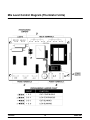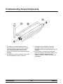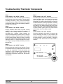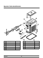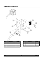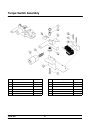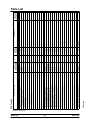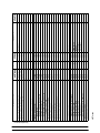
1
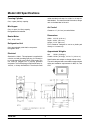
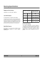
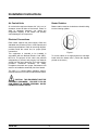
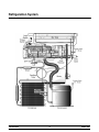
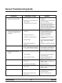
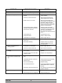
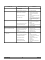
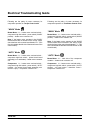
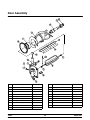
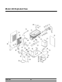
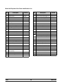
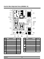
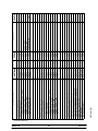
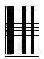
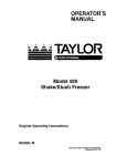
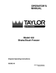
Model 430
Shake/Slush Freezer
Service Manual
051430- S
2/98
Table of Contents
Section 1: Introduction . . . . . . . . . . . . . . . . . . . . . . . . . . . . . . . . . . . . . . . . . . . . . . .
1
Safety . . . . . . . . . . . . . . . . . . . . . . . . . . . . . . . . . . . . . . . . . . . . . . . . . . . . . . . . . . . . .
2
Refrigerant . . . . . . . . . . . . . . . . . . . . . . . . . . . . . . . . . . . . . . . . . . . . . . . . . . . . . . . . .
2
Model 430 Specifications . . . . . . . . . . . . . . . . . . . . . . . . . . . . . . . . . . . . . . . . . . . . .
3
Running Specifications . . . . . . . . . . . . . . . . . . . . . . . . . . . . . . . . . . . . . . . . . . . . . . .
4
Installation Instructions . . . . . . . . . . . . . . . . . . . . . . . . . . . . . . . . . . . . . . . . . . . . . . .
5
Refrigeration System . . . . . . . . . . . . . . . . . . . . . . . . . . . . . . . . . . . . . . . . . . . . . . . .
6
Section 2: Controls . . . . . . . . . . . . . . . . . . . . . . . . . . . . . . . . . . . . . . . . . . . . . . . . . . .
7
Torque Control . . . . . . . . . . . . . . . . . . . . . . . . . . . . . . . . . . . . . . . . . . . . . . . . . . . . . .
8
Thermistor Control . . . . . . . . . . . . . . . . . . . . . . . . . . . . . . . . . . . . . . . . . . . . . . . . . .
10
Thermistor Curve . . . . . . . . . . . . . . . . . . . . . . . . . . . . . . . . . . . . . . . . . . . . . . . . . . .
12
Mix Level Control (Thermistor Units) . . . . . . . . . . . . . . . . . . . . . . . . . . . . . . . . . . .
13
Mix Level Control Diagram (Thermistor Units) . . . . . . . . . . . . . . . . . . . . . . . . . . .
14
Section 3: Troubleshooting . . . . . . . . . . . . . . . . . . . . . . . . . . . . . . . . . . . . . . . . . . .
15
General Troubleshooting Guide . . . . . . . . . . . . . . . . . . . . . . . . . . . . . . . . . . . . . . .
16
Electrical Troubleshooting Guide . . . . . . . . . . . . . . . . . . . . . . . . . . . . . . . . . . . . . .
19
Troubleshooting Torque Components . . . . . . . . . . . . . . . . . . . . . . . . . . . . . . . . . .
20
Troubleshooting Thermistor Components . . . . . . . . . . . . . . . . . . . . . . . . . . . . . .
21
Section 4: Parts . . . . . . . . . . . . . . . . . . . . . . . . . . . . . . . . . . . . . . . . . . . . . . . . . . . . . .
23
Parts Warranty Explanation . . . . . . . . . . . . . . . . . . . . . . . . . . . . . . . . . . . . . . . . . . .
24
Operator Parts Identification . . . . . . . . . . . . . . . . . . . . . . . . . . . . . . . . . . . . . . . . . .
25
Door Assembly . . . . . . . . . . . . . . . . . . . . . . . . . . . . . . . . . . . . . . . . . . . . . . . . . . . . .
26
Model 430
Table of Contents
Table of Contents -- Page 2
Model 430 Exploded View . . . . . . . . . . . . . . . . . . . . . . . . . . . . . . . . . . . . . . . . . . . .
27
Control Box Exploded View (X50663-12) . . . . . . . . . . . . . . . . . . . . . . . . . . . . . . .
29
Draw Switch Assembly . . . . . . . . . . . . . . . . . . . . . . . . . . . . . . . . . . . . . . . . . . . . . . .
30
Torque Switch Assembly . . . . . . . . . . . . . . . . . . . . . . . . . . . . . . . . . . . . . . . . . . . . .
31
Accessories . . . . . . . . . . . . . . . . . . . . . . . . . . . . . . . . . . . . . . . . . . . . . . . . . . . . . . . .
32
Parts List . . . . . . . . . . . . . . . . . . . . . . . . . . . . . . . . . . . . . . . . . . . . . . . . . . . . . . . . . . .
33
Wiring Diagrams . . . . . . . . . . . . . . . . . . . . . . . . . . . . . . . . . . . . . . . . . . . . . . . . . . . .
42
Note: Continuing research results in steady improvements; therefore, information in this
manual is subject to change without notice.
E February, 1998 Taylor
All rights reserved.
051430--S
The word Taylor and the Crown design
are registered trademarks in the United States
of America and certain other countries.
Table of Contents
Taylor Company
750 N. Blackhawk Blvd.
Rockton, IL 61072
Model 430
Section 1: Introduction
Model 430
S
Safety
S
Refrigerant
S
Specifications
S
Running Specifications
S
Installation Instructions
S
Refrigeration System
1
Introduction
Safety
Refrigerant
We at Taylor Company, are committed to
manufacturing safe operating and serviceable
equipment. The many built-in safety features that are
part of all Taylor equipment are aimed at protecting
operators and trained service technicians alike.
This manual is intended exclusively for Taylor
Company authorized service personnel.
Taylor Company uses R404A refrigerant. This
refrigerant is generally considered non-toxic and
non-flammable; however, any gas under pressure is
potentially hazardous.
NEVER fill any refrigerant cylinder completely with
liquid. Filling the cylinder to approximately 80% will
allow for normal expansion.
Stationary appliances which are not equipped
with a power cord and a plug or other device to
disconnect the appliance from the power source must
have an all--pole disconnecting device with a contact
gap of at least 3 mm installed in the external
installation. Failure to follow this instruction may result
in electrocution.
Refrigerant liquid sprayed onto the skin may
cause serious damage to tissue. Keep eyes and skin
protected. If refrigerant burns should occur, flush
immediately with cold water. If burns are severe, apply
ice packs and contact a physician immediately.
The Taylor Company reminds technicians to be
cautious of government laws regarding
refrigerant recovery, recycling, and reclaiming
systems. If you have any questions regarding
these laws, please contact the factory Service
Department.
This machine must be placed on a level
surface. Failure to comply may result in personal injury
or equipment damage.
WARNING: R404A refrigerant used in conjunction
with polyolester oils is extremely moisture absorbent.
When opening a refrigeration system, the maximum
time the system is open must not exceed 15 minutes.
Cap all open tubing to prevent humid air or water from
being absorbed by the oil.
DO NOT install the unit in an area where a
water jet could be used to clean or rinse the freezer.
Failure to follow this instruction may result in serious
electrical shock.
This machine is designed to operate indoors, under
normal ambient temperatures of 70°--75°F
(21°--24°C). The machine has successfully performed
in high ambient temperatures of 104°F (40°C) at
reduced capacities.
NOISE LEVEL: Airborne noise emission does not
exceed 70 dB(A) when measured at a distance of 1.0
meter from the surface of the machine and at a height
of 1.6 meters from the floor.
Introduction
2
Model 430
Model 430 Specifications
Freezing Cylinder
outlet must also be 20 amp. for 115/60/1 or 15 amp. for
208-230/60/1. For exact electrical information, always
refer to the data label of the unit.
One, 4 quart (3.8 liter) capacity.
Mix Hopper
Air Cooled
One, 14 quart (13.2 liter) capacity.
Refrigerated and insulated.
Clearance: 6” (15.2 cm.) around all sides.
Beater Motor
Dimensions
One, .25 hp. motor.
Width: 16-7/16” (41.8 cm.).
Depth: 28-3/4” (73.0 cm.).
Height: 27-1/2” (69.9 cm.).
Floor Clearance: Designed to rest on a plastic pad
directly on a counter top.
Refrigeration Unit
One, approximately 4,000 btu/hr compressor.
Refrigerant 404A.
Approximate Weights
Electrical
Net:
176 lbs. (79.8 kgs.).
Crated: 215 lbs. (97.5 kgs), 14.5 cu. ft. (.40 cu. m.).
Standard is 115/60/1. This equipment is supplied with
a 3-wire cord and grounding type plug, for connection
to a single phase, 60 cycle, branch circuit supply. This
unit must be plugged into a properly grounded
receptacle. The cord and plug provided are 20 amp. for
115/60/1, or 15 amp. 208-230/60/1. Therefore, the wall
Model 430
Specifications are subject to change without notice.
This unit is designed and constructed to meet stringent
safety and sanitation requirements for NSF, UL, and
CSA.
3
Introduction
Running Specifications
Expansion Valve Setting
Ambient Temperature
404A/HP62: 38 - 39 PSI (262 - 268 kPa.).
Low Side Pressure
Low side pressure = expansion valve setting.
To adjust the low side pressure, place the gauge on the
low side suction port at the compressor. With the
compressor running, turn the adjustment knob of the
automatic expansion valve clockwise to raise low side
pressure and counterclockwise to lower pressure.
Normal Operating
Head Pressures
F.
C.
PSI
70_
21.1_
240 - 270
(1,655 - 1,862 kPa.)
80_
26.7_
270 - 300
(1,862 - 2,069 kPa.)
90_
32.2_
300 - 340
(2,069 - 2,344 kPa.)
100_
37.8_
340 - 380
(2,344 - 2,620 kPa.)
E.P.R. Valve Setting
The product temperature in the mix hopper is
maintained by the main refrigeration system and can
be adjusted by the E.P.R. valve. The E.P.R. valve is
factory set at 57 - 59 PSI (393 - 406 kPa.) in order to
maintain hopper product temperature below 40_F.
(4_C.).
High Side Pressure
Air Cooled: The following chart indicates normal
operating head pressures at various ambient
temperatures:
Introduction
4
Model 430
Installation Instructions
Air Cooled Units
Beater Rotation
Air cooled units require a minimum of 6” (15.2 cm.) of
clearance around all sides of the freezer. Failure to
allow for adequate clearance can reduce the
refrigeration capacity of the freezer and possibly
cause damage to the compressor.
Beater rotation must be clockwise as viewed looking
into the freezing cylinder.
Electrical Connections
Each freezer requires one power supply. Check the
data label on the freezer for fuse, circuit ampacity and
electrical specifications. Refer to the wiring diagram,
provided inside the control box, for proper power
connections.
Figure 1.
This equipment is intended to be installed in
accordance with the National Electric Code (NEC),
NFPA 70. The purpose of this code is the practical
safeguarding of persons and property from hazards
arising from the use of electricity. This code contains
provisions considered necessary for safety.
Compliance therewith and proper maintenance will
result in an installation essentially free from hazard.
To correct rotation on a single-phase unit, exchange
leads inside the beater motor. (Follow the diagram
printed on the motor.)
The NEC is a United States regulatory agency.
International users must follow local electrical codes.
CAUTION: THIS EQUIPMENT MUST BE
PROPERLY GROUNDED! FAILURE TO DO SO
CAN RESULT IN SEVERE PERSONAL INJURY
FROM ELECTRICAL SHOCK!
Model 430
5
Introduction
Refrigeration System
Introduction
6
Model 430
Section 2: Controls
S
Torque Control
S
Thermistor Control
S
Thermistor Curve
S
Mix Level Control
S
Mix Level Control Diagram
IMPORTANT: The Model 430 was first manufactured with the Thermistor Control and
is now designed with the Torque Control. The information in this manual covers both
designs.
Model 430
7
Controls
Torque Control
Operation
If the torque sensor returns to the unsatisfied position
during the additional 20 seconds of beater operation,
the compressor will run again for an additional 10
seconds (minimum), and will continue until the torque
sensor is satisfied. The beater motor will run for 20
seconds.
When the unit is placed in the “AUTO” mode, the
beater motor is activated. After a three second delay,
the compressor starts. When the torque sensor
indicates that viscosity has been achieved, it trips a
microswitch, and the compressor stops. The beater
motor continues to run for 20 seconds and then stops.
Controls
If the torque sensor remains in the satisfied position
after a 7 minute cycle time has elapsed, the
refrigeration system will reactivate for 12 seconds, or
until viscosity is satisfied.
8
Model 430
Features
Mix Low
The lockout mode works by use of a magnet. The
magnet has been placed in the upper right hand corner
of the freezer door. Behind the front panel of the
freezer, there is a reed switch. (Door switch on the wire
diagram.) When the freezer door is in place on the
freezer, the magnet holds the reed switch open,
signaling the control that the door is in place. When the
freezer door is removed, the reed switch closes,
signaling the control that the door is not in place. The
control must sense that the reed switch is closed for at
least five minutes and that the power switch is in the
“OFF” position before the lockout is cleared and the
four day timer is reset.
/ Mix Out
The Taylor Model 430 torque control is equipped with
the mix low/mix out function. When the mix supply is
low, the sensor activates the “MIX LOW” light to
indicate a need for mix replenishment.
When a mix out condition is detected, the sensor
activates the “MIX OUT” light. The beater motor and
compressor are disabled at the completion of the draw.
Once the mix supply has been replenished, there is a
30 second delay before the refrigeration system
continues.
Ready Light (Optional)
When the control determines that the product is at a
servable viscosity, the “READY” light on the front panel
illuminates. Servable viscosity is determined in the
following manner.
Protection Fuse
There is an external fuse located on the control board.
(See illustration on page 8.) Although it appears to be
soldered to the board, it is actually plugged into two
small sockets on the board. The fuse protects the
transformer from damage in the event that the
secondary side of the board becomes shorted. When
the fuse is open (blown), all board functions are
interrupted. The fuse must then be replaced.
When the control switch is first placed in the “AUTO”
position, the product must freeze down to the viscosity
set point (until the torque switch is satisfied). Once the
torque switch is satisfied, the “READY” light will
illuminate. During normal draw patterns, the control
monitors how long the draw valve is open to estimate
the amount of product drawn, and the control monitors
how long the compressor has run to estimate the
amount of cooling that has taken place. Within the
software a “Reference Value” has been established to
determine the status of the “READY” light.
Lockout (Optional)
The unit is equipped with an optional lockout mode.
The lockout mode requires that the unit be taken apart
and cleaned every four days. (Taylor recommends,
and most local health code laws demand, daily
cleaning.)
If the unit is not taken apart and cleaned in four days,
the control will enter the lockout mode, and the
cleaning required light will flash. The beater motor and
the compressor are then disabled.
Model 430
Drawing product raises the reference value,
compressor operation lowers it. When the reference
value drops to the pre-determined value, the ready
light illuminates.
9
Controls
Thermistor Control
Function
When the product in the freezing cylinder reaches 2_F.
(1_C.) above the control set-point, the thermistor relay
closes, sending L1 power to the compressor relay coil.
The refrigeration system will run until the control
set-point is achieved.
The thermistor control maintains temperature in the
freezing cylinder by monitoring the resistance of the
thermistor probe.
Specifications
Temperature Differential:
above cut-out.
cut in = 2_F. (1.1_C.)
Anticipator
Coarse Adjustment Range: 10_ to 30_F. (-12_ to
-1_C.).
The anticipator signals the thermistor control to
activate the refrigeration system whenever product is
drawn. As the draw valve is raised (freezer draw switch
closes), continuity is created between the thermistor
control anticipator terminals. The thermistor control
relay will close within 1 second to start the refrigeration
system.
Fine Adjustment Range: 4_F. (2_C.) total.
Coarse Adjustment Potentiometer:
approximately 6_F. (3_C.).
1/4 turn =
Input Voltage Supply: 24 VAC.
Thermistor Probe (Part # 038061-BLK)
The resistance value of the thermistor probe
corresponds with the product temperature in the
freezing cylinder. As the product becomes colder, the
probe resistance increases. As the product becomes
warmer, the probe resistance decreases.
Upon completing the draw, the thermistor control
recognizes the loss of continuity between the
anticipator terminals, but will continue refrigeration for
at least 25 seconds. This allows for additional blending
and freezing of the warmer mix which has entered the
freezing cylinder. After approximately 25 seconds
have elapsed, the thermistor control returns to normal
operation and cycles off the refrigeration system when
the set-point temperature is achieved.
Approximate probe resistance readings:
1.
10,000 ohms at room temperature:
78_F. (25_C.).
2.
46.012 ohms at serving temperature:
20_F. (-6.6_C.).
Operation
Cycle Timer
The thermistor probe is positioned in the bulb-well
located at the front of the freezing cylinder. The
thermistor control becomes operational when
powered by the 24 VAC transformer.
During periods when no product is being dispensed, an
8 minute cycle timer will signal the thermistor control
to activate the refrigeration system. As the timer
cycles, continuity is created between the thermistor
control anticipator terminal. The thermistor control
relay will close within 1 second. The refrigeration
system will then activate.
When the desired product is achieved (control
set--point) the thermistor control relay opens and
discontinues the power sent to the compressor relay
coil.
Controls
10
Model 430
Setting Temperature
1.
Position the thermistor fine adjustment at
mid-range. This will limit the fine adjustment
temperature range to ±2_F. (±1_C.).
2.
Turn the coarse adjustment clockwise to the
coldest setting.
3.
With the freezer correctly primed, place the
power switch in the “AUTO” position.
4.
After the appropriate freezing time, test the
product temperature. When a sample portion
temperature is approximately 1_ above the
desired temperature setting, slowly turn the
coarse adjustment counterclockwise (warmer)
until the refrigeration system cycles off.
5.
ELECTRICAL SHOCK AREA! USE CAUTION!
Allow the refrigeration system to cycle through
at least two “OFF” cycles. After the unit cycles
off, draw a sample of product and check the
temperature. Readjust the coarse adjustment
as required, but make only small adjustments.
1.
Make sure power is being supplied to the
freezer and that all operating switches are in
the correct position.
2.
Using a voltmeter, check the voltage supply to
the thermistor control. The control requires 24
volts to operate.
3.
Using an ohmmeter, check probe resistance.
(Refer to the thermistor curve chart on page 12
for proper readings.)
If the thermistor relay which deactivates the
compressor will not open, check the following items:
Note: The anticipator automatically activates the
refrigeration system 0 - 1 second after the draw valve
is opened. If several small samples are drawn, the
temperature may drift lower. To accurately set the
control, let the product temperature stabilize by
allowing the thermistor control to cycle the freezer on
and off by the control set point instead of the
anticipator.
1.
Make sure the thermistor relay opens when the
freezer control switch is in the “OFF” position.
Service Tips
2.
Make sure the thermistor probe is connected to
the correct probe terminals.
If a problem arises with the thermistor control
assembly, identify and replace only the faulty
component. For example, if the probe is defective,
replace only the probe.
3.
Using an ohmmeter, check the thermistor probe
for proper resistance. (Refer to the thermistor
curve chart on page 12 for proper readings.)
A varistor must be connected to the thermistor
control’s 24 VAC terminals in order to protect the
control from voltage spikes (varistor part number
X31547).
4.
Disconnect one wire to an anticipator terminal.
If the thermistor relay opens after
approximately 25 seconds, the problem is in the
anticipator wiring circuit.
ELECTRICAL SHOCK AREA! USE CAUTION!
Fill the bulb-well with automotive antifreeze before
installing the thermistor probe, and be sure the probe
is installed completely into the bottom of the bulb-well.
When problems such as erratic product quality occur,
it is of utmost importance to determine if the thermistor
components are defective before replacing them.
Note: Lower the probe to the point where the wires
extend from the probe and a resistance is felt. This
indicates the probe is installed completely in the
bottom of the bulb-well.
For a diagram of the thermistor control, see
page 21
(Troubleshooting
Thermistor
Components).
If the thermistor relay which starts the compressor will
not close, check the following items:
Model 430
11
Controls
Thermistor Curve
F.
C.
-10
-23.3
-9
K OHM
F.
C.
118.201
22
-5.5
-22.7
114.394
23
-8
-22.2
110.709
-7
-21.6
-6
-21.1
-5
-20.5
F.
C.
43.530
54
12.2
17.915
-5.0
42.340
55
12.7
17.451
24
-4.4
41.136
56
13.3
16.998
107.143
25
-3.8
39.967
57
13.8
16.557
103.692
26
-3.3
38.830
58
14.4
16.128
27
-2.7
37.727
59
15.0
15.710
-4
-20.0
97.120
28
-2.2
36.654
60
15.5
15.315
-3
-19.4
94.085
29
-1.6
35.612
61
16.1
14.929
-2
-18.8
91.144
30
-1.1
34.599
62
16.6
14.554
-1
-18.3
88.296
31
-0.5
33.616
63
17.2
14.187
0
-17.7
85.536
32
0
32.660
64
17.7
13.830
1
-17.2
82.863
33
0.5
31.760
65
18.3
13.482
2
-16.6
80.273
34
1.1
30.885
66
18.8
13.143
3
-16.1
77.765
35
1.6
30.035
67
19.4
12.812
4
-15.5
75.334
36
2.2
29.207
68
20.0
12.490
5
-15.0
72.980
37
2.7
28.403
69
20.5
12.185
6
-14.4
70.627
38
3.3
27.620
70
21.1
11.888
7
-13.8
68.350
39
3.8
26.859
71
21.6
11.598
8
-13.3
66.147
40
4.4
26.120
72
22.2
11.315
9
-12.7
64.014
41
5.0
25.400
73
22.7
11.039
10
-12.2
61.951
42
5.5
24.721
74
23.3
10.769
11
-11.6
59.953
43
6.1
24.059
75
23.8
10.507
12
-11.1
58.021
44
6.6
23.416
76
24.4
10.250
13
-10.5
56.150
45
7.2
22.789
77
25.0
10.000
14
-10.0
54.340
46
7.7
22.180
78
25.5
9.763
15
-9.4
52.854
47
8.3
21.586
79
26.1
9.532
16
-8.8
51.409
48
8.8
21.009
80
26.6
9.306
17
-8.3
50.003
49
9.4
20.447
81
27.2
9.085
18
-7.7
48.636
50
10.0
19.900
82
27.7
8.870
19
-7.2
47.306
51
10.5
19.384
83
28.3
8.659
20
-6.6
46.012
52
11.1
18.881
84
28.8
8.454
21
-6.1
44.754
53
11.6
18.392
85
29.4
8.254
100.352
K OHM
K OHM
When checking a thermistor probe, first determine the temperature at the probe and find it on this chart, along with
the correct ohmmeter reading. If your ohmmeter reading varies from the correct reading, determine whether the
difference is acceptable. If a probe is faulty, the difference will be great.
Controls
12
Model 430
Mix Level Control (Thermistor Units)
The mix level control (P/N X41420) may be used in
both 115 volt and 208-240 volt applications. The
control has a switch (labeled SW4) that may be
changed to 240 volt or 115 volt by placing the switch
in the desired position. (See item “A” on page 14.)
The following shows the position of the switch in the
three possible situations:
1.
No power to the control.
2.
Power to the control and no continuity
between the terminals.
3.
Power to the control and continuity between
“COM” and “OUT” terminals.
Note: The factory default is 240 volts.
CAUTION: If 115 volts are connected to the control
and SW4 is in the 240 volt position, the control will not
respond to the mix out condition. If 208-240 volts are
connected to the control and the SW4 switch is in the
115 volts position, severe damage to the control will
take place.
The power hook-ups are located on the side of the
control. For proper connection, the terminals are
labeled “L1” and “L2”. (See item “B” on the mix level
control diagram on page 14.)
Probe terminals are labeled “COM”, “LOW”, and
“OUT”. (See item “C” on the mix level control diagram
on page 14.)
L1 output terminals are labeled “MIX LOW”, and “MIX
OUT”. Power supplied to the terminal labeled “L1” is
present at the “MIX OUT” terminal when no continuity
is established between the “COM” and “OUT”
terminals. Power supplied to the terminal labeled “L1”
is present at the “MIX LOW” terminal when no
continuity is established between the “COM” and
“LOW” terminals. When continuity of at least 2K ohms
resistance is established between the “COM” and
“OUT” terminals, L1 power will no longer be present at
the “MIX OUT” terminal.
On the mix level control board, there is a block of six
pins (item E on the control diagram). This block
(labeled J1) is used to allow the L1 power present at
the MIX OUT/LOW terminals to stay constant or pulse.
(When the power is constant the “MIX OUT/LOW”
LED’s will be lit; when the power pulses, the LED’s will
flash.)
When continuity of at least 2K ohms resistance is
established between the “COM” and “LOW” terminals,
L1 power will no longer be present at the “MIX LOW”
terminal. (See item D on the mix level control diagram
on page 14.)
At the Taylor factory, pins 3 & 5 and 4 & 6 on the J1
terminal are jumped together to create the pulse of
power. If pins 1 & 3 or 2 & 4 are jumped together, the
power would remain constant. Randomly jumping
other pins on the J1 terminal may cause damage.
There are two single pole double throw relays on the
control. This means there are two sets of three
terminals, and the center terminal of each set is the
common terminal. Only the “MIX OUT” relay is used in
the 430 application.
Model 430
Note: Terminals 1, 3, and 5 are used for the “MIX
OUT” feature. Terminals 2, 4, and 6 are used for the
“MIX LOW” feature.
13
Controls
Mix Level Control Diagram (Thermistor Units)
Controls
14
Model 430
Section 3: Troubleshooting
Model 430
S
General Troubleshooting Guide
S
Electrical Troubleshooting Guide
S
Troubleshooting Torque Components
S
Troubleshooting Thermistor Components
15
Troubleshooting
General Troubleshooting Guide
PROBLEM
1. No freezer operation with power
switch in the “AUTO” position.
PROBABLE CAUSE
REMEDY
a. Unit unplugged.
a. Plug main power cord in the wall
receptacle.
b. Fuse blown or circuit breaker in the
“OFF” position.
b. Replace the fuse or place breaker
in the “ON” position.
c. The beater motor is out on reset.
c. Place the control switch in the
“OFF” position and press the reset
button firmly. Place the power
switch in the “WASH” position and
observe the freezer’s performance.
Resume normal operation.
a. Tripped internal overload in the
compressor.
a. Allow the internal overload to cool.
Check for high head pressure,
refrigerant overcharge, stuck
pistons, or tight bearings.
b. Compressor is burned out.
b. Replace the compressor.
c. Compressor is improperly wired.
c. Check wiring against diagram on
compressor.
d. Low line voltage.
d. Check the line voltage at terminal
block. Locate cause of voltage
drop.
e. Single-phasing compressor
contactor.
e. Replace the compressor contactor.
3. Unit short cycles.
a. Cycling on high pressure cut-out.
Cut in: 404A: 340 PSI (2,344 kPa.)
Cut out: 404A: 440 PSI (3,034 kPa.)
a. Check the water supply (watercooled units only), and make sure
the condenser is clean. Check for
potential refrigerant overcharge.
4. Compressor hums intermittently,
but will not start. Cycling on
overload.
a. Compressor is improperly wired.
a. Check wiring against the diagram.
b. Low line voltage.
b. Check the main line voltage, and
locate voltage drop.
c. Relay contacts not closing.
c. Check by operating manually.
Replace defective relay.
a. Temperature or viscosity control is
set too cold.
a. See the “Thermistor Control” or
PCB A. section in this manual to
reset the control.
b. Inadequate mix in the hopper.
b. Fill hopper with mix.
6. Product too soft.
a. Temperature or viscosity control is
set too warm.
a. See the “Thermistor Control” or
PCB A. section in this manual to
reset the control.
7. Head pressure too low.
a. Shortage of refrigerant.
a. Locate and repair leak. Recover
the refrigerant, evacuate, and
charge the system.
b. Water valve stuck open (water
cooled unit).
b. Clear, or replace the valve.
2. With the power switch in the
“AUTO” position, the beater motor
runs, but the compressor does
not operate.
5. Product too stiff.
Troubleshooting
16
Model 430
PROBLEM
PROBABLE CAUSE
REMEDY
8. Hot liquid line.
a. Shortage of refrigerant.
a. Repair leak and recharge system.
9. Frosted liquid line.
a. Restricted dryer or tubing.
a. Replace or remove restrictions.
10. No product being dispensed.
a. Control switch is in the “OFF”
position.
a. Place the control switch in the
“AUTO” position.
b. Freeze-up in the mix feed tube.
b. Adjust hopper temperature by
readjusting the E.P.R. pressure.
c. Beater motor is out on reset.
c. Place the control switch in the
“OFF” position, and press the reset
button firmly. Place the power
switch in the “WASH” position and
observe the freezer’s performance.
Resume normal operation.
d. Incorrect beater rotation. (Rotation
should be clockwise when viewed
from the front of the unit.)
d. Reverse any two of the three
incoming power lines (three phase
units only). For single phase units,
the motor must be rewired
according to the instructions on the
motor.
e. Circuit breaker out.
e. Check breaker or fuse.
f.
f.
11. Scored freezing cylinder walls.
12. Product not feeding into the
freezing cylinder.
13. Drive shaft stuck in the drive
coupling.
14. Excessive mix leakage through
the rear of the unit into the drip
pan.
15. Beater assembly works forward.
Faulty draw switch.
Repair or replace switch.
g. Inadequate mix in the hopper.
g. Fill the hopper with mix.
a. Missing or worn front bearing on the
freezer door.
a. Install or replace front bearing.
b. Bent beater assembly.
b. Replace beater and correct the
cause of insufficient mix in the
freezing cylinder.
a. Inadequate mix in the hopper.
a. Fill the hopper with mix.
b. Freeze-up in the mix inlet hole.
b. Adjust hopper temperature.
a. Mix and lubricant collected in the
drive coupling.
a. Brush clean rear shell bearing area
regularly.
b. Rounded corners of the drive shaft,
coupling, or both.
b. Replace worn component(s).
a. Worn or missing drive shaft boot
seal.
a. Replace boot seal.
b. Inadequate lubrication of the drive
shaft boot seal.
b. Lubricate the boot seal according
to the Operator’s Manual.
c. Worn rear shell bearing.
c. Replace bearing.
d. Drive shaft works forward.
d. Check gear alignment and scraper
blades. Make sure the beater is
not bent.
e. Wrong type of lubricant being used.
e. Use lubricants recommended in the
Operator’s Manual.
a. Refrigerant shortage.
a. Locate and repair leak.
b. Rear bearing unit is out of alignment. b. Align rear bearing unit.
Model 430
17
Troubleshooting
PROBLEM
16. Freezer door works loose.
PROBABLE CAUSE
REMEDY
a. Handscrews are not tightly installed
or are damaged.
a. Tighten or replace handscrews.
b. Beater assembly works forward.
b. See previous problem.
a. Bad scraper blades.
a. Replace blades.
b. Mix feed tube is not installed.
b. Install feed tube according to
instructions in the Operator’s
Manual.
c. Beater rotates continually.
c. Check for electrical short or faulty
power switch.
d. Long “ON” cycles.
d. Make sure there is sufficient mix in
the hopper and that the condenser
is clean. Check the refrigerant
charge.
a. Improper lubrication.
a. Lubricate the draw valve according
to instructions in the Operator’s
Manual.
b. Worn or nicked o-rings on valve.
b. Replace o-rings.
c. Wrong lubricant being used.
c. Use lubricants recommended in the
Operator’s Manual.
19. Mix in the hopper is too cold.
a. Temperature is out of adjustment.
a. Adjust E.P.R. valve.
20. Mix in the hopper is too warm.
a. Temperature is out of adjustment.
a. Adjust E.P.R. valve.
b. Warm mix has been put in the
hopper.
b. Mix added to the hopper should be
below 40_F. (4_C.)
c. Hopper cover not in position.
c. Install cover properly.
a. Low refrigerant charge.
a. Locate and repair the refrigerant
leak.
b. Worn or missing scraper blades.
b. Replace scraper blades.
c. Inadequate air clearance.
c. Provide 6” (15.2 cm.) around all
sides of the unit.
d. Incorrect beater rotation.
d. Rotation should be counterclockwise.
e. Faulty expansion valve.
e. Replace valve.
f.
f.
17. Low overrun.
18. Leaking draw valve.
21. Compressor runs too long or
continuously.
Troubleshooting
Dirty or faulty fan assembly.
18
Clean, repair or replace the fan
assembly.
Model 430
Electrical Troubleshooting Guide
Following are the paths of power necessary for
component operation on Torque Control units.
Following are the paths of power necessary for
component operation on Thermistor Control units.
“WASH” Mode
“WASH” Mode
Beater Motor: L1 -- beater motor overload switch -compressor high limit switch -- power switch (“WASH”
position) -- beater motor contactor coil.
Beater Motor: L1 -- beater motor overload switch -compressor high limit switch -- power switch (“WASH”
position) -- beater motor contactor coil.
Note: If the beater motor operates in the “WASH”
mode but there are no functions in the “AUTO” mode,
check the fuse on the control board labeled “F1.” (This
fuse is located at the left side of the transformer on the
control board.)
Note: If the beater motor operates in the “WASH”
mode but there are no functions in the “AUTO” mode,
check the fuse on the control board labeled “F1.” (This
fuse is located at the left side of the transformer on the
control board.)
“AUTO” Mode
Beater Motor: L1 -- beater motor overload switch -compressor high limit switch -- printed circuit board
assembly (com. and beater) -- beater motor contactor
coil.
“AUTO” Mode
Compressor: L1 -- beater motor overload switch -compressor high limit switch -- power switch ( “AUTO”
position) -- the printed circuit board assembly (com.
and N.O. cprsr) -- compressor contactor coil.
Compressor: L1 -- beater motor overload switch -compressor high limit switch -- power switch ( “AUTO”
position) -- mix level control -- thermistor control -compressor contactor coil.
Model 430
Beater Motor: L1 -- load side of the compressor
contactor -- beater motor contactor coil.
19
Troubleshooting
Troubleshooting Torque Components
C. If incorrectly sized, damaged or improperly
lubricated o-rings are used, the rotor, door,
torque arm, torque rotor and torque lever may be
damaged.
D. If the torque arm is missing, the product will
freeze and the pulley belt will begin slipping. The
beater reset will then deactivate freezer
operation. In addition, torque components may
be damaged.
A. A missing or worn guide bearing will cause
uneven movement of the rotor system, and will
result in product inconsistencies (too stiff/too
thin). If product becomes too stiff, the door,
torque arm, torque rotor and torque lever may be
damaged.
B. Any distortion or incorrect assembly of the torque
rotor will damage the torque components.
Troubleshooting
20
Model 430
Troubleshooting Thermistor Components
Step 1
Power Switch in the “AUTO” Position
Step 4
Power Switch in the “OFF” Position
Check the probe resistance. Disconnect both the white
(yellow) and black wires at the control, and measure
their resistance with an ohmmeter. At room
temperature, a reading of approximately 10,000 ohms
should be obtained. At serving temperature, a reading
of approximately 46,000 ohms should be obtained. If
this reading is not obtained, replace the probe. When
replacing the probe, fill the bulb-well with antifreeze.
Connect the white (yellow) wire to the white terminal
and the black wire to the black terminal.
Using a voltmeter, check the two terminals connecting
the transformer wires to the controller. There should be
a reading of 24 volts (±15%); if not, the transformer
is not receiving line voltage or the transformer is faulty
and should be replaced. If a proper reading is obtained,
proceed to the next step.
Step 2
Power Switch in the “AUTO” Position
Using a voltmeter, make certain L1 power is being
supplied to the common terminal of the controller. A
reading of line voltage should be obtained. To
accomplish this, measure voltage between the
common terminal and any L2 power source. If a proper
reading is not obtained, make sure there is line voltage
at the incoming power supply. If there is incoming
power, back track from the common terminal (L1) and
determine where L1 is being interrupted and correct
accordingly. If a proper reading is obtained, proceed to
the next step.
Step 5
Power Switch in the “OFF” Position
Check the anticipator microswitch by removing the
wires connecting the switch to the controller, and
check for continuity. If switch continuity exists when
the draw handle is raised, the switch is effective.
Continuity should break when the draw handle is
lowered.
Step 3
Power Switch in the “AUTO” Position
Remove the probe wires from the controller. Place a
wire between the two probe terminals of the controller
to short the component. This should activate the
compressor. If this procedure does not activate the
compressor, check for line voltage. If there is line
voltage at the compressor contactor coil, the controller
is acceptable.
Model 430
21
Troubleshooting
Notes:
Troubleshooting
22
Model 430
Section 4: Parts
Model 430
S
Parts Warranty Explanation
S
Operator Parts Identification
S
Exploded Views
S
Complete Parts List
S
Wiring Diagrams
23
Parts
Parts Warranty Explanation
Class 103 Parts:
Warranty is extended 1 year from the original date of
freezer installation.
Class 000 Parts:
Wear Items - no warranty.
Beater Motor:
Warranty is extended two years from the original date of
freezer installation.
Freezing Cylinder:
This item is covered five years from the original date of
installation.
Compressor:
This item is covered five years from the original date of
installation.
CAUTION: Warranty is valid only if required service work is provided by an Authorized Taylor Service
Technician.
NOTE: Taylor reserves the right to deny warranty claims on equipment or parts if a non--approved
refrigerant was installed in the machine, system modifications were performed beyond factory
recommendations, or it is determined that the failure was caused by neglect or abuse.
Compressor Warranty Disclaimer
The refrigeration compressor on this machine is
warranted for the term indicated on the warranty card
accompanying this machine. However, due to the
Montreal Protocol and the U.S. Clean Air Act
Amendments of 1990, many new refrigerants are
being tested and developed; thus seeking their way
into the service industry. Some of these new
refrigerants are being advertised as drop-in
replacements for numerous applications. It should be
noted that, in the event of ordinary service to this
machine’s refrigeration system, only the refrigerant
specified on the affixed data label should be used. The
unauthorized use of alternate refrigerants will void
your compressor warranty. It will be the owners’
responsibility to make this fact known to any
technicians they employ.
Parts
It should be noted, that Taylor does not warrant the
refrigerant used in its equipment. For example, if the
refrigerant is lost during the course of ordinary service
to this machine, Taylor has no obligation to either
supply or provide its replacement either at billable or
unbillable terms. Taylor does have the obligation to
recommend a suitable replacement if the original
refrigerant is banned, obsoleted, or no longer available
during the five year warranty of the compressor.
The Taylor Company will continue to monitor the
industry and test new alternates as they are being
developed. Should a new alternate prove, through our
testing, that it would be accepted as a drop-in
replacement, then the above disclaimer would
become null and void. To find out the current status of
an alternate refrigerant as it relates to your
compressor, call the local Taylor Distributor or the
Taylor Factory. Be prepared to provide the
model/serial number of the unit in question.
24
Model 430
Operator Parts Identification
Item
Description
Part Number
1
Shield-Splash
049320
2
Tray-Drip
3
Pan-Drip 17-1/4 Long
4
Item
Description
Part Number
8
Tube-Feed 13/32 Hole
025663-10
049319
9
Cover A.-Black Insulated
X49679-BLA
027504
10
Panel-Back
049325
Gasket-Base Pan
049420
11
Panel-Side Right
049640
5
Panel A.-Front
X50678
12
Screw-Panel 10-32 x 3/8
024298
6
Stud-Nose Cone
013496
13
Washer-Freezer Stud
049032
7
Panel-Side Left
049639
Model 430
25
Parts
Door Assembly
Item
Description
Part Number
Item
Description
Part Number
1
Door A.-Partial
X39248
11
Bearing-Front
013116
2
Handle A.-Draw
X47384
12
Beater A.-4 Qt. 1 Pin Support
X49490
3
Valve-Draw
047734
13
Blade-Scraper-Plastic
046237
4
Valve A.-Handle Pin
X25929
14
Clip-Scraper Blade
046238
5
O-Ring - 1 OD x .139 W
032504
15
Shaft-Beater
035418
6
Buster-Ice
047735
16
Seal-Drive Shaft
032560
7
O-Ring - .291 ID x .080 W
018550
17
O-Ring 7/8 OD x .139 W
025307
8
Torque Assembly
X50382
18
Arm-Torque
025660
9
Bearing-Guide
014496
19
Nut-Stud
029880
Gasket-Door 5.109 ID x 5.630
014030
10
Parts
26
Model 430
Model 430 Exploded View
Model 430
27
Parts
Model 430 Exploded View Parts Identification List
Item
Description
Part No.
Item
Description
Part No.
1
Belt-V 4L350
004194
23
Dryer-Filter 1/4 x 1/4 Solder
048878
2
Pulley-AK-49
051394
24
Switch A.-Torque (See page 31.)
X50895-SER
3
Screw-5/16-18 x 5/8 MF Hex Cap
017326
25
Switch-Draw (See page 30.)
N/A
4
Gear A.-Reducer
015985
26
Light-Add Mix-Amber 12 VDC
047141-02
5
Shell A.-Insulated
X50392
27
Light-Mix Out-Amber 12 VAC
047142-02
5a Bearing-Rear Shell-Plastic
032511
28
Panel A.-Front
X50678
5b Guide-Drip Seal
028992
29
Switch-Rocker Auto/Wash
048420
5c
028991
30
Frame Assembly
N/A
Nut-Brass Bearing
5d O-Ring - 1-1/16 OD x .070 Wall
018432
*30a
Pan-Base
049329
6
Disc-Probe (Square Hole)
030965
*30b
Support-Shell Front
049330
7
Probe A.-Mix Low-HT
X42077
*30c
Support-Shell Rear
049331
8
Spacer-Probe (Square Hole)
030966
31
Pulley-AK27-1/2
016190
9
Washer-#10 Shakeproof
002681
32
Motor-1/4 HP
014477-
10
Nut-10-32 Hex
005598
Cord-Power 125V (115 Volt)
085093
33
11
Valve-EPR 1/4 S
022665
Cord-Power (208-230 Volt)
025340-27
12
Panel-Back
049325
34
Compressor
049302-
13
Cover-Control Box
049321
35
Nut-5/16-18 MF Lock
017327
14
Control A. (See page 29.)
X50663-12
36
Washer-3/8 Flat ZP Steel
000653
15
Valve-Exp-Auto 1/4 S x 1/4 FPT
047232
37
Sleeve-Mounting-Compressor
039920
16
Guide A.-Drip Pan
X49327
38
Grommet-Compressor Mount
039919
17
Motor-Fan 50 Watt
029770-
39
Screw-5/16-18 x 1-1/2 Hex Cap
001894
18
Fan-5 Blade 12
049009
40
Support-Drip Tray
049318
19
Shroud-Fan
048877
41
Stud-Nose Cone 5/16-18 x 5/16
013496
20
Condenser-AC 12 L x 16 H x
2.5 T (3 Row)
048935
42
Washer-Freezer Stud
049032
Panel-Side Left
049639
43
Probe A.-Mix Out - Square Hole
X41348
Panel-Side Right
049640
*44
Switch-Pressure 440 PSI
048230
Screw-10-32 x 3/8 Truss Hd SS
024298
*45
Tube-Capillary
051049
21
*21a
22
Parts
*Not Shown
28
Model 430
Control Box Exploded View (X50663-12)
Item
Description
Part No.
Item
Description
Part No.
1
PCB A.-Control *430 Torque
X50385-SER
13
Screw 8-32 x 5/16 Bind. Hd
008399
2
Block-Terminal-Plug 7 P
040322-003
14
Block-Terminal 7 Pole Green
024156
3
Block-Terminal-Plug 8 P
040322-004
15
Screw 8 x 1/2 Pan Hd.
017986
4
Standoff-Nylon 6-32 x 3/8 L
040280-008
16
Label-Grounding Symbol
017669
5
Screw- 6-32 x 3/8 Bin. Hd
002201
Capacitor-Start (115 Volt)
039557-27
6
Box-Control *430*
049317
Capacitor-Start (230 Volt)
039567
Capacitor-Run (115 Volt)
023739
Capacitor-Run (230 Volt)
027087
7
Starter-1 Phase 3 to 5 Amp
041950-
8
Screw-8 x 1/4 SL Hex Hd
009894
9
17
18
Bushing-Split 43/64 ID x 7/8 OD
027691
19
Strap-Capacitor 6-5/8 In.
037890
10
Plug-Hole 7/8 Dia.
010077
20
Relay-3 Pole 115 V
012725-
11
Filter-Corcom 2VR1
032567
21
Plug-Hole 3/4 Dia. Black Nylon
078018
Relay-Start-Compressor (115 V)
045432-12
Relay-Start-Compressor (230 V)
048150
12
Model 430
29
Parts
Draw Switch Assembly
Item
Description
Part No.
Item
Description
Part No.
1
Bracket A.-Draw Switch
X50497
5
Screw 4-40 x 5/8 RHM
027219
2
Arm A.-Draw Valve *430* Torque
X50389
6
Switch-Lever-SPDT 10A-125-25
028889
3
Pin-Pivot
015478
7
Plate-Draw Switch
043527
4
E-Ring 3/16 .335 OD
049178
Parts
30
Model 430
Torque Switch Assembly
Item
Description
Part No.
Item
Description
Part No.
1
Nut-10-32 MF Lock
020983
7
Screw-10-32 x 1 RHM ZP Steel
004455
2
Bushing-Pivot-Torque Arm
049739
8
Spring-Torque (White)
050901
3
Nut-Push On
051288
9
Bushing A.-Torque
X50399-SER
4
Arm-Torque Switch
051325
10
Switch-Snap-SPDT 20A/125-250
014472
5
Bushing-Arm-Torque
049737
11
Insulator-Armite-4 Hole
012992
6
Bracket-Torque Control
050400
12
Screw-6-32 x 79 Taptite Rd. Hd.
042514
Model 430
31
Parts
Accessories
Item
Description
Part Number
Item
Description
Part Number
1
Brush-3 x 7 White
023316
4
Brush-Rear Bearing
013071
2
Brush-Double Ended
013072
5
Lubricant-Taylor
047518
3
Brush-Draw Valve
014753
*6
Video-Training M430 Torque
050987-V
*Not Shown
Parts
32
Model 430
Model 430
33
013071
045079
049302--12
BRUSH--REAR BRG 1IN.DX2IN.LGX14
BRUSH--SYRUP PORT
COMPRESSOR AKA9462ZXA--AK172AT
+ Available Separately
Parts List
039567
048150
048935
085093
+CAPACITOR--START-- 72--88UF/330V
+RELAY--START--COMPRESSOR
CONDENSER--AC--12LX16HX2.5T3ROW
CORD--POWER--125V NEMA 5-20 P - 6’ L
430 Torque
027087
+CAPACITOR--RUN-- 15UF/370V
049302--27
023316
BRUSH--MIX PUMP BODY--3”X7”WHITE
COMPRESSOR AKA9462ZXD--AK172ET
014753
BRUSH--DRAW VALVE 1--1/2”OD X 3”
045432--12
013072
BRUSH--DOUBLE ENDED--PUMP&FEED T
039557--27
040322--004
BLOCK--TERMINAL--PLUG 8P .2 SIP
+RELAY--START--COMPRESSOR
040322--003
BLOCK--TERMINAL--PLUG 7P .2 SIP
+CAPACITOR--START-- 72--88UF/250V
024156
BLOCK--TERMINAL--7 POLE GREEN
023739
004194
BELT--V--4L350
+CAPACITOR--RUN-- 25UF/370VAC
004227
046238
+CLIP--SCRAPER BLADE*8.75 INCH*
BELT--V--4L370
046237
X49490
+BLADE--SCRAPER--PLASTIC 9--13/16L
1
012864
+WASHER--BEARING LOCK
BEATER A.--4QT--1 PIN--SUPPORT
1
1
1
1
1
1
1
1
1
1
1
1
1
1
1
1
1
1
1
1
1
1
1
1
028991
1
1
1
+NUT--BRASS BEARING
032511
BEARING--REAR SHELL *PLASTIC*
028992
014496
BEARING--GUIDE
1
1
1
1
QTY.
+GUIDE--DRIP SEAL
013116
BEARING--FRONT
049030
025660
+BUSHING--ARM--TORQUE
ARM--TORQUE *450*350--1 HD SLUSH
PART
NUMBER
047062
DESCRIPTION
ACCUMULATOR--COPPER 2”DIA 10”LG
430 Torque
103
103
103
103
103
512
103
103
103
512
000
000
000
000
000
103
103
103
000
000
103
000
103
000
000
000
000
000
000
103
103
103
WARR.
CLASS
115/60/1
208-230/60/1
208-230/60/1
208-230/60/1
208-230/60/1
115/60/1
115/60/1
115/60/1
115/60/1
J7050000/Up (Replaces 003845)
Prior to J7050000
REMARKS
118
116
PARTS
UPDATE
Parts List
+ Available Separately
Parts List
34
Model 430
X39248
DOOR A.--PARTIAL *430*
049031
015985
X49327
X39969
013116
014496
014030
032504
018550
025307
032560
048260
GASKET--FRONT PANEL
GEAR A.*REDUCER
GUIDE A.--DRIP PAN *430*
KIT A.--TUNE UP* 430
BEARING--FRONT
BEARING--GUIDE
GASKET--DOOR 5.109”ID X 5.630OD
O--RING 1 ’OD X .139W
O--RING--.291 ID X .080W
O--RING--7/8 OD X .139W
SEAL--DRIVE SHAFT
TOOL--CLEANING 0--RING REMOVAL
430 Torque
024315
014030
GASKET--DOOR 5.109”ID X 5.630OD
032749
049420
GASKET--BASE PAN *430*
LABEL--MOVING PARTS WARN
032567
FILTER--CORCOM 2VR1
LABEL--DOOR CAUTION
013739
048878
032504
EYELET--RESET BUTTON
DRYER--FILTER 1/4 X 1/4 SOLDER
+O--RING--1”OD X .139W
047734
050367--
DIAGRAM--WIRING*430*TORQUE
X25929
038374
DECAL--TROUBLESHOOTING
+VALVE--DRAW *SLUSH* ICE BUSTER
050685
DECAL--DEC-- 430 -- TORQUE
+VALVE A.--HANDLE PIN
019029
DECAL--CLEAN INST.--HOPPER
X47384
039992
DECAL--CAUTION--GRD--CIRCUIT
+HANDLE A.--DRAW--SLUSH--BLACK
050499
COVER--HOLE--DRAW HANDLE *430*
047735
X49679--BLA
COVER A.--BLACK INS.MIX HOPPER
+BUSTER--ICE
025340--27
PART
NUMBER
CORD--POWER--230V 15A PLUG--75”L
DESCRIPTION
3
1
1
1
1
1
2
1
1
1
1
1
1
1
1
1
1
1
1
2
1
1
1
1
1
1
1
1
1
1
1
1
1
QTY.
000
000
000
000
000
000
000
000
000
000
000
103
212
000
000
000
103
000
000
000
103
103
103
103
103
000
000
000
000
000
103
103
103
WARR.
CLASS
DRIVE SHAFT
DRIVE SHAFT
TORQUE
DRAW VALVE
TORQUE
208-230/60/1
REMARKS
PARTS
UPDATE
+ Available Separately
Model 430
35
Parts List
047142--02
X49495
LIGHT--MIX OUT--AMBER--RECT.
LINE A.--LIQUID *430*
014477-029770--
MOTOR--1/4 HP
MOTOR--FAN 50 WATT
016190
007538
051394
012725-041082
035418
PULLEY--AK27--1/2
PULLEY--AK64-5/8
PULLEY--AK49
RELAY--3 POLE
SANITIZER KAY--5 125 PACKETS
SHAFT--BEATER *341--2 RFB*
430 Torque
013997
030966
PULLEY--AK23--1/2
030965
X41348
PROBE A.--MIX OUT--SQUARE HOLE
+SPACER--PROBE *SQ HOLE*
X42077
+DISC--PROBE *SQ HOLE*
049775
PROBE A.--MIX LOW--HT
X50207--SER
PCB A.--CONTROL *430*
PLUG--HOLE 1/2
X40868
X50385--SER
PCB A.--CONTROL *430 TORQUE
CHIP--SOFTWARE 430 TORQUE CTRL
049640
PANEL--SIDE RIGHT
X50678
PANEL--A.--FRONT
049639
027504
PAN--DRIP 17--1/4”LONG
PANEL--SIDE LEFT
050363
PAIL--MIX 10 QT.--LABELED
049325
023348
PAIL--MIX 6 QT.
PANEL--REAR
029880
NUT--STUD *340--342--344--350--450*
049009
051430-M
MANUAL-OPERATOR
+FAN--5 BLADE 12” PUSH 22DEG CCW
047518
LUBRICANT--TAYLOR 4 OZ.
051049
047141--02
LIGHT--ADD MIX--AMBER--RECTANGULR
TUBE--CAP..036IDX.087OD X 9 FT.
036529
PART
NUMBER
LABEL--WARNING PANEL
DESCRIPTION
1
1
1
1
1
1
1
2
2
1
1
1
1
1
1
1
1
1
1
1
1
1
4
1
1
1
1
1
1
1
1
1
3
QTY.
103
000
103
103
103
103
103
103
103
103
103
103
212
103
212
103
103
103
103
103
000
000
103
103
103
212
000
000
103
103
103
103
000
WARR.
CLASS
Gear (J7050000/Up)
Gear (Prior to J7050000)
Beater Motor (J7050000/Up)
Beater Motor (Prior to J7050000)
Mix Out
Mix Low
For X50399-SER Bushing (Replaces 034878)
Base Board
Version 114 -- J7043493/Up
Right
Left
Tee w/Capillary Tube
REMARKS
116
116
116
116
PARTS
UPDATE
+ Available Separately
Parts List
36
Model 430
048877
041950--12J
041950--27H
SHROUD--FAN *142*
STARTER--1 PHASE--3 TO 5 AMP
STARTER--1 PHASE--2 TO 3.3 AMP
049178
015478
043527
+E--RING 3/16 .335 O.D.
+PIN--PIVOT
+PLATE--DRAW SWITCH *452 HT*
049739
051288
050455
050901
014472
BUSHING--PIVOT--TORQUE ARM
NUT-PUSH ON -- 9/16 DIAMETER SHAFT
SPRING--TORQUE*PURPLE*
SPRING--TORQUE*WHITE*
SWITCH--SNAP--SPDT--20A/125--250V
430 Torque
TRAY--DRIP *430*
+O--RING--.291 ID X .080W
TORQUE A. *430*
+SEAL--PANEL--ROCKER SWITCH
049319
018550
X50382
048421
048420
049737
BUSHING--ARM--TORQUE
SWITCH--ROCKER AUTO/WASH
X50399--SER
BUSHING A.--TORQUE
048230
050400
SWITCH--PRESSURE 440 PSI--SOLDER
051325
BRACKET--TORQUE CONTROL
X50895--SER
ARM--TORQUE SWITCH
SWITCH A.--TORQUE *430*
028889
X50497
+BRACKET A.--DRAW SWITCH *430*
+SWITCH--LEVER--SPDT--10A--125--250V
X50389
+ARM A.--DRAW VALVE*430*TORQUE
SWITCH A.--DRAW
049320
049032
+WASHER--FREEZER STUD *RD30*
SHIELD--SPLASH *430*
013496
1
1
1
1
1
1
1
1
1
1
1
1
1
1
1
1
1
1
1
1
1
1
1
1
1
1
4
4
1
1
032560
X50392
1
QTY.
025307
PART
NUMBER
+STUD--NOSE CONE--5/16--18X5/16--18
SHELL A.--INSULATED*430*LOCKOUT
+SEAL--DRIVE SHAFT
+O--RING--7/8 OD X .139W
DESCRIPTION
103
000
103
000
103
103
103
103
103
000
103
103
103
103
103
103
103
103
103
000
103
103
103
103
103
103
000
103
512
000
000
WARR.
CLASS
J7050000/UP (Replaces 050455)
Prior To J7050000
Bushing Plug 049775
J7050000/Up -- Replaces X50397-SER (spring
change from 050455 to 050901)
Not available as assembly.
208-230/60/1
115/60/1
REMARKS
116
116
116
PARTS
UPDATE
+ Available Separately
Model 430
37
Parts List
044404
044455
022665
047232
027137
VALVE--ACCESS 1/4FL X 1/4SOLDER
VALVE--ACCESS 1/4FL X 3/8SDR--90
VALVE--EPR 1/4S
VALVE--EXP--AUTO--1/4S X 1/4FPT
+BOOT--EXPANSION VALVE
050704
X50678--GEN
049639--GEN
049640--GEN
DECAL--DEC--430--FLAVOR SET OF 4
PANEL--A.--FRONT *430*TORQUE GEN
PANEL--SIDE L*430* GENERIC
PANEL--SIDE R*430*
430 Torque
050706
CHANNEL--C--430 FLAVOR
GENERIC PANELS
041950--27H
STARTER--1 PHASE 2 TO 3.3 AMP
041064
+RELAY--START--COMPRESSOR
016190
039567
+CAPACITOR--START-- 72--88UF/330V
PULLEY--AK27--1/2
027087
049302--40
+CAPACITOR--RUN-- 15UF/370V
COMPRESSOR AKA9462ZXC--AK172JT
50 Hz
050987--V
025663--10
TUBE--MIX FEED --13/32” HOLE
VIDEO--TRAIN FILM M430 TORQUE
025663-6
PART
NUMBER
TUBE--MIX FEED --9/32” HOLE
DESCRIPTION
1
1
1
1
1
1
1
1
1
1
1
1
1
1
1
1
2
1
1
QTY.
103
103
103
103
103
103
103
103
103
103
512
000
000
103
103
103
103
103
103
WARR.
CLASS
220-240/50/1
220-240/50/1
220-240/50/1
220-240/50/1
220-240/50/1
220-240/50/1
J7050000/Up
Prior to J7050000
REMARKS
116
116
PARTS
UPDATE
+ Available Separately
Parts List
38
Model 430
4
039919
039920
048935
X46015-SER
085093
X49679-BLA
039992
019029
049595
+SLEEVE-MOUNTING-COMP-AE
CONDENSER-AC-12LX16HX2.5T3ROW
CONTROL-THERMISTOR
CORD-POWER-115V 20A PLUG-77”L
COVER A.-HOPPER
DECAL-CAUTION-GRD-CIRCUIT
DECAL-CLEAN INST.-HOPPER
DECAL-DEC-TAYLOR-430
430 Thermistor
4
045432-12
+GROMMET-COMPRESSOR MOUNT-AE-AK
1
1
1
1
1
1
1
1
1
1
1
1
+RELAY-START-COMPRESSOR
048628-
COMPRESSOR AK9462Z
039557-27
049302-
COMPRESSOR AKA9462ZXA
1
023739
013071
BRUSH-REAR BRG 1IN.DX2IN.LGX14
1
1
+CAPACITOR-START- 72-88UF/250V
023316
1
1
1
1
1
+CAPACITOR-RUN- 25UF/370VAC
014753
BRUSH-MIX PUMP BODY-3”X7”WHITE
014753
BRUSH-DRAW VALVE 1-1/2”OD X 3”
004227
BRUSH-DRAW VALVE 1-1/2”OD X 3”
046238
BELT-4L370
046237
X49490
+CLIP-SCRAPER BLADE
1
012864
+WASHER-BEARING LOCK
BEATER A.-4QT-1 PIN-SUPPORT
+BLADE-SCRAPER-PLASTIC 9-13/16L
2
024278
1
028991
+O-RING-1/2OD X .070W
1
1
+NUT-BRASS BEARING
031324
BEARING-REAR SHELL *NICK.PLATE
1
028992
013116
BEARING-FRONT
2
QTY.
+GUIDE-DRIP SEAL
047062
PART
NUMBER
ACCUMULATOR-COPPER 2”DIA 10”LG
DESCRIPTION
430 Thermistor
000
000
000
103
103
103
103
000
000
103
103
103
512
512
000
000
000
000
000
103
000
103
000
000
000
000
000
000
103
WARR.
CLASS
115 VOLT
J6012954/PRIOR
J6012956/UP
REMARKS
101
101
PARTS
UPDATE
+ Available Separately
Model 430
39
Parts List
1
025935
X49405
+PLUG-DOOR *350-1-451*
024315
047141-12
050036-12
047518
014477-12
029770-12
LABEL-MOVING PARTS WARNING
LIGHT-ADD MIX-AMBER-RECTANGULAR
LIGHT-MIX OUT-AMBER-RECTANGULAR
LUBRICANT-TAYLOR 4 OZ.
MOTOR-1/4 HP
MOTOR-FAN 50 WATT
430 Thermistor
032749
LABEL-DOOR CAUTION
1
1
1
1
1
3
1
1
1
044237
013649
LABEL-CAUTION-POWER SWITCH
+NUT-LOCK KNOB
1
1
048260
+TOOL-CLEANING 0-RING REMOVAL
1
1
2
1
1
1
1
1
1
1
1
1
1
013635
032560
+SEAL-DRIVE SHAFT
KNOB-DRAW VALVE
025307
+O-RING-7/8 OD X .139W
014496
+BEARING-GUIDE
032504
013116
+BEARING-FRONT
018550
X39969
KIT A.-TUNE UP*SLUSH*
+O-RING-1”OD X .139W
X49327
GUIDE A.-DRIP PAN *430*
+O-RING-.291 ID X .080W
015985
GEAR A.*REDUCER
014030
049031
GASKET-FRONT PANEL
+GASKET-DOOR 5.109”ID X 5.630OD
048878
DRYER-FILTER 1/4 X 1/4 SOLDER
+VALVE A.-DRAW *430*
1
016272
+O-RING-5/16 OD X .070W
2
032504
1
014030
1
1
+O-RING-1”OD X .139W
X49409
QTY.
+GASKET-DOOR 5.109”ID X 5.630OD
049345-12
DOOR A.-PARTIAL *430*
PART
NUMBER
DIAGRAM-WIRING *430*
DESCRIPTION
103
212
000
103
103
000
000
000
103
103
000
000
000
000
000
000
000
000
000
103
212
103
000
103
103
000
000
000
103
000
WARR.
CLASS
J6050000/PRIOR
DOOR PLUG
DRAW VALVE
REMARKS
107
PARTS
UPDATE
+ Available Separately
Parts List
40
Model 430
049640
X41420-SER
X42077
PANEL-SIDE *430*RIGHT
PCB A.-DUAL MIX LVL/CONT. FILL
PROBE A.-MIX LOW-HT
032560
X50392
+SEAL-DRIVE SHAFT
SHELL A.-INSULATED *430*
041950-12J
STARTER-1 PHASE-3 TO 5 AMP
430 Thermistor
+ARM A.-DRAW VALVE *430*
X49407
048877
SHROUD-FAN *142*
SWITCH A.-DRAW
049320
SHIELD-SPLASH *430*
049032
035418
SHAFT-BEATER *341-2 RFB*
+WASHER-FREEZER STUD
041082
SANITIZER KAY-5 125 PACKETS
013496
1
012725-12
RELAY-3 POLE 115V
+STUD-NOSE CONE-5/16-18X5/16-18
1
007538
PULLEY-AK64-5/8
1
1
1
1
4
4
1
1
1
1
1
013997
1
038061-BLK
1
1
PULLEY-AK23-1/2
041347
041346
1
2
2
1
1
1
1
1
1
1
1
4
1
QTY.
PROBE-THERMISTOR-BARREL-2% TOL
+SPACER-PROBE-ROUND HOLE-5/8DIA
+SPACER-PROBE-SQUARE HOLE-7/8
X41348
049639
PANEL-SIDE *430*LEFT
PROBE A.-MIX OUT-SQUARE HOLE
049325
PANEL-BACK *430*
030966
X49322
PANEL-A.-FRONT *430*
030965
027504
PAN-DRIP 17-1/4”LONG
+SPACER-PROBE *SQ HOLE*
023348
PAIL-6 QT.
+DISC-PROBE *SQ HOLE*
029880
049009
PART
NUMBER
NUT-STUD *340-342-344-350-450*
+FAN-5 BLADE 12” PUSH 22DEG CCW
DESCRIPTION
103
103
103
103
000
103
512
000
103
000
103
103
103
103
103
103
103
103
103
103
212
103
103
103
103
103
000
103
103
WARR.
CLASS
NOT AVAILABLE AS AN ASSEMBLY
J6080000/UP (100% INTERCHANGE
W/X49341)
MAIN COMPRESSOR
GEAR
BEATER MOTOR
SHELL ASSY.
HANDSCREWS
REMARKS
109
PARTS
UPDATE
+ Available Separately
Model 430
41
Parts List
028889
+SWITCH-LEVER-SPDT-10A-125-250V
047232
X31547
050273-V
VARISTOR A.-SLEEVE TERMINAL
VIDEO-TRAIN
430 Thermistor
022665
VALVE-EXP-AUTO-1/4S X 1/4FPT
044404
VALVE-ACCESS 1/4FL X 1/4SOLDER
VALVE-EPR 1/4S
025663-7
TUBE-FEED-5/16 HOLE
044455
049319
VALVE-ACCESS 1/4FL X 3/8SDR-90
016352-12
TRAY-DRIP *430*
025684
029128-12
048421
TRANS.-CONT.-ANTICIPATOR 20 VA
+BRACKET-TIMER
TIMER-8 MINUTE CYCLE 120 VOLT
+SEAL-PANEL-ROCKER SWITCH
048420
015342
+SPRING-RETURN
SWITCH-ROCKER AUTO/WASH
043527
+PLATE-DRAW SWITCH *452 HT*
048230
015478
SWITCH-PRESSURE 440 PSI-SOLDER
049178
+PIN-PIVOT
PART
NUMBER
+E-RING 3/16 .335 O.D.
DESCRIPTION
1
1
1
1
1
3
1
1
1
1
1
1
1
2
2
1
2
1
1
QTY.
000
103
103
103
103
103
103
103
103
103
103
000
103
103
103
103
103
103
000
WARR.
CLASS
REMARKS
PARTS
UPDATE
430 Torque
050367--12
430 Torque
050367-27
430 Thermistor
049345-12