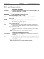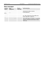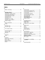
1
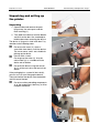
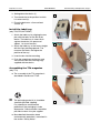
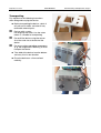
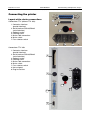
03/02 Rev. 2.14-01
USER MANUAL
TTX x50
Commissioning and Operation, Page 1
– Wildcats – S 45/65/95/105 – TDI/STDI/XXTREME
Commissioning and Operation
Unpacking and setting up the printer ..............2
Unpacking....................................................2
Install the label tray......................................3
Assembling the TT4 magazine....................3
Transporting.................................................4
Connecting the printer .....................................5
Layout of the device connections ................5
Mains cable connection...............................6
Connecting the data cable...........................7
Connecting printer options...........................8
Slide-in card modules......................................9
General information about plug-in cards .....9
Layout of the slots........................................9
Printer type and memory capacity...............9
Operating panel of the printer........................10
Layout of the operating elements ..............10
Display .......................................................10
Meanings of the buttons ............................10
Operating modes...........................................11
Off-line mode .............................................11
On-line mode .............................................11
Report status .............................................11
Basic operating procedures ..........................12
Restarting the printer .................................12
Restarting the printer (reset) .....................12
Calling up the programme version ............12
Operation in off-line mode.............................13
Off-line mode (TTX)...................................13
Off-line mode (TDI)....................................14
Operation in on-line mode.............................15
Error messages .............................................16
Index ..................................................................
17
03/02 Rev. 2.14-01
USER MANUAL
TTX x50
Commissioning and Operation, Page 2
– Wildcats – S 45/65/95/105 – TDI/STDI/XXTREME
Unpacking and setting up
the printer
Unpacking
1
1. Open the box and remove the parts
lying on top, the extra parts and the
foam covering (1).
2. Take hold of the device from the bottom
and lift it out the box. Get somebody to
hold the box when removing the device.
The device is lying on its side in the box. Pay
attention to the following notes:
3
2
Do not use the cover (2), which is
accessible from above, to lift the device.
The cover moves and is not suitable for
picking up the device.
Devices with a cutter:
Do not grasp the cutter (3). Use the
cutter motor (4) as a handle to lift the
device out of the box.
Do not lift the device using the narrow
slit (5) of the card slot at the back of the
device.
If the packaging has a material inlet slot (6),
you can use it to start lifting up the device.
Then take hold of the device from the bottom
and lift it out of the box.
Do not use other protruding components
(e. g. the magazine or label tray) to lift or
transport the device.
4
6
5
03/02 Rev. 2.14-01
USER MANUAL
TTX x50
3. Setting down the device (1).
1
4. Turn the device to the position in which
it is to be used (2).
5. Place the device on a firm and level
surface (3).
Install the label tray
(only TDI/STDI/XXTREME)
1. Attach the label tray by aligning the two
pins with the holes on the left of the
device. The label tray is almost flush
against the device (an aperture of
approx. 1 to 3 mm remains).
2
2. Attach the label tray at the correct height
with the flaps pointing upwards. T he
narrower the labels, the higher the
position of the tray.
3. Insert the bar into the mounting.
4. Push the magazine onto the two rods
and secure it with the retaining rings
supplied with the device.
Assembling the TT4 magazine
(only TT4)
The assembly of the TT4 magazine is
described in the Manual TT2/4.
Commissioning and Operation, Page 3
– Wildcats – S 45/65/95/105 – TDI/STDI/XXTREME
The packaging material (4) should be
stored for possible shipping.
Pay attention to environmental
protection if the packaging is to be
disposed of. Check whether it would be
possible to return it to your supplier.
More detailed information about
environmental protection is contained in
the section "Safety Notes".
3
4
03/02 Rev. 2.14-01
USER MANUAL
TTX x50
Transporting
Pay attention to the following instructions
when lifting and carrying the device:
Before transporting the device, switch it
off, pull out all cables and take off any
removable external parts.
Devices with a cutter:
Do not grasp the cutter. Use the cutter
motor as a handle for transporting.
Do not lift the device using the narrow
slit of the card slot at the back of the
device.
Do not use other protruding components
(e. g. the magazine or label tray) to lift or
transport the device.
Take hold of the device from the bottom
and carry it to its new location.
Place the device on a firm and level
underlay.
Commissioning and Operation, Page 4
– Wildcats – S 45/65/95/105 – TDI/STDI/XXTREME
03/02 Rev. 2.14-01
USER MANUAL
TTX x50
Commissioning and Operation, Page 5
– Wildcats – S 45/65/95/105 – TDI/STDI/XXTREME
Connecting the printer
Layout of the device connections
1
Connections TTX (without TTX 350):
1 Centronics interface
(parallel interface)
2 Serial interface RS232/RS485
(serial interface)
3 Optional socket
4 Earthing screw
5 Mains cable connection
6 Mains switch
7 Fuse selector switch
2
3
4
5
6
7
Connections TTX 350:
1 Centronics interface
(parallel interface)
2 Serial interface RS232/RS485
(serial interface)
3 Optional socket
4 Earthing screw
5 Mains cable connection
6 Mains switch
7 Fuse selector switch
8 Not assigned
9 Plug-in card slot
9
7
8
3
6
4
5
1
2
03/02 Rev. 2.14-01
USER MANUAL
TTX x50
Commissioning and Operation, Page 6
– Wildcats – S 45/65/95/105 – TDI/STDI/XXTREME
Connections TDI:
1 Centronics interface
(parallel interface)
2 Serial interface RS232/RS485
(serial interface)
3 Optional socket 1
4 Earthing screw
5 Optional socket 2
6 Type label
7 Mains cable connection
8 Mains switch
9 Voltage selector switch
3
4
5
6
7
8
9
2
1
Mains cable connection
Before connecting the device to the mains, it is necessary to check the
mains voltage setting. Dangerous contact voltage can arise if the device is
connected to the mains power supply when setting the mains voltage on
the device fuse.
Therefore, pay attention to the following:
– Never alter the voltage settings or change the fuse when the device is
connected to the mains power supply!
1. Check whether the device voltage (4)
corresponds to the local mains voltage
rating.
Normally the device is already set to the
mains voltage supply of the destination
country before it leaves the factory.
2. In order to set the mains voltage rating,
remove the insert (3), insert a suitable f use,
turn the insert and replace it.
3. Ensure that the mains switch (2) is switched
off, attach the mains cable to the connector
(1), and plug the mains plug into the main
power supply socket.
1
2
3
4
03/02 Rev. 2.14-01
USER MANUAL
TTX x50
Commissioning and Operation, Page 7
– Wildcats – S 45/65/95/105 – TDI/STDI/XXTREME
Connecting the data cable
Switch off the device before plugging in or removing the data cable, the
mains power supply connector cable or the optional connector cable!
It is only permitted to connect devices to the interfaces or the sockets which
have been tested according to IEC 950 or VDE 0805, and which comply
with these requirements in line with SELV.
Pay attention to these instructions to avoid damage to the device.
Standard
A serial interface V.24/DB25 (RS232) and parallel interface (Centronics)
are integrated as standard interfaces for connecting the printer. T he parallel
interface is the default printer setting. T he serial interface can be activated
in the parameter menu of the printer.
You can find a summary of all the parameters and settings in the chapter
"Info print-outs and parameters".
RS422
As an option, the manufacturer can replace the RS232-interface with an
RS422/RS485-interface. T he RS232-interface is then no longer available!
Information about upgrading from RS232 to RS422/RS485 can be found in
the Service chapter of the Service Manual, section "Connections and
electrics".
Only TTX 350
The serial interface of the TTX 350 can be operated either as an RS232 or
RS485 interface. T his is switched over by changing the jumper on the
mainboard.
Information about setting the jumper can be found in the Service chapter of
the Service Manual, section "Connections and electrics".
Connecting the printer to the PC:
Connect the data cable to the serial interface of the PC and – depending on
the data transmission to be used – to the serial or parallel connector
socket of the printer.
Setting the printer to serial data transmission:
1. Connect and switch on the printer:
Display OFF
2. Press FEED+CUT button:
Display INFO
3. Press CUT button repeatedly until
Display IFAC
4. Press ENTER button;
Display PORT
Continued on the next page.
03/02 Rev. 2.14-01
USER MANUAL
TTX x50
Commissioning and Operation, Page 8
– Wildcats – S 45/65/95/105 – TDI/STDI/XXTREME
5. Press ENTER button:
Display CENT
6. Press CUT button,
Display RS23
7. Press ENTER button:
Display PORT
8. Press FEED+CUT button:
Display IFAC
9. Press FEED+CUT button:
Display OFF
Connecting printer options
Optional socket
Printer options can be connected to one (TTX) or two (TDI) sockets on the
back of the device – e.g. a single-start switch or a power stacker for the
TDI.
03/02 Rev. 2.14-01
USER MANUAL
TTX x50
Commissioning and Operation, Page 9
– Wildcats – S 45/65/95/105 – TDI/STDI/XXTREME
Plug-in card modules
General information about plug-in cards
The plug-in modules are intended for the use of optional cards. PCMCIA
cards with up to 2 MB per card can be inserted. More detailed information
is contained in the card manual.
Only plug-in cards which have been approved by the manufacturer may be
used. Do not insert, remove or change a card until at least 60 seconds after
switching off the device!
Layout of the slots
Slide-in modules TTX/TDI
all
all TDI
0 Slot 0
1 Slot 1
1
0
1
0
Printer type and memory capacity
TTX 350, TTX 450, TTX 650,
TTX 950, TTX 1050
S45/65/95/105
Ocelot/Puma/Lion/Tiger/
TigerXXL
TDI/STDI/XXTREME
PCMCIA
2
2 MB
–
PCMCIA
PCMCIA
2
2
2 MB
2 MB
–
–
PCMCIA
2
2 MB
–
Refer to the card manual for more information about the card; refer to the
Easy Plug Manual for more information about programming.
03/02 Rev. 2.14-01
USER MANUAL
TTX x50
Commissioning and Operation, Page 10
– Wildcats – S 45/65/95/105 – TDI/STDI/XXTREME
Operating panel of the printer
Layout of the operating elements
Operating elements:
1 Display
1
2
4
3
2 FEED button
3 CUT button
4 ON/OFF button (=ENTER button)
Display
4-figure display
The 4-figure display shows the operating modes: parameters, values,
status and malfunctions. T he display is largely self-explanatory despite the
limited number of positions.
Meanings of the buttons
General
The small number of buttons still permit a multitude of operating functions.
The device is operated using a logical menu structure. T he buttons have
different meanings depending on the operating mode and menu item. In
addition, special functions are programmed by pressing several buttons
simultaneously.
Despite this variety, the following main f unctions can be assigned:
ON/OFF button
ONLINE/OFFLINE = on-line/off-line:
Alternates between on-line and off-line mode
ENTER button
ENTER =Enter:
Confirms values, menu items or displays
CUT button
CUT = Cut.
Also leads to deeper levels of the menu structure or selects menu items.
Values are reduced.
FEED button
FEED = material feed, in on-line-mode start after stop.
Also leads to deeper levels of the menu structure or selects menu items.
Values are increased.
FEED+CUT
FEED+CUT (pressed simultaneously) = ESC (Escape),
i.e. return to the main menu option. Also leads in off-line mode to the
parameter menu.
Other and more detailed f unction assignments can be found
– in the following sections (functions in off-line and on-line mode) and
– in the section "Info print-outs and parameters" (how to use the
parameter menu).
03/02 Rev. 2.14-01
USER MANUAL
TTX x50
Commissioning and Operation, Page 11
– Wildcats – S 45/65/95/105 – TDI/STDI/XXTREME
Operating modes
Off-line mode
Display OFF
Off-line mode is for parameter settings, status reports and printer settings.
The printer is not ready to receive data via the selected interface (off-line).
Print jobs are not carried out.
ON/OFF button
Press the ON/OFF button in order to go into on-line mode.
On-line mode
Display ON
The on-line mode is usually activated after the printer has been switched on
(adjustable). T he printer is ready for operation in the on-line mode. Data
can be received via the selected interface (on-line). Print jobs are carried
out. If Stop or Error are displayed, the printer goes automatically into offline mode.
ON/OFF button
Press the ON/OFF button in order to go into on-line mode.
Report status
Status report
A malfunction or certain conditions are signalised by the printer with a
status report. In this report status, the printer waits for the error to be
corrected and/or an acknowledgement. After acknowledgement, the printer
goes from the report status into off-line mode (depending on the error and
how the previous process has been completed).
ENTER, FEED
Acknowledge with the ENTER button and switch off the acoustical signal
with the FEED button in order to exit the report status (change to off-line).
03/02 Rev. 2.14-01
USER MANUAL
TTX x50
Commissioning and Operation, Page 12
– Wildcats – S 45/65/95/105 – TDI/STDI/XXTREME
Basic operating procedures
Restarting the printer
Connection
1. Connect the printer to the mains power supply (if not already done so) and
plug in the interface cable (if required).
Display: none
Switching on
2. Switch on the printer using the mains switch.
Display: INIT , ON (normal) or OFF (if so set)
Offline
3. If display OFF: Go to on-line mode by pressing the ON/OFF button.
Display: ON
On-line
The printer is now ready to receive data via the selected interface.
Restarting the printer (reset)
Display: Arbitrary (not off!)
Press the FEED+CUT+ON/OFF buttons (all 3 buttons simultaneously) in
Reset
order to reset the printer. T he printer is restarted (restart or also warm-up).
Display: INIT (blinking), ON
The printer can therefore be restarted without having to switch the device
off first.
During reset, all the data stored in the printer is deleted!
Calling up the programme version
Version display
Reset
The programme version (e. g. 1H34) is shown during the rest of the reset
procedure.
Press the FEED+CUT+ON/OFF buttons (all 3 buttons simultaneously) and
keep them pressed in order to see the version number! The printer is reset
and restarted.
Display: 1Hxx, INIT (blinking), ON
During reset, all the data stored in the printer is deleted!
03/02 Rev. 2.14-01
USER MANUAL
TTX x50
Commissioning and Operation, Page 13
– Wildcats – S 45/65/95/105 – TDI/STDI/XXTREME
Operation in off-line mode
Off-line mode (TTX)
Drucker
empfangsbereit
ON/OFFLINE
ENTER
ON
CUT
ON/OFFLINE
ENTER
1Hxx
ON/OFFLINE
ENTER
FEED
ONLINE
FEED
ON/OFFLINE
ENTER
OFF
CUT
FEED
CUT
FEED
<---
CUT
Vorschub
Material
Vorschub Material
langsam
Schnitt
(optional)
OFFLINE
ON/OFFLINE
ENTER
Z00030D
Reset und
Neustart
FEED
CUT
FEED
CUT
INFO
Schnitt und
Vorschub rückwärts
Previous Button
display
combinations
Display
Function/meaning
afterwards
OFF
ON/OFF
ON
On-line mode, printer is ready to receive
OFF
ON/OFF+FEED
<---
Slow material and ribbon feed
OFF
ON/OFF+CUT
OFF
FEED
FEED
Material feed
OFF
CUT
CUT
Cut
TTX 350/Ocelot: Labels between printhead and
cutter are ejected and cut.
(only if Cutter or TCS is installed and activated)
OFF
FEED+CUT
INFO
Selection parameter menu
OFF
FEED+CUT+ON/OFF INIT, OFF
Cut, then reverse feed
(doesn´t work with TTX 350/Ocelot!)
Reset by pressing the version display buttons
03/02 Rev. 2.14-01
USER MANUAL
TTX x50
Commissioning and Operation, Page 14
– Wildcats – S 45/65/95/105 – TDI/STDI/XXTREME
Off-line mode (TDI)
Drucker
empfangsbereit
ON/OFFLINE
ENTER
ON
CUT
ON/OFFLINE
ENTER
1Hxx
ON/OFFLINE
ENTER
FEED
ONLINE
FEED
ON/OFFLINE
ENTER
OFF
CUT
FEED
CUT
OFFLINE
Z00040D
Reset und
Neustart
FEED
ON/OFFLINE
ENTER
CUT
FEED
UP
FOIL
DOWN
Vorschub
Material
Magazin
nach oben
Vorschub Folie
mit ON/OFF-Taste
Magazin
nach unten
FEED
CUT
INFO
CUT
Vorschub Folie
Ende
Previous Button
display
combinations
Display
Function/meaning
afterwards
OFF
ON/OFF
ON
On-line mode, printer is ready to receive
OFF
ON/OFF+FEED
UP
Magazine pointing up, if parameter MMOD = TAG
OFF
ON/OFF+CUT
DOWN
Magazine pointing down, if parameter
MMOD = TAG
OFF
FEED
FEED
Material feed
OFF
CUT
FOIL
Slow ribbon feed when pressing ON/OFF button
OFF
FEED+CUT
INFO
Selection parameter menu
OFF
FEED+CUT+ON/OFF INIT, OFF
Reset by pressing the version display buttons
03/02 Rev. 2.14-01
USER MANUAL
TTX x50
Commissioning and Operation, Page 15
– Wildcats – S 45/65/95/105 – TDI/STDI/XXTREME
Operation in on-line mode
ON/OFFLINE
ENTER
Reset und
Neustart
FEED
CUT
ON/OFFLINE
ENTER
1Hxx
ON/OFFLINE
ENTER
OFF
FEED
CUT
ON
FEED
Aufbau
Druckbild
Druckmenge
WAIT
xxxx
CUT
HVxx
ON/OFFLINE
ENTER
Etikett fertig
drucken
Energieeinstellung
STOP
FEED
Menge bleibt
erhalten
Z00050D
ON/OFFLINE
ENTER
OFF
ON/OFFLINE
ENTER
Previous Button combination Display
Function/meaning
display
afterwards
ON
FEED+CUT
HVxx
Print head power setting: increase value with
FEED button, decrease value with CUT button
WAIT
not possible
WAIT
Creation of print image
xxxx
Display of labels to be printed, including those
being printed
xxxx
ON/OFF
STOP
The label currently being printed in printing is
completed, the display then starts to blink
STOP
xxxx
ON/OFF
OFF
Change into off-line mode (quantity remains the
same)
OFF
ON/OFF
STOP xxxx On-line mode with halted print job
STOP
xxxx
FEED
xxxx
Restart print job
03/02 Rev. 2.14-01
USER MANUAL
TTX x50
Commissioning and Operation, Page 16
– Wildcats – S 45/65/95/105 – TDI/STDI/XXTREME
Error messages
Previous Button
display
combinations
STxx
STxx
Display
afterwards
Function/meaning
ON/OFF
Status report STxx (xx = error number). Confirm
that the error has been corrected
(acknowledgement)
FEED
Switch off acoustical signal.
CUT
To exit the report status. Depending on the
error, either change into off-line mode or the
previous operation is continued
(self-acknowledging)
xxxx
Status report as a warning, self-acknowledging.
The message appears for approx. 2 seconds on
the display. T he printer then continues with its
previous job
03/02 Rev. 2.14-01
USER MANUAL
TTX x50
Commissioning and Operation, Page 17
– Wildcats – S 45/65/95/105 – TDI/STDI/XXTREME
Index
B
Buttons, meanings ......................................10
C
Centronics interface......................................5
Changing the fuse.........................................6
Check mains voltage setting.........................6
Connecting printer options............................8
Connecting the data cable............................7
Connections TDI ...........................................6
Connections TTX ..........................................5
Connections TTX 350...................................5
Connector cable, optional.............................7
Contact voltage.............................................6
D
Device connections.......................................5
Display ........................................................10
E
Earthing screw..............................................5
Error messages...........................................16
F
Fuse selector switch .....................................5
I
Install the label tray.......................................3
Interface cable ..............................................7
Interfaces ......................................................7
L
Label tray ......................................................3
LCLR .............................................................9
M
magazine.......................................................3
Mains cable connection............................5, 6
Mains switch .................................................5
Memory capacity...........................................9
MMOD ........................................................14
O
Off-line mode ..............................................11
Off-line mode, operation TDI ......................14
Off-line mode, operation TTX .....................13
On-line mode ..............................................11
On-line mode, operation.............................15
Operating elements, layout ........................10
Operating modes ........................................11
Operating panel..........................................10
Operating procedures.................................12
Optional socket.........................................5, 6
P
Packaging material.......................................3
Plug-in card...................................................9
Plug-in cards.................................................9
Programme version, display.......................12
R
Report status ..............................................11
Reset...........................................................12
Restart ........................................................12
Retaining ring................................................3
RS232-interface............................................7
S
Serial interface..............................................5
Serial interface, replacing.............................7
Setting mains voltage ...................................6
Setting serial data transmission ...................7
Setting up, printer .........................................2
Slide-in card module.....................................9
Slots, layout ..................................................9
T
TT4 magazine, assembling ..........................3
Type label .....................................................6
U
Unpacking, printer ........................................2