1
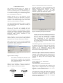
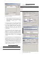
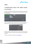
INTERFACING A PANELVIEW 660 TO A CONTROL LOGIX 5550 CONTROLLER PA Gouws, TA Harrison, PC Pelser Iscor Flat Steel Products, Vanderbijlpark Steel, Technical Training This paper describes how an Allen Bradley PanelView 600 Human Machine Interface (HMI) intended for use on the serial port of an Allen Bradley SLC processor for point to point RS-232 (DH 485) communications, can be connected point to point, to a ControlLogix 5555 controller, using the serial port on the front panel of the controller, by mapping the data tables of the SLC controller into the ControlLogix controller in order to emulate the SLC controller so that communication can be established between the HMI and the ControlLogix controller. Copyright © 2002 IFAC Keywords: PanelView, ControlLogix, Human machine interface (HMI), DH 485, MicroLogix. 1. INTRODUCTION In the technological age we find ourselves in, it is inevitable that hardware and software upgrades in the industrial control environment will always be prevalent in order to replace control equipment with new releases that have more advanced features be it hardware or software. This is also the case with the Allen Bradley 2711K6C5 PanelView human machine interface (HMI), which are designed to function with the Allen Bradley SLC controllers. With the birth of the ControlLogix controller, which replaces the SLC controller, the previous versions of the PanelView HMI, have became obsolete, not as a result of their functionality, but merely as a result of the different control structure that the ControlLogix controllers utilise. This new control structure that the ControlLogix uses is no longer compatible with the PanelView 600 HMI control structure and these two process control devices can no longer communicate with each other. All PanelView terminals have catalogue numbers. The catalogue numbers that end with a numeric five (5) have a single RS-232 communications interface. This RS-232 communications interface was intended for communication between a single 5/03, 5/04 or 5/05 SLC controller (Channel 0 port) or a MicroLogix 1000, 1200 or 1500 controller using point-to-point communications as depicted in Figure 1 and not with the newer generation ControlLogix which requires two communication interfaces in order to function. The one communications port is used to upload or download PanelView applications, which means the PanelView HMI Allen Bradley SLC Point-to-Point Connection Figure 1. HMI to SLC connection engineering of the graphics on the PanelView by means of PanelBuilder software. The other serial communication port is used for communications between the ControlLogix controller and the Panel View HMI. As the newer ControlLogix technology became available, Iscor Vanderbijlpark Steel upgraded the Allen Bradley SLC controllers to the more advanced ControlLogix controllers. The manufacturer specifications and technical plant personnel on site confirmed that the older PanelView HMI’s were no longer compatible with the new ControlLogix controllers and that all the PanelView HMI’s needed to be replaced at great cost. Additional interface units between the ControlLogix controller and the PanelView HMI where suggested in order to save on the replacement costs of replacing all PanelView HMI’s In order to reduce or eliminate this additional cost which was unplanned for, seeing as only the control systems where planned for an upgrade, an interfacing technique was researched, developed, tested and implemented to interface the PanelView HMI’s to the newly acquired ControlLogix system without any additional cost of glue logic or firmware upgrades. 2. METHODOLOGY As previously stated, the PanelView in question has only one RS232 (DH 485) interface, while the new PanelView that is designed for use with the ControlLogix controller has two communication interfaces namely: One RS232 (DH 485) communication interface used exclusively for the interfacing of the PanelView to a computer for downloading of the graphical engineering software to build the graphics on the PanelView One Allen Bradley proprietary network port used exclusively for the interfacing of the PanelView to the Control Logix controller in order to pass the variables to and from the HMI The methodology that was followed hinged around this differentiation, for if the graphical engineering software communicated from a computer to the new generation PanelView via a RS 232 communication port, then the same software could be used via the previously mentioned RS 232 port on the older generation PanelView. Once the engineering of the graphics has been done and downloaded to the new generation PanelView, the RS232 communication port essentially become obsolete as the communication between the new generation PanelView and the ControlLogix controller takes place via the proprietary network port. The older generation PanelView has only the single RS 232 communication port and all variables that where passed between the SLC controller and the old generation PanelView where passed via this interface. Logic thus dictates that if the older generation PanelView could receive the variables via the RS232 communication interface, then with additional commands, the same data should be able to be communicated via the RS232 communication port on the ControlLogix instead of the standard proprietary network port. The older generation PanelView HMI must have a dedicated point to point RS232 (DH 485) physical connection with the ControlLogix system, which requires the ControlLogix’s RS232 communication interface’s protocol to be changed to DH 485 as depicted in figure 2 and 5. This has the disadvantage that the RS 232 communication interface on the front panel of the ControlLogix controller will now be exclusively reserved for the use of the older generation PanelView. Point-to-Point Connection MCC with LCP The PanelView -indicates diagnostic and fault information of the MCC. Figure 2. Point to point serial connection However, due to the fact that the ControlLogix controller normally communicates via Ethernet, the lack of this additional communication interface has no effect on the normal operation of the ControlLogix controller. The RS 232 communication interface is normally only used when configuring the ControlLogix controller which defaults to the RS232 communication interface. Once the communication interface has been selected as Ethernet, the ControlLogix controller will not require the use of the RS232 communication interface unless communications with the Ethernet card has been lost. Simply rerouting the variables that need to be passed to the older generation PanelView via the ControlLogix controller’s RS 232 communication interface will not allow compatibility, as the older generation PanelView was designed to operate with the SLC control structure. The methodology that needed to be followed was twofold: Make use of the ControlLogix’s RS 232 communication interface to pass the HMI variables Emulate the SLC control structure within the confines of the ControlLogix controller The SLC controller can indeed communicate with the ControlLogix controller if the SLC controller’s data tables are mapped into the ControlLogix controller, the crux of the research focussed on this fact. In order for the SLC controller to communicate with the ControlLogix controller the data mapping needs to be the same. This implies that a form of emulation is taking place on the part of the ControlLogix controller. The SLC control structure can be implemented within the confines of the ControlLogix structure, the older generation PanelView which only communicates with the SLC controller would thus be able to communicate with the ControlLogix controller, as the ControlLogix controller would appear to be a SLC controller to the older generation PanelView. Figure 4. Communication interface connections 3. IMPLEMENTATION The principle described above was utilised, in layman’s terms the ControlLogix controller is ‘fooled’ into thinking that it is communicating to a SLC controller and the older generation PanelView is ‘fooled’ into thinking it is communicating with a SLC, thus emulation is achieved The same cable that is used to download the Panel Builder application into the PanelView is used to establish communications between the older generation PanelView and the ControlLogix controller as graphically depicted by Figure 4. Without affecting any of the functions of the ControlLogix controller, the data tables of the SLC controller were mapped into the ControlLogix controller so that data exchange would occur in the same way as that of the SLC controller. The older generation PanelView requires a specific one dimensional data array, formatted according to the SLC contention. This is exactly what was mapped into the ControlLogix controller thus emulating the SLC within the confines of the ControlLogix controller, allowing the transfer of parameters and data with the result being a fully functional older generation PanelView HMI directly interfaced to the ControlLogix controller. When choosing a driver from the ControlLogix software (RSLinx), for this specific older generation PanelView, the 1747-PIC driver must be selected. RSLinx may not run as a service while configuring the 1747-PIC driver. It must be selected to run as an application as depicted in figure 3. Figure 3. RSLinx settings The “Reserve COM Port for Exclusive use by this Driver” checkbox must be enabled. This ensures that RSLinx works properly if it is running as a service. RSLinx can be forced to start as a service by selecting: Start > Programs > Rockwell Software > RSLinx > RSLinx Launch Control Panel. DTE (PC) DCE (PanelView) 1 5 9 6 Required Pins Figure 5. DH 485 system protocol selection In order for the older generation PanelView to communicate with the ControlLogix controller and vice versa, the ControlLogix’s controller system protocol must be changed to DH485. This configuration of the ControlLogix controller is illustrated in figure 5. The power to the controller must be recycled in order for the settings to take effect. The addressing principle of data inside the SLC must be understood in order to emulate the SLC structure within the ControlLogix controller, similarly the structure of the ControlLogix must be fully understood in order to implement the mapping of the SLC into the ControlLogix controller. When 16 bit data in the SLC controller is required by the ControlLogix controller and the data in the SLC controller is for example stored in registers N7:0 to N7:4, the data can be mapped into the ControlLogix controller by making use of the RsLogix 5000 software . From the menu bar: LOGIC>MAP PLC/SLC MESSAGES. FILE NUMBER=7. TAG NAME=SLC_DATA (See Figure 6) Files N7:0 to N7:4 inside the SLC controller’s N7 register must be mapped inside the ControlLogix controller in a one dimensional integer array with a length of 5 as shown in table 1 and 2. 1 5 9 6 Required Pins 2 (TXD) 2 (TXD) 3 (RXD) 3 (RXD) 5 (SG) 5 (SG) If the function of timers and counters are required, the values of these elements must be manipulated within the ControlLogix controller in order to fit inside 16 bit registers, which must then be mapped into the SLC data structure. Table 2. ControlLogix mapping Tag name: SLC_DATA CLX Address SLC_DATA (0) SLC_DATA (1) SLC_DATA (2) SLC_DATA (3) SLC_DATA (4) 16 Bit Data 0 1 0 1 0 1 0 1 0 1 0 1 0 1 0 1 1 0 1 0 1 0 1 0 1 0 1 0 1 0 1 0 1 0 1 0 1 0 1 0 1 0 1 0 1 0 1 0 1 0 1 0 1 0 1 0 1 0 1 0 1 0 1 0 0 1 0 1 0 1 0 1 0 1 0 1 0 1 0 1 Figure 6. SLC mapping The ControlLogix timers and counters can’t be directly mapped to the SLC controller as the SLC controller uses a 48-bit architecture and the ControlLogix controller uses a 96-bit architecture. The mapping inside the older generation PanelView is exactly the same as for a SLC controller. If the tag inside the older generation PanelView requests access to data originating from Integer Files N7:0 to N7:4 in the ControlLogix controller, N7 should be available and mapped as SLC data inside the ControlLogix to a one dimensional integer array with a length of five. The SLC structure allows for valid file numbers ranging from 0 to 999. Only one data file may be mapped to a unique tag. The older generation PanelView will communicate with this data structure within the ControlLogix controller via the RS 232 communication interface of the ControlLogix controller, which is set up to use the DH485 protocol. If a message operates on a file number that has no mapping associated with it, the message will fail. Bit addressing within the structure is not possible, this means mapping a specific element number or bit is an illegal operation and will not execute with the result that no communication will take place, only a file number may be used in the transmission of variables between the older generation PanelView and the ControlLogix controller. Table 1. SLC controller mapping SLC Address N7:0 N7:1 N7:2 N7:3 N7:4 16 Bit Data 0 1 1 1 0 1 0 0 0 1 0 1 1 1 0 1 0 0 0 1 0 1 1 1 0 1 0 0 0 1 0 1 1 1 0 1 0 0 0 1 0 1 1 1 0 1 0 0 0 1 0 1 1 1 0 1 0 0 0 1 0 1 1 1 0 1 0 0 0 1 0 1 1 1 0 1 0 0 0 1 Figure 7. PanelView set-up The tag mapped to a SLC file, must be a controller scoped tag. As many tags as required may be mapped using this structure. the back plane and configured via the programming terminal. The older generation PanelView reconnected and all communications will be restored. Figure 7 depicts the initial set up of the older generation PanelView. The specific series and catalogue number should be selected from the list provided. REFERENCES The node address of the SLC processor starts at 1, and the node type selected is SLC 5/05. The PanelView node address will be 2. 4. CONCLUSION This paper shows that it is possible to fully utilise the older generation PanelView HMI and interface it with the newer generation ControlLogix controller without adding any additional interfaces, by emulating the SLC controller structure by mapping the SLC data tables within the confines of the ControlLogix controller in the form of a one dimensional array and by doing so, the older PanelView HMI’s operate with full functionality. There are only two drawbacks to the implementation of this methodology as described in this paper. The first is the internal manipulation of data that will be required to performed within the ControlLogix controller when a timer or counter’s data needs to be transferred between the two devices. This is a result of the different architectures that are implemented in the older generation PanelView (48 bits) as opposed to the ControlLogix (96 bits) Once this conversion is done, the two systems will operate transparently. The second drawback is that if the Ethernet card is damaged or becomes non functional, all the communications between the various ControlLogix control systems and the programming terminal will cease. In order to gain access from the programming terminal, the following action needs to be implemented. The ControlLogix processor can be removed and placed in another functional back plane. Communications with the processor will be established via the Ethernet card in the new back plane. The primary communication of the processor must be reset to RS232 (DH485). The processor must be returned to the original back plane. The older generation PanelView’s communication cable must be removed and replaced with the serial cable of the programming terminal. Communication will now be established with the processor and a new Ethernet card can be placed into PanelView operator terminal user manual (Publication 2771-6.1)