1
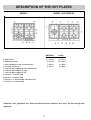
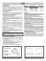
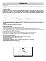
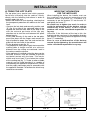
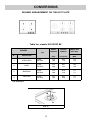
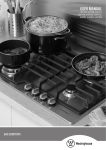
INSTRUCTIONS AND ADVICE FOR THE
USE, INSTALLATION AND MAINTENANCE
OF MIXED AND GAS FUELLED
BUILT-IN HOT PLATES
Dear Customer,
Thank you for having purchased one of our products.
We are certain that this new, modern, functional and practical appliance, built with the very highest
quality materials, will meet your requirements in the best possible way. This appliance is easy to use. It
is, however, important to thoroughly read the instructions in this handbook in order to obtain the best
results.
The manufacturer shall not be held responsible for any damages to persons or property caused by
incorrect installation or use of the appliance.
MODELS: HIG 95223 SX - SAP CODE: 8946233200
The Manufacturer shall not be held responsible for any inaccuracies in this handbook due to printing or
transcription errors; the designs in the figures are purely indicative. The Manufacturer also reserves the right to
make any modifications to the products as may be considered necessary or useful, also in the interests of the
user, without jeopardizing the main functional and safety features of the products themselves.
COD. 04037HI - 23.02.2012
DESCRIPTION OF THE HOT PLATES
MODEL:
MODEL: HIG 95223 SX
NATURAL
1 Wok burner
2 Rapid gas burner
3 Semi rapid gas burner (front and rear)
4 Auxiliary gas burner
5 Cast iron pan support for ultra rapid burner
6 Cast iron pan support 2F right
7 Cast iron pan support 2F left
8 Burner n° 1 control knob
9 Burner n° 2 control knob
10 Burner n° 3 control knob (front and rear)
11 Burner n° 4 control knob
13.5 MJ/h
12.0 MJ/h
7.1 MJ/h
4.1 MJ/h
U-LPG
11.4 MJ/h
10.4 MJ/h
6.3 MJ/h
3.6 MJ/h
Attention: this appliance has been manufactured for domestic use only. Do not modify this
appliance.
2
USE
1) BURNERS
Burners
A diagram is screen-printed above each knob on the
front panel. This diagram indicates to which burner
the knob in question corresponds. After having
opened the gas mains or gas bottle tap, light the
burners as described below:
- manual ignition
Push and turn the knob corresponding to the
required burner in an anticlockwise direction until it
reaches the full on position (large flame fig. 1), then
place a lighted match near the burner.
- Automatic electrical ignition
Push and turn the knob corresponding to the
required burner in an anticlockwise direction until it
reaches the full on position (large flame fig. 1), then
depress the knob.
- Lighting burners equipped with flame failure
device
The knobs of burners equipped with flame failure
device must be turned in an anticlockwise direction
until they reach the full on position (large flame
fig. 1) and come to a stop. Now depress the knob in
question and repeat the previously indicated
operations.
Keep the knob depressed for about 10 seconds
once the burner has ignited.
Note: you are advised not to try and light a
burner if the flame divider (Burner Cap) is not
correctly placed.
Ultra rapid
Rapid
Semirapid
Auxiliary
Power ratings
NATURAL U-LPG
13.5 MJ/h 11.4 MJ/h
12.0 MJ/h 10.4 MJ/h
7.1 MJ/h 6.3 MJ/h
4.1 MJ/h 3.6 MJ/h
Pan Ø in cm
22 ÷ 24
20 ÷ 22
16 ÷ 18
10 ÷ 14
WARNINGS:
- burners with flame failure device may only be
ignited when the relative knob has been set to
the Full on position (large flame fig. 1).
- Matches can be used to ignite the burners in a
blackout situation.
- Never leave the appliance unattended when the
burners are being used. Make sure there are no
children in the near vicinity. Particularly make
sure that the pan handles are correctly
positioned and keep a check on foods requiring
oil and grease to cook since these products can
easily catch fire.
- Never use aerosols in the vicinity of this appliance
while it is in operation.
- If the built-in hot plate has a lid, any spilt food
should be immediately removed from this
before it is opened. If the appliance has a glass
lid, this could shatter when the hot plate
becomes hot. Always switch off all the burners
before closing the lid.
- Do not store or use flammable liquids or items
in the vicinity of the hotplate.
- For UNIVERSAL LP GAS appliances - where this
appliance is installed in marine craft or in
caravans, it shall not be used as a space heater.
In the event of the Burner flames being accidentally
extinguished, turn off the burner control and do not
attempt to re-ignite the burner for a least 1 minute.
HOW TO USE THE BURNERS
Bear in mind the following indications in order to
achieve maximum efficiency with the least possible
gas consumption:
- use adequate pans for each burner (consult the
following table and fig. 2).
- When the pan comes to the boil, set the knob to the
reduced rate position (small flame fig. 1).
- Always place a lid on the pans.
- Use only pan with a flat bottom and in thick metal.
FIG. 1
FIG. 2
3
USE
Notes:
use of a gas cooking appliance produces heat and moisture in the room in which it is installed. The
room must therefore be well ventilated by keeping the natural air vents clear (fig. 3) and by activating
the mechanical aeration device (suction hood or electric fan fig. 4 and fig. 5).
Intensive and lengthy use of the appliance may require additional ventilation. This can be achieved by
opening a window or by increasing the power of the mechanical exhausting system if installed.
Abnormal Operation:
any of the following are considered to be abnormal operation and may require servicing:
- yellow tipping of the hob burner flame.
- Sooting up of cooking utensils.
- Burners not igniting properly.
- Burners failing to remain alight.
- Burners extinguished by cupboard doors.
- Gas valves which are difficult to turn.
(*) Air inlet - minimum section 100 cm2
FIG. 3
FIG. 4
4
FIG. 5
CLEANING
IMPORTANT:
always disconnect the appliance from the gas and electricity mains before carrying out any cleaning
operation.
2) HOT PLATE
Periodically wash the hot plate, the enamelled steel pan support, the enamelled burner caps “C” and the
burner heads “T” (see fig. 6) with lukewarm soapy water. Following this, all parts should be thoroughly rinsed
and dried. Never wash them while they are still warm and never use abrasive powders. Do not allow vinegar,
coffee, milk, salted water, lemon or tomato juice from remaining in contact with the enamelled surfaces for long
periods of time.
WARNINGS:
comply with the following instructions, before remounting the parts:
- check that burner head slots “T” (fig. 6) have not become clogged by foreign bodies.
- Check that enamelled burner cap “C” (fig. 6) have correctly positioned on the burner head. It must be
steady.
- The exact position of the pan support is established by the rounded corners, which should be set
towards the side edge of the hot plate.
- Do not force the taps if they are difficult to open or close. Contact the technical assistance service for
repairs.
- Don’t use steam jets for cleaning the cooktop.
CARE & MAINTENANCE
To optimise the appearance and up keep of stainless steel:
1) ALWAYS keep stainless steel out of contact from acid/acid based solvent (liquid or vapour form).
2) After installation, wipe clean all stainless steel products with a soft damp cloth to remove any traces of dirt
(e.g. cement dust) or condensation marks.
In the event where persistent marks appear:
immediately clean affected areas with stainless steel cleaner, using a clean damp soft cloth.
Ensure surface is rinsed and thoroughly clean of all marks and stainless steel cleaner.
PREVENTATIVE MAINTENANCE
This cooktop should not require ongoing maintenance provided you ensure:
- all spillages are cleaned up as soon as they occur.
- Burners are kept clean.
- Burner ports are free of debris, food or anything else that may cause an obstruction.
- Electrode and thermocouples are kept clean.
- Burners are re-assembled correctly.
- Do not get water in the area where the injectors are located.
FIG. 6
5
INSTALLATION
TECHNICAL INFORMATION FOR
INSTALLATION PERSONNEL
3) INSTALLING THE HOT PLATE
Check that the appliance is in a good condition after
having removed the outer packaging and internal
wrappings from around the various loose parts. In
case of doubt, do not use the appliance and contact
qualified personnel.
Never leave the packaging materials
(cardboard, bags, polystyrene foam, nails, etc.)
within children’s reach since they could become
potential sources of danger.
The measurements of the opening made in the top
of the modular cabinet and into which the hot plate
will be installed are indicated in fig. 7.
Always comply with the measurements given for the
hole into wich the appliance will be recessed (see
fig. 7 and 8).
The appliance belongs to class 3 and is
therefore subject to all the provisions
established by the provisions governing such
appliances.
This appliance shall be installed only by
authorised persons and in accordance with the
manufacturer's installation instructions, local
gas fitting regulations, municipal building
codes, electrical wiring regulations, AS 5601/AG
601 - Gas Installations and any other statutory
regulations.
The wall and bench surfaces must be capable of
sustaining temperatures of 75 degrees Celsius.
All laminates, fixing adhesive and surfacing
materials should be certified suitable for this
temperature.
Any adjoining wall surface situated within 200mm
from the edge of any hob burner must be a suitable
non-combustible material for a height of 150mm for
the entire length of the hob. Any combustible
construction above the hotplate must be at least
650mm above the top of the burner and no
construction shall be within 450mm above the top
of the burner. A minimum depth of 70mm from the
top of the worktop surface must be provided for the
appliance.
COMPLY WITH THE DIMENSIONS
Overall Dimensions 4F: 580 x 500 mm
Overall Dimensions 5F: 680 x 500 mm
4F (580)
5F (860)
A
553
833
B
473
475
FIG. 7
C
63.5
62.5
D
E
63.5 100 min.
62.5 73.5 min.
FIG. 8
6
4) FIXING THE HOT PLATE
INSTALLATION
IMPORTANT INFORMATION
FOR THE INSTALLER
The hot plate has a special seal which prevents
liquid from infiltrating into the cabinet. Strictly
comply with the following instructions in order to
correctly apply this seal:
- detach the seals from their backing, checking that
the transparent protection still adheres to the seal
itself.
- Overturn the hot plate and correctly position seal
“E” (fig. 9) on top of the upturned edge of the
hotplate flat with the outer side of the strip in line
with the external perimeter of the top, pay
attention not to sink the seal between the space
bottom/top rim.
- Evenly and securely fix the seal to the hot plate,
press into place with the fingers and remove the
strip of protective paper from the seal and set the
plate into the hole made in the cabinet.
- Fix the brackets as per fig. 10.
- The prospective walls (left or right) that exceed the
working table in height must be at a minimum
distance from the cutting as mentioned both in
the columns and the scheme.
- If the appliance is installed so that the base can be
touched, a barrier must be installed to prevent
accidental contact with the base. This barrier
shield must be at least 70 mm below the surface
of the working top (fig. 7). Timber or other suitable
material may be used provided it is capable of
withstanding the appliance temperatures. Ensure
that the supply connection point is accessible with
the appliance installed. To facilitate the shield may
need to be removable.
FIG. 9
When installing the device, the installer must use
the supplied fixing brackets according to the
scheme shown in picture 10. Therefore it is
necessary to put the bracket "S" into the slot "H"
and tighten the screw "F".
Be careful not to tighten too much, in order to
avoid the deformation of the bottom and the
malfunction of the device. In this case the
producer will not be considered responsible in
any way.
Viceversa, if the thickness of the top is thin, the
brackets can be used even in the opposite direction
(see picture 10/A), being careful to tighten the fixing
screw "F" moderately.
Even in case of deformation of the bottom
caused by the tightening, the manufacturer will
not be considered responsible in any way.
FIG. 10
7
FIG. 10/A
5) GAS CONNECTION
INSTALLATION
Natural Gas
Natural Gas installations require the connection of a
gas regulator at the appliance. This regulator is
supplied with the appliance on purchase.
Assemble the regulator (noting the gas flow
direction) and transition pieces (supplied with the
appliance), in accordance with figure 11.
The transition piece on the supply side of the
regulator must be provided by the installer.
Liquified Petroleum Gas
In a Universal LP Gas installation the gas regulation
is made at the gas cylinder and regulation at the
appliance is not required. To connect supply to the
appliance use transition pieces as shown in
figure 12. These pieces are supplied with the
appliance on purchase.
The gas connection is located in the rear and on the
underside of the appliance 118 mm (for 60 cm),
165 mm (for 70 cm), 255 mm (for 90 cm) from the
right hand side.
There are two ways to carry out the connection to the
main gas line:
A. The hotplate can be connected with rigid pipe as
specified in AS5601 table 3.1.
B. The hotplate can be connected with a Flexible
Hose,which complies with AS/ANZ 1869 (AGA
Approved), 10mm ID, class B or D, no more than
1.2m long and in accordance with AS5601.
Ensure that the Hose does not contact the hot
surfaces of the hotplate, oven, dishwasher or other
appliance that may be installed underneath or next to
the hotplate. The Hose should not be subjected to
abrasion, kinking or permanent deformation and
should be able to be inspected along its entire length.
Unions compatible with the hose fittings must be
used and connections tested for gas leaks.
Ensure the supply connection point is accessible with
the appliance installed.
Warning: ensure that the hose assembly is restrained
from accidental contact with the flue or flue outlet of
an underbench oven.
WARNING:
THE BURNER FLAME MUST BE ADJUSTED BY
THE INSTALLER.
FAULTY INSTALLATION WILL NOT BE
COVERED UNDER WARRANTY.
THE APPLIANCE IS FACTORY SET FOR NATURAL
GAS. THE TEST POINT PRESSURE SHOULD BE
ADJUSTED TO 1.00kPa WITH THE WOK BURNER
OPERATING AT MAXIMUM.
FIG. 11
FIG. 12
8
INSTALLATION
6) ELECTRICAL CONNECTION
THE APPLIANCE MUST BE EARTHED
Ensure that this power point is properly earthed.
Look at the connection wiring diagrams
(fig. 13 and 13/A).
Warning: in order to avoid any hazard, any
electrical work performed on this equipment or
its associated wiring, should only be done by
persons authorised by the supplier or similarly
qualified persons.
The socket outlet for this hotplate shall be
installed near the hotplate and shall be easily
accessible.
The appliance is supplied with a 1800 mm long
flexible supply lead.
The point of attachment for this lead is located at the
rear and on the underside of the appliance
380 mm from the right hand side.
The voltage and power consumption are detailed on
the underside of the appliance. Ensure that the
appliance is correctly rated to the supply.
Connect appliance by way of a switched power point.
FIG. 13
FIG. 13/A
9
ADJUSTMENTS
7) TAPS
Always disconnect the appliance from the
electricity main before making any adjustments.
All seals must be replaced by the technician at
the end of any adjustments or regulations.
Our burners do not require primary air
adjustment.
a) Data Label
The Data Label is located on the underside of the
hotplate. A duplicate Data Label is supplied to adhere
in an accessible area next to the hotplate. This
hotplate is suitable for Natural Gas and Universal LP
Gas; ensure that the available gas supply matches
the Data Label.
b) Before Leaving
Check that there are no gas leaks, but do not use a
naked flame to detect gas leaks. Ignite all burners to
ensure correct operation of gas valves, burners,
ignition and if fitted, flame failure valves. Turn gas
taps to low flame position and observe stability of the
flame. When satisfied with the hotplate, please
instruct the user on the correct method of operation.
In case the appliance fails to operate correctly after
all checks have been carried out, refer to the
authorised service provider in your area.
Our taps are suitable for all the gas, they are male
conical type at one way.
“Reduced rate” adjustment
- Switch on the burner and turn the relative knob to
the “Reduced rate” position (small flame fig. 1).
- Remove knob “M” (fig. 14) of the tap, which is simply
pressed on to its rod.
- Insert a small screwdriver “D” into hole “C” (fig. 14)
and turn the throttle screw to the right or left until the
burner flame has been adequately regulated to the
“Reduced rate” position.
Check that the flame does not go out when the knob
is sharply switched from the “Full on” to the “Reduced
rate” position.
It is understood that only burners operating with
Natural gas should be subjected to the above
mentioned adjustments. The screw must be fully
locked when the burners operate with Propane
Gas.
FIG. 14
10
CONVERSIONS
8)UNIVERSAL LP GAS TO NATURAL
GAS CONVERSION PROCEDURE
5. Remove the Universal LP Gas test point inlet
fitting from the appliance.
6. Fit the Natural Gas Regulator supplied in the
conversion kit.
7. Connect the gas supply to the Regulator.
8. Check for gas leaks. Do not use a naked flame
to check for gas leaks.
9. Adjust the gas pressure to 1.00 kPa.
10. Remove the control knob, with a thin shaft blade
screwdriver down the centre of each gas valve
shaft, screw the by-pass injector anti-clockwise.
Test the appliance on both high and low flame for
each burner. If the burner fails to remain alight or
the flame is not stable on the simmer setting, adjust
the by-pass screw, until flame is stable.
11. If not already removed, remove the “Only for
use with Universal LP Gas” label adhered to the
bottom panel near the gas connection.
12. Fit the new data label included in the gas
conversion kit.
Appliance models: Gas stainless steel hotplate
models:
HIG 95223 SX
5 Burners
1. Remove each burner cap and burner skirt.
2. Remove the Universal LP Gas main injector with
a 7 mm/VF tube spanner and replace with the
appropriate size Natural Gas main injector for each
burner. The following injector sizes are required for
Natural Gas:
Burner
Main injector
Wok
Rapid
Semi Rapid
*Auxiliary
1.70 mm
1.55 mm
1.20 mm
0.90 mm
3. Shut off gas supply to the appliance.
4. Disconnect gas inlet pipe from the Universal LP
Gas test point inlet fitting.
*For 4 Burners
11
CONVERSIONS
9) NATURAL GAS TO UNIVERSAL LP
GAS CONVERSION PROCEDURE
5. Disconnect gas inlet pipe from the Natural Gas
Regulator.
6. Remove the Natural Gas Regulator from the
appliance.
7. Fit the Universal LP Gas test point inlet fitting
supplied in the conversion kit.
8. Connect the gas supply to the inlet fitting.
9. Check for gas leaks. Do not use a naked flame
to check for gas leaks.
10. Adjust the gas pressure to 2.75 kPa.
11. Test the appliance on both high and low flame
for each burner and check the gas pressure. If the
burner fails to remain alight or the flame is not
stable on the simmer setting, adjust the by-pass
screw until flame is stable.
12. If not already removed, remove the “Only for
use with Natural Gas” label adhered to the bottom
panel near the gas connection.
13. Fit the new data label included in the gas
conversion kit.
Appliance models: Gas stainless steel hotplate
models:
HIG 95223 SX
5 Burners
1. Remove each burner cap and burner skirt.
2. Remove the Natural Gas main injector with a
7 mm/VF tube spanner and replace with the
appropriate size Universal LP Gas main injector for
each burner. The following injector sizes are
required for Universal LP Gas:
Burner
Main injector
Wok
Rapid
Semi Rapid
*Auxiliary
0.94 mm
0.91 mm
0.70 mm
0.53 mm
3. Remove the control knob, with a thin shaft blade
screwdriver down the centre of each gas valve
shaft, screw the by-pass injector fully clockwise.
4. Shut off gas supply to the appliance.
*For 4 Burners
12
CONVERSIONS
BURNER ARRANGEMENT ON THE HOT PLATE
Table for: models HIG 95223 SX
BURNERS
GAS
NORMAL
PRESSURE
INJECTOR
DIAMETER
NOMINAL HEAT
INPUT (MJ/h)
(kPa)
(1/100 mm)
MAX.
N°
DESCRIPTION
1
ULTRA RAPID
U-LPG
NATURAL
2.75
1.00
0.94
1.70
11.4
13.5
2
RAPID
U-LPG
NATURAL
2.75
1.00
0.91
1.55
10.4
12.0
3
SEMIRAPID
U-LPG
NATURAL
2.75
1.00
0.70
1.20
6.3
7.1
4
*AUXILIARY
U-LPG
NATURAL
2.75
1.00
0.53
0.90
3.6
4.1
*For 4 Burners
FIG. 15
13
SERVICING
WARNING:
servicing should be carried out only by
authorised personnel.
Greasing the taps (see fig. 20 - 21)
If a tap becomes stiff to operate, it must be
immediately greased in compliance with the
following instructions:
- remove the tap.
- Clean the cone and its housing using a cloth
soaked in solvent.
- Lightly spread the cone with the relative grease.
- Fit the cone back in place, operate it several times
and then remove it again. Eliminate any excess
grease and check that the gas ducts have not
become clogged.
- Fit all parts back in place, complying with the
demounting order in reverse.
- Check the tightness by using soapy water. The use
of the flame is prohibited.
10) COMPONENTS REPLACEMENT
NOTE:
BEFORE ANY MAINTENANCE REQUIRING
REPLACEMENT OF A COMPONENT IS
UNDERTAKEN
ENSURE
THAT
THE
ELECTRICAL LEAD HAS BEEN ISOLATED AND
REMOVED FROM THE POWER POINT.
To replace the components fit inside the hob is
necessary to take off the pan supports and the
burners from the upper part of the working table,
then unscrew the burner fixing screws “V” (fig. 16)
and the control knobs, fixed by a simple pressure, in
order to take off the working table.
After having carried out the above listed operations,
the burners (fig. 17), taps (fig. 18) and electrical
components can all be replaced (fig. 19).
It is advisable to change seal “D” each time a tap is
changed in order to ensure a perfect tightness.
To facilitate the servicing technician’s task, here is a
chart with the types and sections of the powering
cables and the ratings of the electrical components.
FIG. 16
FIG. 17
FIG. 18
FIG. 19
FIG. 20
FIG. 21
14
SERVICING
CABLE TYPES AND SECTIONS
TYPE OF
HOT PLATE
Gas hot plate
TYPE OF
CABLE
SINGLE - PHASE
POWER SUPPLY
H05 RR - F
Section 3 x 0.75 mm
2
ATTENTION!!!
If the power supply cable is replaced, the installer should leave the ground wire longer than the phase
conductors (fig. 22) and comply with the recommendations given in paragraph 6.
FIG. 22
15
TECHNICAL ASSISTANCE AND SPARE PARTS
Before leaving the factory, this appliance will have been tested and regulated by expert and specialized
personnel in order to guarantee the best performances.
Any repairs or adjustments which may be subsequently required may only be carried out by qualified
personnel with the utmost care and attention.
For this reason, always contact your Dealer or our nearest After Sales Service Center whenever repairs or
adjustments are required, specifying the type of fault and the model of the appliance in your possession.
Please also note that genuine spare parts are only available from our After Sales Service Centers and
authorized retail outlets.
The above data are printed on the data label put on the inferior part of the appliance and on the packing label.
The above informations give to the technical assistant the possibility to get fit spare parts and a heaven-sent
intervention. We suggest to fill the table below.
MARK: ........................................................
MODEL: .....................................................
SERIES: .....................................................
16