1
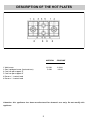
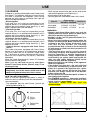
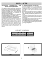
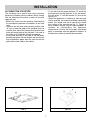
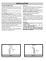
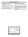
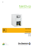
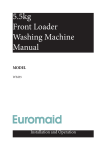
USE, INSTALLATION AND MAINTENANCE
INSTRUCTIONS FOR BUILT-IN HOT PLATES
Dear Customer
Thank you for purchasing a Blanco Cooktop.
Before we continue telling you about this cooktop, we cordially invite you to become part of the Blanco family by
subscribing to ongoing information and invitations. Please visit our website where you can subscribe and request
such things as invitations to future cooking classes and gourmet recipes. Go to www.meaappliances.com.au and
fill in the subscription details.
You will find that the clean lines and modern look of your Blanco Cooktop blends perfectly with your kitchen décor.
It is easy to use and performs to a high standard.
Blanco also makes a range of products that will enhance your kitchen such as ovens, rangehoods, dishwashers,
microwaves, sinks and taps.
There are models to complement your new Blanco Cooktop.
Of course we make every effort to ensure that our products meet all your requirements, and our Customer
Relations department is at your disposal, to answer your questions and to listen to all your suggestions (see back
cover of manual).
Please complete the warranty section of this manual and keep your receipt as proof of purchase. Retain all
documents relating to the purchase of this products.
Blanco is committed to providing increasingly efficient products that are easy to use, respect the environment and
are attractive and reliable.
BLANCO
MODELS: CG904WWXC - CG904WWXFFC
We ask that you carefully read the instructions within this booklet to enable you to abtain quality results from the outset.
The appliance must be installed only by an authorised person in compliance with the instructions provided. The manufacturer
declines all responsability for improper installation which may harm persons and animals and damage property.
The appliance must be used for the purpose for which it was expressly designed. Any other use (eg heating rooms) is considered to
be improper and consequently dangerous. The manufacturer declines all responsability for damage resulting from improper and
irresponsible use.
The manufacturer shall not be held responsible for any inaccuracies in this handbook due to printing or transcription errors. The
designs in the figures are purely indicative.
The manufacturer also reserves the right to make any modifications to the products as may be considered necessary, useful or in the
interests of the user, without jeopardizing the main functional and safety features on the products themselves.
If your cooktop requires service, please contact your local customer service centre or your nearest Blanco agent listed at the back of
this booklet.
COD. 04031GGZB - 13.05.2010
DESCRIPTION OF THE HOT PLATES
1 Wok burner
3 Semi rapid gas burner (front and rear)
4 Cast iron pan support 1F
5 Cast iron pan support 2F
6 Burner n° 1 control knob
8 Burner n° 3 control knob
NATURAL
PROPANE
13.0 MJ
5.4 MJ
11.0 MJ
6.0 MJ
Attention: this appliance has been manufactured for domestic use only. Do not modify this
appliance.
2
USE
1) BURNERS
- When the pan comes to the boil, set the knob to the
reduced rate position (small flame fig. 1).
- Always place a lid on the pans.
- Use only pan with a flat bottom and in thick metal.
A diagram is screen-printed above each knob on the
front panel. This diagram indicates to which burner
the knob in question corresponds. After having
opened the gas mains or gas bottle tap, light the
burners as described below:
- Manual ignition
Push and turn the knob corresponding to the
required burner in an anticlockwise direction until it
reaches the full on position (large flame fig. 1), then
place a lighted match near the burner.
- Electrical ignition
Push and turn the knob corresponding to the
required burner in an anticlockwise direction until it
reaches the full on position (large flame fig. 1), then
depress and release the ignition button.
- Automatic electrical ignition
Push and turn the knob corresponding to the
required burner in an anticlockwise direction until it
reaches the full on position (large flame fig. 1), then
depress the knob.
- Lighting burners equipped with flame failure
device
The knobs of burners equipped with flame failure
device must be turned in an anticlockwise direction
until they reach the full on position (large flame
fig. 1) and come to a stop. Now depress the knob in
question and repeat the previously indicated
operations.
Keep the knob depressed for about 10 seconds
once the burner has ignited.
Note: you are advised not to try and light a
burner if the flame divider (Burner Cap) is not
correctly placed.
In the event of the Burner flames being accidentally
extinguished, turn off the burner control and do not
attempt to re-ignite the burner for a least 1 minute.
Burners
Ultra rapid
Semirapid
Power ratings
Pan Ø in cm
NATURAL PROPANE
13.0 MJ/h 11.0 MJ/h 22 ÷ 24
16 ÷ 18
5.4 MJ/h 6.0 MJ/h
WARNINGS:
- Burners with flame failure device may only be
ignited when the relative knob has been set to
the Full on position (large flame fig. 1).
- Matches can be used to ignite the burners in a
blackout situation.
- Never leave the appliance unattended when the
burners are being used. Make sure there are no
children in the near vicinity. Particularly make
sure that the pan handles are correctly
positioned and keep a check on foods requiring
oil and grease to cook since these products can
easily catch fire.
- The machine must not be used by people
(including children) with impaired mental or
physical capacities, or without experience of
using electrical devices, unless supervised or
instructed by an expert adult responsible for
their care and safety. Children should not be
allowed to play with the equipment.
- Never use aerosols in the vicinity of this appliance
while it is in operation.
- If the built-in hot plate has a lid, any spilt food
should be immediately removed from this
before it is opened. If the appliance has a glass
lid, this could shatter when the hot plate
becomes hot. Always switch off all the burners
before closing the lid.
- Do not store or use flammable liquids or items in
the vicinity of the hotplate.
- For PROPANE appliances - where this appliance
is installed in marine craft or in caravans, it shall
not be used as a space heater.
- Containers wider than the unit are
recommended.
HOW TO USE THE BURNERS
Bear in mind the following indications in order to
achieve maximum efficiency with the least possible
gas consumption:
- Use adequate pans for each burner (consult the
following table and fig. 2).
FIG. 1
FIG. 2
3
USE
Notes:
Use of a gas cooking appliance produces heat and moisture in the room in which it is installed. The
room must therefore be well ventilated by keeping the natural air vents clear (fig. 3) and by activating
the mechanical aeration device (suction hood or electric fan fig. 4 and fig. 5).
Intensive and lengthy use of the appliance may require additional ventilation. This can be achieved by
opening a window or by increasing the power of the mechanical exhausting system if installed.
Abnormal Operation:
Any of the following are considered to be abnormal operation and may require servicing:
- Yellow tipping of the hob burner flame.
- Sooting up of cooking utensils.
- Burners not igniting properly.
- Burners failing to remain alight.
- Burners extinguished by cupboard doors.
- Gas valves which are difficult to turn.
(*) Air inlet - minimum section 100 cm2
FIG. 3
FIG. 4
4
FIG. 5
CLEANING
IMPORTANT:
Always disconnect the appliance from the gas and electricity mains before carrying out any cleaning
operation.
2) HOT PLATE
Periodically wash the hot plate, the enamelled steel pan support, the enamelled burner caps “C” and the
burner heads “T” (see fig. 6) with lukewarm soapy water. Following this, all parts should be thoroughly rinsed
and dried. Never wash them while they are still warm and never use abrasive powders. Do not allow vinegar,
coffee, milk, salted water, lemon or tomato juice from remaining in contact with the enamelled surfaces for long
periods of time.
WARNINGS:
Comply with the following instructions, before remounting the parts:
- Check that burner head slots “T” (fig. 6) have not become clogged by foreign bodies.
- Check that enamelled burner cap “C” (fig. 6) have correctly positioned on the burner head. It must be
steady.
- The exact position of the pan support is established by the rounded corners, which should be set
towards the side edge of the hot plate.
- Do not force the taps if they are difficult to open or close. Contact the technical assistance service for
repairs.
- Don’t use steam jets for cleaning the cooktop.
CARE & MAINTENANCE
To optimise the appearance and up keep of stainless steel:
1) ALWAYS keep stainless steel out of contact from acid/acid based solvent (liquid or vapour form).
2) After installation, wipe clean all stainless steel products with a soft damp cloth to remove any traces of dirt
(e.g. cement dust) or condensation marks.
In the event where persistent marks appear:
Immediately clean affected areas with stainless steel cleaner, using a clean damp soft cloth.
Ensure surface is rinsed and thoroughly clean of all marks and stainless steel cleaner.
PREVENTATIVE MAINTENANCE
This cooktop should not require ongoing maintenance provided you ensure:
- All spillages are cleaned up as soon as they occur.
- Burners are kept clean.
- Burner ports are free of debris, food or anything else that may cause an obstruction.
- Electrode and thermocouples are kept clean.
- Burners are re-assembled correctly.
- Do not get water in the area where the injectors are located.
FIG. 6
5
INSTALLATION
TECHNICAL INFORMATION FOR
INSTALLATION PERSONNEL
3) INSTALLING THE HOT PLATE
Check that the appliance is in a good condition after
having removed the outer packaging and internal
wrappings from around the various loose parts. In case of
doubt, do not use the appliance and contact qualified
personnel.
Never leave the packaging materials (cardboard,
bags, polystyrene foam, nails, etc.) within children’s
reach since they could become potential sources of
danger.
The measurements of the opening made in the top of the
modular cabinet and into which the hot plate will be installed are
indicated in fig. 7.
Always comply with the measurements given for the hole into
wich the appliance will be recessed (see fig. 7 and 8).
The appliance belongs to class 3 and is therefore subject
to all the provisions established by the provisions
governing such appliances.
This appliance shall be installed only by authorised
persons and in accordance with the manufacturer's
installation instructions, local gas fitting regulations,
municipal building codes, electrical wiring
regulations, AS 5601/AG 601 - Gas Installations and
any other statutory regulations.
The wall and bench surfaces must be capable of
sustaining temperatures of 75 degrees Celsius.
All laminates, fixing adhesive and surfacing materials
should be certified suitable for this temperature.
Any adjoining wall surface situated within 200mm from the
edge of any hob burner must be a suitable noncombustible material for a height of 150mm for the entire
length of the hob. Any combustible construction above the
hotplate must be at least 650mm above the top of the
burner and no construction shall be within 450mm above
the top of the burner. A minimum depth of 60mm from the
top of the worktop surface must be provided for the
appliance.
COMPLY WITH THE DIMENSIONS
4F (860)
A
B
C
D
E
833
475
62.5
62.5
73.5 min.
FIG. 7
FIG. 8
6
4) FIXING THE COOKTOP
INSTALLATION
- Fix the hob with the proper brackets “S” and fit the
prominent part into the porthole “H” on the bottom;
turn the screw “F” until the bracket “S” stick on the
top (fig. 10).
- When the appliance is installed so that the base
can be touched, we recommend fitting a protecting
shield. This shield must be at least 60 mm below
the surface of the working top (fig. 7). Timber or
other suitable material may be used provided it is
capable of withstanding the appliance
temperatures. Ensure that the supply connection
point is accessible with the appliance installed. To
facilitate the shield may need to be removable.
The hot plate has a special seal which prevents
liquid from infiltrating into the cabinet. Strictly comply
with the following instructions in order to correctly
apply this seal:
- detach the seals from their backing, checking that
the transparent protection still adheres to the seal
itself.
- Overturn the hot plate and correctly position seal
“E” (fig. 9) under the edge of the hot plate itself, so
that the outer side of the seal perfectly matches the
outer perimetral edge of the hot plate. The ends of
the strips must fit together without overlapping.
- Evenly and securely fix the seal to the hot plate,
pressing into place with the fingers and remove the
strip of protective paper from the seal and set the
plate into the hole made in the cabinet.
FIG. 9
FIG. 10
7
5) GAS CONNECTION
INSTALLATION
Natural Gas
Natural Gas installations require the connection of a
gas regulator at the appliance. This regulator is
supplied with the appliance on purchase.
Assemble the regulator (noting the gas flow
direction) and transition pieces (supplied with the
appliance), in accordance with figure 11.
The transition piece on the supply side of the
regulator must be provided by the installer.
Liquified Petroleum Gas
In a PROPANE installation the gas regulation is
made at the gas cylinder and regulation at the
appliance is not required. To connect supply to the
appliance use transition pieces as shown in figure
12. These pieces are supplied with the appliance on
purchase.
The gas connection is located in the rear and on the
underside of the appliance 118 mm (for 60 cm),
165 mm (for 70 cm), 255 mm (for 90 cm) from the
right hand side.
There are two ways to carry out the connection to the
main gas line:
A. The hotplate can be connected with rigid pipe as
specified in AS5601 table 3.1.
B. The hotplate can be connected with a Flexible
Hose,which complies with AS/ANZ 1869 (AGA
Approved), 10mm ID, class B or D, no more than
1.2m long and in accordance with AS5601.
Ensure that the Hose does not contact the hot
surfaces of the hotplate, oven, dishwasher or other
appliance that may be installed underneath or next to
the hotplate. The Hose should not be subjected to
abrasion, kinking or permanent deformation and
should be able to be inspected along its entire length.
Unions compatible with the hose fittings must be
used and connections tested for gas leaks.
Ensure the supply connection point is accessible with
the appliance installed.
Warning: Ensure that the hose assembly is
restrained from accidental contact with the flue or
flue outlet of an underbench oven.
WARNING:
THE BURNER FLAME MUST BE ADJUSTED BY
THE INSTALLER.
FAULTY INSTALLATION WILL NOT BE
COVERED UNDER WARRANTY.
THE APPLIANCE IS FACTORY SET FOR NATURAL
GAS. THE TEST POINT PRESSURE SHOULD BE
ADJUSTED TO 1.00kPa WITH THE WOK BURNER
OPERATING AT MAXIMUM.
FIG. 11
FIG. 12
8
INSTALLATION
6) ELECTRICAL CONNECTION
THE APPLIANCE MUST BE EARTHED
Ensure that this power point is properly earthed.
Look at the connection wiring diagrams
(fig. 13).
Warning: In order to avoid any hazard, any
electrical work performed on this equipment or
its associated wiring, should only be done by
persons authorised by the supplier or similarly
qualified persons.
The socket outlet for this hotplate shall be
installed near the hotplate and shall be easily
accessible.
The appliance is supplied with a 1800 mm long
flexible supply lead.
The point of attachment for this lead is located at the
rear and on the underside of the appliance
380 mm from the right hand side.
The voltage and power consumption are detailed on
the underside of the appliance. Ensure that the
appliance is correctly rated to the supply.
Connect appliance by way of a switched power point.
FIG. 13
9
ADJUSTMENTS
7) TAPS
Always disconnect the appliance from the
electricity main before making any adjustments.
All seals must be replaced by the technician at
the end of any adjustments or regulations.
Our burners do not require primary air
adjustment.
a) Data Label
The Data Label is located on the underside of the
hotplate. A duplicate Data Label is supplied to adhere
in an accessible area next to the hotplate. This
hotplate is suitable for Natural Gas and Propane Gas;
ensure that the available gas supply matches the
Data Label.
b) Before Leaving
Check that there are no gas leaks, but do not use a
naked flame to detect gas leaks. Ignite all burners to
ensure correct operation of gas valves, burners,
ignition and if fitted, flame failure valves. Turn gas
taps to low flame position and observe stability of the
flame. When satisfied with the hotplate, please
instruct the user on the correct method of operation.
In case the appliance fails to operate correctly after
all checks have been carried out, refer to the
authorised service provider in your area.
Our taps are suitable for all the gas, they are male
conical type at one way.
“Reduced rate” adjustment
- Switch on the burner and turn the relative knob to
the “Reduced rate” position (small flame fig. 1).
- Remove knob “M” (fig. 14) of the tap, which is simply
pressed on to its rod.
- Insert a small screwdriver “D” into hole “C” (fig. 14)
and turn the throttle screw to the right or left until the
burner flame has been adequately regulated to the
“Reduced rate” position.
Check that the flame does not go out when the knob
is sharply switched from the “Full on” to the “Reduced
rate” position.
It is understood that only burners operating with
Natural gas should be subjected to the above
mentioned adjustments. The screw must be fully
locked when the burners operate with PROPANE
gas.
FIG. 14
10
CONVERSIONS
8) PROPANE GAS TO NATURAL GAS
CONVERSION PROCEDURE
6. Fit the Natural Gas Regulator supplied in the
conversion kit.
7. Connect the gas supply to the Regulator.
8. Check for gas leaks. Do not use a naked flame
to check for gas leaks.
9. Adjust the gas pressure to 1.00 kPa.
10. Remove the control knob, with a thin shaft blade
screwdriver down the centre of each gas valve
shaft, screw the by-pass injector anti-clockwise.
Test the appliance on both high and low flame for
each burner. If the burner fails to remain alight or
the flame is not stable on the simmer setting, adjust
the by-pass screw, until flame is stable.
11. If not already removed, remove the “Only for
use with Propane Gas” label adhered to the bottom
panel near the gas connection.
12. Fit the new data label included in the gas
conversion kit.
Appliance models: Gas stainless steel hotplate
models:
CG904WWXC
4 Burners
CG904WWXFFC 4 Burners
1. Remove each burner cap and burner skirt.
2. Remove the Propane Gas main injector with a
7 mm/VF tube spanner and replace with the
appropriate size Natural Gas main injector for each
burner. The following injector sizes are required for
Natural Gas:
Burner
Main injector
Wok
Semi Rapid
1.60 zE mm
1.05 zA mm
3. Shut off gas supply to the appliance.
4. Disconnect gas inlet pipe from the Propane Gas
test point inlet fitting.
5. Remove the Propane Gas test point inlet fitting
from the appliance.
11
CONVERSIONS
9) NATURAL GAS TO PROPANE GAS
CONVERSION PROCEDURE
5. Disconnect gas inlet pipe from the Natural Gas
Regulator.
6. Remove the Natural Gas Regulator from the
appliance.
7. Fit the Propane Gas test point inlet fitting
supplied in the conversion kit.
8. Connect the gas supply to the inlet fitting.
9. Check for gas leaks. Do not use a naked flame
to check for gas leaks.
10. Adjust the gas pressure to 2.75 kPa.
11. Test the appliance on both high and low flame
for each burner and check the gas pressure. If the
burner fails to remain alight or the flame is not
stable on the simmer setting, adjust the by-pass
screw until flame is stable.
12. If not already removed, remove the “Only for
use with Natural Gas” label adhered to the bottom
panel near the gas connection.
13. Fit the new data label included in the gas
conversion kit.
Appliance models: Gas stainless steel hotplate
models:
CG904WWXC
4 Burners
CG904WWXFFC 4 Burners
1. Remove each burner cap and burner skirt.
2. Remove the Natural Gas main injector with a
7 mm/VF tube spanner and replace with the
appropriate size Propane Gas main injector for
each burner. The following injector sizes are
required for Propane Gas:
Burner
Main injector
Wok
Semi Rapid
0.91 zE mm
0.68 zE mm
3. Remove the control knob, with a thin shaft blade
screwdriver down the centre of each gas valve
shaft, screw the by-pass injector fully clockwise.
4. Shut off gas supply to the appliance.
12
CONVERSIONS
BURNER ARRANGEMENT ON THE HOT PLATE
TABLE
BURNERS
GAS
NORMAL
PRESSURE
(kPa)
INJECTOR
DIAMETER
(1/100 mm)
NOMINAL
HEAT
INPUT (MJ/h)
MAX.
N°
DESCRIPTION
1
ULTRA RAPID
PROPANE
NATURAL
2.75
1.00
91 zE
160 zE
11.0
13.0
3
SEMIRAPID
PROPANE
NATURAL
2.75
1.00
68 zE
105 zA
6.0
5.4
FIG. 15
13
BY PASS
1/100 mm
68
68
35
35
SERVICING
WARNING:
Servicing should be carried out only by
authorised personnel.
Greasing the taps (see fig. 20 - 21)
If a tap becomes stiff to operate, it must be
immediately greased in compliance with the
following instructions:
- Remove the tap.
- Clean the cone and its housing using a cloth
soaked in solvent.
- Lightly spread the cone with the relative grease.
- Fit the cone back in place, operate it several times
and then remove it again. Eliminate any excess
grease and check that the gas ducts have not
become clogged.
- Fit all parts back in place, complying with the
demounting order in reverse.
- Ceck the tightness by using soapy water. The use
of the flame is prohibited.
10) COMPONENTS REPLACEMENT
NOTE:
BEFORE ANY MAINTENANCE REQUIRING
REPLACEMENT OF A COMPONENT IS
UNDERTAKEN
ENSURE
THAT
THE
ELECTRICAL LEAD HAS BEEN ISOLATED AND
REMOVED FROM THE POWER POINT.
To replace the components fit inside the hob is
necessary to take off the pan supports and the
burners from the upper part of the working table, then
unscrew the burner fixing screws “V” (fig. 16) and the
control knobs, fixed by a simple pressure, in order to
take off the working table.
After having carried out the above listed operations,
the burners (fig. 17), taps (fig. 18) and electrical
components can all be replaced (fig. 19).
It is advisable to change seal “D” each time a tap is
changed in order to ensure a perfect tightness.
To facilitate the servicing technician’s task, here is a
chart with the types and sections of the powering
cables and the ratings of the electrical components.
FIG. 16
FIG. 17
FIG. 18
FIG. 19
FIG. 20
FIG. 21
14
SERVICING
CABLE TYPES AND SECTIONS
TYPE OF
HOT PLATE
Gas hot plate
TYPE OF
CABLE
H05 RR - F
SINGLE - PHASE
POWER SUPPLY
Section 3 X 0.75 mm2
ATTENTION!!!
If the power supply cable is replaced, the installer should leave the ground wire longer than the phase
conductors (fig. 22) and comply with the recommendations given in paragraph 6.
FIG. 22
15
TECHNICAL ASSISTANCE AND SPARE PARTS
MEA Contact Information.
NEW SOUTH WALES
SOUTH AUSTRALIA & NORTHERN TERRITORY
Head Office, Sales & Marketing Office
104 Vanessa Street
Kingsgrove NSW 2208
Telephone:
02 9503 2888
Facsimile:
02 9503 2810
Agent and Sales Office
S C Lighting & Electrical Supplies
47 North Terrace
Hackney SA 5069
Telephone:
08 8362 4599
Facsimile:
08 8362 4591
NSW Showroom*
40 Ebley Street
Bondi Junction NSW 2022
Telephone:
02 9386 1190
Facsimile:
02 9386 1671
Service and Spare Parts Metro
Prestige Appliance Repair Centre
Telephone:
08 8352 2022
Facsimile:
08 8352 3044
Service and Spare Parts Metro
All General Whitegoods Service
Telephone:
02 8788 8666
Facsimile:
02 9756 1091
WESTERN AUSTRALIA
State Office
4/8 Ellen Stirling Boulevard.
Innaloo
WA 6018
Telephone:
1300739033
AUSTRALIAN CAPITAL TERRITORY
Service and Spare Parts Metro
Detlevs Appliance & Electrical Care
1/88 Sheppard Street
Hume
ACT 2905
Telephone:
02 6260 1033
Facsimile:
02 6260 1035
Service and Spare Parts Metro
Metropolitan Appliance Repairs
Telephone:
08 9330 1724
Facsimile:
08 9317 1296
TASMANIA
VICTORIA
Agent and Sales Office
35 Centre Road
Scoresby VIC 3179
Telephone:
Facsimile:
State Office and Showroom*
35 Centre Road
Scoresby VIC 3179
Telephone:
03 8756 7888
Facsimile:
03 8756 7907
Service and Spare Parts Metro
Advantage Appliances
Telephone:
03 9874 4222
Facsimile:
03 9874 6917
Service and Spare Parts
Electrical Equipment Service (Launceston)
Telephone:
03 6339 3873
Facsimile:
03 6339 4588
Baldocks Appliance Service (Hobart)
Telephone:
03 6234 5995
Facsimile:
03 6234 8134
QUEENSLAND
State Office and Showroom*
148 Robinson Road - East
Geebung
QLD 4034
Telephone:
07 3259 2555
Facsimile:
07 3265 6933
MEA CUSTOMER SERVICE
Service and Spare Parts Metro
Endeavour Appliances
Telephone:
07 3137 3633
Facsimile:
07 3137 3663
1300 739 033
Website:
www.meaappliances.com.au
www.blanco-australia.com.au
www.dedietrich.com.au
Platinum Appliance Service
Telephone:
07 3862 1154
Facsimile:
07 3862 1114
Roshad (Gold Coast)
Telephone
Facsimile
03 8756 7888
03 8756 7907
* Contact Showrooms to confirm hours of business.
07 5535 7044
07 5535 7407
16
WARRANTY SECTION
BLANCO COOKING PRODUCT WARRANTY
1.Subject to the “Statement of Standard Warranty
Conditions” this product is covered by the following
Warranty.
TWO (2) YEARS WARRANTY from date of purchase,
covering all parts and labour.
2. The appliance is warranted under normal single family
domestic installation and use, as set out in the instruction
manual, against manufacturing defects for the Warranty
periods shown above.
3. Should service be required under this Warranty, the
purchaser should contact an approved BLANCO Service
Provider during their normal business hours.
4. At no time does BLANCO/MEA have liability for any
freight or transportation costs or for any damage during
transit or for any consequence of failure of this appliance
outside of the normal service area, unless such limitation
of liability is prohibited by statute.
5. This Warranty excludes replacement of parts required
due to normal wear and tear including light globes.
6. This Warranty only applies, provided the appliance has
been used in accordance with the manufacturer’s
instructions and provided an accident, misuse, neglect or
abuse has not damaged the appliance.
STATEMENT OF STANDARD
WARRANTY CONDITIONS
1. The Warranty only applies provided that the appliance
has been used in accordance with the manufacturer’s
instructions and provided that the appliance has not been
damaged by an accident, misuse, neglect or abuse of
any person other than the manufacturer or
BLANCO/Major Electrical Appliances (“MEA”) or from
faulty installation, mis-adjustment or tampering by
unauthorised persons.
2. When a service inspection reveals the alleged fault or
faults are caused by incorrect operation, contrary to the
instruction manual, and otherwise the appliance is in
good order and working condition, the purchaser shall be
liable for a service fee charged by BLANCO/MEA or one
of its’ Service Providers.
3. If the appliance is used in Commercial Applications or for
Rental purposes, a separate warranty of Twelve (12)
months covering all parts with Three (3) months on the
labour will apply.
4. Subject to the provisions of any applicable statute this
Warranty applies to the original retail purchaser only and
is not transferable.
5. Subject to the provisions of any applicable statute, at no
time does BLANCO/MEA have liability for freight,
transport or travel costs outside normal service areas.
7. None of the above Warranties purport to exclude, restrict
or modify either the application or the exercise of a right
conferred by any applicable Statute.
6. None of the above Warranties purport to exclude, restrict
or modify either the application or the exercise of a right
conferred by any applicable statute.
8. Please complete the details below, which should be
retained for future reference along with your proof of
purchase:
7. Subject to any Warranties implied by statute, at no time
will BLANCO/MEA or its’ Service Providers be liable for
any economic loss consequent upon the failure of the
appliance.
Date of Purchase: …………………………….......................
Model No: ………………………………………......................
Serial No: ………………………………………......................
Notice to Victorian Customers from the Victorian Plumbing Industry
8. This Warranty is only valid for major appliances imported
and distributed by BLANCO/MEA, purchased and used in
Australia.
Commission.
This product must be installed by a licenced person as required by the
Victorian Building Act 1993.
Only a licenced person will give you a Compliance Certificate, showing that the
work complies with all the relevant standards. Only a licenced person will have
insurance protecting their workmanship for 6 years. Make sure you use a
licenced person to install this product and ask for your Compliance Certificate.
17
MEA0304
18
19
20