Transcript
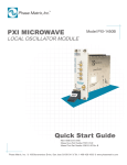
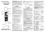
INSTRUCTION MANUAL
1. Safety Warnings
DANGER
●Make sure to set the function selector switch to the appropriate position
This instrument has been designed and tested according to IEC Publication 61010:
before making measurement. Use extreme caution not to avoid applying
Safety Requirements for Electronic Measuring Apparatus. This instruction manual
voltage to the instrument with the range selector switch set to a current or
contains warnings and safety rules which must be observed by the user to ensure
safe operation of the instrument and retain it in safe condition. Therefore, read
through these operating instructions before using the instrument.
resistance range.
●Do not attempt to make measurement in the presence of flammable gasses,
fumes, vapor or dust. Otherwise, the use of the instrument may cause
sparking, which can lead to an explosion.
● Never attempt to use the instrument if its surface or your hand is wet.
●Do not exceed the maximum allowable input of the selected measuring
WARNING
●Read through and understand instructions contained in this manual before
range.
● Never open the instrument when making measurement.
starting using the instrument.
●Save and keep the manual handy to enable quick reference whenever
necessary.
WARNING
●Be sure to use the instrument only in its intended applications and to follow
measurement procedures described in the manual.
●Be sure to understand and follow all safety instructions contained in the
manual.
●Never attempt to make any measurement if any abnormal conditions are
noted, such as broken case, cracked test leads and exposed metal parts.
●Do not turn the function selector switch with test leads connected to the
instrument.
Failure to follow the above instructions may cause injury, instrument damage
and/or damage to equipment under test.
●Do not install substitute parts or make any modification to the instrument.
●Do not try to replace the batteries or fuse if the surface of the instrument is
wet.
indicated on the instrument means that the user must refer to related
parts in the manual for safe operation of the instrument. Be sure to carefully read
the instructions following each
serious or fatal injury.
WARNING is reserved for conditions and actions that can cause serious or
fatal injury.
CAUTION is reserved for conditions and actions that can cause injury or
instrument damage.
B
When the meter pointer does not deflect, replace the fuse with the spare fuse,
which is supplied with the instrument. If there is still no deflection, the test leads
may have an open. Replace the test leads.
● Adjusting Meter Pointer Zero
Turn the zero adjust screw to set the meter pointer to the "0" mark on the
extreme left of the scale for accurate measurement.
D
E
Range
DC.V
AC.V
DC.A
Ω
Scale Used
0.3V
B
30
× 0.01
3V
B
30
× 0.1
LED
● Checking Function Selector Switch Setting
Make sure to set the function selector switch to the appropriate position.
Otherwise, intended measurement cannot be made, or injury or instrument
damage may result.
When the order of voltage or current under test is unknown, first make
measurement on the highest range, and then select the appropriate range.
6. How to Make Measurements
12V
C
12
×1
30V
B
30
×1
120V
C
12
× 10
300V
B
30
× 10
600V
C
6
× 100
12V
C
12
×1
30V
B
30
×1
120V
C
12
× 10
300V
B
30
× 10
600V
C
6
× 100
60μA
C
6
× 10
30mA
B
30
×1
300mA
B
30
× 10
(1)Plug the red test lead into the + terminal and the black test lead into the - terminal.
(2)Set the function selector switch to the appropriate DCV or ACV position.
(3)Connect the test leads to the circuit under test so the instrument is in parallel
with the circuit. In DCV measurement, the meter pointer deflects to the right
(normal direction) when the red test lead is connected to the positive side of the
circuit under test and the black test lead to the negative side of the circuit.
Connecting the test leads the other way will reverse the pointer deflection.
(4)Take reading on the appropriate scale.
×1
A
Ω
×1
Current Measurements (DCA)
× 10
A
Ω
× 10
× 100
A
Ω
× 100
BATT.TEST 1.5V※1 E
TEMP.
How to Read Scale
D
2.0
×1
-20 ∼ 150 × 1
Regardless of indicated value
※ 1 :The thick portion of the scale indicates the allowable range of
voltage of a battery. (The lower limit of voltage for a 1.5V dry
battery specified by IEC 60086 is 0.9V.) Note that satisfactory
indication on the meter may not mean the battery has enough
power for high load (high current consumption) application.
When the instrument will not be in use for a long period of time, place it in
storage after removing the batteries.
●Do not expose the instrument to the direct sun, extreme temperatures or
abrasives or solvents.
● Checking Test Leads and Fuse
Plug the red test lead into the + terminal and the black test lead into the - terminal,
and set the function selector switch to a position in the Ω area. Then, short the test
lead tips. When the meter pointer deflects to the right, proceed to measurement.
C
appropriate terminal on the instrument.
●Be sure to set the function selector switch to the OFF position after use.
●Use a damp cloth and detergent for cleaning the instrument. Do not use
5. Preparation
A
●Always make sure to insert each plug of the test leads fully into the
dewfall.
KYORITSU ELECTRICAL INSTRUMENTS
WORKS,LTD.
4. How to Read Scales
the instrument for battery replacement.
CAUTION
DANGER is reserved for conditions and actions that are likely to cause
MODEL 1110
●Always set the function selector switch to the OFF position before opening
symbol in this manual.
KYORITSU MULTIMETER
Voltage Measurements (ACV, DCV)
DANGER
● Do not make measurement on a circuit above 600V AC or DC.
● Do not apply voltage that exceeds the rated voltage of the selected range.
● Do not turn the function selector switch during measurement.
● Do not touch the metal parts of the test leads during measurement.
●When the order of the voltage under test is unknown, make measurement
on the highest range.
DANGER
● Exercise caution not to apply voltage to the instrument set to a current range.
● Do not turn the function selector switch knob during measurement.
●Make sure to firmly connect the test leads to the circuit under test so that the
connections will not become loose. The test leads must be connected to or
removed from the circuit under test with the circuit powered off.
●When the order of the current under test is unknown, make measurement on
the highest range.
(1)Plug the red test lead into the + terminal and the black test lead into the - terminal.
(2)Set the function selector switch to the appropriate DCA position.
(3)Power off the circuit under test.
(4)Connect the test leads to the circuit under test so the instrument is in series with
the circuit. In DCA measurement, the meter pointer deflects to the right (normal
Ranges
DC.V 0.3V
3V
12V
30V
120V
300V
600V
12V
AC.V
30V
120V
300V
600V
DC.A 60μA
30mA
300mA
Ω
×1
× 10
× 100
BATT.TEST 1.5V
TEMP.※ 2
LED
Return the instrument to Kyoritsu or your distributor for repair or recalibration.
The symbol
2. Specifications
direction) when the red test lead is connected to the positive side of the circuit
under test and the black test lead to the negative side of the circuit. Connecting
the test leads the other way will reverse the pointer deflection.
(5)Power on the circuit under test.
(6)Take reading on the appropriate scale.
3. Instrument Layout
● Measuring ranges and accuracy (23 ± 5:, 75%RH or less)
Measuring Range
0 ∼ 0.3V
(16.7kΩ/V)
0 ∼ 3V
0 ∼ 12V
0 ∼ 30V
(20kΩ/V)
0 ∼ 120V
0 ∼ 300V
0 ∼ 600V
0 ∼ 12V
(9kΩ/V)
0 ∼ 30V
0 ∼ 120V
(9kΩ/V)
0 ∼ 300V
0 ∼ 600V
0 ∼ 60μA (Terminal voltage:0.3V approx.)
0 ∼ 30mA(Terminal voltage:0.4V approx.)
0∼300mA (Terminal voltage:1V approx.)※1
0 ∼ 3kΩ (30Ω at mid-scale)
0 ∼ 30kΩ (300Ω at mid-scale)
0 ∼ 300kΩ(3kΩ at mid-scale)
0.7∼2.0V(Load resistance:10Ω approx.)
Accuracy
± 3% of full scale value
± 4% of full scale value
± 3% of full scale value
±3% of full scale value
Meter Cover
Test Lead Tips
±3% of full scale length
± 3% of scale length
Pointer
±3% of scale length
0 ∼ 100:
Ranges other than the above(-20∼150:) ±4% of scale length
Scale Plate
10mA approx. at 0Ω(at 3V of battery voltage)
Buzzer beeps below about 100Ω
Meter Zero
Adjust Screw
Ohm Zero
Adjust Knob
※ 1 : Small differences may result depending on the resistance of the fuse.
※ 2 : With optional temperature probe MODEL 7060.
● Standards:
:IEC 61010-1
Over-voltage category CAT.e 300V, pollution degree 2
Over-voltage category CAT.w 600V, pollution degree 2
IEC 61010-2-031
IEC 61326 (EMC)
● Meter Movement:
Self-shielding core magnet, taut-band type
● Fuse:
Fast acting type(F500mA/600V),φ 6.3x32mm
● Overload Protection:
AC/DC600V: fused (Current/Resistance/0.3V/BATT. TEST
1.5V ranges)
AC/DC720V: 10 seconds (600/300/120V ranges)
AC/DC120V: 10 seconds (30/12V ranges)
AC/DC30V:10 seconds(3V range)
● Withstand Voltage:
AC3700V for one minute between internal circuit and
housing case
● Drop Protection:
From a height of 1m onto concrete floor
● Operating Temperature
0-40:, relative humidity up to 85% without condensation
& Humidity:
● Storage Temperature
-10-50:, relative humidity up to 85% without condensation
& Humidity:
● Dimensions:
94(L)× 140(W)× 39(D)mm
● Weight:
Approx. 280g(including batteries)
● Power Source:
Two R6P(1.5V) or equivalent batteries
● Accessories:
Test leads MODEL 7066 ………………… 1
R6P battery………………………………… 2
Fuse (F500mA/600V) …………………… 2
Carrying case ……………………………… 1
Instruction manual ………………………… 1
● Optional Accessories: Temperature probe MODEL 7060
(2)Set the function selector switch to the 'BATT. TEST 1.5V' position.
(3)Connect the red test leads to the positive side of the battery and the black test
lead to the negative side of the battery.
(4)Take reading on the BATT TEST scale.
Note: The less power a battery has, the lower the reading on this range becomes
compared to the reading on the 3V DC range.
Test Leads
+Terminal
−Terminal
Front Panel
Carrying Case
Function Selector Switch
DISTRIBUTOR
Resistance/Continuity Check
DANGER
● Exercise caution not to apply voltage to the instrument set to a resistance range.
● Make sure to power off the circuit under test.
― Resistance Measurement ―
(1)Plug the red test lead into the + terminal and the black test lead into the - terminal.
(2)Set the function selector switch to the appropriate resistance position.
(3)Short the test lead tips. Turn the Ohm Zero Adjust Knob to set the meter
pointer to the "0" mark on the extreme right of the scale for accurate
measurement. Make this adjustment whenever the function selector switch is
turned to a different resistance position. When the zero adjustment cannot be
made, replace the batteries.
(4)Connect the test leads to the circuit under test.
(5)Take reading using the appropriate multiplying factor.
Note: Note that keeping the test lead tips shorted will exhaust the internal batteries.
― Continuity Check ―
(1)Plug the red test lead into the + terminal and the black test lead into the - terminal.
(2)Set the function selector switch to the ' ' position.
(3)Connect the test leads to the circuit under test.
(4)Check if there is a sound of the buzzer. The buzzer beeps below about 100Ω.
Note: The meter does not read on this range.
― LED Check ―
(1)Plug the red test lead into the + terminal and the black test lead into the - terminal.
(2)Set the function selector switch to the x10 position.
(3)Connect the test leads to the LED under the light-up test.
(4)When the LED does not light up, connect the test leads the other way.
Note: Connect the red test lead to the anode of the LED and the black test lead
to the cathode. The meter deflection has no meaning on this range.
― Temperature (TEMP.) Measurements ―
(1)Plug the red test lead into the + terminal and the black test lead into the - terminal.
(2)Set the function selector switch to the x10 position.
(3)Short the test lead tips. Turn the Ohm Zero Adjust Knob to set the meter pointer
to the "0" mark on the extreme right of the scale for accurate measurement.
(4)Remove both red and black test reads from the instrument.
(5)Plug the red lead of temperature probe Model 7060 to the + terminal and the
black lead to the - terminal.
(6)Touch the object under test with the tip of the temperature probe and take
reading on the TEMP scale.
7. Battery & Battery Replacement
WARNING
●To avoid electric shock hazard, be sure to set the function selector switch to
the OFF position and remove the test leads from the instrument.
● Replacement fuse must have the following rating.
Fast acting type, F500mA/600V,φ 6.3 × 32mm
CAUTION
● Do not mix new and old batteries.
● Install the batteries observing correct polarity shown inside the instrument.
(1)Remove the test leads from the terminals on the instrument and set the function
selector switch to the OFF position.
(2)Loosen the screw on the bottom of the instrument and remove the bottom case
from the instrument.
(3)Replace the batteries or fuse with new one(s). Use;
Two R6P dry batteries
A fast acting type fuse: F500mA/600V,φ 6.3 × 32mm
(4)Mount the bottom case and tighten the screw.
Note: Use the spare fuse stored inside the instrument. After using the spare fuse,
store a new one as a new spare.
Kyoritsu reserves the rights to change specifications
or designs described in this manual without notice
and without obligations.
Bottom Case
−
Fuse
+
+
−
Battery Test (BATT. TEST 1.5V)
This range measures the voltage of a battery, applying a load similar to that used
in common applications (load resistance: 10Ω).
DANGER
● Do not apply voltage above the rated voltage for the battery test.
● Do not turn the function selector switch during a test.
(1)Plug the red test lead into the + terminal and the black test lead into the - terminal.
Spare Fuse
10 ―07
92 ― 1430B