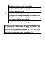
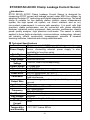
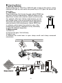
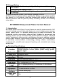
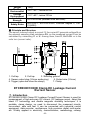
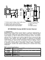
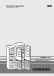
1
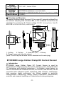
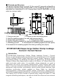
Warning
Thanks for your purchase of Leakage Current Sensor/Current Sensor
of our company. For better use of the product, please make sure:
---to read this user manual in details.
---to abide by the safety regulations and precautions strictly.
uUnder any circumstance, it shall pay special attention on safety in use of
this sensor.
uPay attention to words and symbols stick on the panel.
uKeep the pliers clean, maintenance regularly.
uStop using the sensor when there is a rupture or break.
uFor high voltage sensors, if the voltage of tested circuitry has exceeded
600V, it must be used by connecting with an insulation rod.
uThe operator must get strict training and the relevant certification.
uPlease don’t keep or store the sensor in the spot with high-temperature
and moisture, or condensation, and under direct daylight radiation for a
long time.
uFor the sensors that need battery power supply, please remove the
battery if you expect not to use the sensor for a long time, and take note of
the polarity when replace the battery.
uReplace battery in time when the battery voltage is low.
uIn case of explosion, please don’t remove or replace the battery in
dangerous places.
uFor the sensors that need external power supply, please first confirm the
polarity of power supply.
uThis sensor is only to be used, disassembled, and repaired by qualified
personnel with authorization.
uWhen it may cause hazard by continuous use for the reason of the sensor
itself, it shall immediately stop using it and deposit it at once, leaving it for
disposal by authorized agency.
u “
” in the manual is the safety warning sign, the contents of this
manual must be followed for safe operation.
u “
” and other safety signs, the contents of this manual must be
followed for safe operation.
-1-
Clamp positive line and negative line together to measure
leakage current of this DC line. (Note: 2 wires)
Clamp positive line or negative line separately to measure the
DC current of this line. (Note: single wire)
Clamp live wire or null line separately to measure the current
of this line. (Note: single wire)
Clamp live wire and null line together to measure leakage
current of single phase. (Note: 2 wires)
Clamp earth wire to measure grounding line leakage current
of electrical equipment. (Note: single wire)
Clamp three wires together to measure the leakage current of
three phase three wires.(Note: 3 wires)
Clamp four wires together to measure the leakage current of
three phase four wires.(Note: 4 wires)
The sensors output a current signal, and the secondary current can
be transferred to voltage output by parallel connecting a load
resistance RL. For example, coils turn 1000:1, when input 1000A
current signal, the secondary current will be 1A, if RL is 1Ω, it will get
1V voltage output. That means, output voltage is in proportion to the
input as 1mV/A. Please refer manual for the value of RL.
-2-
CONTENT
ETCR007AD………………………………………………………………………4
ETCR008………………………………………………………………………… 7
ETCR030………………………………………………………………………… 9
ETCR030D………………………………………………………………………10
ETCR030D1…………………………………………………………………… 10
ETCR035AD…………………………………………………………………… 12
ETCR040…………………………………………………………………………14
ETC033H…………………………………………………………………………16
ETCR048H……………………………………………………………………… 18
ETCR080…………………………………………………………………………20
ETCR080A ………………………………………………………………………20
ETCR080D ………………………………………………………………………22
ETCR085K ………………………………………………………………………24
ETCR148…………………………………………………………………………26
ETCR148A ………………………………………………………………………26
-3-
ETCR007AD AC/DC Clamp Leakage Current Sensor
ⅠIntroduction
ETCR 007AD AC/DC Clamp Leakage Current Sensor is designed for
measuring AC/DC current and leakage current under 600V line voltage, by
adopting the latest CT technology and digital integrate technology. The small
clamp is suitable for line densely places (electric power measurement
system, the high speed rail system, car circuit overhaul, and so on),
non-contact measurement, to ensure safe operation. It is small, with high
precision, stable performance, can be connected with phase detection
analyzer, industrial control equipment, data recorder, oscilloscope, electric
power quality analyzer, high precision multi-meter. The sensor is widely
applied in those fields as electricity, communications, meteorology, railroad,
car industry, oilfield, construction, measurement, scientific & research
teaching institutes, industrial and mining establishments.
Ⅱ Technical Specifications
Function
Measurement of AC/DC current, leakage current
Zn-Mn dry battery, 6F22, 9V. Continually using for 100
Power Supply hours, connecting external power supply is also
available for long time using.
Test Mode
Clip-on CT, non-contact measurement
Clamp Size
φ7mm
Input Range
0mA-60.0A AC/DC
Output
10mV/A;100mV/A(corresponding)
Voltage
Output Range 1V peak max
Resolution
1mA AC/DC
Accuracy
±3%FS(23℃±5℃, below 5%rh)
Phase Error
≤3°(AC 50Hz/60Hz; 23℃±2℃)
Adjust ZERO to calibrate, eliminate external electric
Calibration
field interference
Core wire: signal positive output; shielding wire: signal
Output Wire
ground
Lead length
2m
Dimension
LWH: 168mm×65mm×34mm
AC: 45Hz-400Hz
Frequency
DC: DC-100kHz
Test Position
Tested wire in the jaw center
Line Voltage
AC600V
Weight
170g (including the battery)
Working
5mA
Current
Working
Temperature
-10℃-50℃,below 80%rh
and Humidity
-4-
Limit
Temperature
Error
Storage
Temperature
and Humidity
Insulating
Strength
Applicable
safety rules
Accessories
-10℃-0℃ and 40℃-50℃, within 2%rdg
-10℃-60℃,below 70%rh
AC3700V/rms (between the alloy of the clamp and the
housing)
IEC1010-1, IEC1010-2-032, Pollution level 2, CAT
Ⅲ(600V)
Sensor: 1piece; Battery(6F22,9V): 1piece; User
Manual/Warranty card/ Certification: 1 copy
Ⅲ. Principle and Structure
Combining partition type iron core with hall element, makes it capable of
measuring AC/DC current and leakage current simultaneously. The hall
element induced output a hall voltage VH, which is generate by the
measured current I, so the measured current I can be calculated by
measuring VH. Signal Output: 10mV/1A or 100mV/1A (input every 1A
current, output 10mV or 1000mV voltage, manual shift).
1. Clamp mouth (φ7mm)
3. Clamp (slender shape)
5. Power indicator
7. Signal ground
9. ZERO key
11. Battery cover screw (1 piece)
13. Housing screws (3 pieces)
2. DC current positive input indication
4. Toroid opening lever
6. Signal positive output
8. Output lead wire
10. Power / shift switch key
12. Battery cover
14. Pendant hole
-5-
Ⅳ Operating Method
1. Start-up, Shutdown
Switch power key to 10mV/A or 100mV/A gear to start up the sensor, power
indicator will light up; and switch the power key to OFF gear, the sensor will
shut down.
2. Calibration
When measuring, first choose the gear, adjust ZERO key
and then conduct measurement. Rational usage of this
adjust zero function will make the results more accurate.
For example, after boot, before measurement, we can
take thejaw close to the wire (showing as right figure),
the sensor will output an inductive current (because of
external electric field interference). Adjust ZERO key
to calibrate, which deduct the inductive value. After
measuring big current, calibration is very necessary
to clear the residual magnetism.
3. Measurement
1) Power on
2) Choose the gear, 10mV/A firstly
3) Adjust zero
4) Release the toroid lever to open clamp mouth and clamp measured
conductors.
-6-
Ⅴ Change Battery
Please pay attention to polarity of battery to avoid damaging
the sensor.
Chang the low battery in time
If not use the meter for a long time, please get off the battery
to storage.
1) When the battery power is not enough, change it in time.
2) Shut down the sensor before opening the battery cover, please confirm
the sensor is in off position, and then replace with qualified new battery.
Special attention shall be paid to polarity of battery; at last, cover battery
cover plate.
ETCR008 Sharp-nose Pliers Current Sensor
Ⅰ. Introduction
ETCR008 Sharp-nose Pliers Current Sensor is used for measurement of AC
current, leakage current, high order harmonic current, phase, power energy,
power, power factor. It is portable, sharp-nose, no need to disconnect the
measured circuits, non-contact, safe and fast. Suitable for narrow and line
densely places, can be connected with phase detection analyzer, industrial
control equipment, data recorder, oscilloscope, harmonic analyzer, electric
power quality analyzer, high precision digital multi-meter, etc. Widely applied
in electricity, communication, meteorology, railway, oilfield, construction,
measurement, scientific and research teaching unit, industrial and mining
enterprises.
Ⅱ. Technical Specifications
Measurement of AC current, leakage current, high
Function
order harmonic current, phase, power energy, power,
power factor
Test mode
Clamp CT
Clamp Size
Diameter 8mm
Range
0-30A
Resolution
0.1mA
Accuracy
0.5%FS(50Hz/60Hz; 23℃±2℃)
Coils Turn
2500:1(2000:1; 1000:1 is optional)
Phase Error
≤2°(50Hz/60Hz; 23℃±2℃)
Reference
RL: 0-300mA≤500ohm; 0-3A≤50ohm; 0-30A≤5ohm
Load
Output Mode
Current induction output
Dimension
137mm×40mm×19.5mm
Output
3.5mm audio plug
Interface
Output Wire
2m
Length
-7-
Measured Wire
Position
Circuit Voltage
Current
Frequency
Frequency
Characteristics
Weight
Working
Environment
Storage
Environment
Insulation
Strength
Safety Rules
Approximately in the geometric center of the clamp
Lower than 600VAC
45H-60Hz(measured current frequency)
10H-100kHz
175g
-20℃-50℃; below 80%rh
-10℃-60℃; below 70%rh
AC3700V/rms (between core and shell)
IEC1010-1, IEC1010-2-032, Pollution degree 2, CAT
Ⅲ(600V)
Ⅲ. Principle and Structure
The sensor induced output a current I1, the current I1 generate voltage U on
the external sampling load resistance RL, so the measured current I can be
calculated by measuring I1 or U. Among them, I=n×I1; U=I1×RL. n is the
coils turn (current ratio).
1. Coil tap
2. Coil tap 3. Sensor output plug (3.5mm audio plug)
4. Output lead wire
5. Pliers
6. Direction symbol (indicate the same polarity when measuring phase)
-8-
ETCR030 High Accuracy Clamp AC Leakage Sensor
Ⅰ. Introduction
ETCR030 High Accuracy Clamp AC Leakage Sensor is used for
measurement of high accuracy AC current, leakage current, high order
harmonic current, phase, power energy, power, power factor. Adopt the
latest CT technology. It is portable, clamp design, no need to disconnect the
measured circuits, non-contact, safe and fast. The clamp core is made of
special alloy, adopt the double magnetic shielding techniques, can almost
shield the influence from external magnetic field, to ensure the high
precision, high stability and high reliability of perennial uninterrupted
measurement. It can be connected with phase detection analyzer, industrial
control equipment, data recorder, oscilloscope, harmonic analyzer, electric
power quality analyzer, high precision digital multi-meter, etc. Widely applied
in electricity, communication, meteorology, railway, oilfield, construction,
measurement, scientific and research teaching unit, industrial and mining
enterprises.
Ⅱ. Technical Specifications
Measurement of AC current, leakage current, high
Function
order harmonic current, phase, power energy, power,
power factor
Test mode
Clamp CT
Clamp Size
25mm×30mm
Range
0-60A AC
Resolution
1uA AC
±1.0%FS(50Hz/60Hz; 23℃±2℃, below 70%RH, keep
Accuracy
the wire be in the center of clamp)
Coils Turn
1: 800
Phase Error
≤2°(50Hz/60Hz; 23℃±2℃)
Reference
RL: 0-600mA≤300ohm; 0-6A≤30ohm; 0-60A≤3ohm
Load
Output Mode
Current induction output
Dimension
115mm×70mm×33mm
Output
3.5mm audio plug
Interface
Output Wire
2m
Length
Electric Field
About 5mA when the external electric field 100A, 10mm
Interference
nearby
Measured Wire
Approximately in the geometric center of the clamp
Position
Current
45Hz-60Hz (when measuring big current)
Frequency
Frequency
10Hz-100kHz
Characteristics
-9-
Weight
Working
Environment
Storage
Environment
Insulation
Strength
Safety Rules
180g
-20℃-50℃; below 80%rh
-10℃-60℃; below 70%rh
AC3700V/rms (between core and shell)
IEC1010-1, IEC1010-2-032, Pollution degree 2, CAT
Ⅲ(600V)
Ⅲ. Principle and Structure
The sensor induced output a current I1, the current I1 generate voltage U on
the external sampling load resistance RL, so the measured current I can be
calculated by measuring I1 or U. Among them, I=n×I1; U=I1×RL. n is the
coils turn (current ratio).
1. Coil tap
2. Coil tap
3. Shielding ground
4. Sensor output plug (3.5mm audio plug)
5. Output wire (2.5mm)
6. Trigger (open and close the clamp)
7. Clamp
ETCR030D1/030D Clamp DC Leakage Current
/Current Sensor
Ⅰ. Introduction
ETCR030D1/030D Clamp DC Leakage Current/Current Sensor is used for
measurement of high accuracy DC current, DC leakage current. Adopt the
latest CT technology and double magnetic shielding techniques. It is
portable, clamp design, no need to disconnect the measured circuits,
non-contact, safe and fast. It can be connected with industrial control
equipment, data recorder, oscilloscope, high precision digital multi-meter,
etc. Widely applied in electricity, communication, meteorology, railway,
-10-
oilfield, construction, measurement, scientific and research teaching unit,
industrial and mining enterprises.
Ⅱ.Model
Model
ETCR 030D1
ETCR 030D
Measurement Range
0-100mA DC
0-10A DC
Resolution
0.1mA DC
10mA DC
Ⅲ. Technical Specifications
Function
Measurement of DC current, DC leakage current
Test mode
Clamp CT
Power Supply 9V DC
Rated Power
2mW
Clamp Size
25mm×30mm
Range
0-100mA DC or 0-10A DC optional
Resolution
0.1mA DC or 10mA DC optional
±3.0%FS(23℃±2℃, below 70%RH, keep the wire be
Accuracy
in the center of clamp)
Coils Turn
1: 800
Signal Output 2.5mV/1mA (0-1A/0-2.5V)
Output
Red wire: positive power input; Yellow wire: ground;
Interface
White wire: positive signal output
Output Wire
2m
Length
Geomagnetic
About 3mA
interference
Measured
Approximately in the geometric center of the clamp
Wire Position
Line Voltage
Under 600V DC measurement
Dimension
115mm×70mm×33mm
Weight
180g
Working
-15℃-45℃; below 80%rh
Environment
Storage
-10℃-60℃; below 70%rh
Environment
Insulation
AC3700V/rms (between core and shell)
Strength
IEC1010-1, IEC1010-2-032, Pollution degree 2, CAT
Safety Rules
Ⅲ(600V)
Ⅳ. Principle and Structure
The sensor induced output a current I1, the current I1 generate voltage U on
the external sampling load resistance RL, so the measured current I can be
calculated by measuring U. Output voltage 0-2.5V.
-11-
1. Positive signal voltage output (white wire)
3. Positive power input (red wire)
5. Trigger (open and close the clamp)
7. DC current positive input indicator
2. Ground (yellow wire)
4. Output wire (2m)
6. Clamp
8. Power indicator
ETCR035AD Clamp AC/DC Current Sensor
Ⅰ. Introduction
ETCR035AD Clamp AC/DC Current Sensor is used for measurement of
AC/DC current, phase, power energy, power, power factor. Adopt the latest
CT technology, without any bare metal conductor on clamp. It is portable,
clamp design, no need to disconnect the measured circuits, non-contact,
safe and fast. The clamp core is made of special alloy, to ensure the high
precision, high stability and high reliability of perennial uninterrupted
measurement. It can be connected with phase detection analyzer, industrial
control equipment, data recorder, oscilloscope, harmonic analyzer, electric
power quality analyzer, high precision digital multi-meter, etc. Widely applied
in electricity, communication, meteorology, railway, oilfield, construction,
measurement, scientific and research teaching unit, industrial and mining
enterprises.
Ⅱ. Technical Specifications
Measurement of AC/DC current, phase, power energy,
Function
power, power factor
Power
Zn-Mn dry battery, 6F22 9VDC (can connect external
Supply
power supply)
Rated Power 5mW
Test mode
Clamp CT
Clamp Size
30mm×35mm
-12-
Range
Resolution
Signal
Output
Accuracy
Phase Error
Zero
Clearing
Output Wire
Connection
Output Wire
Length
Measured
Wire Position
Frequency
Response
Line Voltage
Battery
Voltage
Dimension
Weight
Working
Environment
Storage
Environment
Insulation
Strength
Safety Rules
0-600A AC/DC
0.1A AC/DC
1mV/1A (0-600A/0-600mV DC/AC)
±1.0%FS(23℃±2℃, below 70%RH, keep the wire be in
the center of clamp)
≤3°(AC 50Hz/60Hz; 23℃±2℃)
Press ZERO button to clearing, eliminate the influence
of magnetic field on the DC testing
Standard connection: Red wire: positive signal output;
Yellow wire: negative signal output
2m
Approximately in the geometric center of the clamp
AC 45Hz-400Hz
Under 600V DC measurement
LED lights up indicating low power when the battery
voltage decrease to 7.2V. Then the battery have to be
changed
122mm×70mm×33mm
180g (with battery)
-15℃-45℃; below 80%rh
-10℃-60℃; below 70%rh
AC3700V/rms (between core and shell)
IEC1010-1, IEC1010-2-032, Pollution degree 2, CAT
Ⅲ(600V)
Ⅲ. Principle and Structure
Combining partition type iron core with hall element, makes it capable of
measuring AC current and DC current simultaneously. The hall element
induced output a hall voltage VH, which is generate by the measured current
I, so the measured current I can be calculated by measuring VH. Signal
Output: 1mV/1A (input every 1A current, output 1mV voltage).
-13-
1. Clamp
2. DC current positive input indicator
3. Trigger (open and close the clamp)
4. ON/OFF button,power key
5. Standard output wire: (red wire: positive output signal; yellow: negative
output signal) 6. Power on indicator 7. Low battery voltage indicator
8. ZERO clearing button
9. Cover connection screw (3 pcs)
10. Battery cover fixed screw
11. Battery cover
12. Sensor output plug (3.5mm audio plug, optional)
13. Sensor output plug (Standard multimeter plug, optional)
ETCR040 High Accuracy Clamp AC Leakage Sensor
Ⅰ. Introduction
ETCR040 High Accuracy Clamp AC Leakage Sensor is used for
measurement of high accuracy AC current, leakage current, high order
harmonic current, phase, power energy, power, power factor. Adopt the
latest CT technology. It is portable, clamp design, no need to disconnect the
measured circuits, non-contact, safe and fast. The clamp core is made of
special alloy, adopt the double magnetic shielding techniques, can almost
shield the influence from external magnetic field, to ensure the high
precision, high stability and high reliability of perennial uninterrupted
measurement. It can be connected with phase detection analyzer, industrial
control equipment, data recorder, oscilloscope, harmonic analyzer, electric
power quality analyzer, high precision digital multi-meter, etc. Widely applied
in electricity, communication, meteorology, railway, oilfield, construction,
measurement, scientific and research teaching unit, industrial and mining
enterprises.
-14-
Ⅱ. Technical Specifications
Measurement of AC current, leakage current, high
Function
order harmonic current, phase, power energy, power,
power factor
Test mode
Clamp CT
Clamp Size
35mm×40mm
Range
0-300A AC
Resolution
0.01mA AC
±1.0%FS(50Hz/60Hz; 23℃±2℃, below 70%RH,
Accuracy
keep the wire be in the center of clamp)
Coils Turn
1: 2500
Phase Error
≤2°(50Hz/60Hz; 23℃±2℃)
Reference
RL: 0-300mA≤500ohm; 0-3A≤50ohm; 0-30A≤5ohm;
Load
0-300A≤0.5ohm
Output Mode
Current induction output
Output
3.5mm audio plug
Interface
Output Wire
2m
Length
Electric Field
About 10mA when the external electric field 100A,
Interference
10mm nearby
Measured Wire
Approximately in the geometric center of the clamp
Position
Current
45H-60Hz(when measuring big current)
Frequency
Frequency
10H-100kHz
Characteristics
Dimension
120mm×70mm×33mm
Weight
190g
Working
-20℃-50℃; below 80%rh
Environment
Storage
-10℃-60℃; below 70%rh
Environment
Insulation
AC3700V/rms (between core and shell)
Strength
IEC1010-1, IEC1010-2-032, Pollution degree 2, CAT
Safety Rules
Ⅲ(600V)
Ⅲ. Principle and Structure
The sensor induced output a current I1, the current I1 generate voltage U on
the external sampling load resistance RL, so the measured current I can be
calculated by measuring I1 or U. Among them, I=n×I1; U=I1×RL. n is the
coils turn (current ratio).
-15-
1. Coil tap
2. Coil tap
3. Shielding ground
4. Sensor output plug (3.5mm audio plug) 5. Output wire (2.5mm)
6. Trigger (open and close the clamp)
7. Clamp
ETCR033H High Voltage Clamp Current Sensor
I. Introduction
ETCR033H High Voltage Clamp Current Sensor break through the
traditional structure, specially designed for online measurement of high / low
voltage current, leakage current, high order harmonic current, variable ratio,
phase, power energy, power, power factor. Adopt the latest CT and shielding
technology. It is portable, clamp design, no need to disconnect the
measured circuits, non-contact, safe and fast, ensures high-precision,
high-reliability and high stability for year-round uninterrupted testing.
The innovation integrated design of pliers and boot sector, with automatic
switching structure. Keep the wire be in the center of clamp, push the sensor
to clamp the measured wire, while pull the sensor to withdraw the measured
wire. The sensor can use together with insulation rods for high voltage
testing up to 110KV, such as zinc oxide lighting arrester meter, high voltage
clamp current meter, high voltage current transformation tester. It can also
be connected with phase detection analyzer, industrial control equipment,
data recorder, oscilloscope, harmonic analyzer, electric power quality
analyzer, high precision digital multi-meter, etc. It is widely applied in
electricity, communication, meteorology, railway, oilfield, construction,
measurement, scientific and research teaching unit, industrial and mining
enterprises.
-16-
II. Technical Specifications
Function
Battery
Container
Clamp Mode
Output Mode
Clamp Size
Range
Resolution
Accuracy
Coils Turn
Phase Error
Reference Load
Output Wire
Electric Field
Interference
Measured Wire
Position
Current
Frequency
Frequency
Characteristics
Circuit Voltage
Dimension
Weight
Working
Environment
Storage
Environment
Structure
Insulation
Strength
Safety Rules
Measurement of high / low voltage current, leakage
current, high order harmonic current, variable ratio,
phase, power energy, power, power factor.
Can accommodate 4 pieces alkaline dry battery (1.5V
AAA), supply power for further-development.
Clamp CT
Current induction, coil tap output (S1, S2)
Diameter 33mm
0-600A AC
0.01mA AC
±1.0%FS (50Hz/60Hz; 23℃±2℃, below 70%RH,
keep the wire be in the center of clamp)
1:4000
≤3°(50Hz/60Hz; 23℃±2℃)
RL:
0-1A≤500Ω;
0-10A≤50Ω;
0-100A≤5Ω;
0-1000A≤0.5Ω
Length of 10cm, can connect it after open the cover.
About 10mA when the external electric field 100A,
10mm nearby
Keep the wire be in the center of clamp
45Hz-60Hz(measured current frequency)
10Hz-100kHz
High voltage testing up to 110KV (operate with
insulation rods)
245mm×70mm×40mm
210g
-20℃-50℃; below 80%rh
-10℃-60℃; below 70%rh
Anti-dripping II
AC 3700V/rms (between core and shell)
IEC1010-1, IEC1010-2-032, Pollution degree 2, CAT
Ⅲ(600V)
Ⅲ. Principle and Structure
The sensor induced output a current I1, the current I1 generate voltage U on
the external sampling load resistance RL, so the measured current I can be
calculated by measuring I1 or U. Among them, I=n×I1; U=I1×RL. n is the
coils turn (current ratio).
-17-
1. Clamp (including boot sector) 2. Paster area for further-development
3. Display window for further-development
4. Used for button or indicator
5. Insulation rod connector
6. Cover connection screw
7. Battery cover
8. Battery cover fixed screw
9. Output wire (hidden inside the box)
10. Insulation rods 5m (optional)
ETCR048H High Voltage Clamp Current Sensor
I. Introduction
ETCR048H High Voltage Clamp Current Sensor break through the
traditional structure, specially designed for online measurement of high / low
voltage current, leakage current, high order harmonic current, variable ratio,
phase, power energy, power, power factor. Adopt the latest CT and shielding
technology. It is portable, clamp design, no need to disconnect the
measured circuits, non-contact, safe and fast, ensures high-precision,
high-reliability and high stability for year-round uninterrupted testing.
The innovation integrated design of pliers and boot sector, with automatic
switching structure. Keep the wire be in the center of clamp, push the sensor
to clamp the measured wire, while pull the sensor to withdraw the measured
wire. The sensor can use together with insulation rods for high voltage
testing up to 110KV, such as zinc oxide lighting arrester meter, high voltage
clamp current meter, high voltage current transformation tester. It can also
-18-
be connected with phase detection analyzer, industrial control equipment,
data recorder, oscilloscope, harmonic analyzer, electric power quality
analyzer, high precision digital multi-meter, etc. It is widely applied in
electricity, communication, meteorology, railway, oilfield, construction,
measurement, scientific and research teaching unit, industrial and mining
enterprises.
II. Technical Specifications
Measurement of high / low voltage current, leakage
Function
current, high order harmonic current, variable ratio,
phase, power energy, power, power factor.
Battery
Can accommodate 4 pieces alkaline dry battery (1.5V
Container
AAA), supply power for further-development.
Clamp Mode
Clamp CT
Output Mode
Current induction, coil tap output (S1, S2)
Clamp Size
Diameter 48mm
Range
0-1000A AC
Resolution
0.1mA AC
±1.0%FS (50Hz/60Hz; 23℃±2℃, below 70%RH, keep
Accuracy
the wire be in the center of clamp)
Coils Turn
1:4000
Phase Error
≤3°(50Hz/60Hz; 23℃±2℃)
Reference
RL:
0-1A≤500Ω;
0-10A≤50Ω;
0-100A≤5Ω;
Load
0-1000A≤0.5Ω
Output Wire
Length of 10cm, can connect it after open the cover.
Electric Field
About 10mA when the external electric field 100A,
Interference
10mm nearby
Measured Wire
Keep the wire be in the center of clamp
Position
Current
45Hz-60Hz(measured current frequency)
Frequency
Frequency
10Hz-100kHz
Characteristics
High voltage testing up to 110KV (operate with
Circuit Voltage
insulation rods)
Dimension
245mm×70mm×40mm
Weight
210g
Working
-20℃-50℃; below 80%rh
Environment
Storage
-10℃-60℃; below 70%rh
Environment
Structure
Anti-dripping II
Insulation
AC 3700V/rms (between core and shell)
Strength
IEC1010-1, IEC1010-2-032, Pollution degree 2, CAT
Safety Rules
Ⅲ(600V)
-19-
Ⅲ. Principle and Structure
The sensor induced output a current I1, the current I1 generate voltage U on
the external sampling load resistance RL, so the measured current I can be
calculated by measuring I1 or U. Among them, I=n×I1; U=I1×RL. n is the
coils turn (current ratio).
1. Clamp (including boot sector)
2. Paster area for further-development
3. Display window for further-development 4. Used for button or indicator
5. Insulation rod connector
6. Cover connection screw
7. Battery cover
8. Battery cover fixed screw
9. Output wire (hidden inside the box)
10. Insulation rods 5m (optional)
ETCR080/080A Large Caliber Clamp Leakage Current
/Current Sensor
Ⅰ.Introduction
ETCR080/080A Large Caliber Clamp Leakage Current / Current Sensor
is well designed and manufactured for measurement of AC current, higher
harmonic current, phase, electric energy, power and power factor, by
adopting the latest CT technology. Its large caliber 80mm×80mm can clamp
electric cable of Φ80mm, or 96mm×4mm flat cable and steel earth wires. It
is portable, clamp designed, no need to disconnect the circuit, non-contact
measurement, which means safer and faster. It can be connected with
-20-
phase detection analyzer, industrial control equipment, data recorder,
oscilloscope, electric power quality analyzer, high precision multi-meter,
widely applied in those fields as electricity, communications, meteorology,
railroad, oilfield, construction, measurement, scientific & research teaching
institutes, industrial and mining establishments.
ETCR080 Large Caliber Clamp Current Sensor’s clamp core is made of
special alloy, adopt the double magnetic shielding techniques, can almost
shield the influence from external magnetic field, to ensure the high
precision, high stability and high reliability of perennial uninterrupted
measurement.
Ⅱ.Model
Model
Range
Resolution
ETCR080
0-2000A
0.01mA
ETCR080A
0-2500A
0.1A
Note
With shielding function, can
measure leakage current
Without shielding function
Ⅱ.Technical Specifications
Measurement of AC current, higher harmonic current,
Function
phase, electric energy, power and power factor
Test Mode
Clamp CT
Clamp Size
80mm×80mm
Measurement
AC 0-2000A or AC 0-2500A optional
Range
Resolution
0.01mA or AC 0.1A optional
±1.0%FS (50Hz/60Hz; 23℃±2℃, below 70%RH, keep
Accuracy
the measured wire be in the center of the clamp)
Coils Turn
1000: 1 (2000:1 and 3000:1 is optional)
Phase Error
≤3°(50Hz/60Hz; 23℃±2℃)
Reference
RL: 0-2500A≤0.3Ω
Load
Output Mode Current induction output
Output
2 bare wires or standard multi-meter pen plug
Interface
Lead length
2m
Wire Position Keep the measured wire be in the center of the clamp
Current
45Hz-60Hz (Frequency of the measured current)
Frequency
10Hz-100kHz
Circuit
Below 600V AC
Voltage
Size
Length 194mm × Width 145mm × Height 40mm
Weight
780g
Working
Temperature
-20℃-50℃, below 80%rh
and Humidity
-21-
Storage
Temperature
and Humidity
Insulation
strength
Safety
Specifications
-10℃-60℃, below 70%rh
AC3700V/rms(between core and shell)
IEC1010-1, IEC1010-2-032, 2 class of pollution, CAT
Ⅲ(600V)
Ⅲ. Principle and Structure
The sensor induced output a current I1, the current I1 generate voltage U on
the external sampling load resistance RL, so the measured current I can be
calculated by measuring U. Output voltage 0-2.5V. Among them, I=n×I1;
U=I1×RL. n is the coils turn (current ratio).
1. Coil tap
2. Coil tap
3. Lead wire (2m) 4. Clamp
5. Trigger (open and close the clamp)
(Note: The coil tap can be bare wire or standard multi-meter plug)
ETCR080D Large Caliber Clamp DC Current Sensor
Ⅰ. Introduction
ETCR080D Large Caliber Clamp DC Current Sensor is used for
measurement of high accuracy DC current, leakage current. Adopt the latest
CT technology and shielding technology. It is portable, clamp design, no
need to disconnect the measured circuits, non-contact, safe and fast, can be
connected with industrial control equipment, data recorder, oscilloscope,
high precision digital multi-meter, etc. Widely applied in electricity,
communication, meteorology, railway, oilfield, construction, measurement,
scientific and research teaching unit, industrial and mining enterprises.
-22-
Ⅱ. Technical Specifications
Function
Measurement of DC current, leakage current
Test mode
Clamp CT
Power
9V DC
Supply
Rated Power 2mW
Clamp Size
80mm×80mm
Range
0-10A DC
Resolution
10mA DC
±3.0%FS(50Hz/60Hz; 23℃±2℃, below 70%RH, keep
Accuracy
the wire be in the center of clamp)
Coils Turn
1: 800
Signal
2.5mV/10mA (0-10A/0-2.5V)
Output
Output
Red wire: positive power input; Yellow wire: ground;
Interface
White wire: positive signal output
Output Wire
2m
Length
Measured
Approximately in the geometric center of the clamp
Wire Position
Line Voltage Under 600VDC measurement
Dimension
194mm×145mm×40mm
Weight
780g
Working
-15℃-45℃; below 80%rh
Environment
Storage
-10℃-60℃; below 70%rh
Environment
Insulation
AC3700V/rms (between core and shell)
Strength
IEC1010-1, IEC1010-2-032, Pollution degree 2, CAT
Safety Rules
Ⅲ(600V)
Ⅲ. Principle and Structure
The sensor induced output a current I1, the current I1 generate voltage U on
the external sampling load resistance RL, so the measured current I can be
calculated by measuring U. Output voltage 0-2.5V.
-23-
1. Positive signal voltage output (white wire)
3. Positive power input (red wire)
5. Trigger (open and close the clamp)
7. Trigger (open and close the clamp)
2. Ground (yellow wire)
4. Output wire (2m)
6. Clamp
8. Power indicator
ETCR085K Clamp Type High Accuracy Leakage
Current Sensor
Ⅰ. Introduction
ETCR085K Clamp Type High Accuracy Leakage Current Sensor is widely
applied in electricity, communication, meteorology, railway, oilfield,
construction, measurement, scientific and research teaching unit, industrial
and mining enterprises. It is used for measurement of high accuracy AC
current, leakage current, high order harmonic current, frequency, phase,
power, power energy, etc. It can be connected with high precision digital
multi-meter, data recorder, electric power quality analyzer, oscilloscope,
industrial control instrument, etc. Adopting the clamp type design, clamp
size is 85mm×20mm, suitable for steel earth places (transformer grounding,
substation grounding, high voltage tower grounding), no need to disconnect
the measured circuits, makes it safe and convenient for field testing and
maintenance. The clamp adopts the latest CT technology and four layer
shielding technology, can almost shield the influence from external magnetic
field, with ability of waterproof, rainproof, anti-drip, to ensure the high
precision, high stability and high reliability of perennial uninterrupted
measurement. Meanwhile, customizing is acceptable for more uses.
-24-
Ⅱ.Technical Specifications
Measurement of high accuracy AC current, leakage
Function
current, high order harmonic current, frequency, phase,
power, power energy
Opening Type Clamp type
Four layer shielding, can almost shield the influence
Shielding Layer
from external magnetic field
Clamp Size
85mm×20mm
Output
S1, S2---coil tap, GND---shielding ground
Interface
Coils Turn
1000 : 1
Input Range
AC 0.00Ma-100.0A
Resolution
0.01mA
Induced
1mA/1A
Output
±1.0%FS(50Hz/60Hz; 23℃±2℃, below 70%RH, keep
Accuracy
the wire be in the center of clamp)
Phase Error
≤2°(50Hz/60Hz; 23℃±2℃)
Line Voltage
Below AC 600V line measurement
Current
45Hz-60Hz (the measured current frequency)
Frequency
Frequency
10Hz-100KHz
Characteristics
Dimension
160mm×80mm×58mm
Weight
900g
Installation
P1 side is upward
Direction
Electric Field
About 10mA when the external electric field 100A,
Interference
10mm nearby
Measured Wire
Approximately in the geometric center of the clamp
Position
Installation
2 types (against the wall or steel grounding wire)
Type
Working
Temperature
-20℃-50℃, below 80%rh
and Humidity
Storage
-10℃-60℃, below 70%rh
Temperature
and Humidity
Structure
Drip tight Ⅱ, rainproof
Insulation
AC3700V/rms (between core and shell)
Strength
Safety
IEC1010-1, IEC1010-2-032, 2 class of pollution, CAT
Specifications Ⅲ(600V)
-25-
Ⅲ. Principle and Structure
The sensor induced output a current I1, the current I1 generate voltage U on
the external sampling load resistance RL, so the measured current I can be
calculated by measuring I1 or U. Among them, I=n×I1; U=I1×RL. n is the
coils turn (current ratio).
1. Fixing screw hole
2. Screws on wire connecting cover
3. Hole for installing against the wall (with accessories 8)
4. Output lead wire interface
5. Fixing screw (2pcs)
6. Hole for installing against the steel grounding wire (with accessories 9)
7. Shielding ground
8. Accessories for installing against the wall (4pcs)
9. Accessories for installing against the steel grounding wire (6pcs)
ETCR148/148A Super-large Caliber Clamp Leakage
Current / Current Sensor
Ⅰ. Introduction
ETCR148/148A Super-large Caliber Clamp Leakage Current / Current
Sensor is well designed and manufactured for measurement of AC leakage
current, leakage current, higher harmonic current, phase, frequency, power
and electric energy, by adopting the latest CT technology. Its large caliber
148mm×108mm can clamp electric cable of Φ108mm, or 160mm×4mm flat
cable and steel earth wires. It is portable, clamp designed, no need to
disconnect the circuit, non-contact measurement, which means safer and
faster. It can be connected with phase detection analyzer, industrial control
equipment, data recorder, oscilloscope, electric power quality analyzer, high
precision multi-meter, widely applied in those fields as electricity,
communications, meteorology, railroad, oilfield, construction, measurement,
scientific&research teaching institutes, industrial and mining establishments.
The clamp of ETCR148 is made of special alloy, adopt the latest CT and
magnetic shielding techniques, can almost shield the influence from external
-26-
magnetic field, to ensure the high precision, high stability and high reliability
of perennial uninterrupted measurement.
Ⅱ. Model
Model
Range
Resolution
ETCR148
0-3000A
0.1mA
ETCR148A
0-4000A
0.1A
Note
With shielding function, can
measure leakage current
Without shielding function,
can measure big current
Ⅲ. Technical Specifications
Measurement of AC current, higher harmonic current,
Function
phase, electric energy, power and power factor
Test Mode
Clamp CT
Clamp Size
148mm×108mm
Measurement
0-3000A / 0-4000A (optional)
Range
Resolution
0.1mA / 0.1A
±2.0%FS (50Hz/60Hz; 23℃±2℃, below 70%RH,
Accuracy
keep the measured wire be in the center of the clamp)
Coils Turn
3000: 1
Phase Error
≤3°(50Hz/60Hz; 23℃±2℃)
Reference Load RL: 0-300mA≤3kΩ; 0-30A≤30Ω; 0-4000A≤0.3Ω
Output Mode
Current induction output
Output Interface 2 bare wires or standard multi-meter pen plug
Lead length
2m
Electric Field
About 5mA when the external electric field 100A,
Interference
10mm nearby
Wire Position
Keep the measured wire be in the center of the clamp
Current
45Hz-60Hz (Frequency of the measured current)
Frequency
10Hz-100kHz
Circuit Voltage
Below 600V AC
Size
Length 350mm × Width 180mm × Height 55mm
Weight
1.5kg
Working
Temperature
-20℃-50℃, below 80%rh
and Humidity
Storage
Temperature
-10℃-60℃, below 70%rh
and Humidity
Insulation
AC3700V/rms(between core and shell)
strength
Safety
IEC1010-1, IEC1010-2-032, 2 class of pollution, CAT
Specifications
Ⅲ(600V)
-27-
Ⅳ. Principle and Structure
The sensor induced output a current I1, the current I1 generate voltage U on
the external sampling load resistance RL, so the measured current I can be
calculated by measuring U. Output voltage 0-2.5V. Among them, I=n×I1;
U=I1×RL. n is the coils turn (current ratio).
1. Coil tap
2. Coil tap
3. Lead wire (2m)
4. Clamp
5. Lock switch (after lock, the clamp can’t be open)
6. Trigger (open and close the clamp)
7. Battery cover
8. Battery cover screw (1 piece)
9. Up and down cover connecting screws (6 pieces)
(Note: The coil tap can be bare wire or standard multi-meter plug)
-28-
-29-
-30-
Manufactured by
ETCR Electronic Technology Company
Address: F-3F, No.4 Pengshang Zhifu Road, Jiahe, Baiyun
District, Guangzhou, Guangdong, China
Post Code: 510440
Tel: (86-20)62199556 62199553
Fax: (86-20)62199550
E-mail: [email protected]
Website: www.etcr.cc
-31-