1
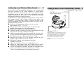
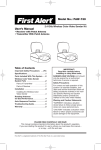
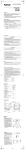
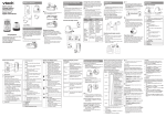
DENVER SC-2
2.4 GHz Wireless Baby Guard
User’s Manual
ALL RIGHTS RESERVED
COPY RIGHT DENVER ELECTRONICS A/S
www.denver.electronics.com
Please read all these safety and operating instructions completely.
Important Safety Precautions Before Setting Up
1
Congratulation on purchasing 2.4GHz Wireless Baby Guard.
Before operating your Wireless Baby Guard, please read all
these safety and operating instructions completely and then
retain for future reference.
●To prevent entanglement, never place the transmitter in crib or
playpen.
● Do not place the transmitter on any surface or mount it on any
wall where the transmitter or its AC adapter cord are within
reach of baby.
●Keep the transmitter and receiver out reach of children.
●Never use the transmitter or receiver near water. For example,
do not use near a bathtub, washbowl, laundry tub, kitchen sink,
in a wet basement. Etc.
●Disconnect the AC adapters from wall outlets during long
periods of nonuse.
●Position the transmitter, receiver and AC adapters to allow
adequate ventilation.
●Keep the transmitter out of direct sunlight.
●To prevent overheating, keep the transmitter, receiver and AC
adapters away from heat sources such as radiators, heat registers,
stoves or other appliances (including amplifiers) which produce
heat.
●Use only the adapters provided. Use of any others may
damage the transmitter and/or receiver.
● Plug into an electrical outlet with standard household power.
●Changes or modifications not approved by SELLER could
void user’s authority to operate the equipment.
●Do remember that you are using public airwaves when you
use the Wireless Baby Guard and that sound and video may be
broadcast to other 2.4GHz receiving devices. Conversations,
even from rooms near the transmitter, may be broadcast. To
protect the privacy of your home, always turn the transmitter off
when not in use.
If you have any questions
10
Symptoms
No power is
Supplied to the
Transmitter or
Receiver.
Check Points
● IS the power cord disconnected ?
- Connect it.
● Transmitter /Receiver is not turned on
- Slide the ON/OFF switch to the ON
position.
● Wrong AC adapter used.
- Use the AC adapter labeled output:
7.5V with the transmitter, 13.5V with
the receiver.
No sound or
Picture.
Noisy sound or
Picture.
● Channel switches are not the same
setting.
- Set the transmitter and the receiver to
same channel.
● Signal interfere due to microwave
oven .
- Turn off the oven or remove it from
path between transmitter and receiver.
● Signal interfere due to other signal
producing devices.
- Change the channel setting on both
the transmitter and the receiver.
- Identify and eliminate the source of
interference.
- Relocate the transmitter and /or
receiver.
● Out of range.
- Relocate the transmitter and /or
receiver.
● Improper antenna position.
- Adjust transmitter / receiver
antenna orientation.
What else can the Wireless Baby Guard do for you 9
Auto-sequence function
With the Wireless Guard, user’s can monitor a series of
rooms for maximum supervision of the home (or
office). The Wireless Baby Monitor can use up to four
transmitters on four different channels, while the
receiver can receiver signals on up to four different
frequencies and display them in sequence. The wireless
Baby Guard with four switches for four channels, when
two or three or four switches put down, two or three or
four channels display in sequence. Sequence interval
time, displays at eight second intervals.
CH1~ 4 channel switch: setting up the automatic
channel sequence function:
Setting down the channel switch that you wish to view,
setting up the channel switch that you wish to
deactivate.
Monitor to A/V function
The Wireless Baby Guard receiver unit has audio/video
outputs which can be sued to transfer the picture and
sound from the monitor screen to a TV screen. Connect
the outputs to the A/V input on a TV set for a large
screen display, or connect the outputs to a VCR to
record transmissions for later viewing.
Connect wire camera
The Wireless Baby Guard receiver unit can be
receive the picture and sound from the wire camera.
Connect the Video input and Audio input to wire
camera outputs, the unit can display the picture and
sound.
What You Get in This Package
2
The following elements should be included in the box.
Please check that you have them all before
installation.
● A transmitter with camera.
● A receiver with monitor.
● A 7.5V DC adapter for transmitter only.
● A 13.5V DC adapter for receiver only.
Warning: Two DC of adapters are included with the
Wireless Baby Guard. The DC adapters can not be
interchangeably used. Use the adapter labeled out
OUTPUT: 7.5V DC with the transmitter. USE the
adapter labeled OUTPUT: 13.5V DC with the
receiver.
Getting To Know Your Wireless Baby Monitor 3
Orienting Antennas for Optimal Performance 8
The Wireless Baby Guard Broadcasts its high-quality
audio and video using directional antennas which
mush be oriented in certain configurations for best
results. The 2.4 GHz audio/video antennas have been
designed to pivot and have limited rotation in either
clockwise or counter clockwise directions.
Warning:See instructions shown below for rotating
antennas. Rotation antennas beyond the specified
range will result in permanent damage to both
antennas and the mechanical stopper. Antenna does
not rotate over 270 degrees.
270
The automatic night Vision LEDS
allow the transmitter to see Your
baby even in a completely darkened room!
Note: The video image
displayed on he receiver
may appear “snowy”
when the transmitter is
operating in darkness or
very low levels of light.
Maximum rotation of audio/video
Antenna shown.
The transmitter can be wall mounted on the
wall mount bracket, or it can be easily
removed from the wall mount bracket for
placement on a flat surface, such as a table
top, dresser of shelf.
Note: The bracket does not rotate freely
360degrees.
Rear View
Front View
In most situations, the flat pitted face of the A/V
antennas on both the transmitter and receiver should be
facing one another. Since all rooms are different, for
optimal reception, additional slight pivots or rotations
may be necessary. If the transmitter and receiver are less
than 10 feet apart, keep the A/V antennas flat in their
casings.
Setting Up your Wireless Baby Guard
7
If you wish to wall mounting the transmitter, it is recommended
that the reception of the Video Monitor be tested before
installing the wall mount bracket. Have one adult hold the
transmitter against the wall at the selected mounting area while
another adult moves the receiver to a variety of locations
throughout the house to check reception.
If interference or other problems develop, please refer to check
the section of this User’s Guide titled “if you Have Any
Questions”. You may need to select a different location in the
room for mounting. The following steps show you how to set up
the Wireless Baby Guard:
● Make sure the transmitter and receiver are set to the
same channel. (CH1, 2, 3, or 4)
● Plug the jack on the 7.5V DC adapter cord into the DC
adapter socket on the back of the transmitter.
● Plug the DC adapter into a standard wall outlet.
● Slide the ON/OFF switch on the side of the transmitter to the
ON position. The power indicator will light.
● Adjust the angle and focus of the camera lens for best view
of baby. Point the microphone pick-up directly toward baby.
● Position the antenna so that it points to the ceiling.
● Plug the jack on the 13.5V DC adapter cord into the DC
adapter socket on the back of the receiver.
● Plug the AC adapter into a standard wall outlet.
Turn the receiver on.
● Adjust the volume switches to a comfortable level.
● Adjust the video image using the V-Hold (vertical hold),
Contrast and adjustment switch on the side of the receiver.
● Locate and orient the antennas on both the transmitter and
receiver according to the section of this User’s Guide
Titled “Orienting Antennas for Optimal Performance.”
GettingToKnowYourWirelessBabyMonitor 4
Transmitter-----Rear view
DC In
Power adapter plug
.
Channel 1 2 3 4
Channel selection. It is possible for the receiver
to pick up sounds or display interference from
other signal producing devices. To minimize
the potential for this problem, four channels
are available for use. Make sure that the
transmitter and receiver are set to the same
channel.
Receiver
5
Front
Receiver
View
6
Rear
Antenna
CH2 CH4
Power Switch
Volume
Led indicator
CH1 CH3 Audio indicator
Channel selection. It is
possible for the receiver
to pick-up sounds or display
interfere from other
signal producing devices.
To minimize this potential
problem, four channels
are available for use.
Make sure that the transmitter and receiver are set to the same channel.
1 2 3 4 5 6
①
②
③
④
⑤
⑥
DC 13.5V power adapter plug
Video output jack
Audio input jack
V-hold control
Bright Control
Contrast control
View
Specifications
Rx Description
Video System
Receiver Frequency
Max. Range (clear
line of sight)
Receiver Antenna
Receiver Sensitivity
Sound
Max. Output
The output 10%
Picture
Hor. Pull-in
+
Hor. Hold
+
Vert. Range
Linearity
V
H
Pincushion V/H
Barrel Dist V/H
Keystone Distortion
Scan Redisplay Rat
VH
Resolution at center
VH
Luminance Max
Current Consumption
Power Supply
11
Contents
I
NTSC
2.4GHz
300 feet
PAL
2.4GHz
300 feet
IMPROTANT SAFETY PRECAUTIONS BEFORE SETTING UP ------- 1
Directional
-25~ -90dBm
Directional
-25~ -90dBm
GETTING TO KNOW YOU WIRELESS BABY GUARD ------------------ 3
WHAT YOU GET IN THIS PACKAGE -----------------------------------------2
TRANSMITTER ------------------------------------------------------------------- 3
600mW
500mW
600mW
500mW
200Hz
200Hz
400Hz
400Hz
6 Hz
15%
15%
3%
3%
3%
90%
90%
250 lines
300 lines
100 cd/m2
1000 mA
DC 13.5V
200Hz
200Hz
400Hz
400Hz
6 Hz
15%
15%
3%
3%
3%
90%
90%
250 lines
300 lines
100 cd/m2
1000 mA
DC 13.5V
RECEIVER ------------------------------------------------------------------------- 5
SETTING UP YOUR WIRELESS BABY GUARD -------------------------- 7
ORIENTING ANTENNAS FOR OPTIMAL PERFORMANCE ----------- 8
WHAT ELSE CAN THE WIRELESS BABY GUARD DO FOR YOU -- 9
AUTO-SEQUENCE FUNCTION ---------------------------------------------- 9
MONITOR TO A/V FUNCTION ---------------------------------------------- 10
IF YOU HAVE ANY QUESTIONS -------------------------------------------- 11
SPECIFICATIONS --------------------------------------------------------------- 12
Specifications
TX Description
Video System
Transmitter Frequency
Max. Range (clear line
of sight)
Transmitter Antenna
Transmitter Sensitivity
Number of Effective
Pixels
Picture of color
Optical Size
Scanning system
Resolution (TV line)
Auto Exposure
Camera Correction
Backlight
Compensation
Indoor /outdoor
Night – time
MIC. Sensitivity
Aux. Input
White Balance
Number of Channels
Current Consumption
Power Supply
12
NTSC
2.4GHz
300 feet
PAL
2.4GHz
300 feet
Directional
Directional
10dBm CE
0dBm
352×288
FCC
320×240
B/W 1/3”
2:1 interlace
240 (h)
1/60 – 1/6000 sec.
Auto
Indoor only
1 to 2 m
2 -3meters
1×video, 2×audio
auto
4
500mA
DC 7.5V