1
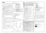
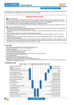
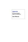
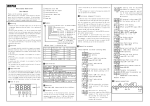
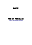
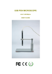
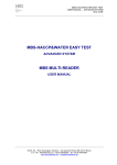
→ PV DC 30V/3A COS¢=1 Alarm O U T 1 O U T 2 / AL1 AT/M AL2 SET /M ↑ ↑ ⑤ ⑥ T/C ⑦ S 0~1600℃ E 0~1000℃ Rt Pt100 Cu50 -199~600℃ -50~150℃ mV mV mA mA + F ↑ C B 9:96H × 96W TA series of temperature controller >> /M Confirm Modify SET Shift and flashes Stop flashing ↑ E G H In Manual operation/Non-autotune estate, press and hold / key for more than 3 seconds to enter/quit the below >> E:24VDC or 18-30V AC/DC Sizes: 4:48H × 48W 6:48H × 96W 7:72H × 72W 8:96H × 48W Measured displaying Set displaying ↓ ↑ S:SSR/Logic T:SCR Power supply:Default:90-260V AC/DC Input up limit ↓ 3S + + D + Input type ↓ 3S A Mounting and Sizes ↑ Displays temperature unit Input low limit menu for display range settings. ↓ Input signals:Default: K,J,T,S,Pt100/mA,lN -T:SCR N:Non OUT1: I:4-20mA R:RELAY ↓ 3S 0-75mV 35~85%RH ≤ 350g Environment humidity Weight ⑦.Down key AL1:R:RELAY S:SSR/Logic T:SCR Power on 4-20mA /0-10V Withstand voltage strength 1500V Rms (Between power terminal and the housing) Insulation resistance Min 50M Ω(500V DC)(Between power terminal and the housing) Environment temperature 0~50℃ -10~60℃ Save temperature Models TD □□ - □□□□ autotuning estate.Press again to quite. Self-check All LED on AT lamp off. ⑥.Up key In display estate,press SET and <</M key at the same time until AT/M lamp flahses.Then ithe instrument is under ↑ ⑤.Shift/Autotune key Press this key to shift digit of parameter value setting. Or hold this key for more than 3 seconds can enter/quit autotune estate. When enter autotune estate, AT lamp on. When quit autotune estate, 0~999℃/0~1200℃ 0~999℃ /0~1200℃ -150~400℃ (Special order) impossible. ☆ Antotuning operation. >> ①. PV / parameter symbols ②. SV / parameters preset value ③. Indication lamps OUT1: Heating/Main control output lamp On: Output Off: No output OUT2/AL2: Colling/Alarm 2 output lamp On: Output Off: No output AT/M: On: manual operation Off: auto operation Flash: under autotuning estate P/MV: SV/MV display setting On: MV manual output Off: SV setting AL1: Alarm 1 lamp On: Alarm Off: No Alarm AL2: Alarm 21 lamp On: Alarm Off: No Alarm ④.Set key Parameter Setting/Changing Input K J T and key to modify the numerals; D: Press SET key to confirm. ☆ In autotuning estate,output value modification is >> → → P/MV RELAY: normal open AC 250V/3A DC 30V/3A COS¢=1 SSR/LOGIC:24V DC12V/ 30mA ↑ ↑ TA series of temperature controller is available for many TC or RTD input, adopt some advanced techonology such multi digital filter circuit, autotune PID, fuzzy PID that make it is very precise, stable, strong anti-interference and simple operation. The instrument is widely applied to AC 250V/3A SSR/LOGIC :24V DC ± 2V/ 20mA OUT2/AL2: R:RELAY S:SSR/Logic Applications RELAY:normal open Main output SV → operation & input connect do MV settable. B: Press the << / M key to select the digit you want to modify; C: Press ≤ 300ms ↑ This instrument should be installed in a domestic environment. Otherwires electricla shock, fire or malfunction may result. To avoid using this instrument in environment full of dust or caustic gas. To avoid using this instrument in environment of strong shock or concussion. To avoid using this instrument in environment of overflow water or explosive oil. The power supply wire should not put together with large current wire to aviod electromagnetic radiation, If it must to put together, we suggest to use a individual pipe. In case the instrument is used in environment of strong noise, (such as motor, transformer, solenoid, etc.) A current suppresser or noise filter should be used. 0.3%F.S ± 2digit ↑ Caution ④ -199~1800℃ Accuracy Sampling cycle >> Please do not turn on the power supply until all of the wiring is completed. Otherwise electrical shock, fire or malfunction may result. Do not wire when the power is on. Do not turn on the power supply when cleaning this instrument. Do not disassemble, repair or modify the instrument. This may cause electrical shock, fire or malfunction.Use this instrument in the scope of its specifications. Otherwise fire or malfunction may result.The use life of the output relay is quite different according to is capacity and condictions. If use out of its scope, fire or malfunction may result. ③ Display range while off means MV manual output setting,but only on manual ↓ ② Warning ≤ 5VA ↑ ① A: In display estate,press SET,P/MV lamp on means SV setting, Consumption >> Panel Parameter Setting &Autotuning ☆ Parameters setting: 90-260V AC/DC 50/60Hz Power supply >> Thanks a lot for selecting the product! Before operating this instrument, please carefully read this manual and fully understand its contents. If any probroms, please contact our sales or distributors whom you buy from. This manual is subject to change without prior notice. Specifications ↑ Instruction Manual >> TD Series Temperature Controller automation systems of mechanism, chemical industrial, chinaware, light industrial, metallurgy and petroleum chemical industrial. It is also applied to the production line of foodstuff, packing, printing, dry machine, metal heat process equipment to control the temperature. >> MYPIN Low limit value, it is adjustable Sizes Model A B C D E F G H TD4 44.5+0.5 45+0.5 65 65 48 48 8 80 TD6 43.5+0.5 91+0.5 65 115 48 96 12 80 TD7 91+0.5 91+0.5 115 115 96 96 12 100 TD8 91+0.5 43.5+0.5 65 115 96 48 12 80 TD9 67.5+0.5 67.5+0.5 95 95 72 72 12 100 ↓ by the input signal. SET Up limit value, it is adjustable by the input signal. ↓ SET AL1 hysteresis setting value. Range ± 90, factory setting 1.0 ↓ SET 1 SET AL2 mode: The same as AL1. SET Range: ± 100.Display value PV = Measured value - PVF SET Proportional band (%) range 0.1-3600. If P=OFF, it means ON/OFF control SET Integral time range 0.1-3600. I=OFF means 4 ↓ cancel integral time. N0 17 18 9 TD7 AL1 means unlocked. LcK=010 means locked. Note: T1 means autotuning. T2 G 6 ▲ 8 + 6 SSR 7 - 13 2 14 3 15 4 16 5 17 6 18 7 19 8 20 N0 OUT1 Mamual/Auto Convertion: In display estate,press <</M to shift. AT/M lamp on means manual operation, while off com 1 NC + 6 B For the very first time, please press SET and <</M key 4-20mA 9 TC 2 1 RTD 8 until AT/M lamp flash to enter autotuning estate.In the 22 10 future,if the load/control temp. point changes in small 23 A 11 scale (eg. Running the same equipment, and the preset TD6/TD8/TD9 are subject to the 24 12 value changes within ± 30℃), the user no need to let it drawing on the product. B autotuning again. Because the instrument has recorded the ON/OFF control: ▲ Set value previous PID parameters. When the instrument is used for ON Cooling OFF huge capacity heating equipments, the user should set Heating ON HYS OFF ▲ LO HI autotuning value lower 5%-10% than the normal control ▲ LO HI Alarm mode:▲ Set value △ Alarm value AL value, in order to decrease the exceed-tuning caused by control. OFF ON HY 0 :Deviation HI Normally, the control cycle of the heating equipment ▲ △ alarm LO HI should be 20-30 seconds. For huge capacity heating O N OFF HY 1:Deviatian LO alarm equipments, the value should be 30-120 seconds, in order to ▲ HI LO △ longer the use life of the relay. For non-contact output, such as SSR control output, the value should be 1-3. O N OFF ← ↑ ↑← ↑← ↑← HY SET Terminal configurations (If any changed, please refer to the product showing.) B 1 7 cancel derivative time. ↓ SET 90~260V/AC Control directions: HEAt: heating COOL: cooling Control hysteresis, range: ± 100. It is not available when P ≠ OFF 2 SSR 0UT1 4 RELAY 4 AL1 The output control mode ,RELAY=020, SSR\SCR=001,4-20mA=000. 3 + 3 4-20 mA ↓ SET SET 8 Parameter lock code setting. LcK=000 Derivative time range 0.1-3600. D=OFF means ↓ RELAY N C ↓ TC/m V ↓ 16 ↑ SET Input signal selection TC: K, J, E, S RTD: Pt100, Cu50 The factory setting is K ↓ G 15 7 OUT1 SET TD4 5 6 + SSR - ← ← ↓ T2 7 9 6 90-260V AC ↑ ↓ ▲ B + RTD 2:Absolute value HI alarm LO ▲ HY ↑← O N 3: Absolute value LO alarm 8 LO △ O N A △ B + 11 11 AL2 12 5: Section inside alarm 12 SSR - OFF ▲ ON HI OFF ▲ HI O N OFF 4: Section outside alarm 9 10 △ △ HI OFF △ ▲ △ HI Note: All the factory setting value of deviation alarm is 1.0. FUSE R J C 1 2 3 4 5 6 7 8 9 Power supply OUT1 10 11 12 13 14 15 16 NC NO 17 18 Pt AL1 J-1 Heating cord SET T1 5 13 14 1.Relay output control (forTA9) equipment ↓ - 7 8 12 B Heating ① =tPV 4-20mA, F means F degree. SET AL1 mode: 0: Deviation HI alarm 1: Deviatian AL2 set range: –1999-9999. =PID,control; transmit; Temperature unit. C means C degree, AL1 set range: –1999-9999 ↓ SET SSR 4 RELAY 4 RTD 11 RTD ↓SET HOLD SET >3 S alarm 5: Section inside alarm 6: TC broken alarm ,The factory setting is 2 + Only for 4-20mA ------------------------------------------ LO alarm 2: Absolute value HI alarm 3: Absolute value LO alarm 4: Section outside - SET 3 AL1 Application examples A 90-260V DC/AC ↓ SSR 4-20mA 0: No decimal 1: One decimal (when analogue is active) 3 OUT2/AL2 High analogue output Password setting. Factory setting 015 ↓ + TC - ↓SET ↓ 2 ↓ SET Decimal point setting: 10 90-260V AC/DC ← ← ↓SET 1 High analogue output (when analogue is active) + AL2 hysteresis setting value. Range ± 90, factory setting 1.0 Malfunction estimate ① No Display : Check all the connection and wiring if it is all correct. Specially pay attention to the power supply terminals and signal input ternimals. ② Incorrect Didplay: Check if the input signal is conformity with the selected symbol. For TC input, please use the relative compensation cable. For RTD input, please use low impedence cable. The 3 wires should at the same length. If all above mentioned is collect , pleaase use parameter PVF to modify. ③ Incorrect Control : If the instrument has been used for a long time, the user find the temperature is hard to rise up to the set value, meanwhile the outsidesystem running well, there must be something wrong with the parameters of the instrument. The user need to re-autotuning the instrument. If the instrument lost control, please check if the connection of the control is correct. If external load is shorted, broken, wrong connection or components is damaged, it will cause lost control as well. When it is necessary, please push out the PCB to check the if the output terminals is damaged and not available. ④ Display malfunction : “UUUU”: The input signal exeed the measured HI range . 2