1
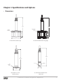
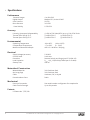
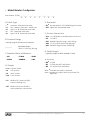
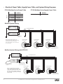
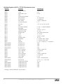
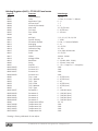
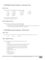
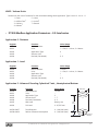
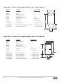
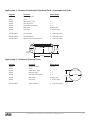
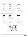
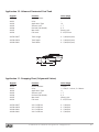
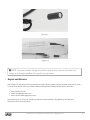
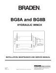
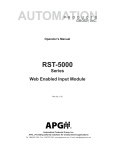
PT-500 Modbus Series User Manual APG R Doc #9003999 Rev A, 02/15 Table of Contents Introduction................................................................................................................. iii Warranty and Warranty Restrictions..................................................................... iv Chapter 1: Specifications and Options..................................................................... 1 Dimensions.........................................................................................................................................1 Specifications.................................................................................................................................... 2 Model Number Configurator........................................................................................................... 3 Electrical Pinout Table, Power Supply Table, and System Wiring Diagrams..................... 4 Chapter 2: Installation and Removal Procedures and Notes...............................5 Tools Needed...................................................................................................................................... 5 Mounting Instructions.................................................................................................................... 5 Electrical Installation...................................................................................................................... 5 Removal Instructions...................................................................................................................... 6 Chapter 3: Programming.............................................................................................6 Modbus Programming..................................................................................................................... 6 Modbus Programming with RST-6001 and APG Modbus Software....................................... 6 PT-500 Modbus Register Lists................................................................................................... 7-9 PT-500 Modbus Sensor Parameters - L5 pressure series....................................................... 10 PT-500 Modbus Sensor Parameters - L31 level series............................................................ 10 PT-500 Modbus Application Parameters - L31 level series.............................................. 11-15 Chapter 4: Maintenance............................................................................................ 16 General Care..................................................................................................................................... 16 Vent Tube Drying....................................................................................................................... 16-17 Repair and Returns......................................................................................................................... 17 NOTE: Wiring information in this User Manual is specific to the Modbus Series of the PT-500. If you have a 0-5V, mV/V, or 4-20 mA Series sensor, please consult the factory at 1-888-525-7300, or our website at www.apgsensors.com/support, for the appropriate manual for your sensor. ii Tel: 1/888/525-7300 • Fax: 1/435/753-7490 • www.apgsensors.com • [email protected] Introduction Thank you for purchasing a PT-500 modbus series submersible pressure transmitter from APG. We appreciate your business! Please take a few minutes to familiarize yourself with your PT-500 and this manual. PT-500 submersible pressure transmitters offer reliability in harsh industrial conditions. The small size, integrated electronics, wide operating temperature range, and durability make the PT-500 the perfect instrument for static and dynamic pressure measurement. Reading your label Every APG instrument comes with a label that includes the instrument’s model number, part number, serial number, and a wiring pinout table. Please ensure that the part number and pinout table on your label match your order. Tel: 1/888/525-7300 • Fax: 1/435/753-7490 • www.apgsensors.com • [email protected] iii Warranty and Warranty Restrictions APG warrants its products to be free from defects of material and workmanship and will, without charge, replace or repair any equipment found defective upon inspection at its factory, provided the equipment has been returned, transportation prepaid, within 24 months from date of shipment from factory. THE FOREGOING WARRANTY IS IN LIEU OF AND EXCLUDES ALL OTHER WARRANTIES NOT EXPRESSLY SET FORTH HEREIN, WHETHER EXPRESSED OR IMPLIED BY OPERATION OF LAW OR OTHERWISE INCLUDING BUT NOT LIMITED TO ANY IMPLIED WARRANTIES OF MERCHANTABILITY OR FITNESS FOR A PARTICULAR PURPOSE. No representation or warranty, express or implied, made by any sales representative, distributor, or other agent or representative of APG which is not specifically set forth herein shall be binding upon APG. APG shall not be liable for any incidental or consequential damages, losses or expenses directly or indirectly arising from the sale, handling, improper application or use of the goods or from any other cause relating thereto and APG’s liability hereunder, in any case, is expressly limited to the repair or replacement (at APG’s option) of goods. Warranty is specifically at the factory. Any on site service will be provided at the sole expense of the Purchaser at standard field service rates. All associated equipment must be protected by properly rated electronic/electrical protection devices. APG shall not be liable for any damage due to improper engineering or installation by the Purchaser or third parties. Proper installation, operation and maintenance of the product becomes the responsibility of the user upon receipt of the product. Returns and allowances must be authorized by APG in advance. APG will assign a Return Material Authorization (RMA) number which must appear on all related papers and the outside of the shipping carton. All returns are subject to the final review by APG. Returns are subject to restocking charges as determined by APG’s “Credit Return Policy”. iv Tel: 1/888/525-7300 • Fax: 1/435/753-7490 • www.apgsensors.com • [email protected] Chapter 1: Specifications and Options • Dimensions 7.14" [181.3mm] 7.40” [187.9mm] NON-REMOVABLE SENSOR CAGE ASSEMBLY REMOVABLE SENSOR CAGE ASSEMBLY 2.00" [50.8] 2.24” [56.9mm] ø3.50" ø3.50” [88.9mm] [88.9mm] PT-500 with Reusable Cage PT-500 with Welded Anti-snag Cage 6.44" [163.5mm] 5.29" [134.4mm] PROTECTIVE CONE ø.188 THRU 1 1/2" SANITARY FITTING ø1.00" [25.4mm] ø1.98" [50.3mm] PT-500 with Tri-clover Sanitary Fitting PT-500 with Removable Plastic Nose Cone Tel: 1/888/525-7300 • Fax: 1/435/753-7490 • www.apgsensors.com • [email protected] 1 • Specifications Performance Pressure Ranges 0 to 300 PSIG Digital Output Modbus RTU, 4-wire RS-485 Over Pressure 2X FSO Burst Pressure 3.0X FSO 1 Year Stability0.75% FSO Accuracy Linearity, Hystereses & Repeatability Thermal Zero Shift @ 70 °F Thermal Span Shift @ 70 °F ±0.25% of Full Scale (BFSL) up to ±0.1% of Full Scale ±0.045% FSO/°C (±0.025% FSO/°F) ±0.045% FSO/°C (±0.025% FSO/°F) Environmental Operating Temperature Compensated Temperature Maximum Submersible Depth -40 to 85°C (-40 to 185°F) -17 to 54°C (0 - 130°F) 462.2 ft / 140.88 m / 300 psig Electrical Supply Voltage (at sensor) 5-28 VDC Current Draw 2 mA max. Protection Reverse Polarity and Surge (per IEC 61000-4-5) Load LimitationR(max) = ((Vs-12V)/0.02A)-(0.042Ω per ft. of cable) Startup Time 200 ms Materials of Construction Wetted Materials 316L Stainless Steel Anti-snag Cage 316L Stainless Steel Cable Urethane, PVC, or Hytrel Protective Nose ConeDelrin Mechanical Pressure Connection Cable Tensile Strength See model number configurator for complete list Up to 200 pounds Patents 2 US Patent No. 7,787,330 Tel: 1/888/525-7300 • Fax: 1/435/753-7490 • www.apgsensors.com • [email protected] • Model Number Configurator Part Number: PT-500_____ - _____ - _____ - _____ - _____ - _____ - _____ - _____ A B C D E F G H A. Cable Type E. Overmold □ -▲ Urethane - Blue (with vent tube) □ A PVC - Black (no vent tube - sealed unit) □B Hytrel .31” Ø - Black (with vent tube) □C PVC - Black (with vent tube) □ D Hytrel .25” Ø - Black (with vent tube) □ E0▲ No overmold for 1/2” NPTM fitting for conduit □ E37 Pigtail with overmolded cable B. Pressure Range □ Specify range in desired unit of measure __________ Max Water Depth 462.2 ft. (140.9 m), 300 psig C. Standard Units of Measure □ PSI □ FTH2O □ INWC □ INH2O □ MMH2O □ FWC F. Process Connection □ P1▲ □ P5 □ P37 □ P38 □ P39 1/2” NPTM with removable plastic nose cone 1/4” NPTF Welded Cage (anti-snag 1 piece fitting) 1-1/2” tri-clover with 3/4” diaphragm Reusable Cage (includes P38 fitting) G. Cable Length □ (specify length of cable needed in feet) H. Accuracy □ N0▲ ±0.25% □ N1 ±0.25% with NIST certification □ N2 ±0.1% with NIST certification D. Output □ L1▲ □ L3 □ L9 □ L10 4-20 mA, 2-wire 0-5V, 4-wire* mV/V, 4-wire* 0-10V, 4-wire* □ L5 □ L31 Modbus RTU, 4-wire RS-485* Pressure reading only Note: ▲Indicates this option is standard. Note: *Indicates this option does not yet have CSA Approvals. Modbu RTU, 4-wire RS-485* Level calculations, tank volume Tel: 1/888/525-7300 • Fax: 1/435/753-7490 • www.apgsensors.com • [email protected] 3 • Electrical Pinout Table, Supply Power Table, and System Wiring Diagrams PT-500 Modbus Series Supply Power Table PT-500 Modbus Series Pinout Table Pigtail Modbus Red + Power Black - Power Green B (TX-) White A (TX+) Shield Case Gnd Modbus Power Supply 5-28 VDC Modbus System Wiring Power Supply +5-28 Vdc Master Device RS-485 A (TX+) Use Shielded Cable GND RS-485 B (TX-) 120 Ω terminating resistor Note: PT-500 modbus sensors use reversed TX+/TX- pins. When connecting to your system, ensure continuity of TX- to TX- and TX+ to TX+, rather than A to A and B to B. PT-500 modbus series sensor PT-500 modbus series sensor Sensor 1 Sensor 2 V+ V+ PT-500 modbus series sensor Sensor 3 V+ B (TX-) A (TX+) B (TX-) A (TX+) B (TX-) A (TX+) GND GND GND 120 Ω terminating resistor at last sensor Modbus System Wiring with RST-6001 Power Supply RST-6001 Modbus Controller USB to computer with APG Modbus software +5-28 Vdc A B -5V +5V Equivalent 120 Ω terminating resistor internal to RST-6001 Note: An independent +5-28 Vdc power supply is required when using an RST-6001 Modbus Controller. The RST-6001 can only supply ±5 Vdc, not the +5-28 Vdc required by the modbus series PT-500. 4 Use Shielded Cable GND PT-500 modbus series sensor PT-500 modbus series sensor PT-500 modbus series sensor Sensor 1 Sensor 2 Sensor 3 V+ V+ V+ B A B A B A GND GND GND Tel: 1/888/525-7300 • Fax: 1/435/753-7490 • www.apgsensors.com • [email protected] 120 Ω terminating resistor at last sensor Chapter 2: Installation and Removal Procedures and Notes • Tools Needed • Wrench sized appropriately for your PT-500’s process or conduit connection. • Thread tape or sealant compound for threaded connections. • Mounting Instructions Your PT-500 can be mounted in three ways: via NPT process connection, free-hanging suspension, or conduit mounted. Mounting your pressure transducer is easy if you follow a few simple steps: • Never over-tighten the sensor. In all cases, tighten the sensor as little as possible to create an adequate seal. • Always use thread tape or sealant compound on tapered threads. Wrap thread tape in the opposite direction of the threads so it does not unravel as you screw the sensor into place. Unraveling can cause uneven distribution and seal failure. • Always start screwing in your sensor by hand to avoid cross-threading. Thread failure can be a problem if you damage threads by over-tightening them or by crossing threads. • For suspension mounting the PT-500, drill a 3/16” hole into the 1/2” NPTF to 1/2” NPTF hex coupler (P/N 511414) and secure it to the 1/2” NPTM coupler fitting of the PT-500. Attach a .060” diameter 316L SS cable of desired length to the hex coupler and secure the steel cable according to your application requirements. NOTE: If your PT-500 has a vent tube, do not seal, cover, or close the vent tube with anything other than an APG-provided venting cap or desiccant drying cartridge (See Figure 4.1 and 4.2). Unapproved seals or covers will prevent proper sensor operation. • Electrical Installation • Attach the wires of your PT-500 to your control system according to the pinout table above. IMPORTANT: APG modbus equipment uses reversed TX+/TX- pins. When making connections between APG equipment, ensure continuity of A to A and B to B pins. When connecting APG modbus equipment to other systems, ensure continuity of TX+ to TX+ and TX- to TX-. Tel: 1/888/525-7300 • Fax: 1/435/753-7490 • www.apgsensors.com • [email protected] 5 • Removal Instructions Removing your PT-500 from service must be done with care. It’s easy to create an unsafe situation, or damage your sensor, if you are not careful to follow these guidelines: • For sensors installed via NPT process connection, make sure the pressure is completely removed from the line or vessel. Follow any and all procedures for safely isolating any media contained inside the line or vessel. • Remove the sensor with an appropriately sized wrench (per your process connection). • For suspended sensors, retrieve the sensor from the vessel. Follow any and all procedures for safely isolating any media contained inside the line or vessel. • Carefully clean the sensor’s fitting and diaphragm of any debris (see General Care) and inspect for damage. • Store your sensor in a dry place, at a temperature between -40° F and 180° F. DANGER: Removing your process connected PT-500 Pressure Transmitter while there is still pressure in the line could result in injury or death. IMPORTANT: Any contact with the diaphragm can permanently damage the sensor. Use extreme caution. Chapter 3: Programming • Modbus Programming PT-500 L5/L31 modbus series sensors use standard Modbus RTU protocol (RS-485). The sensors can only operate as slave devices. Sensor default transmission settings are 9600 Baud, 8 Bits, 1 Stop Bit, No Parity, and require a minimum delay of 300 ms between transactions to return the contents of all registers. Commands returning fewer registers will require shorter delays. See PT-500 Modbus Register Lists on pages 7 - 9. NOTE: For more information about Modbus RTU, please visit www.modbus.org. 6 Tel: 1/888/525-7300 • Fax: 1/435/753-7490 • www.apgsensors.com • [email protected] • Modbus Programming with RST-6001 and APG Modbus Software APG RST-6001 Modbus Controller can be used in tandem with APG Modbus to program and control up to 20 PT-500 L5 or PT-500 L31 sensors. Through APG Modbus, you can monitor the raw readings from the sensor, including level or pressure, temperature and battery voltage, or configure the sensor. See PT-500 Modbus Register Lists on pages 7 - 9. NOTE: For APG Modbus programming instructions, or to download APG Modbus software, please visit www.apgsensors.com/support. • PT-500 Modbus Register Lists Input Registers (0x04) Register Returned Data 30299 Model Type 30300 Pressure (L5 - PSI; L31 - mmH2O) 30301N/A 30302 Temperature Reading (in 0C, signed) 30303-30304 Calculated (raw) 30305-30306 N/A 30307N/A 30308 Battery Voltage 30309 Trip 1 Status 30310 Trip 2 Status NOTE: The Calculated Readings will be returned without a decimal place. In order to obtain the true result, the Decimal Place setting must be taken into account. Tel: 1/888/525-7300 • Fax: 1/435/753-7490 • www.apgsensors.com • [email protected] 7 Holding Registers (0x03) - PT-500 L5 pressure series Register 40400 40401 40402 40403 40404 40405 40406 40407 40408 40409 40410 40411 40412 40413 40414 40415 40416 40417 40418 40419 40420 40421 40422-40423 40424-40425 40426-40427 40428-40429 40430 40431 40432 40433 40434 40435 40436-40437 40438-40439 40446 40447-40448 40449-40450 40451-40452 40453-40454 FunctionValue Range Device Address 1 to 247 Units 0-16 Application Type 0 or 8 N/A Decimal (Calculated) 0-3 Max Pressure *0 - 32,000 PSI Full Pressure 0 - 32,000 PSI Zero Offset -15,000 - 30,000 PSI Pressure Decimal 0-3 A/D Gain *1, 2, 4, 8, 16, 32, 64, 128 N/A Parameter Default 0 = No; 1 = Restore Defaults Averaging 0 - 10 Calibration Value *-32,767 - 32,767 Calibration Flag *0 - 300 Sample Rate 10 to 1000 milliseconds Scale *0 - 65,535 Offset -20,000 - 20,000 Voltage Offset -20 - 20 Baud Rate 0 - 3 (2400, 9600, 19200) Parity 0 - 2 (none, even, odd) Stop Bit 0 - 1 (0 = 1 stop bit; 1 = 2 stop bits) Pressure X^3 *N/A Pressure X^2 *N/A Pressure X^1 *N/A Pressure X^0 *N/A Trip 1 Pressure -15,000 - 30,000 PSI Trip 1 Window 0 - 30,00 PSI Trip 1 Type 0 - 29 Trip 2 Pressure -15,000 - 30,000 PSI Trip 2 Window 0 - 30,00 PSI Trip 2 Type 0 - 29 Multiplier 0.0010 - 99.9999 (float) Description A - Z, 0 - 9, /.-,+* (16 char) Temperature Offset -20 - 20 Temperature X^3 *N/A Temperature X^2 *N/A Temperature X^1 *N/A Temperature X^0 *N/A *Setting is factory calibrated. Do not adjust. 8 Tel: 1/888/525-7300 • Fax: 1/435/753-7490 • www.apgsensors.com • [email protected] Holding Registers (0x03) - PT-500 L31 level series Register 40400 40401 40402 40403 40404 40405 40406 40407 40408 40409 40410 40411 40412 40413 40414 40415 40416 40417 40418 40419 40420 40421 40422-40423 40424-40425 40426-40427 40428-40429 40430 40431 40432 40433 40434 40435 40436-40437 40438-40439 40440-40441 40442-40443 40444-40445 40446 40447-40448 40449-40450 40451-40452 40453-40454 FunctionValue Range Device Address 1 to 247 Units 1 = Feet, 2 = Inches, 3 = Meters Application Type 0 - 11 Volume Units 1-7 Decimal (Calculated) 0-3 Max Level *0 - 65,535 mm Full Level 0 - 65,535 mm Zero Offset 0 - 610 mm N/A A/D Gain *1, 2, 4, 8, 16, 32, 64, 128 Specific Gravity 1 - 2,000 Parameter Default 0 = No; 1 = Restore Defaults Averaging 0 - 10 Calibration Value *0 - 65,535 Calibration Flag *0 - 300 Sample Rate 10 to 1000 milliseconds Scale *0 - 65,535 Offset -20,000 - 20,000 Voltage Offset -20 - 20 Baud Rate 0 - 3 (2400, 9600, 19200) Parity 0 - 2 (none, even, odd) Stop Bit 0 - 1 (0 = 1 stop bit; 1 = 2 stop bits) Pressure X^3 *N/A Pressure X^2 *N/A Pressure X^1 *N/A Pressure X^0 *N/A Trip 1 Level 0 - 65,535 (mm) Trip 1 Window 0 - 65,535 (mm) Trip 1 Type 0 - 29 Trip 2 Level 0 - 65,535 (mm) Trip 2 Window 0 - 65,535 (mm) Trip 2 Type 0 - 29 Parameter 1 0 - 1,000,000 (mm) Parameter 2 0 - 1,000,000 (mm) Parameter 3 0 - 1,000,000 (mm) Parameter 4 0 - 1,000,000 (mm) Parameter 5 0 - 1,000,000 (mm) Temperature Offset -20 - 20 Temperature X^3 *N/A Temperature X^2 *N/A Temperature X^1 *N/A Temperature X^0 *N/A *Setting is factory calibrated. Do not adjust. Tel: 1/888/525-7300 • Fax: 1/435/753-7490 • www.apgsensors.com • [email protected] 9 • PT-500 Modbus Sensor Parameters - L5 pressure series 40401 - Units Determines the units of measure for the calculated reading. 0 = PSI 5 = mmH2O† 10 = mmHG‡ 1 = BAR 6 = cmH2O† 11 = cmHG‡ † 2 = mBAR 7 = mH2O 12 = inHG‡ 3 = kPa 8 = inH2O† 13 = kg/cm2 † 4 = MPa 9 = ftH2O † ‡ 14 = inSW 15 = inSW 16 = mSW All H2O pressure measurements @ 20° C. All HG pressure measurements @ 0° C. 40402 - Application Type Determines the units of measure for the calculated reading. 0 = Standard (units selected in 40401 are displayed) 8 = Custom (units selected in 40401 and multiplier in 40436-40437 are used to compute desired units; description in 40438-40439 is label for measurement) • PT-500 Modbus Sensor Parameters - L31 level series 40401 - Units Determines the units of measure for the calculated reading when Application Type is set to 0, 1, or 7. 1 = Feet 2 = Inches 3 = Meters 40402 - Application Type Determines the type of calculated reading performed by the sensor. 0 = Distance 1 = Level 2 = Standing Cylindrical Tank with or without Hemispherical Bottom 3 = Standing Cylindrical Tank with or without Conical Bottom 4 = Standing Rectangular Tank with or without Chute Bottom 5 = Horizontal Cylindrical Tank with or without Spherical Ends 6 = Spherical Tank 7 = Pounds (Linear Scaling) 8 = N/A 9 = Vertical Oval Tank 10 = Horizontal Oval Tank 11 = Strapping Chart 10 Tel: 1/888/525-7300 • Fax: 1/435/753-7490 • www.apgsensors.com • [email protected] 40403 - Volume Units Determines the units of measure for the calculated reading when Application Type is set to 2 - 6 or 9 -11. 1 = Feet3 5 = Liters 3 2 = Million Feet 6 = Inches3 3 = Gallons 7 = Barrels 3 4 = Meters • PT-500 Modbus Application Parameters - L31 level series Application 0 - Distance Register 40400 40401 40402 40403 40404 FunctionValue Range Device Address 1 to 247 Units 1 = Feet, 2 = Inches, 3 = Meters Application Type 0 Volume Units -Decimal (Calculated) 0-3 Application 1 - Level Register 40400 40401 40402 40403 40404 FunctionValue Range Device Address 1 to 247 Units 1 = Feet, 2 = Inches, 3 = Meters Application Type 1 Volume Units -Decimal (Calculated) 0-3 Application 2 - Volume of Standing Cylindrical Tank ± Hemispherical Bottom Register 40400 40401 40402 40403 40404 40405 40406 FunctionValue Range Device Address 1 to 247 Units -- Application Type 2 Volume Units 1-7 Decimal (Calculated) 0-3 Max Level (factory set) Full Level 0 - 65,535 mm 40436-40437 40438-40439 Tank Diameter Radius of Bottom Hemisphere 0 - 1,000,000 (mm) 0 - 1,000,000 (mm) Tel: 1/888/525-7300 • Fax: 1/435/753-7490 • www.apgsensors.com • [email protected] Diameter Full Level or Bottom Radius 11 Application 3 - Volume of Standing Cylindrical Tank ± Conical Bottom Register 40400 40401 40402 40403 40404 40405 40406 FunctionValue Range Device Address 1 to 247 Units -- Application Type 3 Volume Units 1-7 Decimal (Calculated) 0-3 Max Level (factory set) Full Level 0 - 65,535 mm 40436-40437 40438-40439 40440-40441 Tank Diameter Cone Diameter(at bottom of cone) Length (height) of Cone Diameter Full Level 0 - 1,000,000 (mm) 0 - 1,000,000 (mm) 0 - 1,000,000 (mm) Cone Length Cone Diameter Application 4 - Volume of Standing Rectangular Tank ± Chute Bottom 12 Register 40400 40401 40402 40403 40404 40405 40406 Function Device Address Units Application Type Volume Units Decimal (Calculated) Max Level Full Level Value Range 1 to 247 -- 4 1-7 0-3 (factory set) 0 - 65,535 mm 40436-40437 40438-40439 40440-40441 40442-40443 40444-40445 Tank X Dimension Tank Y Dimension Chute X Dimension Chute Y Dimension Length (height) of Chute 0 - 1,000,000 (mm) 0 - 1,000,000 (mm) 0 - 1,000,000 (mm) 0 - 1,000,000 (mm) 0 - 1,000,000 (mm) Full Level Tank X Tank Y or Tel: 1/888/525-7300 • Fax: 1/435/753-7490 • www.apgsensors.com • [email protected] Chute Length Chute X Chute Y Application 5 - Volume of Horizontal Cylindrical Tank ± Hemispherical Ends Register 40400 40401 40402 40403 40404 40405 40406 FunctionValue Range Device Address 1 to 247 Units -- Application Type 5 Volume Units 1-7 Decimal (Calculated) 0-3 Max Level (factory set) Full Level 0 - 65,535 mm 40436-40437 40438-40439 40440-40441 Tank Length Tank Diameter Radius of End Hemispheres Diameter 0 - 1,000,000 (mm) 0 - 1,000,000 (mm) 0 - 1,000,000 (mm) Full Level End Radius Length Application 6 - Volume of Spherical Tank Register 40400 40401 40402 40403 40404 40405 40406 Function Device Address Units Application Type Volume Units Decimal (Calculated) Max Level Full Level Value Range 1 to 247 -- 6 1-7 0-3 (factory set) 0 - 65,535 mm 40436-40437 Tank Diameter 0 - 1,000,000 (mm) Tel: 1/888/525-7300 • Fax: 1/435/753-7490 • www.apgsensors.com • [email protected] Full Level Diameter 13 Application 7 - Pounds (Linear Scaling) Register 40400 40401 40402 40403 40404 40405 40406 FunctionValue Range Device Address 1 to 247 Units 1 = Feet, 2 = Inches, 3 = Meters Application Type 7 Volume Units -Decimal (Calculated) 0-3 Max Level (factory set) Full Level 0 - 65,535 mm 40436-40437 Multiplier (linear scalar) 0 - 1,000,000 (1000 = 1.000) Application 9 - Volume of Vertical Oval Tank Register 40400 40401 40402 40403 40404 40405 40406 FunctionValue Range Device Address 1 to 247 Units -- Application Type 9 Volume Units 1-7 Decimal (Calculated) 0-3 Max Level (factory set) Full Level 0 - 65,535 mm 40436-40437 40438-40439 40440-40441 Tank Length Tank Depth Tank Width Full Level Width 0 - 1,000,000 (mm) 0 - 1,000,000 (mm) 0 - 1,000,000 (mm) Depth Length 14 Tel: 1/888/525-7300 • Fax: 1/435/753-7490 • www.apgsensors.com • [email protected] Application 10 - Volume of Horizontal Oval Tank Register 40400 40401 40402 40403 40404 40405 40406 FunctionValue Range Device Address 1 to 247 Units -- Application Type 10 Volume Units 1-7 Decimal (Calculated) 0-3 Max Level (factory set) Full Level 0 - 65,535 mm 40436-40437 40438-40439 40440-40441 Tank Length Tank Depth Tank Width Full Level Depth 0 - 1,000,000 (mm) 0 - 1,000,000 (mm) 0 - 1,000,000 (mm) Length Width Application 11 - Strapping Chart (Polynomial Values) Register 40400 40401 40402 40403 40404 40405 40406 FunctionValue Range Device Address 1 to 247 Units 1 = Feet, 2 = Inches, 3 = Meters Application Type 11 Volume Units 1-7 Decimal (Calculated) 0-3 Max Level (factory set) Full Level 0 - 65,535 mm 40436-40437 40438-40439 40440-40441 40440-40441 X^3 Coefficient X^2 Coefficient X^1 Coefficient X^0 Coefficient 0 - 1,000,000 0 - 1,000,000 0 - 1,000,000 0 - 1,000,000 Tel: 1/888/525-7300 • Fax: 1/435/753-7490 • www.apgsensors.com • [email protected] 15 Chapter 4: Maintenance • General Care Your PT-500 series pressure transmitter is very low maintenance and will need little care as long as it is installed correctly. However, in general, you should: • For process connected sensors, keep the transmitter and the area around it generally clean. • Avoid applications for which the transmitter was not designed, such as extreme temperatures, contact with incompatible corrosive chemicals, or other damaging environments. • Inspect the threads whenever you remove the transmitter from duty or change its location. • Avoid touching the diaphragm. Contact with the diaphragm, especially with a tool, could permanently shift the output and ruin accuracy. • Clean the diaphragm or the diaphragm bore with extreme care. If using a tool is required, make sure it does not touch the diaphragm. IMPORTANT: Any contact with the diaphragm can permanently damage the sensor. Use extreme caution. • Vent Tube Drying Condensation in the vent tube can damage the electronics in your sensor, resulting in unreliable readings. APG offers two methods of preventing vent tube condensation: a venting cap, and a desiccant drying cartridge. The venting cap is a PVC tube with a hydrophobic patch that allows moisture to pass out of the tube without allowing water in (See Figure 4.1). The cap is sealed by an o-ring, and is easily installed in the field. The desiccant drying cartridge with vent tube adapter absorbs any moisture in the vent tube to keep vapor from condensing (See Figure 4.2). The installation of the desiccant drying cartridge is quick and easy. Common installation methods are cable tie, Velcro, and cable clamps. IMPORTANT: Do NOT use desiccant cartridge in the presence of vapors or liquids containing phosphate esters, synthetic lubricants, hydrocarbon solvents, methanol, acetone, lacquer solvents, or other organics. 16 Tel: 1/888/525-7300 • Fax: 1/435/753-7490 • www.apgsensors.com • [email protected] Figure 4.1 Figure 4.2 NOTE: Desiccant crystals change from blue to pink as they become saturated. Cartridge must be replaced when all crystals have saturated. • Repair and Returns Should your PT-500 series pressure transmitter require service, please contact the factory via phone, email, or online chat. We will issue you a Return Material Authorization (RMA) number with instructions. • Phone: 888-525-7300 • Email: [email protected] • Online chat at www.apgsensors.com Please have your PT-500’s part number and serial number available. See Warranty and Warranty Restrictions for more information. Tel: 1/888/525-7300 • Fax: 1/435/753-7490 • www.apgsensors.com • [email protected] 17 APG R Automation Products Group, Inc. Tel: 1/888/525-7300 • Fax: 1/435/753-7490 • www.apgsensors.com • [email protected]