1
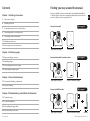
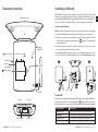
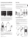
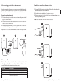
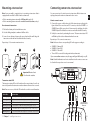
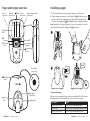
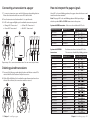
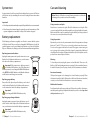
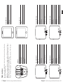
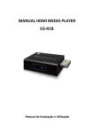
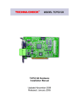
DESIGN FOR LIFE Contents Finding your way around the manual Chapter 1: Installing a transceiver Amicus is available in various models that require individual installation. To find the right section in the user manual, unpack all products and compare the contents to the descriptions below. 5 Transceiver overview 6 Installing a SIM card 7 Connecting a transceiver to a mobile phone 8 Interpreting alarms on a mobile phone 9 Connecting a wireless alarm unit Amicus basic model Go to page 11 11 Mounting a transceiver 12 Connecting sensors to a transceiver Pager with power supply Transceiver Chapter 2: Installing a pager 13 Pager and charger overview Amicus with module for wireless alarm Go to page 9 14 Installing a pager 15 Connecting transceivers to a pager 16 Interpreting the pager signals Chapter 3: Care and maintenance 17 System test and battery replacement Pager with power supply Transceiver with power supply 18 Care and cleaning Amicus with GSM module Go to page 6 Chapter 4: Troubleshooting and additional information 19Troubleshooting 21 Technical information 23 Personalizing the pager label 24 Important safety instructions 3 Contents Pager with power supply Transceiver with power supply Antenna Finding the right model 4 EN Transceiver overview Installing a SIM card With a GSM module you can receive alarms on your mobile phone. This is useful when you are outside the pager’s radio range. The transceiver needs to be equipped with a Micro SIM card (not prepaid). The PIN code needs to be switched EN off or set to 0000. To change the PIN code, see the operator’s user manual. Removable cover How to install a SIM card Note: First, make sure the transceiver is disconnected from the power supply. 1 Attach the GSM antenna and pull out the battery tab on the transceiver. 2 Open the cover and remove the batteries. Insert the SIM card into the holder in the battery compartment marked with a -symbol. The symbol indicates the direction. Wireless alarm LED 3 Put the batteries back and close the lid. Connect the power cord to the transceiver and plug it into the mains socket. The status LED will blink in green every 15 s to show that the transceiver is connected to GSM. If it doesn’t blink within 2 min go to Troubleshooting on p 19. Status LED Test button 1 Battery compartment 2 3 GSM LED SIM card port GSM antenna The GSM LED Sensor 1 Power supply 5 Chapter 1 Installing a transceiver Sensor 2 Sensor 3 The transceiver is equipped with a status LED that shows the current GSM status. It is located under the cover and marked with a -symbol. The LED shows e.g. if the transceiver is connected to the GSM network and when it is transmitting. If the GSM LED is It means that Blinking every 3 s • The transceiver is connected to a GSM network. Constantly lit • The transceiver is texting and calling an assistant. Blinking every 1 s • The transceiver is searching for a GSM network. Off • The transceiver has no GSM module/ it’s out of order. Chapter 1 Installing a transceiver 6 Connecting a transceiver to a mobile phone How it works To be able to send alarms over GSM, the transceiver must be connected to the assistant’s mobile phone. A transceiver can handle up to two assistants, named Assistant 1 and Assistant 2. 1 When a sensor is activated, the transceiver sends an alarm via text message to Assistant 1. As a safety precaution, it also makes a call (tone only). How to connect a transceiver 1 Send a text message with Assistant 1’s mobile number to the transceiver’s mobile subscription number according to the principle below. Remember to add spaces before and after the mobile number. Repeat for Assistant 2. Assistant 1 ALERT 'MOBILE NUMBER' A1 Assistant 2 ALERT 'MOBILE NUMBER' A2 For example: ALERT 07712 345678 A1 For example: ALERT 07787 654321 A2 2 To test the connection, press the transceiver test button. The transceiver will send a text message and call the assistants in the order stated on the following page. If no text or call is received, see Troubleshooting on p 19. Repeat steps 1-2 to connect a new transceiver. Remember to send the message to the new transceiver’s mobile subscription number. 1 2 ALERT 0704313335 A1 2 Assistant 1 has 20 s to respond to the call. To prevent confusion with voice mail, the call has to be concluded within 10 s. 3 If Assistant 1 fails to answer or hang up in time, the text message and call are redirected to Assistant 2. 1 2 3 A1 A2 How to interpret the alarm 1 To make it easy to separate the transceivers in your system, you need to add a contact in the mobile phone’s address book for each transceiver. Hint: Name the transceivers according to the caretakers’ name or room no. 2 When a sensor is activated on a transceiver, you will receive a text message with the following: Transceiver name (or mobile number if the contact is not in your address book) Activated sensor no. 1-3 The example below shows that sensor 1 in Hank’s room has been activated. Q W E R T Y I O P Å A S D F H J K L Ö Ä Z X C V B N M Note: You can replace an assistant by texting the new mobile number to the transceiver according to the ALERT 'NEW MOBILE NUMBER' A1 principle. To clear all numbers, text DELETE to the transceiver. Once deleted, the numbers cannot be restored. 7 Chapter 1 Installing a transceiver Chapter 1 Installing a transceiver 8 EN Connecting a wireless alarm unit Deleting wireless alarm units A wireless alarm unit is often worn on the wrist as a personal alarm, but can also come in the form of a wireless door- or motion sensor. In order to work with the system, the wireless alarm unit needs to be connected to the transceiver. 1 Press and hold the transceiver test button. Release the button when the transceiver status LED starts to blink in blue. Connecting a wireless alarm unit 3 The transceiver status LED shows that all connected alarm units have been deleted by blinking in green x 2. 1 Pull out the battery tab to start the transceiver. Connect the power cord and plug it into a mains socket. 2 Press and hold the transceiver test button. Release it when the transceiver status LED starts to blink in blue. 2 Press the transceiver test button x 3 in quick succession. Note: Once deleted, the connections cannot be restored. 1 3 Activate the alarm unit within 10 seconds to pair the units. The transceiver status LED will blink in green x 3 when ready. Repeat steps 2-3 to connect a new alarm unit. You can connect up to 4 units. 2 1 3 2 x3 Wireless alarm LED There is a LED under the cover that shows the current alarm status. It is marked with a - symbol (see Overview on p 6). The LED shows if an alarm unit is connected and when the transceiver receives an alarm. If the LED is It means that Lit / blinks in yellow • The transceiver is receiving an alarm / heartbeat. Lit in orange • The transceiver is ready to be connected to the alarm unit. Off • The transceiver has no wireless alarm module. • The module is out of order. 9 Chapter 1 Installing a transceiver 3 x2 Chapter 1 Installing a transceiver 10 EN Mounting a transceiver Connecting sensors to a transceiver Note: Some assembly is required prior to mounting a transceiver that is equipped with a module for GSM or wireless alarm unit. You can connect up to 3 wired sensors to a transceiver, like for instance an epilepsy alarm, an incontinence alarm and a door sensor. Before mounting a transceiver with a GSM module, read p 6-8. Before mounting a transceiver with a module for wireless alarm, read p 9. How to connect a sensor How to mount a transceiver 1 Pull out the battery tab to start the transceiver. 2 Use the drilling template to mark and drill two holes. 3 Leave a 2 mm distance between the screw head and the wall. Hang the transceiver on the wall and check that it is fitted securely. Repeat steps 1-3 to mount a new transceiver. 2 1 EN 1 Connect the sensor on the bottom side of the transceiver according to the figure below. If the sensor has an RJ11 connector, select the SENSOR 1 or SENSOR 2 input. If the sensor has a 3.5 mm mono tele jack plug, select the SENSOR 3 input. Check that the connectors and cables are fitted securely. 2 Verify the connection by activating the sensor. The transceiver status LED will blink in yellow to show that an alarm has been sent. Repeat steps 1-2 to connect a new sensor. Note: Each sensor has a corresponding LED on the pager according to: 3 Ф5.5mm SENSOR 1 - Orange LED SENSOR 2 - Green LED SENSOR 3 - Yellow LED The red LED is reserved for testing and wireless alarm units If you use more than one tranceiver, the pager will signal differently, see p 16. Note: Detailed information on how to install and use the various sensors can be found in the respective sensor’s user manual. Important! Mount at least 1.5 m from the caretaker. Transceiver status LED The transceiver status LED on the front shows the current status. It can for instance tell you when the transceiver sends an alarm or if an error has occurred. Hint: If an error occurs, check the LEDs under the cover for more information. If the LED is It means that Blinking in green • The system is working normally. Blinking in yellow • The transceiver is activated by a sensor and sending an alarm. Blinking in red • The transceiver’s battery level is low, see p 17. Blinking in purple • The batteries are fitted incorrectly/wrong type, see p 17. Blinking in white • The GSM module is searching network or out of order, see p 19. Blinking in blue • The wireless alarm unit is ready to be connected / error, see p 20. 11 Chapter 1 Installing a transceiver 1 2 3 The red LED is for testing and wireless alarm units 12 Pager and charger overview Installing a pager Sensor 1 Sensor 2 Wireless alarm and test On/Off Sensor 3 Transceiver 1 Transceiver 2 Transceiver 3 Transceiver 4 1 Pull out the battery tab on the pager and charger to start the units. Sound On/Off Replaceable label 2 Plug the charger into a mains socket. The power LED will light up to show EN that it is connected. Place the pager in the charger and check that it clicks into place. The charging LED will blink/light up to show that it’s charging. Note: Remember to charge the pager for 6 hours before using it for the first time. When fully charged, the charging LED will turn off. 1 No coverage Sound Off Transceiver error Low battery warning Acknowledge button Bed shaker (accessory) ”click” 2 Bed shaker outlet Power LED 13 Chapter 2 Installing a pager Bed shaker test button Charging LED How to use the pager When a sensor is activated, the pager will sound and vibrate. The LED color and blinking pattern shows which transceiver/sensor has been activated. If you want to Do this Switch off the pager alarm • Press the pager Acknowledge button. Mute the alarm • Push the pager Sound On/Off switch up/down. Switch the pager On/Off • Push the pager On/Off switch right/left. Chapter 2 Installing a pager 14 Connecting a transceiver to a pager How to interpret the pager signals 1 To connect a transceiver, press and hold the pager acknowledge button. Release the button when the two center LEDs start to blink. Using LED colors and blinking patterns, the pager shows which sensor and transceiver has been activated. 2 Press the transceiver test button within 10 s to pair the units. Note: The pager LED colors and blinking patterns differ depending on whether you have ONE or SEVERAL transceivers in the system. 3 A LED on the pager will light up to show that the transceiver is paired: Orange LED - Transceiver 1 Green LED - Transceiver 2 1 System with ONE transceiver - Each sensor has a dedicated LED color Yellow LED - Transceiver 3 Red LED - Transceiver 4 2 3 1 2 3 4 Activated transceiver Activated sensor Color and blinking pattern Transceiver 1 Sensor 1 Orange Transceiver 1 Sensor 2 Green Transceiver 1 Sensor 3 Yellow Transceiver 1 Wireless alarm unit Red Transceiver 1 Test button Red System with SEVERAL transceivers - Each transceiver has a dedicated LED color - The sensors are identified by blinking patterns Activated transceiver Activated sensor Color and blinking pattern Transceiver 1 Sensor 1 Orange Repeat steps 1-3 to connect a new transceiver. You can connect up to 4 units. Transceiver 1 Sensor 2 Orange Transceiver 1 Sensor 3 Orange Deleting paired transceivers Transceiver 1 Wireless alarm unit Orange 1 Press and hold the pager acknowledge button until the two center LEDs start to blink. Press the button x 3 in quick succession. Transceiver 1 Test button Orange Transceiver 2 Sensor 1 Green Transceiver 2 Sensor 2 Green Transceiver 2 Sensor 3 Green Transceiver 2 Wireless alarm unit Green Transceiver 2 Test button Green Transceiver 3 Sensor 1 Yellow Transceiver 3 Sensor 2 Yellow Transceiver 3 Sensor 3 Yellow Transceiver 3 Wireless alarm unit Yellow Transceiver 3 Test button Yellow Transceiver 4 Sensor 1 Red Transceiver 4 Sensor 2 Red Transceiver 4 Sensor 3 Red Transceiver 4 Wireless alarm unit Red Transceiver 4 Test button Red 2 All the LEDs will blink x 2 to show that the paired transceivers have been deleted. Once deleted, the connection cannot be restored. 1 15 Chapter 2 Installing a pager 2 Chapter 2 Installing a pager 16 EN System test It is important to check the system’s functionality at least once a week. Perform a full system test by activating all sensors and testing all transceiver alarm functions. Important! More frequent test intervals may be required if specified in the sensor user manual. More frequent test intervals may be required in special circumstances, if the system configuration is modified or if any of the units are dropped. Battery replacement Check battery performance regularly on all units to ensure that the system is fully functional. Please note that rechargeable NiMH batteries should be replaced approx. every 2 years. Always keep batteries out of reach of children. Dispose of batteries according to your local environmental laws and guidelines. Replacing transceiver batteries Unplug the mains power and open the transceiver cover. Replace the old batteries with new ones; see the instructions above the battery compartment. Important! If the transceiver is battery powered, use alkaline AAA batteries only. If the transceiver is mains powered, use rechargeable NiMH AAA batteries only. NEVER mix NiHM batteries with alkaline batteries as the batteries and charger can overheat. Replacing pager battery Remove the belt clip and open the battery cover located on the backside. Replace the old battery with a new one; see the instructions inside the battery compartment. Important! Use rechargeable NiMH AAA batteries only. Care and cleaning Notice: Failure to follow these care and cleaning instructions could result in damage to the products and void the warranty. Using connectors and jacks Never force a connector into a jack. Check for obstructions on the jack. If the connector and jack don’t join with reasonable ease, they probably don’t match. Make sure that the connector matches the jack and that you have positioned the connector correctly in relation to the jack. Using the products Operate the product in a dry environment where the temperature is always between 15° and 35° C. Do not use or store the products near a heat source. Do not use the pager in the bath or shower. If the pager or transceiver gets wet or is exposed to moisture, it should no longer be regarded as reliable and should therefore be replaced. Remove the batteries if you don’t plan to use the product for an extended period of time. Cleaning To clean the product, unplug the power cord and all cables. Then use a soft, lint-free cloth. Avoid getting moisture in openings. Don’t use window cleaners, household cleaners, aerosol sprays, solvents, alcohol, ammonia, or abrasives. Service and warranty If the product appears to be damaged or doesn’t function properly, follow the instructions in this leaflet. If the product still doesn’t function as intended, contact your local dealer for information on service and warranty. Additional information For information about the proper disposal of the product, and for other important safety and regulatory compliance information, see the section Important safety instructions on p 24. Replacing pager charger batteries Unplug the mains power and open the battery cover located on the bottom. Replace the old batteries with new ones; see the instructions inside the battery compartment. Important! Use rechargeable NiMH AAA batteries only. 17 Chapter 3 Care and maintenance Chapter 3 Care and maintenance 18 EN Troubleshooting Most problems with the product can be solved quickly by following the advice below. Transceiver If Try this The transceiver status LED blinks in red • The transceiver battery level is low. Replace the batteries if the transceiver is battery powered. Charge the batteries if it is mains powered. Important! If the transceiver is battery powered, use alkaline AAA batteries only. If the transceiver is mains powered, use rechargeable NiMH AAA batteries only. NEVER mix NiMH batteries with alkaline as the unit can overheat. The transceiver status LED blinks in purple • The transceiver batteries are fitted incorrectly or of the wrong type. See above for correct battery configuration and installation. The transceiver status LED blinks in white • The GSM module is indicating an error. Open the cover and check the GSM LED above the -symbol (see Transceiver overview on p 5). • If the LED is blinking every second, no GSM network has been detected. Check that the SIM card is fitted correctly and that you have GSM coverage in your area, see Installing a SIM card on p 6. When the transceiver is connected to a GSM network the GSM LED will blink every 3 s. • If the problem persists, contact your GSM provider. • If the LED is off, the unit has no GSM module or the module is out of order. Contact your dealer for service. The transceiver status LED blinks in blue • The transceiver is ready to be connected to a wireless alarm unit. • The alarm unit is faulty, see separate user manual. If the problem persists, contact your dealer for service. 19 Chapter 4 Troubleshooting and additional information Pager If Try this The pager’s -symbol is lit and the pager is vibrating and beeping • The pager has lost radio contact with a transceiver. If you have >1 transceiver, the LED position on the pager will show which transceiver is out of range. Move within radio range of the transceiver. The pager’s -symbol is lit and the pager is vibrating and beeping • A transceiver is indicating an error. If you have >1 transceiver, the LED position on the pager will show which transceiver is faulty. See Troubleshooting on p 19. The pager’s -symbol is white and the pager is vibrating and beeping • The pager has less than 2 h of battery life left. Charge the battery by placing the pager in the charger. A full charge takes up to 6 h. The pager’s -symbol is red and the pager is vibrating and beeping • The pager battery is of the wrong type, fitted incorrectly or flat. Check battery placement and performance, see Battery replacement on p 17. The pager is not emitting • The pager sound is switched off. Slide any sound and the -symthe sound switch upwards to turn on the bol is lit sound, see Pager overview on p 13. Pager charger If Try this The pager is not charging • Check that the pager is correctly placed in the charger. The LED by the -symbol will blink/light up to show that it’s charging. • Check that the charger is connected to mains power. The LED by the -symbol is lit to show that it is connected. If the LED blinks, it is using the backup battery. The backup batteries in the • Check that the backup batteries are fitted charger is not working and correctly and charged. Charge or replace the -symbol is off them, see Battery replacement on p 17. Chapter 4 Troubleshooting and additional information 20 EN Technical information Amicus transceiver Amicus pager Dimensions & weight h 140 mm x w 105 mm x d 30 mm, 210 g incl. batteries Dimensions & weight h 91 mm x b 55 mm x d 23 mm, 60 g incl. battery Battery power 1 x 1.2 V AAA rechargeable NiMH battery. Use the supplied rechargeable battery model HFR-AAA900 900 mAh by Shenzen Highpower Technology Co. Ltd. Operating time 24 h Charging time Up to 6 h Power consumption 20 mA Activation Via radio Radio frequency 869.2375 MHz Range Up to 600 m line of sight. The range is reduced by walls and large objects that obstruct radio signals. The range can also be affected by other radio transmitters such as TVs, PCs, mobile phones or tablets. Environment For indoor use only. Temperature range: 15° - 35° C Relative humidity: 5% - 95%, non-condensing Regulatory Fulfils WEEE, CE, RoHS and R&TTE Mains power Input: 100 – 240 V ~ 50/60 Hz 0.3 A Output: 7.5 V 1000 mA Use the supplied adaptor model SSA-10W-12 EU 075100 by SIL Batteries With mains electricity: 4 x 1.2 V AAA rechargeable NiMH batteries. Use the supplied rechargeable batteries model HFR-AAA900 900 mAh by Shenzen Highpower Technology Co. Ltd., or model 5703 1000 mAh by Varta. Without mains electricity: 4 x 1.5V AAA alkaline batteries. Operating time 365 days without GSM module or wireless alarm unit 4 h reserve with GSM module or wireless alarm unit Power consumption 0.3 mA in basic configuration Connections 1 x 7.5V power cord 2 x RJ-11 inputs 1 x 3.5 mm tele jack 1 x SMA jack for GSM antenna Activation Via test button Via sensors connected to the 3 sensor inputs Via wireless alarm unit (module BE9230 required) Radio frequency 869.2375 MHz Range Up to 600 m line of sight. The range is reduced by walls and large objects that obstruct radio signals. The range can also be affected by other radio transmitters such as TVs, PCs, mobile phones or tablets. Environment For indoor use only Temperature range: 15° - 35° C Relative humidity: 5% - 95%, non-condensing Shall be installed at least 1.5 m from the caretaker Regulatory Fulfils WEEE, CE, RoHS and R&TTE Accessories BE9220 Module for GSM BE9230 Module for wireless alarm units Amicus pager charger Dimensions & weight h 110 mm x w 93 mm x d 110 mm, 195 g incl. batteries Mains power Input: 100-240V~50/60Hz 0.5A, Output: 7.5V 1600mA Use the supplied adaptor model SFP0751600P made by Helms-Man. Battery power 4 x 1.2 V AAA rechargeable NiMH batteries. Use the supplied rechargeable batteries model 80AAAHC 800 mAh by GP. Power consumption 200 mA Connections 7.5V power cord 3.5 mm tele jack for bed shaker Activation Via the test button that activates a bed shaker Environment For indoor use only. Temperature range: 15° - 35° C Relative humidity: 5% - 95%, non-condensing Regulatory Fulfils WEEE, CE, RoHS and R&TTE Accessories BE1270 Bed shaker CAUTION! Explosion hazard if battery is replaced by an incorrect type. Dispose of used batteries according to the recycling instructions. 21 Chapter 4 Troubleshooting and additional information Chapter 4 Troubleshooting and additional information 22 EN Personalizing the pager label Important safety instructions A personalized label makes it easier to identify the different pager alarms. Depending on configuration, you can write the name of the caretakers or the installed sensors. An extra label is included in the package. This section contains important information about safety, handling, disposal, recycling and warranty. Replacing a label 1 Remove the transparent plastic cover protecting the LED panel. Be careful not to damage the plastic. Notice: Read all safety information and operating instructions below before using the Amicus products. Keep the user manual for future use. 2 Replace the label. Warning! 3 Snap the plastic cover back into place. Failure to follow these safety instructions could result in fire, electric shock, or other injury or damage to the product or other property. Note: You can download and editable PDF version on our website. Do not use or store this product near any heat sources such as naked flames, radiators, ovens or other devices that produce heat. 1 2 Protect the cables from any potential source of damage. Use only the power supply and accessories specified in this manual. Disconnect the power supply from the mains during thunderstorms or if the product is not in use for a long period of time. If the product is dropped, always test it before using it. Please note that the deliberate or accidental switching off of the volume or power switch on the Pager can result in a missed alarm. Be aware that alarms can be missed if batteries run out, connectors become disconnected, or mobile systems are out of operation. Only refer damaged or faulty products to qualified service personnel. 3 Do not dismantle the product; there is a risk of electric shock. Tampering with or dismantling the product will void warranty. The product is intended to be used as a care alerting system but should not be used as the only security in life-threatening situations. This product does not replace the need for personal supervision of caretakers. The product has no power switch. In order to disconnect the product, the charger and power supply must be disconnected from the mains power. Make sure that these are easily accessible. The product is designed for indoors use only. Do not expose the product to moisture. Protect the product from shocks during storage and transport. 23 Chapter 4 Troubleshooting and additional information Chapter 4 Troubleshooting and additional information 24 EN Model, type and classification The information is available at the back of the transceiver and pager charger. Product disposal and recycling information EN The symbol to the left means that according to local laws and regulations your product should be disposed of separately from household waste. When this product reaches its end of life, take it to a collection point designated by local authorities. The recycling of your product will help conserve natural resources and ensure that it is recycled in a manner that protects human health and the environment. Battery disposal information This symbol indicates that the product contains batteries that according to local laws and regulations must be disposed of separately from household waste. Take used batteries to a collection point designated by local authorities. The European Union - declaration of conformity 0359 Hereby, Bellman & Symfon Europe AB, declares that this product is in compliance with the essential requirements and other relevant provisions of R&TTE 1999/5/EC, LVD 2006/95/EC, MDD 93/42/EEC and EMC 2004/108/EC directives. The declaration of conformity may be consulted at Bellman & Symfon Europe AB, Södra Långebergsgatan 30, 421 32 Västra Frölunda, Sweden. © and TM 2015 Bellman & Symfon AB. All rights reserved. Amicus, Bellman and Bellman & Symfon are registrered trademarks owned by Bellman & Symfon AB. 25 Chapter 4 Troubleshooting and additional information Chapter 4 Troubleshooting and additional information 26 27 Chapter 4 Troubleshooting and additional information Name: Mobile: Green LED: Yellow LED: Transceiver 2 Mobile: Sensor 1: Sensor 2: Sensor 3: Wireless alarm: Transceiver 4 Mobile: Sensor 1: Sensor 2: Sensor 3: Wireless alarm: Transceiver 1 Mobile: Sensor 1: Sensor 2: Sensor 3: Wireless alarm: Transceiver 3 Mobile: Sensor 1: Sensor 2: Sensor 3: Wireless alarm: Red LED: Assistant 2 Mobile: Name: Assistant 1 Orange LED: Pagers If you need more pages, go to our website for a PDF version. Hint: You can for instance make notes of the sensors, transceivers and pagers in the system and write down the assistants’ names and contact information. You can use the illustration below to document your Amicus system configuration. My notes EN Chapter 4 Troubleshooting and additional information 28 BE2320_001MAN001 DESIGN FOR LIFE ™