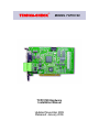
1
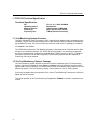
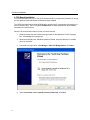
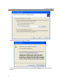
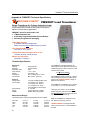
TECHNA-CHECK®
MODEL TCPCI120
TCPCI120 Hardware
Installation Manual
Updated November 2009
Released: January 2006
Contents
© Copyright 2003-2006, Techna-Tool Inc., Hartland, Wisconsin, USA.
The information in this document is subject to change without notice.
TECHNA-CHECK® is a registered trademark of Techna-Tool Inc.
2
Table Of Contents
1. TCPCI120 Technical Specification .......................................................................... 4
1.1 Tool-Monitoring-System Overview..................................................................... 4
1.2 The Tool Monitor ‘System’ Concept................................................................... 4
2. PCI-Board Installation .............................................................................................. 5
3. TTBUS Networking .................................................................................................. 9
3.1 TTBus Wiring ..................................................................................................... 9
4. Profibus Networking................................................................................................. 10
4.1 Profibus Cycle-Time Considerations ................................................................. 10
4.2 The output telegram from the Profibus Master to the TCPCI120 ...................... 10
4.3 The input telegram from TCPCI120 to the Profibus Master ............................. 11
4.4 The Profibus GSD File TPCI0A0B.GSD ........................................................... 12
Appendix A-PWM350T Technical Specification....................................................... 14
Appendix B-VM100T Technical Specification .......................................................... 16
Appendix C-IO100T Technical Specification............................................................ 18
3
TPCI120 Technical Specification
1. TCPCI120 Technical Specification
Technical Specification:
PCI
Operating System
Minimum System
Profibus Dp
Proprietory Bus
PCI rev. 2.2 - 32bit 33/66MHz.
Windows XP
1Ghz Pentium 512MB RAM
DPV1 Interface (9pin Dsub).
TTBUS (Phoenix Connector)
1.1 Tool Monitoring System Overview
The main component of the PCI system is a PCI card which will always need to be inserted into a
computer. The PCI card could be inserted into a CNC controller which is Windows XP based and
has available PCI slots. The card could also be used in a stand alone PC (desktop) or Industrial
PC installed in the machine.
The TCPCI120 interfaces the Tool Monitoring System to the Machine NC-Controller and to different types of Tool Monitor sensors. The TCPCI120 is thus basically a communication controller;
the actual Tool-Monitoring is realized by the application TTMON, running on the PC. TTMON implements a maximum of a 20 channel (spindle) Tool Monitoring System with the capability of
monitoring 128 cuts per channel.
1.2 The Tool Monitoring ‘System’ Concept
The Tool Monitoring System provides a common interface to different types of Tool Monitoring
Sensors. Monitoring is based on either Power or Vibration. The NC-controller provides control
signals (Start, Learn and Reset), Cut Number and in some cases Measurement Values to the Tool
Monitoring System. The Tool Monitoring System returns Alarms in case of Tooling Faults.
In this way the details about the operation of the various Tool Monitoring Functions are effectively
hidden by the NC-controller.
The actual operation of the Tool-Monitoring PC-application TTMON is covered in a separate user
manual.
.
4
PCI-Board Installation
2. PCI-Board Installation
The TCPCI120 Board is a Plug ‘n’ Play (PnP) board and will be recognized by Windows XP during
the first operating system boot after the board has been installed.
The TCPCI120 Board uses a Windows WDM driver supplied by PLX Corporation (the designer of
the PCI-interface chip). The PLX-supplied PciSdk.inf file provides Windows with the necessary
information to install the driver.
When the PC boots and the board is found you should see this:
1. Windows detects the new hardware and generates a “New Hardware Found” message
box. Acknowledge the message box.
2. Windows the displays the “Add New Hardware” Wizard, which will search for a suitable
driver for the board.
3. The board is recognized as a PCI Bridge or Other PCI Bridge Device. Click Next.
4.
5
Select Install from a list or specific location (Advanced). Click Next
PCI-Board Installation
5. Browse for the Driver Location. Click Next.
6. The driver was submitted to Microsoft for so called Driver Signing. Please Select “Continue
Anyway”.
6
PCI-Board Installation
7. Driver installed successfully.
The driver can now be found in device manager as Other devices - PLC Custom (OEM) PCI
9056 Board.
7
PCI-Board Installation
Driver Information.
8
The TTBUS Interface
3. TTBUS Networking
The TTBUS is a Proprietory Communication Bus designed to interface multiple Measurement
Transducers and/or Digital I/O units to the Tool-Monitoring-System. The TTBUS is based upon
traditional RS485 hardware.
Today 3 different TTBUS devices have been developed.
PWM350T
VM100T
I/O100T
3-Phase Power Transducer
Vibration Sensor Interface Unit
Digital I/O Unit.
In the future other type of sensors may be added.
Detailed specifications of the TTBUS units are found in the appendices of this manual. Each
TTBUS unit is assigned a unique address on the network. The address is programmed by 2 BCD
switches located on the front of the transducers. The Tool Monitoring System automatically locates transducers on the TTBUS. A Channel Mapping menu in TTMON is used to map the different transducers to the different channels.
3.1 TTBUS Wiring
TCPCI120
TT-B
#50
#49
#48
I/O100T
I/O100T
TC6400
I/O100T
TT-A
Term.
TT-B
TT-A
TT-B
Profibus LED
Profibus Dsub
TT-A
TTBUS
1
2
3
4
5
6
Term.
TT-A
TT-B
Earth
TT-B
TT-A
TT-B
TT-A
TT-B
TT-A
VM100T
PWM350T
PWM350T
#2
#1
#0
Important note:
Please use good-quality low-resistance twisted and shielded cable earth-connected at one or both
ends for the TTBUS network.
Last unit in the TTBUS network chain must be terminated.
Termination is possible in all units by adding external wire.
Make the stubs as short as possible.
9
The Profibus Interface
4. Profibus Networking
4.1 Profibus Cycle-Time Considerations
The Profibus cycle time should be a maximum of 10 -15 ms (milliseconds) equal to 67 – 100
profibus telegram transfers per second. To achieve this a Profibus transmission speed (baud rate)
of 1Mb and higher is probably required. If this requirement is not met the synchronization from
cycle to cycle is affected and also measurement accuracy may be lost (if the measurement value
is supplied from the Profibus network).
4.2 The output telegram from the Profibus Master to the TCPCI120
The output telegram length is always 80 bytes - 4 bytes for each channel. Data is always sent for
20 channels no matter how many channels are actually used. Data sent for channels not present
should be zero. The purpose of the output telegram is to supply control signals, cut number and
possibly measurement value to the TCPCI120 Tool Monitoring System.
Telegram Format:
BitFlags#1, Measurement#1, CutNumber#1,BitFlags#2, Measurement#2,
CutNumber#2, ……………………
BitFlags#20, Measurement#20, CutNumber#20
Telegram Data-Byte Numbering:
Byte No
0
BitFlags#1
1, 2
Measurement#1
3
CutNumber#1
4
BitFlags#2
5, 6
Measurement#2
7
CutNumber#2
…..
76
BitFlags#20
77, 78
Measurement#20
79
CutNumber#20
Channel #1 – 8 bits
Channel #1 – 16 bits
Channel #1 – 8 bits
Channel #2 – 8 bits
Channel #2 – 16 bits
Channel #2 – 8 bits
Channel #20 – 8 bits
Channel #20 – 16 bits
Channel #20 – 8 bits
BitFlags# - b7b6b5bb3b2b1b0
#define PROFIBUS_MODE_MASK
(PROFIBUS_MODE1 | PROFIBUS_MODE2 | PROFIBUS_MODE3) // b6b5b4
// PROFIBUS - bit_signals –
Externally Generated Signals - Inputs
#define START_SIGNAL_ACTIVATED
0x01
#define LEARN_SIGNAL_ACTIVATED
0x02
#define RESET_ALARM_SIGNAL_ACTIVATED 0x04
#define PROFIBUS_SPARE
0x08
#define PROFIBUS_MODE1
0x10
#define PROFIBUS_MODE2
0x20
#define PROFIBUS_MODE3
0x40
#define PROFIBUS_UNIT_PRESENT
0x80
// b0 = Start Signal
// b1 = Learn Signal
// b2 = Reset Signal
// b3 = not used
// b4 = Profibus mode
// b3 = Profibus mode
// b2 = Profibus mode
// b1 = Channel Present
Measurement# – 2 Byte MSB, LSB
16 bit measurement value 0 – 1000 decimal = 0.0 – 100.0%
CutNumber# – 1 Byte
10
The Profibus Interface
4.3 The input telegram from TCPCI120 to the Profibus Master
The input telegram (to the Profibus Master) is always 20 bytes long – 1 byte for each channel.
Channel #1 is first and Channel #20 is the last byte. The purpose of the inputs is to report Alarms
and other status information to the master (NC controller).
Telegram Format:
InputFlags#1, InputsFlags#2 …………… InputFlags#20
InputFlags - b7b6b5bb3b2b1b0
#define ACTIVE_READY
0x01
#define
#define
#define
#define
#define
#define
#define
0x02
0x04
0x08
0x10
0x20
0x40
0x80
SPARE1
TOUCHED
IDLE_ALARM
BLUNTCOUNT_ALARM
MISSING_ALARM
BLUNT_ALARM
BREAK_ALARM
// b0 = Po Measured or Touched
(BK MICRO)
// b1 = bit not used
// b2 = Touched
// b3 = IDLE_ALARM
// b4 = BLUNTCOUNT_ALARM
// b5 = MISSING_ALARM
// b6 = BLUNT_ALARM
// b7 = BREAK ALARM
ACTIVE_READY
This bit is set when the Tool Monitoring becomes active.
Example1: Start Signal has been activated and Idle Power calculated.
Example2: Target tool has been checked for presence – future BK Mikro application.
In some cases cycle time can be saved by waiting for this bit to get activated before the tool feeds
towards the target. The alternative (or maybe traditional way) is to introduce a fixed delay large
enough until Idle Power has been calculated.
SPARE1
Not used.
TOUCHED
Is used with the Touch-Limit function and set when the tool touches the part – signal reaches the
touch-limit.
IDLE_ALARM
Signals the presence of an IDLE_ALARM.
BLUNTCOUNT_ALARM
Signals the presence of a BLUNTCOUNT_ALARM.
MISSING_ALARM
Signals the precense of a MISSING_ALARM.
BLUNT_ALARM
Signals the precense of a BLUNT_ALARM.
BREAK_ALARM
Signals the precense of a BREAK_ALARM.
11
The Profibus GSD File TPCI0A0B.GSD
4.3 The Profibus GSD File TPCI0A0B.GSD
; ===========================================================
; Techna Tool Inc.
;
; File : TPCI0A0B.GSD
; Revision : 1.0
; Last Modification : 05/09/2005
; ===========================================================
;
#Profibus_DP
; General device information
GSD_Revision
= 1
Vendor_Name
= "Techna Tool Inc."
Model_Name
= "TPCI120"
Revision
= "V1.0"
Ident_Number
= 0x0A0B
Protocol_Ident
= 0
; 0 = PROFIBUS-DP only
Station_Type
= 0
; 0 = DP-Slave
FMS_supp
= 0
; FMS is not supported
Hardware_Release
= "A1"
Software_Release
= "V1.0"
; Supported baudrates
9.6_supp
19.2_supp
45.45_supp
93.75_supp
187.5_supp
500_supp
1.5M_supp
3M_supp
6M_supp
12M_supp
=
=
=
=
=
=
=
=
=
=
1
1
1
1
1
1
1
1
1
1
; MaxTsdr default values for supported baudrates
MaxTsdr_9.6
= 60
MaxTsdr_19.2
= 60
MaxTsdr_45.45
= 60
MaxTsdr_93.75
= 60
MaxTsdr_187.5
= 60
MaxTsdr_500
= 100
MaxTsdr_1.5M
= 150
MaxTsdr_3M
= 250
MaxTsdr_6M
= 450
MaxTsdr_12M
= 800
; General supported features
Redundancy
= 0
; Redundancy not supported
Repeater_Ctrl_Sig
= 2
; RTS Signal with TTL level
24V Pins
= 0
;
Implementation_Type
= "ASIC_solution, VPC3+"
12
The Profibus GSD File TPCI0A0B.GSD
; DP Slave related information
Freeze_Mode_supp
= 0
Sync_Mode_supp
= 0
Auto_Baud_supp
= 1
Max_Diag_Data_Len
= 6
Set_Slave_Add_supp
= 0
User_Prm_Data_Len
= 05
Min_Slave_Intervall
= 5
Slave_Family
= 1@TT@TPCI
; Modules information
Modular_Station
Max_Module
Max_Input_Len
Max_Output_Len
Max_Data_Len
=
=
=
=
=
; Freeze-Mode not supported
; Sync.-Mode not supported
; Automatic baud control supported
; Set Slave address not supported
;
; 500us
0
1
20
80
100
Module = "80 Byte out/ 20 Byte In" 0x2f,0x2f,0x2f,0x2f,0x2f,0x1f,0x13
EndModule
13
PWM350T Technical Specification
Appendix A. PWM350T Technical Specification
TT TECHNA-CHECK
®
PWM350T Load Transducer
Power Transducer for 3
3--phase Inductive Loads
A fast measurement transducer specifically developed for
Machine Tool Monitoring applications.
PWM350T measures motor power, kW.
♦ TTBUS Networked Unit
.
♦ 4 Remotely Programmable Measurement Ranges
♦ Remotely Programmable Averaging
Power Measurement
4 quadrant analogue multiplication.
Measures power after variable frequency inverter.
Ultra Compact DIN rail mount
Less than 2” of rail space.
Current wires feeds through 3 holes in unit
3 internal 50 Amp. current sensors.
Monitor any size motor
(external CT >50Amp.)
Technical Specification
Mechanical
Housing:
Mounting:
Protection Class:
Temp. Range:
Weight:
Dimensions:
Connections:
Polycarbonate.
35 mm DIN-rail.
IP40.
-15 to + 50 C.
App. 500g (1 lb).
D 118 x B 45 x H 137,5 mm.
Max 2,5 mm2 (AVG 24).
Electrical
Voltage Input:
Current Input:
3 x 0-500 V PWM (0-600V max).
3 x 50 Amp. 5Hz - 5kHz or
3 x 25 Amp. 5Hz - 5kHz or
3 x 12,5 Amp. 5Hz - 5kHz
see side label for actual range
0 - 43.3 kW.
18-36 V DC max. 2.5 Watt.
RS485 electrically isolated.
Power Range:
Supply:
TTBUS:
Measurement Ranges
The Measurement range is programmable from the TTBUS.
Unit Type
100%
50%
20%
5%
14
3 x 50 A .
43.3 kW
21.7 kW
8.66 kW
2.17 kW
3 x 25 A.
21,7 kW
10,8 kW
4,33 kW
1,08 kW
3 x 12,5 A
10,8 kW
5,42 kW
2,17 kW
0,54 kW
The PWM350T is designed primarily for
measuring the power delivered to motors by
variable frequency inverters. Power is measured from the formula:
P = √3 x U x I x Cosϕ
The PWM350T Power Transducer is specifically developed to function as a load transducer for the TECHNA CHECK® Range of
Machine Tool Monitors.
The PWM350T is available as a 3 x 50 Amp,
3 x 25 Amp or a 3 x 12,5 Amp transducer.
The three motor wires U, V and W must
pass through the holes in the transducer in
the same direction to the motor either from
Top-Bottom or from Bottom-Up.
Note: The PWM350T is designed for use
with inductive loads only (motors).
TECHNA-CHECK® is a registrered trade
mark of Techna-Tool Inc., Hartland Wisconsin USA.
PWM350T Wiring
(example 1)
Frequency Inverter
(1 phase fed)
L
N
U
V
W
(example 2)
Frequency Inverter
(3 phase fed)
L1
L2
L3
U
V
W
Measurement
Transducer
Term.
TT-A
TT-B
PWM
350T
1
2
3
4 5 6 7 8
+24V
Gnd
M
3~
Profibus Dsub
1
2
3
4
5
6
Term.
TT-A
TT-B
TCPCI120
Techna Tool Inc.
Profibus LED
TPCI120 ver. 2.0
TTBUS
Earth
Note!
Please use good-quality low-resistance twisted and shielded cable earth-connected at one or both
ends for the TTBUS network.
Last unit in the TTBUS network chain must be terminated.
Please connect a wire between terminal 6 and 8 on the PWM350T (the TTBUS slave) when termination
is required
15
VM100T Technical Specification
Appendix B. VM100T Technical Specifications
TT
TECHNA-CHECK
®
VM100T Vibration Interface
Vibration Sensor Interface
A measurement transducer, which provides Vibration
Monitoring for the TECHNA-CHECK® units.
.
VM100T measures vibration (acceleration).
♦ TTBUS Networked Unit
♦ 4 Remotely Programmable Measurement Ranges
♦ 4 Remotely Programmable RMS averaging periods
♦ Remotely Programmable filters
Technical Specification
Mechanical
Housing:
Mounting:
Protection Class:
Temp. Range:
Weight:
Dimensions:
Connections:
Electrical
Sensor Input:
Vibration Range:
Supply:
TTBUS:
Polycarbonate.
35 mm DIN-rail.
IP40.
-15 to + 50 C.
App. 300g (1 lb).
D 118 x B 45 x H 137,5 mm.
Max 2,5 mm2 (AVG 24).
Proprietory.
Sensor supplied with unit.
+- 0.5G, 0 - 1000 Hz
18-24 V DC max. 2.5 Watt.
RS485.
The VM100T interfaces a propriety acceleration sensor to the existing TECHNA-CHECK® range of
Machine Tool Monitors.
The purpose of the vibration monitoring is to catch the damage of a tool like a milling cutter, which
has damaged one of its inserts. When one insert is broken the next insert is forced to cut twice the
amount of material, which will generate machine vibrations to be picked up by the VM100T.
Another application is to protect high-speed spindles against operation with an unbalanced tool,
which may lead to rapid wearing and destruction of the spindle bearings.
TECHNA-CHECK® is a registered trade mark of Techna-Tool Inc., Hartland Wisconsin USA.
16
VM100T Wiring
Measurement
Transducer
Gnd
+24V
Vibration Sensor
Acc+
AccEarth
Term.
TT-A
TT-B
VM 100T
1 2 3 4 5 6
7 8
+24V
Gnd
Shielded cable earth
connected at one end
Profibus Dsub
1
2
3
4
5
6
Term.
TT-A
TT-B
Techna Tool Inc.
TCPCI120
Profibus LED
TPCI120 ver. 2.0
TTBUS
Earth
Note!
Please use good-quality low-resistance twisted and shielded cable earth-connected at one or both
ends for the TTBUS network.
Last unit in the TTBUS network chain must be terminated.
Please connect a wire between terminal 4 and 6 on the VM100T (the TTBUS slave) when termination is
required
17
IO100T Technical Specifications
Appendix C. IO100T Technical Specifications
TT
TECHNA-CHECK
®
IO100T Digital I/O Interface
Parallel Digital I/O Interface
An interface unit which interfaces traditional parallel I/O to the
TECHNA CHECK® TPCI120 unit.
IO100T features.
♦ TTBUS Networked Unit
♦ 3 Relay Alarm Outputs
♦ 7 Digital Inputs for Cut-Number
♦ Digital Input for START and RESET
Technical Specification
Mechanical
Housing:
Mounting:
Protection Class:
Temp. Range:
Weight:
Dimensions:
Connections:
Polycarbonate.
35 mm DIN-rail.
IP40.
-15 to + 50 C.
App. 300g (1 lb).
D 118 x B 45 x H 137,5 mm.
Max 2,5 mm2 (AVG 24).
Electrical
Digital Inputs:
Relay Outputs:
Sensor Input:
Supply:
10-30 VDC.
250 VAC max, 5 A max.
Proprietory. Sensor supplied with unit.
18-24 V DC max. 2.5 Watt.
The IO100T interfaces traditional NC-controllers, which are not
Profibus capable, to the TECHNA CHECK® TPCI120 ToolMonitor-System.
It is possible for multiple channels (spindles) to share a single
IO100T. Could be a round-table machine where all stations
changes operation (production change) simultaneously. In this
case the alarms outputs is the logical OR of alarms generated
by the channels. Thus if one channels makes an alarm the corresponding alarms relay is activated.
TECHNA CHECK® is a registered trade mark by Techna- Tool
Inc., Hartland Wisconsin USA.
Digital inputs S0 - S8
S0 .... S8
10-30 V
Sgnd
18
IO100T Connection to TPCI120
Sgnd
S8
S7
S6
S5
S4
S3
S2
S1 (RESET)
S0 (START)
+24V
Gnd
Gnd
+24V
S0
S1
S2
S3
S4
S5
S6
S7
S8
SGnd
1 2 3 4 5 6 7 8 9 10 11 12
Digital I/O
Interface
C1
NO1
NC1
C2
NO2
NC2
C3
NO3
NC3
Term.
TT-A
TT-B
IO 100T
13 14 15 16 17 18 19 20 21 22 23 24
Break
Blunt
Missing
Idle
Touch
Point
Profibus Dsub
1
2
3
4
5
6
Term.
TT-A
TT-B
TCPCI120
Techna Tool Inc.
Profibus LED
TPCI120 ver. 2.0
TTBUS
Earth
Note!
Please use good-quality twisted pair and shielded cable, earth-connected at one or both ends
for the TTBUS network.
Last unit in the TTBUS network chain must be terminated.
Please connect a wire between terminal 22 and 24 on the IO100T (the TTBUS slave), when
termination is required.
19