1
MOTLoad Firmware Package
User’s Manual
P/N: 6806800C24D
February 2015
©
Copyright 2015 Artesyn Embedded Technologies, Inc.
All rights reserved.
Trademarks
Artesyn Embedded Technologies, Artesyn and the Artesyn Embedded Technologies logo are trademarks and service marks of
Artesyn Embedded Technologies, Inc.© 2015 Artesyn Embedded Technologies, Inc. All other product or service names are the
property of their respective owners.
Intel® is a trademark or registered trademark of Intel Corporation or its subsidiaries in the United States and other countries.
Java™ and all other Java-based marks are trademarks or registered trademarks of Oracle America, Inc. in the U.S. and other countries.
Microsoft®, Windows® and Windows Me® are registered trademarks of Microsoft Corporation; and Windows XP™ is a trademark of
Microsoft Corporation.
PICMG®, CompactPCI®, AdvancedTCA™ and the PICMG, CompactPCI and AdvancedTCA logos are registered trademarks of the PCI
Industrial Computer Manufacturers Group.
UNIX® is a registered trademark of The Open Group in the United States and other countries.
Notice
While reasonable efforts have been made to assure the accuracy of this document, Artesyn assumes no liability resulting from any
omissions in this document, or from the use of the information obtained therein. Artesyn reserves the right to revise this document
and to make changes from time to time in the content hereof without obligation of Artesyn to notify any person of such revision or
changes.
Electronic versions of this material may be read online, downloaded for personal use, or referenced in another document as a URL to
an Artesyn website. The text itself may not be published commercially in print or electronic form, edited, translated, or otherwise
altered without the permission of Artesyn.
It is possible that this publication may contain reference to or information about Artesyn products (machines and programs),
programming, or services that are not available in your country. Such references or information must not be construed to mean that
Artesyn intends to announce such Artesyn products, programming, or services in your country.
Limited and Restricted Rights Legend
If the documentation contained herein is supplied, directly or indirectly, to the U.S. Government, the following notice shall apply
unless otherwise agreed to in writing by Artesyn.
Use, duplication, or disclosure by the Government is subject to restrictions as set forth in subparagraph (b)(3) of the Rights in
Technical Data clause at DFARS 252.227-7013 (Nov. 1995) and of the Rights in Noncommercial Computer Software and
Documentation clause at DFARS 252.227-7014 (Jun. 1995).
Contact Address
Artesyn Embedded Technologies
Marketing Communications
2900 S. Diablo Way, Suite 190
Tempe, Arizona 85282
Artesyn Embedded Technologies
Lilienthalstr. 17-19
85579 Neubiberg/Munich
Germany
Contents
About this Manual . . . . . . . . . . . . . . . . . . . . . . . . . . . . . . . . . . . . . . . . . . . . . . . . . . . . . . . . . . . . . . . . . . . . . . . 13
1
Introduction . . . . . . . . . . . . . . . . . . . . . . . . . . . . . . . . . . . . . . . . . . . . . . . . . . . . . . . . . . . . . . . . . . . . . . . . . 19
1.1
2
Using MOTLoad . . . . . . . . . . . . . . . . . . . . . . . . . . . . . . . . . . . . . . . . . . . . . . . . . . . . . . . . . . . . . . . . . . . . . . 23
2.1
2.2
2.3
2.4
3
Overview . . . . . . . . . . . . . . . . . . . . . . . . . . . . . . . . . . . . . . . . . . . . . . . . . . . . . . . . . . . . . . . . . . . . . . . . . . 19
1.1.1 MOTLoad Implementation and Memory Requirements . . . . . . . . . . . . . . . . . . . . . . . . . . . 19
1.1.2 MOTLoad Commands . . . . . . . . . . . . . . . . . . . . . . . . . . . . . . . . . . . . . . . . . . . . . . . . . . . . . . . . 19
1.1.3 MOTLoad Utility Applications . . . . . . . . . . . . . . . . . . . . . . . . . . . . . . . . . . . . . . . . . . . . . . . . . . 20
1.1.4 MOTLoad Tests . . . . . . . . . . . . . . . . . . . . . . . . . . . . . . . . . . . . . . . . . . . . . . . . . . . . . . . . . . . . . . 20
Overview . . . . . . . . . . . . . . . . . . . . . . . . . . . . . . . . . . . . . . . . . . . . . . . . . . . . . . . . . . . . . . . . . . . . . . . . . . 23
2.1.1 Command Line Interface . . . . . . . . . . . . . . . . . . . . . . . . . . . . . . . . . . . . . . . . . . . . . . . . . . . . . . 23
2.1.2 Command Line Help. . . . . . . . . . . . . . . . . . . . . . . . . . . . . . . . . . . . . . . . . . . . . . . . . . . . . . . . . . 24
2.1.3 Command Line Rules . . . . . . . . . . . . . . . . . . . . . . . . . . . . . . . . . . . . . . . . . . . . . . . . . . . . . . . . . 25
2.1.4 Command History Buffer. . . . . . . . . . . . . . . . . . . . . . . . . . . . . . . . . . . . . . . . . . . . . . . . . . . . . . 26
2.1.5 pseudo-Vi Mode . . . . . . . . . . . . . . . . . . . . . . . . . . . . . . . . . . . . . . . . . . . . . . . . . . . . . . . . . . . . . 26
2.1.6 Command Line Execution Modes. . . . . . . . . . . . . . . . . . . . . . . . . . . . . . . . . . . . . . . . . . . . . . . 27
2.1.7 Copying/Transferring MOTLoad Images. . . . . . . . . . . . . . . . . . . . . . . . . . . . . . . . . . . . . . . . . 28
MOTLoad Command Description Page Format . . . . . . . . . . . . . . . . . . . . . . . . . . . . . . . . . . . . . . . . . 29
User Download Buffer . . . . . . . . . . . . . . . . . . . . . . . . . . . . . . . . . . . . . . . . . . . . . . . . . . . . . . . . . . . . . . . 31
Standard Error Codes and Devices . . . . . . . . . . . . . . . . . . . . . . . . . . . . . . . . . . . . . . . . . . . . . . . . . . . . 31
2.4.1 Error Message Formats . . . . . . . . . . . . . . . . . . . . . . . . . . . . . . . . . . . . . . . . . . . . . . . . . . . . . . . 32
2.4.2 IOCTL Codes (Block) . . . . . . . . . . . . . . . . . . . . . . . . . . . . . . . . . . . . . . . . . . . . . . . . . . . . . . . . . . 32
2.4.3 Standard Error Codes (errno) . . . . . . . . . . . . . . . . . . . . . . . . . . . . . . . . . . . . . . . . . . . . . . . . . . 33
MOTLoad Commands . . . . . . . . . . . . . . . . . . . . . . . . . . . . . . . . . . . . . . . . . . . . . . . . . . . . . . . . . . . . . . . . . 35
3.1
Overview . . . . . . . . . . . . . . . . . . . . . . . . . . . . . . . . . . . . . . . . . . . . . . . . . . . . . . . . . . . . . . . . . . . . . . . . . . 35
3.1.1 MOTLoad Command List . . . . . . . . . . . . . . . . . . . . . . . . . . . . . . . . . . . . . . . . . . . . . . . . . . . . . . 35
3.1.2 as . . . . . . . . . . . . . . . . . . . . . . . . . . . . . . . . . . . . . . . . . . . . . . . . . . . . . . . . . . . . . . . . . . . . . . . . . . 41
3.1.3 bcb bch bcw . . . . . . . . . . . . . . . . . . . . . . . . . . . . . . . . . . . . . . . . . . . . . . . . . . . . . . . . . . . . . . . . . 43
3.1.4 bdTempShow . . . . . . . . . . . . . . . . . . . . . . . . . . . . . . . . . . . . . . . . . . . . . . . . . . . . . . . . . . . . . . . 44
3.1.5 bfb bfh bfw . . . . . . . . . . . . . . . . . . . . . . . . . . . . . . . . . . . . . . . . . . . . . . . . . . . . . . . . . . . . . . . . . . 45
3.1.6 blkCp . . . . . . . . . . . . . . . . . . . . . . . . . . . . . . . . . . . . . . . . . . . . . . . . . . . . . . . . . . . . . . . . . . . . . . . 46
3.1.7 blkFmt . . . . . . . . . . . . . . . . . . . . . . . . . . . . . . . . . . . . . . . . . . . . . . . . . . . . . . . . . . . . . . . . . . . . . . 48
MOTLoad Firmware Package User’s Manual (6806800C24D)
3
Contents
Contents
3.1.8
3.1.9
3.1.10
3.1.11
3.1.12
3.1.13
3.1.14
3.1.15
3.1.16
3.1.17
3.1.18
3.1.19
3.1.20
3.1.21
3.1.22
3.1.23
3.1.24
3.1.25
3.1.26
3.1.27
3.1.28
3.1.29
3.1.30
3.1.31
3.1.32
3.1.33
3.1.34
3.1.35
3.1.36
3.1.37
3.1.38
3.1.39
3.1.40
3.1.41
3.1.42
3.1.43
4
blkRd . . . . . . . . . . . . . . . . . . . . . . . . . . . . . . . . . . . . . . . . . . . . . . . . . . . . . . . . . . . . . . . . . . . . . . . 49
blkShow . . . . . . . . . . . . . . . . . . . . . . . . . . . . . . . . . . . . . . . . . . . . . . . . . . . . . . . . . . . . . . . . . . . . 51
blkVe . . . . . . . . . . . . . . . . . . . . . . . . . . . . . . . . . . . . . . . . . . . . . . . . . . . . . . . . . . . . . . . . . . . . . . . 52
blkWr. . . . . . . . . . . . . . . . . . . . . . . . . . . . . . . . . . . . . . . . . . . . . . . . . . . . . . . . . . . . . . . . . . . . . . . 54
bmb bmh bmw . . . . . . . . . . . . . . . . . . . . . . . . . . . . . . . . . . . . . . . . . . . . . . . . . . . . . . . . . . . . . . 56
br . . . . . . . . . . . . . . . . . . . . . . . . . . . . . . . . . . . . . . . . . . . . . . . . . . . . . . . . . . . . . . . . . . . . . . . . . . 57
bsb bsh bsw . . . . . . . . . . . . . . . . . . . . . . . . . . . . . . . . . . . . . . . . . . . . . . . . . . . . . . . . . . . . . . . . . 58
bvb bvh bvw . . . . . . . . . . . . . . . . . . . . . . . . . . . . . . . . . . . . . . . . . . . . . . . . . . . . . . . . . . . . . . . . . 59
cdDir . . . . . . . . . . . . . . . . . . . . . . . . . . . . . . . . . . . . . . . . . . . . . . . . . . . . . . . . . . . . . . . . . . . . . . . 60
cdGet. . . . . . . . . . . . . . . . . . . . . . . . . . . . . . . . . . . . . . . . . . . . . . . . . . . . . . . . . . . . . . . . . . . . . . . 62
clear . . . . . . . . . . . . . . . . . . . . . . . . . . . . . . . . . . . . . . . . . . . . . . . . . . . . . . . . . . . . . . . . . . . . . . . . 64
cm . . . . . . . . . . . . . . . . . . . . . . . . . . . . . . . . . . . . . . . . . . . . . . . . . . . . . . . . . . . . . . . . . . . . . . . . . 65
csb csh csw . . . . . . . . . . . . . . . . . . . . . . . . . . . . . . . . . . . . . . . . . . . . . . . . . . . . . . . . . . . . . . . . . . 67
csUserAltBoot . . . . . . . . . . . . . . . . . . . . . . . . . . . . . . . . . . . . . . . . . . . . . . . . . . . . . . . . . . . . . . . 68
devShow . . . . . . . . . . . . . . . . . . . . . . . . . . . . . . . . . . . . . . . . . . . . . . . . . . . . . . . . . . . . . . . . . . . . 69
diskBoot . . . . . . . . . . . . . . . . . . . . . . . . . . . . . . . . . . . . . . . . . . . . . . . . . . . . . . . . . . . . . . . . . . . . 70
docBoot . . . . . . . . . . . . . . . . . . . . . . . . . . . . . . . . . . . . . . . . . . . . . . . . . . . . . . . . . . . . . . . . . . . . 73
docProgram . . . . . . . . . . . . . . . . . . . . . . . . . . . . . . . . . . . . . . . . . . . . . . . . . . . . . . . . . . . . . . . . . 75
docRead . . . . . . . . . . . . . . . . . . . . . . . . . . . . . . . . . . . . . . . . . . . . . . . . . . . . . . . . . . . . . . . . . . . . 77
downLoad. . . . . . . . . . . . . . . . . . . . . . . . . . . . . . . . . . . . . . . . . . . . . . . . . . . . . . . . . . . . . . . . . . . 78
ds . . . . . . . . . . . . . . . . . . . . . . . . . . . . . . . . . . . . . . . . . . . . . . . . . . . . . . . . . . . . . . . . . . . . . . . . . . 80
echo. . . . . . . . . . . . . . . . . . . . . . . . . . . . . . . . . . . . . . . . . . . . . . . . . . . . . . . . . . . . . . . . . . . . . . . . 82
elfLoader. . . . . . . . . . . . . . . . . . . . . . . . . . . . . . . . . . . . . . . . . . . . . . . . . . . . . . . . . . . . . . . . . . . . 83
errorDisplay . . . . . . . . . . . . . . . . . . . . . . . . . . . . . . . . . . . . . . . . . . . . . . . . . . . . . . . . . . . . . . . . . 86
eval . . . . . . . . . . . . . . . . . . . . . . . . . . . . . . . . . . . . . . . . . . . . . . . . . . . . . . . . . . . . . . . . . . . . . . . . 88
execProgram . . . . . . . . . . . . . . . . . . . . . . . . . . . . . . . . . . . . . . . . . . . . . . . . . . . . . . . . . . . . . . . . 90
fatDir . . . . . . . . . . . . . . . . . . . . . . . . . . . . . . . . . . . . . . . . . . . . . . . . . . . . . . . . . . . . . . . . . . . . . . . 91
fatGet . . . . . . . . . . . . . . . . . . . . . . . . . . . . . . . . . . . . . . . . . . . . . . . . . . . . . . . . . . . . . . . . . . . . . . 93
fdShow . . . . . . . . . . . . . . . . . . . . . . . . . . . . . . . . . . . . . . . . . . . . . . . . . . . . . . . . . . . . . . . . . . . . . 95
flashLock. . . . . . . . . . . . . . . . . . . . . . . . . . . . . . . . . . . . . . . . . . . . . . . . . . . . . . . . . . . . . . . . . . . . 97
flashProgram . . . . . . . . . . . . . . . . . . . . . . . . . . . . . . . . . . . . . . . . . . . . . . . . . . . . . . . . . . . . . . . 100
flashShow . . . . . . . . . . . . . . . . . . . . . . . . . . . . . . . . . . . . . . . . . . . . . . . . . . . . . . . . . . . . . . . . . . 103
flashUnlock. . . . . . . . . . . . . . . . . . . . . . . . . . . . . . . . . . . . . . . . . . . . . . . . . . . . . . . . . . . . . . . . . 104
gd. . . . . . . . . . . . . . . . . . . . . . . . . . . . . . . . . . . . . . . . . . . . . . . . . . . . . . . . . . . . . . . . . . . . . . . . . 107
gevDelete . . . . . . . . . . . . . . . . . . . . . . . . . . . . . . . . . . . . . . . . . . . . . . . . . . . . . . . . . . . . . . . . . . 108
gevDump . . . . . . . . . . . . . . . . . . . . . . . . . . . . . . . . . . . . . . . . . . . . . . . . . . . . . . . . . . . . . . . . . . 109
MOTLoad Firmware Package User’s Manual (6806800C24D)
Contents
3.1.44
3.1.45
3.1.46
3.1.47
3.1.48
3.1.49
3.1.50
3.1.51
3.1.52
3.1.53
3.1.54
3.1.55
3.1.56
3.1.57
3.1.58
3.1.59
3.1.60
3.1.61
3.1.62
3.1.63
3.1.64
3.1.65
3.1.66
3.1.67
3.1.68
3.1.69
3.1.70
3.1.71
3.1.72
3.1.73
3.1.74
3.1.75
3.1.76
3.1.77
3.1.78
3.1.79
gevEdit . . . . . . . . . . . . . . . . . . . . . . . . . . . . . . . . . . . . . . . . . . . . . . . . . . . . . . . . . . . . . . . . . . . . 111
gevInit . . . . . . . . . . . . . . . . . . . . . . . . . . . . . . . . . . . . . . . . . . . . . . . . . . . . . . . . . . . . . . . . . . . . . 112
gevList . . . . . . . . . . . . . . . . . . . . . . . . . . . . . . . . . . . . . . . . . . . . . . . . . . . . . . . . . . . . . . . . . . . . . 113
gevShow . . . . . . . . . . . . . . . . . . . . . . . . . . . . . . . . . . . . . . . . . . . . . . . . . . . . . . . . . . . . . . . . . . . 114
gn . . . . . . . . . . . . . . . . . . . . . . . . . . . . . . . . . . . . . . . . . . . . . . . . . . . . . . . . . . . . . . . . . . . . . . . . . 115
go. . . . . . . . . . . . . . . . . . . . . . . . . . . . . . . . . . . . . . . . . . . . . . . . . . . . . . . . . . . . . . . . . . . . . . . . . 116
gt . . . . . . . . . . . . . . . . . . . . . . . . . . . . . . . . . . . . . . . . . . . . . . . . . . . . . . . . . . . . . . . . . . . . . . . . . 117
hbd. . . . . . . . . . . . . . . . . . . . . . . . . . . . . . . . . . . . . . . . . . . . . . . . . . . . . . . . . . . . . . . . . . . . . . . . 118
hbx . . . . . . . . . . . . . . . . . . . . . . . . . . . . . . . . . . . . . . . . . . . . . . . . . . . . . . . . . . . . . . . . . . . . . . . . 119
help . . . . . . . . . . . . . . . . . . . . . . . . . . . . . . . . . . . . . . . . . . . . . . . . . . . . . . . . . . . . . . . . . . . . . . . 120
l2CacheShow . . . . . . . . . . . . . . . . . . . . . . . . . . . . . . . . . . . . . . . . . . . . . . . . . . . . . . . . . . . . . . . 122
l3CacheShow . . . . . . . . . . . . . . . . . . . . . . . . . . . . . . . . . . . . . . . . . . . . . . . . . . . . . . . . . . . . . . . 123
mdb mdh mdw . . . . . . . . . . . . . . . . . . . . . . . . . . . . . . . . . . . . . . . . . . . . . . . . . . . . . . . . . . . . . 124
memShow . . . . . . . . . . . . . . . . . . . . . . . . . . . . . . . . . . . . . . . . . . . . . . . . . . . . . . . . . . . . . . . . . 125
mmb mmh mmw . . . . . . . . . . . . . . . . . . . . . . . . . . . . . . . . . . . . . . . . . . . . . . . . . . . . . . . . . . . 126
mpuFork - Fork Idle MPU . . . . . . . . . . . . . . . . . . . . . . . . . . . . . . . . . . . . . . . . . . . . . . . . . . . . . 128
mpuShow - Display MPU Configuration . . . . . . . . . . . . . . . . . . . . . . . . . . . . . . . . . . . . . . . . 130
mpuStart - Start the Other MPU. . . . . . . . . . . . . . . . . . . . . . . . . . . . . . . . . . . . . . . . . . . . . . . 131
netBoot . . . . . . . . . . . . . . . . . . . . . . . . . . . . . . . . . . . . . . . . . . . . . . . . . . . . . . . . . . . . . . . . . . . . 132
netShow . . . . . . . . . . . . . . . . . . . . . . . . . . . . . . . . . . . . . . . . . . . . . . . . . . . . . . . . . . . . . . . . . . . 135
netShut . . . . . . . . . . . . . . . . . . . . . . . . . . . . . . . . . . . . . . . . . . . . . . . . . . . . . . . . . . . . . . . . . . . . 137
netStats. . . . . . . . . . . . . . . . . . . . . . . . . . . . . . . . . . . . . . . . . . . . . . . . . . . . . . . . . . . . . . . . . . . . 138
noCm. . . . . . . . . . . . . . . . . . . . . . . . . . . . . . . . . . . . . . . . . . . . . . . . . . . . . . . . . . . . . . . . . . . . . . 140
pciDataRd. . . . . . . . . . . . . . . . . . . . . . . . . . . . . . . . . . . . . . . . . . . . . . . . . . . . . . . . . . . . . . . . . . 141
pciDataWr . . . . . . . . . . . . . . . . . . . . . . . . . . . . . . . . . . . . . . . . . . . . . . . . . . . . . . . . . . . . . . . . . 142
pciDump . . . . . . . . . . . . . . . . . . . . . . . . . . . . . . . . . . . . . . . . . . . . . . . . . . . . . . . . . . . . . . . . . . . 143
pciShow . . . . . . . . . . . . . . . . . . . . . . . . . . . . . . . . . . . . . . . . . . . . . . . . . . . . . . . . . . . . . . . . . . . 144
pciSpace . . . . . . . . . . . . . . . . . . . . . . . . . . . . . . . . . . . . . . . . . . . . . . . . . . . . . . . . . . . . . . . . . . . 146
ping . . . . . . . . . . . . . . . . . . . . . . . . . . . . . . . . . . . . . . . . . . . . . . . . . . . . . . . . . . . . . . . . . . . . . . . 148
portSet . . . . . . . . . . . . . . . . . . . . . . . . . . . . . . . . . . . . . . . . . . . . . . . . . . . . . . . . . . . . . . . . . . . . 150
portShow . . . . . . . . . . . . . . . . . . . . . . . . . . . . . . . . . . . . . . . . . . . . . . . . . . . . . . . . . . . . . . . . . . 152
rd . . . . . . . . . . . . . . . . . . . . . . . . . . . . . . . . . . . . . . . . . . . . . . . . . . . . . . . . . . . . . . . . . . . . . . . . . 153
reset. . . . . . . . . . . . . . . . . . . . . . . . . . . . . . . . . . . . . . . . . . . . . . . . . . . . . . . . . . . . . . . . . . . . . . . 154
rs . . . . . . . . . . . . . . . . . . . . . . . . . . . . . . . . . . . . . . . . . . . . . . . . . . . . . . . . . . . . . . . . . . . . . . . . . 155
set . . . . . . . . . . . . . . . . . . . . . . . . . . . . . . . . . . . . . . . . . . . . . . . . . . . . . . . . . . . . . . . . . . . . . . . . 156
sromRead . . . . . . . . . . . . . . . . . . . . . . . . . . . . . . . . . . . . . . . . . . . . . . . . . . . . . . . . . . . . . . . . . . 158
MOTLoad Firmware Package User’s Manual (6806800C24D)
5
Contents
Contents
3.1.80 sromWrite . . . . . . . . . . . . . . . . . . . . . . . . . . . . . . . . . . . . . . . . . . . . . . . . . . . . . . . . . . . . . . . . . 160
3.1.81 sta . . . . . . . . . . . . . . . . . . . . . . . . . . . . . . . . . . . . . . . . . . . . . . . . . . . . . . . . . . . . . . . . . . . . . . . . 162
3.1.82 stl . . . . . . . . . . . . . . . . . . . . . . . . . . . . . . . . . . . . . . . . . . . . . . . . . . . . . . . . . . . . . . . . . . . . . . . . . 164
3.1.83 stop . . . . . . . . . . . . . . . . . . . . . . . . . . . . . . . . . . . . . . . . . . . . . . . . . . . . . . . . . . . . . . . . . . . . . . . 166
3.1.84 taskActive. . . . . . . . . . . . . . . . . . . . . . . . . . . . . . . . . . . . . . . . . . . . . . . . . . . . . . . . . . . . . . . . . . 167
3.1.85 tc . . . . . . . . . . . . . . . . . . . . . . . . . . . . . . . . . . . . . . . . . . . . . . . . . . . . . . . . . . . . . . . . . . . . . . . . . 169
3.1.86 td . . . . . . . . . . . . . . . . . . . . . . . . . . . . . . . . . . . . . . . . . . . . . . . . . . . . . . . . . . . . . . . . . . . . . . . . . 170
3.1.87 testDisk . . . . . . . . . . . . . . . . . . . . . . . . . . . . . . . . . . . . . . . . . . . . . . . . . . . . . . . . . . . . . . . . . . . . 171
3.1.88 testDocHwInt . . . . . . . . . . . . . . . . . . . . . . . . . . . . . . . . . . . . . . . . . . . . . . . . . . . . . . . . . . . . . . 173
3.1.89 testEnetPtP. . . . . . . . . . . . . . . . . . . . . . . . . . . . . . . . . . . . . . . . . . . . . . . . . . . . . . . . . . . . . . . . . 174
3.1.90 testNvramRd . . . . . . . . . . . . . . . . . . . . . . . . . . . . . . . . . . . . . . . . . . . . . . . . . . . . . . . . . . . . . . . 175
3.1.91 testNvramRdWr . . . . . . . . . . . . . . . . . . . . . . . . . . . . . . . . . . . . . . . . . . . . . . . . . . . . . . . . . . . . 176
3.1.92 testRam . . . . . . . . . . . . . . . . . . . . . . . . . . . . . . . . . . . . . . . . . . . . . . . . . . . . . . . . . . . . . . . . . . . 177
3.1.93 testRamAddr . . . . . . . . . . . . . . . . . . . . . . . . . . . . . . . . . . . . . . . . . . . . . . . . . . . . . . . . . . . . . . . 179
3.1.94 testRamAlt . . . . . . . . . . . . . . . . . . . . . . . . . . . . . . . . . . . . . . . . . . . . . . . . . . . . . . . . . . . . . . . . . 181
3.1.95 testRamBitToggle . . . . . . . . . . . . . . . . . . . . . . . . . . . . . . . . . . . . . . . . . . . . . . . . . . . . . . . . . . . 182
3.1.96 testRamBounce. . . . . . . . . . . . . . . . . . . . . . . . . . . . . . . . . . . . . . . . . . . . . . . . . . . . . . . . . . . . . 184
3.1.97 testRamCodeCopy . . . . . . . . . . . . . . . . . . . . . . . . . . . . . . . . . . . . . . . . . . . . . . . . . . . . . . . . . . 185
3.1.98 testRamEccMonitor . . . . . . . . . . . . . . . . . . . . . . . . . . . . . . . . . . . . . . . . . . . . . . . . . . . . . . . . . 186
3.1.99 testRamMarch . . . . . . . . . . . . . . . . . . . . . . . . . . . . . . . . . . . . . . . . . . . . . . . . . . . . . . . . . . . . . . 187
3.1.100testRamPatterns. . . . . . . . . . . . . . . . . . . . . . . . . . . . . . . . . . . . . . . . . . . . . . . . . . . . . . . . . . . . 188
3.1.101testRamPerm . . . . . . . . . . . . . . . . . . . . . . . . . . . . . . . . . . . . . . . . . . . . . . . . . . . . . . . . . . . . . . 189
3.1.102testRamQuick . . . . . . . . . . . . . . . . . . . . . . . . . . . . . . . . . . . . . . . . . . . . . . . . . . . . . . . . . . . . . . 190
3.1.103testRamRandom. . . . . . . . . . . . . . . . . . . . . . . . . . . . . . . . . . . . . . . . . . . . . . . . . . . . . . . . . . . . 191
3.1.104testRtcAlarm . . . . . . . . . . . . . . . . . . . . . . . . . . . . . . . . . . . . . . . . . . . . . . . . . . . . . . . . . . . . . . . 192
3.1.105testRtcReset . . . . . . . . . . . . . . . . . . . . . . . . . . . . . . . . . . . . . . . . . . . . . . . . . . . . . . . . . . . . . . . 193
3.1.106testRtcRollOver. . . . . . . . . . . . . . . . . . . . . . . . . . . . . . . . . . . . . . . . . . . . . . . . . . . . . . . . . . . . . 194
3.1.107testRtcTick . . . . . . . . . . . . . . . . . . . . . . . . . . . . . . . . . . . . . . . . . . . . . . . . . . . . . . . . . . . . . . . . . 195
3.1.108testSerialExtLoop . . . . . . . . . . . . . . . . . . . . . . . . . . . . . . . . . . . . . . . . . . . . . . . . . . . . . . . . . . . 196
3.1.109testSerialIntLoop . . . . . . . . . . . . . . . . . . . . . . . . . . . . . . . . . . . . . . . . . . . . . . . . . . . . . . . . . . . 197
3.1.110testStatus. . . . . . . . . . . . . . . . . . . . . . . . . . . . . . . . . . . . . . . . . . . . . . . . . . . . . . . . . . . . . . . . . . 198
3.1.111testSuite . . . . . . . . . . . . . . . . . . . . . . . . . . . . . . . . . . . . . . . . . . . . . . . . . . . . . . . . . . . . . . . . . . . 200
3.1.112testSuiteMake . . . . . . . . . . . . . . . . . . . . . . . . . . . . . . . . . . . . . . . . . . . . . . . . . . . . . . . . . . . . . . 203
3.1.113testThermoOp . . . . . . . . . . . . . . . . . . . . . . . . . . . . . . . . . . . . . . . . . . . . . . . . . . . . . . . . . . . . . 205
3.1.114testThermoQ. . . . . . . . . . . . . . . . . . . . . . . . . . . . . . . . . . . . . . . . . . . . . . . . . . . . . . . . . . . . . . . 206
3.1.115testThermoRange . . . . . . . . . . . . . . . . . . . . . . . . . . . . . . . . . . . . . . . . . . . . . . . . . . . . . . . . . . 207
6
MOTLoad Firmware Package User’s Manual (6806800C24D)
Contents
3.1.116testWatchdogTimer. . . . . . . . . . . . . . . . . . . . . . . . . . . . . . . . . . . . . . . . . . . . . . . . . . . . . . . . . 208
3.1.117tftpGet . . . . . . . . . . . . . . . . . . . . . . . . . . . . . . . . . . . . . . . . . . . . . . . . . . . . . . . . . . . . . . . . . . . . 209
3.1.118tftpPut . . . . . . . . . . . . . . . . . . . . . . . . . . . . . . . . . . . . . . . . . . . . . . . . . . . . . . . . . . . . . . . . . . . . 212
3.1.119time. . . . . . . . . . . . . . . . . . . . . . . . . . . . . . . . . . . . . . . . . . . . . . . . . . . . . . . . . . . . . . . . . . . . . . . 215
3.1.120transparentMode . . . . . . . . . . . . . . . . . . . . . . . . . . . . . . . . . . . . . . . . . . . . . . . . . . . . . . . . . . . 217
3.1.121tsShow . . . . . . . . . . . . . . . . . . . . . . . . . . . . . . . . . . . . . . . . . . . . . . . . . . . . . . . . . . . . . . . . . . . . 219
3.1.122upLoad . . . . . . . . . . . . . . . . . . . . . . . . . . . . . . . . . . . . . . . . . . . . . . . . . . . . . . . . . . . . . . . . . . . . 220
3.1.123version . . . . . . . . . . . . . . . . . . . . . . . . . . . . . . . . . . . . . . . . . . . . . . . . . . . . . . . . . . . . . . . . . . . . 222
3.1.124vmeCfg . . . . . . . . . . . . . . . . . . . . . . . . . . . . . . . . . . . . . . . . . . . . . . . . . . . . . . . . . . . . . . . . . . . . 223
3.1.125vpdDisplay . . . . . . . . . . . . . . . . . . . . . . . . . . . . . . . . . . . . . . . . . . . . . . . . . . . . . . . . . . . . . . . . . 225
3.1.126vpdEdit . . . . . . . . . . . . . . . . . . . . . . . . . . . . . . . . . . . . . . . . . . . . . . . . . . . . . . . . . . . . . . . . . . . . 227
3.1.127wait . . . . . . . . . . . . . . . . . . . . . . . . . . . . . . . . . . . . . . . . . . . . . . . . . . . . . . . . . . . . . . . . . . . . . . . 229
3.1.128waitProbe. . . . . . . . . . . . . . . . . . . . . . . . . . . . . . . . . . . . . . . . . . . . . . . . . . . . . . . . . . . . . . . . . . 230
A
MOTLoad Non-Volatile Data . . . . . . . . . . . . . . . . . . . . . . . . . . . . . . . . . . . . . . . . . . . . . . . . . . . . . . . . . . 231
A.1
A.2
A.3
Introduction . . . . . . . . . . . . . . . . . . . . . . . . . . . . . . . . . . . . . . . . . . . . . . . . . . . . . . . . . . . . . . . . . . . . . . 231
Vital Product Data (VPD) Use . . . . . . . . . . . . . . . . . . . . . . . . . . . . . . . . . . . . . . . . . . . . . . . . . . . . . . . . 231
A.2.1 Purpose . . . . . . . . . . . . . . . . . . . . . . . . . . . . . . . . . . . . . . . . . . . . . . . . . . . . . . . . . . . . . . . . . . . . 231
A.2.2 How to Read VPD Information . . . . . . . . . . . . . . . . . . . . . . . . . . . . . . . . . . . . . . . . . . . . . . . . 232
A.2.3 How to Archive VPD Information . . . . . . . . . . . . . . . . . . . . . . . . . . . . . . . . . . . . . . . . . . . . . . 233
A.2.4 Restoring the Archive. . . . . . . . . . . . . . . . . . . . . . . . . . . . . . . . . . . . . . . . . . . . . . . . . . . . . . . . 233
A.2.5 Editing VPD . . . . . . . . . . . . . . . . . . . . . . . . . . . . . . . . . . . . . . . . . . . . . . . . . . . . . . . . . . . . . . . . 234
Global Environment Variables (GEVs) . . . . . . . . . . . . . . . . . . . . . . . . . . . . . . . . . . . . . . . . . . . . . . . . 235
A.3.1 Initializing the GEV Storage Area . . . . . . . . . . . . . . . . . . . . . . . . . . . . . . . . . . . . . . . . . . . . . . 235
A.3.2 Reserved GEVs . . . . . . . . . . . . . . . . . . . . . . . . . . . . . . . . . . . . . . . . . . . . . . . . . . . . . . . . . . . . . . 236
A.3.2.1 Startup GEVs . . . . . . . . . . . . . . . . . . . . . . . . . . . . . . . . . . . . . . . . . . . . . . . . . . . . . . 236
A.3.2.2 Network GEVs . . . . . . . . . . . . . . . . . . . . . . . . . . . . . . . . . . . . . . . . . . . . . . . . . . . . . 238
A.3.2.3 Console Configuration GEV . . . . . . . . . . . . . . . . . . . . . . . . . . . . . . . . . . . . . . . . . 239
A.3.2.4 Disk Boot Option GEV . . . . . . . . . . . . . . . . . . . . . . . . . . . . . . . . . . . . . . . . . . . . . . 239
A.3.2.5 Boot Results GEV . . . . . . . . . . . . . . . . . . . . . . . . . . . . . . . . . . . . . . . . . . . . . . . . . . 239
A.3.2.6 IDE GEV . . . . . . . . . . . . . . . . . . . . . . . . . . . . . . . . . . . . . . . . . . . . . . . . . . . . . . . . . . . 240
A.3.2.7 SCSI GEV . . . . . . . . . . . . . . . . . . . . . . . . . . . . . . . . . . . . . . . . . . . . . . . . . . . . . . . . . . 241
A.3.2.8 Test Suite GEVs . . . . . . . . . . . . . . . . . . . . . . . . . . . . . . . . . . . . . . . . . . . . . . . . . . . . 241
A.3.2.9 Creating a Configurable POST (Power On Self Test) . . . . . . . . . . . . . . . . . . . . 242
A.3.2.10 Other GEVs . . . . . . . . . . . . . . . . . . . . . . . . . . . . . . . . . . . . . . . . . . . . . . . . . . . . . . . 242
MOTLoad Firmware Package User’s Manual (6806800C24D)
7
Contents
Contents
A.3.3
A.3.4
A.3.5
A.3.6
A.3.7
B
Remote Start. . . . . . . . . . . . . . . . . . . . . . . . . . . . . . . . . . . . . . . . . . . . . . . . . . . . . . . . . . . . . . . . . . . . . . . . 247
B.1
B.2
C
Introduction . . . . . . . . . . . . . . . . . . . . . . . . . . . . . . . . . . . . . . . . . . . . . . . . . . . . . . . . . . . . . . . . . . . . . . 247
Overview . . . . . . . . . . . . . . . . . . . . . . . . . . . . . . . . . . . . . . . . . . . . . . . . . . . . . . . . . . . . . . . . . . . . . . . . . 247
B.2.1 Inter-Board Communication Address Description . . . . . . . . . . . . . . . . . . . . . . . . . . . . . . . 248
B.2.2 Opcode 0x01: Write/Read Virtual Register . . . . . . . . . . . . . . . . . . . . . . . . . . . . . . . . . . . . . 250
B.2.3 Opcode 0x02: Initialize Memory . . . . . . . . . . . . . . . . . . . . . . . . . . . . . . . . . . . . . . . . . . . . . . 251
B.2.4 Opcode 0x03: Write/Read Memory. . . . . . . . . . . . . . . . . . . . . . . . . . . . . . . . . . . . . . . . . . . . 251
B.2.5 Opcode 0x04: Checksum Memory . . . . . . . . . . . . . . . . . . . . . . . . . . . . . . . . . . . . . . . . . . . . 252
B.2.6 Opcode 0x05: Memory Size Query . . . . . . . . . . . . . . . . . . . . . . . . . . . . . . . . . . . . . . . . . . . . 252
B.2.7 Opcode 0x06: Firmware/Payload Query. . . . . . . . . . . . . . . . . . . . . . . . . . . . . . . . . . . . . . . . 253
B.2.8 Opcode 0x07: Execute Code. . . . . . . . . . . . . . . . . . . . . . . . . . . . . . . . . . . . . . . . . . . . . . . . . . 255
B.2.9 Opcode 0x08: Allocate Memory. . . . . . . . . . . . . . . . . . . . . . . . . . . . . . . . . . . . . . . . . . . . . . . 255
B.2.10 Remote Start Error Codes . . . . . . . . . . . . . . . . . . . . . . . . . . . . . . . . . . . . . . . . . . . . . . . . . . . . 256
B.2.11 VME Remote Start. . . . . . . . . . . . . . . . . . . . . . . . . . . . . . . . . . . . . . . . . . . . . . . . . . . . . . . . . . . 256
B.2.12 CompactPCI Remote Start . . . . . . . . . . . . . . . . . . . . . . . . . . . . . . . . . . . . . . . . . . . . . . . . . . . 257
B.2.13 Demonstration of the Host Interface . . . . . . . . . . . . . . . . . . . . . . . . . . . . . . . . . . . . . . . . . . 258
B.2.14 Reference C Function: rsCrc . . . . . . . . . . . . . . . . . . . . . . . . . . . . . . . . . . . . . . . . . . . . . . . . . . 261
VME Configuration Parameters . . . . . . . . . . . . . . . . . . . . . . . . . . . . . . . . . . . . . . . . . . . . . . . . . . . . . . . 263
C.1
C.2
C.3
C.4
C.5
C.6
8
Viewing GEV Values . . . . . . . . . . . . . . . . . . . . . . . . . . . . . . . . . . . . . . . . . . . . . . . . . . . . . . . . . 243
Viewing GEV Labels . . . . . . . . . . . . . . . . . . . . . . . . . . . . . . . . . . . . . . . . . . . . . . . . . . . . . . . . . 243
Creating GEVs . . . . . . . . . . . . . . . . . . . . . . . . . . . . . . . . . . . . . . . . . . . . . . . . . . . . . . . . . . . . . . 244
Editing GEVs. . . . . . . . . . . . . . . . . . . . . . . . . . . . . . . . . . . . . . . . . . . . . . . . . . . . . . . . . . . . . . . . 245
Deleting GEVs . . . . . . . . . . . . . . . . . . . . . . . . . . . . . . . . . . . . . . . . . . . . . . . . . . . . . . . . . . . . . . 245
Introduction . . . . . . . . . . . . . . . . . . . . . . . . . . . . . . . . . . . . . . . . . . . . . . . . . . . . . . . . . . . . . . . . . . . . . . 263
CR/CSR Settings . . . . . . . . . . . . . . . . . . . . . . . . . . . . . . . . . . . . . . . . . . . . . . . . . . . . . . . . . . . . . . . . . . . 263
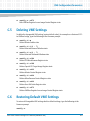
Displaying VME Settings . . . . . . . . . . . . . . . . . . . . . . . . . . . . . . . . . . . . . . . . . . . . . . . . . . . . . . . . . . . . 263
Editing VME Settings . . . . . . . . . . . . . . . . . . . . . . . . . . . . . . . . . . . . . . . . . . . . . . . . . . . . . . . . . . . . . . . 264
Deleting VME Settings . . . . . . . . . . . . . . . . . . . . . . . . . . . . . . . . . . . . . . . . . . . . . . . . . . . . . . . . . . . . . 265
Restoring Default VME Settings . . . . . . . . . . . . . . . . . . . . . . . . . . . . . . . . . . . . . . . . . . . . . . . . . . . . . 265
MOTLoad Firmware Package User’s Manual (6806800C24D)
Contents
D
Auto Boot . . . . . . . . . . . . . . . . . . . . . . . . . . . . . . . . . . . . . . . . . . . . . . . . . . . . . . . . . . . . . . . . . . . . . . . . . . 267
D.1
D.2
D.3
E
Safe Start and Alternate Boot Image . . . . . . . . . . . . . . . . . . . . . . . . . . . . . . . . . . . . . . . . . . . . . . . . . . . 271
E.1
E.2
E.3
E.4
E.5
E.6
F
Overview . . . . . . . . . . . . . . . . . . . . . . . . . . . . . . . . . . . . . . . . . . . . . . . . . . . . . . . . . . . . . . . . . . . . . . . . . 267
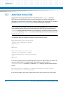
Auto Boot From a Disk . . . . . . . . . . . . . . . . . . . . . . . . . . . . . . . . . . . . . . . . . . . . . . . . . . . . . . . . . . . . . 268
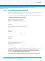
Auto Boot From the Network . . . . . . . . . . . . . . . . . . . . . . . . . . . . . . . . . . . . . . . . . . . . . . . . . . . . . . . 269
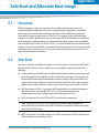
Overview . . . . . . . . . . . . . . . . . . . . . . . . . . . . . . . . . . . . . . . . . . . . . . . . . . . . . . . . . . . . . . . . . . . . . . . . . 271
Safe Start . . . . . . . . . . . . . . . . . . . . . . . . . . . . . . . . . . . . . . . . . . . . . . . . . . . . . . . . . . . . . . . . . . . . . . . . . 271
Alternate Boot Images . . . . . . . . . . . . . . . . . . . . . . . . . . . . . . . . . . . . . . . . . . . . . . . . . . . . . . . . . . . . . 272
Firmware Startup Sequence . . . . . . . . . . . . . . . . . . . . . . . . . . . . . . . . . . . . . . . . . . . . . . . . . . . . . . . . 272
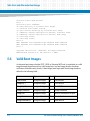
Firmware Scan for Boot Image . . . . . . . . . . . . . . . . . . . . . . . . . . . . . . . . . . . . . . . . . . . . . . . . . . . . . . 273
Valid Boot Images . . . . . . . . . . . . . . . . . . . . . . . . . . . . . . . . . . . . . . . . . . . . . . . . . . . . . . . . . . . . . . . . . 274
E.6.1 Checksum Algorithm . . . . . . . . . . . . . . . . . . . . . . . . . . . . . . . . . . . . . . . . . . . . . . . . . . . . . . . . 275
E.6.2 Boot Image Flags. . . . . . . . . . . . . . . . . . . . . . . . . . . . . . . . . . . . . . . . . . . . . . . . . . . . . . . . . . . . 275
E.6.3 Board State Requirements . . . . . . . . . . . . . . . . . . . . . . . . . . . . . . . . . . . . . . . . . . . . . . . . . . . 277
E.6.4 Alternate Boot Data Structure . . . . . . . . . . . . . . . . . . . . . . . . . . . . . . . . . . . . . . . . . . . . . . . . 278
Related Documentation . . . . . . . . . . . . . . . . . . . . . . . . . . . . . . . . . . . . . . . . . . . . . . . . . . . . . . . . . . . . . . 279
F.1
F.2
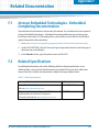
Artesyn Embedded Technologies - Embedded Computing Documentation . . . . . . . . . . . . . . . 279
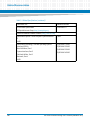
Related Specifications . . . . . . . . . . . . . . . . . . . . . . . . . . . . . . . . . . . . . . . . . . . . . . . . . . . . . . . . . . . . . . 279
MOTLoad Firmware Package User’s Manual (6806800C24D)
9
Contents
Contents
10
MOTLoad Firmware Package User’s Manual (6806800C24D)
List of Tables
Table 3-1
Table B-1
Table E-1
Table F-1
MOTLoad Commands . . . . . . . . . . . . . . . . . . . . . . . . . . . . . . . . . . . . . . . . . . . . . . . . . . . . . . . . . . 35
Command/Response Error Codes . . . . . . . . . . . . . . . . . . . . . . . . . . . . . . . . . . . . . . . . . . . . . . . 256
MOTLoad Image Flags . . . . . . . . . . . . . . . . . . . . . . . . . . . . . . . . . . . . . . . . . . . . . . . . . . . . . . . . . 275
Related Specifications . . . . . . . . . . . . . . . . . . . . . . . . . . . . . . . . . . . . . . . . . . . . . . . . . . . . . . . . . 279
MOTLoad Firmware Package User’s Manual (6806800C24D)
11
List of Tables
12
MOTLoad Firmware Package User’s Manual (6806800C24D)
About this Manual
Overview of Contents
The MOTLoad Firmware Package User’s Manual provides information on the MOTLoad
firmware. It is intended to be used in conjunction with a specific Artesyn board level product,
on which this firmware resides, such as the MVME5500, MVME3100, MVME6100, MVME7100,
ATCA-F102, and ATCA-C110. This manual provides general information on how to use the
firmware, as well as a detailed description of each command. It also provides information on
special features provided by MOTLoad (see Appendices).
This manual is divided into the following chapters and appendices.
Chapter 1, Introduction, includes an overview of the MOTLoad firmware, a brief description
of the firmware’s implementation and memory requirements, command types, utility
applications and tests
Chapter 2, Using MOTLoad, provides instructions on how to interact with the firmware
including a description of the command line interface, encompassing command line help
and command line rules; command history buffer, encompassing pseudo-VI Mode;
command line execution modes and MOTLoad manual page formats.
Chapter 3, MOTLoad Commands, provides a list of all current MOTLoad commands followed
by a detailed description of each command.
Appendix A, MOTLoad Non-Volatile Data, provides a description of the various types of nonvolatile data: VPD, GEV and SPD. Explanations and examples of existing VPD and GEV
commands are also provided. SPD is not covered at this time.
Appendix B, Remote Start, describes the remote interface provided by MOTLoad to the host
CPU via the backplane bus, which allows the host to obtain information about the target
board, download code and/or data, modify memory, and execute a downloaded program.
Appendix C, VME Configuration Parameters, describes how to manage VME configuration
parameters for VME-based products.
Appendix D, Auto Boot, provides information on how to auto boot an operating system
where no console is required.
Appendix E, Safe Start and Alternate Boot Image, describes MOTLoad’s Safe Start
mechanism and Alternate Boot Image support that enable customers to recover from
inadvertent board configurations.
Appendix F, Related Documentation, lists various documents related to specific devices and
industry specifications that are used in conjunction with the MOTLoad product.
MOTLoad Firmware Package User’s Manual (6806800C24D)
13
About this Manual
About this Manual
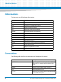
Abbreviations
This document uses the following abbreviations:
Abbreviation
Definition
BOOTP
Bootstrap Protocol
DHCP
Dynamic Host Configuration Protocol
GEV
Global Environment Variable
IBCA
Inter-Board Communication Address
NVRAM
Non-Volatile Random Access Memory
PCI
Peripheral Component Interconnect
POST
Power -On Self Test
RTC
Real-Time Clock
SBC
Single Board Computer
SDRAM
Synchronous Dynamic Random Access Memory
SPD
Serial Presence Defect
VME
VMEbus (Versa Module Euro Card)
VPD
Vital Product Data
Conventions
The following table describes the conventions used throughout this manual.
14
Notation
Description
0x00000000
Typical notation for hexadecimal numbers (digits are
0 through F), for example used for addresses and
offsets
0b0000
Same for binary numbers (digits are 0 and 1)
bold
Used to emphasize a word
Screen
Used for on-screen output and code related elements
or commands in body text
MOTLoad Firmware Package User’s Manual (6806800C24D)
About this Manual
Notation
Description
Courier + Bold
Used to characterize user input and to separate it
from system output
Reference
Used for references and for table and figure
descriptions
File > Exit
Notation for selecting a submenu
<text>
Notation for variables and keys
[text]
Notation for software buttons to click on the screen
and parameter description
...
Repeated item for example node 1, node 2, ..., node
12
.
Omission of information from example/command
that is not necessary at the time being.
.
.
..
Ranges, for example: 0..4 means one of the integers
0,1,2,3, and 4 (used in registers).
|
Logical OR.
Indicates a hazardous situation which, if not avoided,
could result in death or serious injury.
Indicates a hazardous situation which, if not avoided,
may result in minor or moderate injury
Indicates a property damage message.
No danger encountered. Pay attention to important
information.
MOTLoad Firmware Package User’s Manual (6806800C24D)
15
About this Manual
About this Manual
Summary of Changes
This manual has been revised and replaces all prior editions.
Date
Change
February 2015
Re-branded to Artesyn template.
March 2009
The following command was added to Chapter 3: csUserAltBoot
April 2008
These commands were added to Chapter 3: wait and waitProbe.
March 2008
The following commands were added to Chapter 3: mpuFork, mpuShow,
mpuStart, wait. New GEV descriptions added to Appendix A, MOTLoad NonVolatile Data.
Update to Emerson style.
June 2007
Added
-n
option to the netBoot command. Added Network I/O error codes to tftpGet,
tftpPut, netBoot, and ping commands.
June 2006
Added new commands in support of the ATCA-C110 blade: docBoot,
docProgram, docRead, and testDocHwInt,
April 2006
The
-r
option of the testSuite command was updated
16
Two commands were added to Chapter 3: flashLock and flashUnlock.
diskBoot command was updated.
New appendices added: Appendix C, VME Configuration Parameters and
Appendix E, Safe Start and Alternate Boot Image.
MOTLoad Firmware Package User’s Manual (6806800C24D)
About this Manual
Date
June 2004
July 2003
Change
A Standard Error Codes and Devices section was added to Chapter 2.
The following tests and commands were added to Chapter 3:
testThermoOp, testThermoQ, testThermoRange, csb csh csw and devShow.
A note was added to all memory tests, for example, testRam, specifying
how the memory is tested.
An error message field was added to applicable MOTLoad commands in
Chapter 3, MOTLoad Commands.
A warning was added to testDisk about being destructive.
The following commands were deleted from Chapter 3: mpuFork,
mpuShow, mpuSwitch, testFlash, testI2cRomRd, testI2cRomRdWr,
testUsbOscillator, and testUsbVok.
A Reserved GEVs section was added to Appendix A.
Auto boot instructions were added as an appendix, Appendix D, Auto Boot
The MOTLoad prompt throughout this document was changed to a generic
MOTLoad> from a specific product prompt, which will vary depending upon
which product was purchased.
Some command descriptions were modified and added to Chapter 3, as well
as corrections to font and text throughout to reflect more accurately screen
displays.
MOTLoad Firmware Package User’s Manual (6806800C24D)
17
About this Manual
18
About this Manual
MOTLoad Firmware Package User’s Manual (6806800C24D)
Chapter 1
Introduction
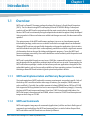
1.1
Overview
MOTLoad is a PowerPC firmware package developed for Artesyn’s Single Board Computers
(SBCs). The first boards using MOTLoad employ a Marvell GT64260A bridge. Subsequent
products will use MOTLoad in conjunction with the most recent industry designed bridge
devices. MOTLoad is continuously being developed and extended to support newly developed
Artesyn products. When new features are added and changes are made, this document will be
updated.
The main purpose of the MOTLoad firmware package is to serve as a board power-up and
initialization package, and to serve as a vehicle from which user applications can be booted.
Although MOTLoad was not specifically designed as a diagnostics application, the test suites
and the individual tests (with their various options) provide the user with a significant amount
of information that can be used for debug and diagnostic purposes. To use the MOTLoad
firmware package successfully, the reader should have some familiarity with the product and
firmware methodology.
MOTLoad is controlled through an easy to use, UNIX-like, command line interface. Its format
was designed with the application-oriented needs of the end user in mind. Consequently, the
MOTLoad software package is similar to that of many end-user applications designed for the
embedded market, such as the currently available real-time operating systems. Functionally,
this design allows MOTLoad to detect typical system level product devices.
1.1.1
MOTLoad Implementation and Memory Requirements
The implementation of MOTLoad and its memory requirements are product specific. Each of
the Artesyn SBCs are offered with a wide range of memory (for example, DRAM, external
cache, and flash). Typically, the smallest amount of onboard DRAM that an SBC has is 32 MB.
Each supported Artesyn product line has its own unique MOTLoad binary image(s). Currently
the largest MOTLoad compressed image is less than 1 MB. During board initialization, the
MOTLoad image is decompressed into DRAM, where it executes. A MOTLoad decompressed
image can be as large as 2.5 MB.
1.1.2
MOTLoad Commands
MOTLoad supports two groups of commands (applications): utilities and tests. Both types of
commands are invoked from the MOTLoad command line in a similar fashion. Beyond that,
MOTLoad utilities and MOTLoad tests are distinctly different.
MOTLoad Firmware Package User’s Manual (6806800C24D)
19
Introduction
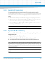
1.1.3
MOTLoad Utility Applications
The definition of a MOTLoad utility application is very broad. Simply stated, it is a MOTLoad
command that is not a MOTLoad test. Typically, MOTLoad utility applications are applications
that aid the user in some way. From the perspective of MOTLoad, examples of utility
applications are: configuration, data/status displays, data manipulation, help routines,
data/status monitors, and so on.
Operationally, MOTLoad utility applications differ from MOTLoad test applications in several
ways:
1.1.4
Only one utility application may be operating at any given time (that is, multiple utility
applications can not be executing concurrently).
Utility applications may interact with the user. Most test applications do not.
MOTLoad Tests
A MOTLoad test application determines whether or not the hardware meets a given standard.
Test applications are validation tests. Validation is conformance to a specification. Most
MOTLoad tests are designed to directly validate the functionality of a specific SBC subsystem
or component. It is possible for a board's component to fail in the user application but pass
specification conformance. These tests validate the operation of such SBC modules as:
dynamic memory, external cache, NVRAM, real time clock, and so on.
All MOTLoad tests are designed to validate functionality with minimum user interaction. Once
launched, most MOTLoad tests operate automatically without any user interaction. There are
a few tests where the functionality being validated requires user interaction (that is, switch
tests, interactive plug-in hardware modules, and so on). Most MOTLoad test results (errordata/status-data) are logged, not printed. Test results are not preserved and therefore not
available to user applications subsequent to their execution. All MOTLoad tests/commands are
described in detail in Chapter 3, MOTLoad Commands.
All devices that are available to MOTLoad for validation/verification testing are represented by
a unique device path string. Most MOTLoad tests require the operator to specify a test device
at the MOTLoad command line when invoking the test.
20
MOTLoad Firmware Package User’s Manual (6806800C24D)
Introduction
A listing of all device path strings can be displayed through the devShow command. If a SBC
device does not have a device path string it is not supported by MOTLoad and can not be
directly tested. There are a few exceptions to the device path string requirement, like testing
RAM, which is not considered a true device and can be directly tested without a device path
string. Refer to the devShow command page in this manual for more information.
Most MOTLoad tests can be organized to execute as a group of related tests (a test suite)
through the use of the testSuite command. The expert operator can customize their
testing by defining and creating a custom test suite(s). The list of built-in and user defined
MOTLoad test suites, and their test contents, can be obtained by entering: testSuite –d at
the MOTLoad prompt. All test suites that are included as part of a product specific MOTLoad
firmware package are product specific. For more information refer to the testSuite
command page in this manual.
Test results and test status are obtained through the testStatus, errorDisplay, and
taskActive commands. Refer to the appropriate command page(s) in this manual for more
information.
MOTLoad Firmware Package User’s Manual (6806800C24D)
21
Introduction
22
MOTLoad Firmware Package User’s Manual (6806800C24D)
Chapter 2
Using MOTLoad
2.1
Overview
This chapter describes various command line characteristics, as well as the MOTLoad Manual
Page Format.
Interaction with MOTLoad is performed via a command line interface through a serial port on
the SBC, which is connected to a terminal or terminal emulator (for example, Window’s
Hypercomm). The default MOTLoad serial port settings are: 9600 baud, 8 bits, no parity.
2.1.1
Command Line Interface
The MOTLoad command line interface is similar to a UNIX command line shell interface.
Commands are initiated by entering a valid MOTLoad command (a text string) at the MOTLoad
command line prompt and pressing the carriage-return key to signify the end of input.
MOTLoad then performs the specified action. The MOTLoad command line prompt is shown
below.
Note: The generic command prompt designation of MOTLoad is for documentation purposes
only. The exact command prompt designation is determined by the product being purchased,
for example, MVME6100, MVME5500, and so on.
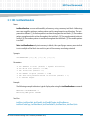
If an invalid MOTLoad command is entered at the MOTLoad command line prompt, MOTLoad
displays a message that the command was not found.
Example:
MOTLoad>
mytest
"mytest" not found
MOTLoad>
If the user enters a partial MOTLoad command string that can be resolved to a unique valid
MOTLoad command and presses the carriage-return key, the command will be executed as if
the entire command string had been entered. This feature is a user input shortcut that
minimizes the required amount of command line input. MOTLoad is an ever changing firmware
package, so user input shortcuts may change as command additions are made.
MOTLoad>
MOTLoad Firmware Package User’s Manual (6806800C24D)
23
Using MOTLoad
Example:
MOTLoad>
version
Copyright: Motorola Inc. 1999-2003, All Rights Reserved
MOTLoad RTOS Version 2.0
PAL Version 1.1 RM01
Mon Mar 10 12:01:28 MST 2003
Example:
MOTLoad>
ver
Copyright: Motorola Inc. 1999-2003, All Rights Reserved
MOTLoad RTOS Version 2.0
PAL Version 1.1 RM01
Mon Mar 10 12:01:28 MST 2003
If the partial command string cannot be resolved to a single unique command, MOTLoad will
inform the user that the command was ambiguous.
Example:
MOTLoad>
te
"te" ambiguous
MOTLoad>
2.1.2
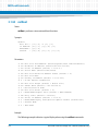
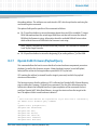
Command Line Help
Each MOTLoad firmware package has an extensive, product specific, help facility that can be
accessed through the help command. The user can enter help at the MOTLoad command line
to display a complete listing of all available tests and utilities.
Example:
MOTLoad>
24
MOTLoad Firmware Package User’s Manual (6806800C24D)
Using MOTLoad
help
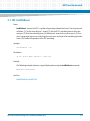
For help with a specific test or utility, the user can enter:
help
<command_name> at the MOTLoad prompt. The
help
command also supports a limited form of pattern matching. Refer to the
help
command page.
Example:
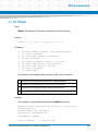
MOTLoad>
help testRam
Usage: testRam [-aPh] [-bPh] [-iPd] [-nPh] [-tPd] [-v]
Description: RAM Test Directory
Argument/Option Description
-a Ph: Address to Start (Default = Dynamic Allocation)
-b Ph: Block Size (Default = 16 MB)
-i Pd: Iterations (Default = 1)
-n Ph: Number of Bytes (Default = 1 MB)
-t Ph: Time Delay Between Blocks in OS Ticks (Default = 1)
-v 0: Verbose Output
MOTLoad>
2.1.3
Command Line Rules
There are a few things to remember when entering a MOTLoad command:
Multiple commands are permitted on a single command line, provided they are separated
by a single semicolon(";").
Spaces separate the various fields on the command line (command/arguments/options).
The argument/option identifier character is always preceded by a hyphen (“-”) character
MOTLoad Firmware Package User’s Manual (6806800C24D)
25
Using MOTLoad
Options are identified by a single character
Option arguments immediately follow (no spaces) the option
All commands, command options, device tree strings, and so on are case sensitive
Example:
MOTLoad> flashProgram –d/dev/flash0 –n00100000
2.1.4
Command History Buffer
MOTLoad saves command line inputs into a command history buffer. Up to 128 previously
entered commands can be recalled, edited, and reentered at the command line. Once the
desired command appears on the command line it can be re-executed by pressing the
carriage-return key.
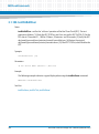
2.1.5
pseudo-Vi Mode
MOTLoad supports a pseudo-VI editor command recall through the ESC and the j and k keys.
Typing
ESC
and then
k
moves backwards through the history command buffer and displays the preceding
commands. Typing
ESC
and then
j
moves forward through the history command buffer and displays the more recent commands.
After the
ESC
26
MOTLoad Firmware Package User’s Manual (6806800C24D)
Using MOTLoad
key is pressed, the
j
and/or
k
key may be pressed as often as needed to bring up the desired command from the command
history buffer.
2.1.6
Command Line Execution Modes
MOTLoad utilities such as help always execute in the foreground. MOTLoad tests can be
executed in the foreground (sequentially) or in the background (concurrently) as background
tasks.
Note Not all tests can execute in background mode. As an example, cache tests must run in
the foreground.
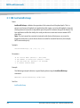
When a sequential test starts executing in the foreground, no new MOTLoad tests can execute
until the current test running in the foreground is complete. This does not apply to background
tests.
Example:
MOTLoad>
testRam
In concurrent test mode, each test gets a time sliced share of the CPU execution time. The
amount of user control over the background task time slicing operations is determined by the
underlying OS. The operator specifies concurrent test execution by ending the test command
line with the ampersand (&) character (prior to the carriage-return). The MOTLoad command
prompt reappears after a concurrent test is started.
Example:
MOTLoad>
testRam &
MOTLoad Firmware Package User’s Manual (6806800C24D)
27
Using MOTLoad
After the MOTLoad prompt reappears, another test or utility may be started (in the foreground
or background execution mode) as long as it does not interfere (use the same computer
resources) with the operations of other test(s) running in background mode. The test
execution status of a test(s) running in background mode can be monitored through the use
of the taskActive and testStatus commands. Refer to the appropriate man pages for
more details.
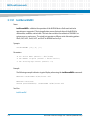
2.1.7
Copying/Transferring MOTLoad Images
Flash images can be copied between memory and flash, or between flash banks, by the use of
the flashProgram utility. Extreme care should be taken in this process to ensure that
accidental overwriting of the bootloader code and/or MOTLoad does not occur. It is advised
that you never program the boot block of the active flash bank (the one from which the board
was booted). This ensures that the bootloader image is never overwritten by flashProgram.
The bootloader resides in the boot block of each flash bank. If both images have been
overwritten, the board may be unbootable. Further, since flashProgram is a component
within MOTLoad, the user is not able to reprogram (reflash) the boot block to effect recovery.
The utility flashShow indicates which flash bank is the active flash bank and provides its base
address and size. Also refer to the Programmer’s Reference Guide and/or Installation and Use
manual for your board.
The boot block is the last (highest address) 1 MB of a flash bank. flashProgram writes to an
offset from the base (lowest address) of a flash bank. The source for the image being
programmed can be any addressable memory; for example, SDRAM, NVRAM, or flash.
28
MOTLoad Firmware Package User’s Manual (6806800C24D)
Using MOTLoad
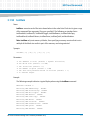
2.2
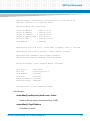
MOTLoad Command Description Page Format
All MOTLoad command pages follow the format described below.
Name
This field names the test or utility as it would appear on the MOTLoad command line. It also
provides a description of the command, for example:
errorDisplay - displays the Contents of the MOTLoad Test Error Status Table
Synopsis
This field shows command line usage or syntax of a command, test, or utility. This consists
of the name of the command, test or utility, and a list of all possible arguments/options, for
example:
errorDisplay [-eP*] [-nP*] [-sP*]
If an argument is optional, it is enclosed in a set of braces [ ], otherwise it is required.
If an asterisk (*) or other symbol follows an option, another argument is required with that
option.
The asterisk (*) symbol means that a number of valid numeric base conversion option
arguments are possible. Refer to the table titled Number Base Specifiers for more
information.
An attempt has been made to standardize the meaning of option arguments but the exact
meaning of an option and its arguments is test specific. Exact option information can be
displayed through the use of the help command or by referring the appropriate man page.
Parameter
This field describes each argument and option of the command, for example:
MOTLoad Firmware Package User’s Manual (6806800C24D)
29
Using MOTLoad
-a P*: Executive Process/Task Identifier of Entry to Display
-n P*: Number of Entries to Display
-s P*: Specific Entry Number (1 to n) to Display
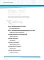
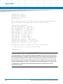
Example
This field shows how the command, test, or utility is typically used. The command line
invocation of the command, test, or utility and the subsequent displayed results are
shown. In some cases extensive examples are provided, for example:
MOTLoad> errorDisplay
tName =testDisk -d/dev/ide0/hdisk2 -n5000
sPID=00000011 ePID=00000014 eS.eM = 2.1 entryNo = 00000001
sErrNo=00000000 eErrNo=0C0000002C errCnt=00000001 loopCnt-00000000
sTime=43:48:15 fTime=43:48:15 eTime=00:00:00 1Time=15:51:54
Error Messages:
Data Comparison Failure in Block Range 0-255
Write/Read Date: 05F0436F/00000000
Write/Read Address: 008E1000/00*C0000
Device-Name =/dev/ide0/hdisk2
Error Messages
This field shows the known error messages output by MOTLoad. This field is only
applicable to commands, not tests.
Assembler Error:error code = <value>
Error code not in table
See Also
This field lists tests/utilities that are functionally related to the described command, for
example: clear, testStatus
30
MOTLoad Firmware Package User’s Manual (6806800C24D)
Using MOTLoad
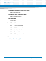
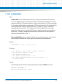
2.3
User Download Buffer
In order to accommodate for the storage of data generated by one or more MOTLoad
commands that are not given a specific memory path or location, MOTLoad employs a
temporary memory buffer, known as the User Download Buffer.
The size of the User Download Buffer is 2 MB. Commands will fail if the user attempts to load
more than 2 MB into the buffer. In cases where more than 2 MB are needed, the user should
use the malloc command (malloc <size>) to create a buffer of suitable size.
Typing malloc <size> on the command line where size is the number of bytes requested
causes MOTLoad to allocate an area of RAM that can be used by the user. The address of the
start of the RAM buffer area is returned to the user. An address of "0" indicates that the
request failed.
2.4
Standard Error Codes and Devices
This section describes error message formats and a generalized listing of error number (errno)
values. As with any code application, MOTLoad is continually being revised and new error
messages may appear.
MOTLoad Firmware Package User’s Manual (6806800C24D)
31
Using MOTLoad
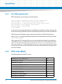
2.4.1
Error Message Formats
MOTLoad displays error messages in one of six formats:
function_name():
function_name():
function_name():
function_name():
function_name():
error_messsage
open(<device_name>) failed, errno=<value>
ioctl(<value>) failed, errno=<value>
io_operation([device]) failed, errno=<value>
error_message, errno=<value>
error_message
In some cases, the message format may vary slightly from the above. For these messages, the
format and meaning is identified under the Error Messages section for the affected command.
When the operation attempts to open a device but encounters a failure during the open
process, the open message is displayed and identifies the complete device name (for example,
/dev/ide0/hdisk0).
When a general IOCTL command fails, the ioctl value identifies the failing I/O operation of a
specific device type; for example, block, terminal, tape, and so on. For an example set of IOCTL
codes, refer to the IOCTL Codes (Block) table (below). It is not necessary to know all the codes
for each type of device since the individual error message sections define the meaning of each
ioctl error message.
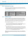
2.4.2
IOCTL Codes (Block)
The following table lists the IOCTL codes:
32
IOBLOCK_IOCTL_GET_DEVICE_TYPE
100
IOBLOCK_IOCTL_STATUS
101
IOBLOCK_IOCTL_RESET
102
IOBLOCK_IOCTL_GET_BLOCK_SIZE
103
IOBLOCK_IOCTL_NBLOCKS
104
IOBLOCK_IOCTL_FORMAT
105
IOBLOCK_IOCTL_SEEK_SET
106
IOBLOCK_IOCTL_SEEK_CURRENT
107
IOBLOCK_IOCTL_SEEK_END
108
MOTLoad Firmware Package User’s Manual (6806800C24D)
Using MOTLoad
IOBLOCK_IOCTL_DISK_CHANGE
109
IOBLOCK_IOCTL_MOTOR_ON
110
IOBLOCK_IOCTL_MOTOR_OFF
111
IOBLOCK_IOCTL_BSEEK_SET
112
IOBLOCK_IOCTL_BSEEK_CURRENT
113
IOBLOCK_IOCTL_BSEEK_END
114
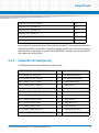
Error numbers (errno) can be derived from either the standard I/O error codes as listed in the
Standard Error Codes (errno) table or from driver-/device-specific errors. Error codes unique to
either the driver or the device are greater than 0x00010000. Currently, only the standard I/O
error codes are used for utilities.
2.4.3
Standard Error Codes (errno)
The following table lists the standard error codes (errno):
IOSTD_ERROR_DEVICE_NOT_FOUND
1
/* device not found */
IOSTD_ERROR_FD_TABLE_FULL
2
/* file descriptor table full */
IOSTD_ERROR_FD_NOT_FOUND
3
/* file descriptor not found */
IOSTD_ERROR_FD_NOT_VALID
4
/* invalid file descriptor */
IOSTD_ERROR_MODE_CONFLICT
5
/* mode conflict */
IOSTD_ERROR_ILLEGAL_REQUEST
6
/* illegal request */
IOSTD_ERROR_DEVICE_TYPE_INVALID
7
/* invalid device type */
IOSTD_ERROR_DEVICE_TYPE_UNKNOWN
8
/* unknown device type */
IOSTD_ERROR_DEVICE_LOCKED
9
/* device locked */
IOSTD_ERROR_DEVICE_WRITE
10
/* device write error */
IOSTD_ERROR_DEVICE_READ
11
/* device read error */
IOSTD_ERROR_UNKNOWN_IOCTL
12
/* unknown ioctl function */
IOSTD_ERROR_OWNERSHIP
13
/* ownership failure */
MOTLoad Firmware Package User’s Manual (6806800C24D)
33
Using MOTLoad
34
MOTLoad Firmware Package User’s Manual (6806800C24D)
Chapter 3
MOTLoad Commands
3.1
Overview
This chapter lists the current valid MOTLoad commands. The remainder of the chapter
describes each command in detail.
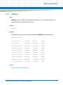
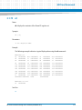
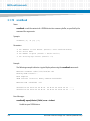
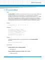
3.1.1
MOTLoad Command List
The following table provides a list of all current MOTLoad commands. Products supported by
MOTLoad may or may not employ the full command set. Typing help at the MOTLoad
command prompt displays all commands supported by MOTLoad for a given product.
Note The command prompt designation for this manual is MOTLoad; however, the command
prompt for your specific version of MOTLoad is the product designator for your particular
board, for example, MVME6100, MVME5500.
Table 3-1 MOTLoad Commands
Command
Description
as
One-Line Instruction Assembler
bcb bch bcw
Block Compare Byte/Halfword/Word
bdTempShow
Display Current Board Temperature
bfb bfh bfw
Block Fill Byte/Halfword/Word
blkCp
Block Copy
blkFmt
Block Format
blkRd
Block Read
blkShow
Block Show Device Configuration Data
blkVe
Block Verify
blkWr
Block Write
bmb bmh bmw
Block Move Byte/Halfword/Word
br
Assign/Delete/Display User-Program Break-Points
bsb bsh bsw
Block Search Byte/Halfword/Word
bvb bvh bvw
Block Verify Byte/Halfword/Word
MOTLoad Firmware Package User’s Manual (6806800C24D)
35
MOTLoad Commands
Table 3-1 MOTLoad Commands (continued)
36
Command
Description
cdDir
ISO9660 File System Directory Listing
cdGet
ISO9660 File System File Load
clear
Clear the Specified Status/History Table(s)
cm
Turns on Concurrent Mode (connect to Host)
csb csh csw
Calculates a Checksum Specified by Command-line Options
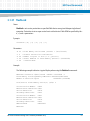
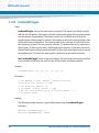
csUserAltBoot
Checksums user boot images specified in the alternate boot image header
at the beginning of files to be programmed into flash memory.
devShow
Display (Show) Device/Node Table
diskBoot
Disk Boot (Direct-Access Mass-Storage Device)
docBoot
Boots the kernel image stored in the binary partition of the Disk on Chip
(DoC)
docProgram
Programs an image residing in the RAM into the binary partition of the DoC
docRead
Reads the contents of the specified binary partition into the RAM
downLoad
Down Load S-Record from Host
ds
One-Line Instruction Disassembler
echo
Echo a Line of Text
elfLoader
ELF Object File Loader
errorDisplay
Display the Contents of the Test Error Status Table
eval
Evaluate Expression
execProgram
Execute Program
fatDir
FAT File System Directory Listing
fatGet
FAT File System File Load
fdShow
Display (Show) File Descriptor
flashLock
Set Sector Protection on Specified Flash Device
flashProgram
Flash Memory Program
flashShow
Display Flash Memory Device Configuration Data
flashUnlock
Clears Sector Protection on Specified Flash Device
gd
Go Execute User-Program Direct (Ignore Break-Points)
MOTLoad Firmware Package User’s Manual (6806800C24D)
MOTLoad Commands
Table 3-1 MOTLoad Commands (continued)
Command
Description
gevDelete
Global Environment Variable Delete
gevDump
Global Environment Variable(s) Dump (NVRAM Header + Data)
gevEdit
Global Environment Variable Edit
gevInit
Global Environment Variable Area Initialize (NVRAM Header)
gevList
Lists the Global Environment Variables
gevShow
Global Environment Variable Show
gn
Go Execute User-Program to Next Instruction
go
Go Execute User-Program
gt
Go Execute User-Program to Temporary Break-Point
hbd
Display History Buffer
hbx
Execute History Buffer Entry
help
Display Command/Test Help Strings
l2CacheShow
Display state of L2 Cache and L2CR register contents
l3CacheShow
Display state of L3 Cache and L3CR register contents
mdb mdh mdw
Memory Display Bytes/Half words/Words
memShow
Display Memory Allocation
mmb mmh mmw
Memory Modify Bytes/Half words/Words
mpuFork
Execute program from idle processor
mpuShow
Display multi-processor control structure
mpuStart
Start the other MPU
netBoot
Network Boot (BOOT/TFTP)
netShow
Display Network Interface Configuration Data
netShut
Disable (Shutdown) Network Interface
netStats
Display Network Interface Statistics Data
noCm
Turns off Concurrent Mode
pciDataRd
Read PCI Device Configuration Header Register
pciDataWr
Write PCI Device Configuration Header Register
MOTLoad Firmware Package User’s Manual (6806800C24D)
37
MOTLoad Commands
Table 3-1 MOTLoad Commands (continued)
38
Command
Description
pciDump
Dump PCI Device Configuration Header Register
pciShow
Display PCI Device Configuration Header Register
pciSpace
Display PCI Device Address Space Allocation
ping
Ping Network Host
portSet
Port Set
portShow
Display Port Device Configuration Data
rd
User Program Register Display
reset
Reset System
rs
User Program Register Set
set
Set Date and Time
sromRead
SROM Read
sromWrite
SROM Write
sta
Symbol Table Attach
stl
Symbol Table Lookup
stop
Stop Date and Time (Power-Save Mode)
taskActive
Display the Contents of the Active Task Table
tc
Trace (Single-Step) User Program
td
Trace (Single-Step) User Program to Address
testDisk
Test Disk
testDocHwInt
Verifies the hardware connectivity of the DoC by reading and verifying the
chip ID
testEnetPtP
Ethernet Point-to-Point
testNvramRd
NVRAM Read
testNvramRdWr
NVRAM Read/Write (Destructive)
testRam
RAM Test (Directory)
testRamAddr
RAM Addressing
testRamAlt
RAM Alternating
MOTLoad Firmware Package User’s Manual (6806800C24D)
MOTLoad Commands
Table 3-1 MOTLoad Commands (continued)
Command
Description
testRamBitToggle
RAM Bit Toggle
testRamBounce
RAM Bounce
testRamCodeCopy
RAM Code Copy and Execute
testRamEccMonitor
Monitor for ECC Errors
testRamMarch
RAM March
testRamPatterns
RAM Patterns
testRamPerm
RAM Permutations
testRamQuick
RAM Quick
testRamRandom
RAM Random Data Patterns
testRtcAlarm
RTC Alarm
testRtcReset
RTC Reset
testRtcRollOver
RTC Rollover
testRtcTick
RTC Tick
testSerialExtLoop
Serial External Loopback
testSerialIntLoop
Serial Internal Loopback
testStatus
Display the Contents of the Test Status Table
testSuite
Execute Test Suite
testSuiteMake
Make (Create) Test Suite
testThermoOp
Thermometer Temp Limit Operational Test
testThermoQ
Thermometer Temp Limit Quick Test
testThermoRange
Tests That Board Thermometer is Within Range
testWatchdogTimer
Watchdog Timer Device Accuracy Test
tftpGet
TFTP Get
tftpPut
TFTP Put
time
Display Date and Time
transparentMode
Transparent Mode (Connect to Host)
tsShow
Display Task Status
MOTLoad Firmware Package User’s Manual (6806800C24D)
39
MOTLoad Commands
Table 3-1 MOTLoad Commands (continued)
40
Command
Description
upLoad
Up Load Binary-Data from Target
version
Display Version String(s)
vmeCfg
Manages User-specified VME Configuration Parameters
vpdDisplay
VPD Display
vpdEdit
VPD Edit
wait
Wait for n Seconds or Until all Tests Complete
waitProbe
Wait for I/O Probe to Complete
MOTLoad Firmware Package User’s Manual (6806800C24D)
MOTLoad Commands
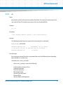
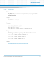
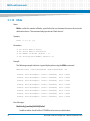
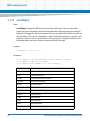
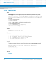
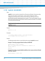
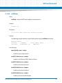
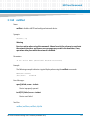
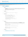
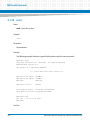
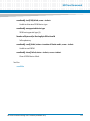
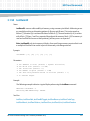
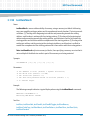
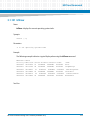
3.1.2
as
Name
as—provides access to the one-line assembler. By default, the memory location to place the
user entered PowerPC assembly instructions is the User Download Buffer.
Synopsis
as [-a]
Parameter
-a Ph: Assembly Address (Default = User Download Buffer)
Example
The following example depicts a typical result of entering the as command.
MOTLoad> as –a00560000
00560000 00000000 word
0x00000000? lwz r3, 0x0(x3)
-- the above line will be replaced with the following -00560000 80630000 lwz
r3,0x0(r3)
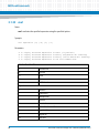
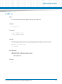
Error Messages
Error messages returned from the as command take one of the following forms depending
upon whether it is a known error.
Assembler Error: <error_message>
where <error_message> is one of the following:
An Operand has a Length of Zero
Unknown Mnemonic
Excessive Operand(s)
Missing Operand(s)
Operand Type Not Found
Operand Prefix
Operand Address Misalignment
MOTLoad Firmware Package User’s Manual (6806800C24D)
41
MOTLoad Commands
Operand Displacement
Operand Sign Extension
Operand Data Field Overflow
Operand Conversion
Operand Sign Extension
Operand Data Field Overflow
Operand Conversion
Assembler Error: error code = <value>
Undefined error return (<value>).
See Also
br, ds, gd, gn, go, gt, rd, rs, tc, td
42
MOTLoad Firmware Package User’s Manual (6806800C24D)
MOTLoad Commands
3.1.3
bcb bch bcw
Name
bcb, bch, bcw—compares the contents of two memory blocks as specified by the commandline options.
Synopsis
bcb/bch/bcw -a -b -c
Parameters
-a Ph: Starting Address of Block 1
-b Ph: Ending Address of Block 1
-c Ph: Starting Address of Block 2
Example
The following example shows a typical result of entering the bcw, bch, and bcb commands.
MOTLoad> bcw –a100000 –b100004 –c560000
00100000|7C3043A6 00560000|80630000
MOTLoad> bch –a100000 –b100004 –c560000
00100000|7C30
00100002|43A6
005600000|8063
005600002|0000
MOTLoad> bcb –a100000 –b100004 –c560000
00100000|7C
00100001|30
00100002|43
00100003|A6
00560000|80
00560001|63
00560002|00
00560003|00
See Also
bfb bfh bfw, bmb bmh bmw, bsb bsh bsw, bvb bvh bvw
MOTLoad Firmware Package User’s Manual (6806800C24D)
43
MOTLoad Commands
3.1.4
bdTempShow
Name
bdTempShow—displays the current board temperature(s). The information displayed may
vary dependent upon the hardware.
Synopsis
bdTempShow
Parameters
none
Example
The following example shows a typical result of entering the bdTempShow command:
MOTLoad> bdTempShow
Cpu TAU Temp=030C Therm Sensor = 27.0C
MOTLoad>
The TAU value has a variation of 25C; however, the DS1621 thermal sensor has an accuracy
of 0.5C. This sensor is usually located on the secondary side of the board, centered near the
lower edge.
See Also
44
MOTLoad Firmware Package User’s Manual (6806800C24D)
MOTLoad Commands
3.1.5
bfb bfh bfw
Name
bfb, bfh, bfw—fills the contents of a memory block with a pattern, as specified by the
command-line options.
Synopsis
bfb/bfh/bfw -a -b -d [-i]
Parameters
-a
-b
-d
-i
Ph:
Ph:
Ph:
Ph:
Starting Address of Block
Ending Address of Block
Fill Data Pattern
Fill Data Increment (Default = 00000000/0000/00)
Example
The following example shows a typical usage of the bfw, bfh and bfb commands:
MOTLoad> bfw –a100000 –b100004 –d00000004 –il
MOTLoad> bfh –a100000 –b100004 –d0008 –il
MOTLoad> bfb –a100000 –b100004 –dFF –il
See Also
bcb bch bcw, bmb bmh bmw, bsb bsh bsw, bvb bvh bvw
MOTLoad Firmware Package User’s Manual (6806800C24D)
45
MOTLoad Commands
3.1.6
blkCp
Name
blkCp—copies the number of blocks, specified by the user, from the device to the destination
device. This command only operates on ’block devices’.
Synopsis
blkCp -a -b [-n] [-s]
Parameters
-a
-b
-n
-s
Ps:
Ps:
Ph:
Ph:
Device Name of Source
Device Name of Destination
Number of Blocks (Default = 1)
Starting Block Number (Default = 0)
Example
The following example shows a typical result of entering the blkCP command:
MOTLoad> blkCp -a/dev/ide0/hdisk0 -b/dev/ide0/hdisk0 -n200
Error Messages
blockCopy(): malloc(0x20000) failed
Unable to malloc a local buffer of 128 KB.
blockCopy(): open(<filename>) failed, errno = <value>
Unable to open source/destination device/node.
blockCopy(): ioctl(103) failed, errno = <value>
Unable to retrieve the physical block size of the source/destination device.
blockCopy(): bseek() failed, errno = <value>
Seek to desired block (starting block of transfer) on source/destination.
46
MOTLoad Firmware Package User’s Manual (6806800C24D)
MOTLoad Commands
blockCopy(): unequal block sizes not supported
Block size of source device != that of destination.
blockCopy(): read() failed, status = <value>, errno = <value>
Read error on source device.
blockCopy(): write() failed, status = <value>, errno = <value>
Write error on destination device.
See Also
blkFmt, blkRd, blkShow, blkVe, blkWr
MOTLoad Firmware Package User’s Manual (6806800C24D)
47
MOTLoad Commands
3.1.7
blkFmt
Name
blkFmt—formats a block device specified by the user. This command only operates on ’block
devices’.
Synopsis
blkFmt [-d] [-i]
Parameters
-d Ps: Device Name (Default = /dev/fd0)
-i 0: Ignore Grown Defect List
Example
The following example shows a typical result when blkFmt is entered.
MOTLoad> blkFmt -d/dev/ide0/hdisk0
Error Messages
blockFormat(): open(<device/node name>) failed, errno = <value>
Failure on opening specified device/node.
blockFormat(): ioctl(105) failed, errno = <value>
Format command failed.
See Also
blkCp, blkRd, blkShow, blkVe, blkWr
48
MOTLoad Firmware Package User’s Manual (6806800C24D)
MOTLoad Commands
3.1.8
blkRd
Name
blkRd—reads the number of blocks, specified by the user, from the specified device to a
memory address. This command only operates on ’block devices’.
Synopsis
blkRd [-d] [-m] [-n] [-s] [-t]
Parameters
-d
-m
-n
-s
-t
Ps:
Ph:
Ph:
Ph:
0 :
Device Name (Default = /dev/fd0)
Memory Address (Default = User Download Buffer)
Number of Blocks (Default = 1)
Starting Block Number (Default = 0)
Display Elapsed Time
Example
The following examples shows a typical response from entering the blkRd command.
MOTLoad> blkRd -d/dev/ide0/hdisk0 -n20 -t
blkRd( ):
number of bytes
= 00004000 (&16384)
blkRd( ):
number of micro-seconds = 00004170 (&16752)
blkRd( ):
bytes/second
= (not measurable)
Error Messages
blockRead(): open(<device/node>) failed, errno = <value>
Unable to open input device.
blockRead(): ioctl(103) failed, errno = <value>
Unable to determine block size of device/node.
blockRead(): bseek() failed, errno = <value>
Unable to seek to specified starting block.
MOTLoad Firmware Package User’s Manual (6806800C24D)
49
MOTLoad Commands
blockRead(): read() failed, errno = <value>
Unable to read block from device/node.
See Also
blkCp, blkFmt, blkShow, blkVe, blkWr
50
MOTLoad Firmware Package User’s Manual (6806800C24D)
MOTLoad Commands
3.1.9
blkShow
Name
blkShow—displays all MOTLoad configured block devices. This command’s purpose is to
display all MOTLoad configured block devices.
Synopsis
blkShow
Examples
The following examples show a typical output when a blkShow command is entered.
MOTLoad> blkShow
Block-Device
N-Blocks
B-Size
Type
/dev/nvram
00007FF0
00000001
NVRAM
/dev/i2c/srom/90
00000002
00000001
SROM
/dev/i2c/srom/A0
00000100
00000001
SROM
/dev/i2c/srom/A2
00000100
00000001
SROM
/dev/i2c/srom/A4
00000100
00000001
SROM
/dev/i2c/srom/A6
00002000
00000001
SROM
/dev/i2c/srom/A8
00002000
00000001
SROM
/dev/i2c/srom/AA
00002000
00000001
SROM
/dev/ide0/hdisk2
026016F0
00000200
Disk
See Also
blkCp, blkFmt, blkRd, blkVe, blkWr
MOTLoad Firmware Package User’s Manual (6806800C24D)
51
MOTLoad Commands
3.1.10 blkVe
Name
blkVe—verifies the number of blocks, specified by the user, between the source device to the
destination device. This command only operates on ’block devices’.
Synopsis
blkVe -a -b [-n] [-s]
Parameters
-a
-b
-n
-s
Ps:
Ps:
Ph:
Ph:
Device Name of Source
Device Name of Destination
Number of Blocks (Default = 1)
Starting Block Number (Default = 0)
Example
The following example indicates a typical display when using the blkVe command.
MOTLoad> blkVe -a/dev/ide0/hdisk0 -b/dev/ide0/hdisk1 -n8
blkVe(): data miscompare:
offset = 00000000,
data = 80/05
blkVe(): data miscompare:
offset = 00000001,
data = 08/F0
blkVe(): data miscompare:
offset = 00000002,
data = 04/43
blkVe(): data miscompare:
offset = 00000003,
data = 0D/6F
blkVe(): data miscompare:
offset = 00000004,
data = 0A/03
blkVe(): data miscompare:
offset = 00000005,
data = 01/F5
blkVe(): data miscompare:
offset = 00000006,
data = 48/82
blkVe(): data miscompare:
offset = 00000007,
data = 00/4A
Error Messages
blockVerify(): malloc(0x20000) failed
Unable to malloc a local buffer of 128 KB for either source or destination.
52
MOTLoad Firmware Package User’s Manual (6806800C24D)
MOTLoad Commands
blockVerify(): open(<source/destination device/node>) failed, errno = <value>
Unable to open either source or destination device/node.
blockVerify(): ioctl(103) failed, errno = <value>
Unable to get block size of source/destination device/node.
blockVerify(): bseek() failed, errno = <value>
Unable to seek to either source/destination starting block number.
blockVerify(): unequal block sizes not supported
Block size of source and destination are not equal.
blockVerify(): read() failed, status = <value>, errno = <value>, device = <value>
Unable to read from either source/destination device/node.
See Also
blkCp, blkFmt, blkRd, blkShow, blkWr
MOTLoad Firmware Package User’s Manual (6806800C24D)
53
MOTLoad Commands
3.1.11 blkWr
Name
blkWr—writes the number of blocks, specified by the user, from the memory address to the
specified device. This command only operates on ’block devices’.
Synopsis
blkWr [-d] [-m] [-n] [-s] [-t]
Parameters
-d
-m
-n
-s
-t
Ps: Device Name (Default = /dev/fd0)
Ph: Memory Address (Default = User Download Buffer)
Ph: Number of Blocks (Default = 1)
Ph: Starting Block Number (Default = 0)
0: Display Elapsed Time
Example
The following example indicates a typical display when using the blkVe command.
MOTLoad>
blkWr():
blkWr():
blkWr():
blkWr -d/dev/ide0/hdisk0 -n20 -t
number of bytes
= 00004000 (&16384)
number of micro-seconds = 00000283 (&643)
bytes/second
= (not measurable)
Error Messages
blockWr(): open(<device/node>) failed, errno = <value>
Unable to open input device/node.
blockWrite(): ioctl(103) failed, errno = <value>
Unable to determine block size of device/node.
blockWrite(): bseek() failed, errno = <value>
Unable to seek to specified starting block.
54
MOTLoad Firmware Package User’s Manual (6806800C24D)
MOTLoad Commands
blockWrite(): write() failed, status = <value> errno = <value>
Unable to write to specified device/node.
See Also
blkCp, blkFmt, blkShow, blkVe, blkWr
MOTLoad Firmware Package User’s Manual (6806800C24D)
55
MOTLoad Commands
3.1.12 bmb bmh bmw
Name
bmb, bmh, bmw—moves (copies) the contents of a memory block from one location to
another, as specified by the command-line options.
Synopsis
bmb/bmh/bmw -aPh -bPh -cPh
Parameters
bmb
-a Ph:
-b Ph:
-c Ph:
bmh
-a Ph:
-b Ph:
-c Ph:
bmw
-a Ph:
-b Ph:
-c Ph:
Starting Address of Source Block
Ending Address of Block
Starting Address of Destination Block
Starting Address of Source Block (half-word aligned)
Addr of Last Source Half-Word to be copied (half-word aligned)
Starting Address of Destination Block
Starting Address of Source Block (word aligned)
Addr of Last Source Word to be copied (word aligned)
Starting Address of Destination Block
Example
The following example indicates a typical display when using the bmb, bmh, and bmw
commands.
MOTLoad> bmw -a00560000 -b00560020 -c00560040
MOTLoad> bmh -a00560000 -b00560020 -c00560040
MOTLoad> bmb -a00560000 -b00560020 -c00560040
See Also
bcb bch bcw, bfb bfh bfw, bsb bsh bsw, bvb bvh bvw
56
MOTLoad Firmware Package User’s Manual (6806800C24D)
MOTLoad Commands
3.1.13 br
Name
br—assigns, deletes, or displays user-program break points.
Synopsis
br [-a] [-c] [-d]
Parameters
-a Ph: Address
-c Pd: Count (Default = 0)
-d 0: Delete Specified/All Break-Points
Example
The following example indicates a typical display when using the bmb, bmh, and bmw
commands.
MOTLoad> br -a00100000 <---Adds a break-point
Address Count
Label
00100000 00000000 evtbl+0x000
MOTLoad>
Address
00100000
00100100
br
<---Displays all break-points
Count
Label
00000000 evtbl+0x000
00000002 evtbl+0x100
MOTLoad> br -a00100100 -d <---Deletes break-point at specified address
Address Count
Label
00100000 00000000 evtbl+0x000
MOTLoad> br -d
<---Deletes all break-points
See Also
as, ds, gd, gn, go, gt, rd, rs, tc, tc
MOTLoad Firmware Package User’s Manual (6806800C24D)
57
MOTLoad Commands
3.1.14 bsb bsh bsw
Name
bsb, bsh, bsw—searches the contents of a memory block for a specific data pattern, as
specified by the command-line options.
Synopsis
bsb/bsh/bsw -a -b -d [-n] [-z]
Parameters
-a
-b
-d
-n
-z
Ph: Starting Address of Block
Ph: Ending Address of Block
Ph: Search Data Pattern
0: Non-Matching Data (Default = Matching)
Ph: Search Data Mask (Default = FFFFFFFF/FFFF/FF)
Example
The following example indicates a typical display when using the bsb, bsh, and bsw
commands.
MOTLoad> bsw -a00560000 -b00560010 -d12345678
pattern not found
MOTLoad> bsw -a00560000 -b00560010 -d11111111
00560000|11111111
See Also
bcb bch bcw, bfb bfh bfw, bmb bmh bmw, bvb bvh bvw
58
MOTLoad Firmware Package User’s Manual (6806800C24D)
MOTLoad Commands
3.1.15 bvb bvh bvw
Name
bvb, bvh, bvw—verifies the contents of a memory block for a specific data pattern, as specified
by the command-line options. Only non-matching data patterns are displayed.
Synopsis
bvb/bvh/bvw -a -b -d [-i]
Parameters
-a
-b
-d
-i
Ph:
Ph:
Ph:
Ph:
Starting Address of Block
Ending Address of Block
Verify Data Pattern
Fill Data Increment (Default = 00000000/0000/00)
Example
The following example indicates a typical display when using the bsb, bsh, and bsw
commands.
MOTLoad> mdw -a00560000 -c4
00560000 11111111 22222222 33333333 44444444
MOTLoad> bvw -a00560000 -b00560010 -d22222222
00560000|11111111 00560008|33333333 0056000C|44444444
See Also
bcb bch bcw, bfb bfh bfw, bmb bmh bmw, bsb bsh bsw
MOTLoad Firmware Package User’s Manual (6806800C24D)
59
MOTLoad Commands
3.1.16 cdDir
Name
cdDir—displays the contents of a CDROM that is formatted with an ISO9660 file system (8.3
naming convention). Caveats: Symbolic links are not supported. ISO9660 extensions are not
supported (e.g., RockRidge).
Synopsis
cdDir [-ddevicename] [-fpathname] [-v]
Parameters
-d Ps: Device Name (Default = /dev/ide0/cdrom1)
-f Ps: File Name. (specify preceding ’*’ for wildcard)
-v 0: Full Listing.
Example
The following example indicates a typical display when using the cdDir command.
MOTLoad> cdDir -d/dev/scsi0/cdrom6 -f*.exe -v
496368 /quick1.exe
1257 /moveit~2.exe
Error Messages
iso9660Dir(): open(<device>) failed, errno = <value>
Unable to open specified CD-ROM device.
cdromInfo(): malloc() failed
Unable to allocate internal buffer for CD-ROM directory block.
cdromInfo(): read(/dev/cdrom) failed, errno = <value>
Unable to read in primary volume descriptor.
60
MOTLoad Firmware Package User’s Manual (6806800C24D)
MOTLoad Commands
cdromInfo(): malloc() failed
Unable to malloc buffer for path table records.
cdromInfo(): read(/dev/cdrom) failed, errno = <value>
Unable to read path table records.
WARNING: encountered too large directory
CD-ROM directory exceeds 20480.
See Also
cdGet
MOTLoad Firmware Package User’s Manual (6806800C24D)
61
MOTLoad Commands
3.1.17 cdGet
Name
cdGet—copies (GETs) the specified file from a CDROM that is formatted with an ISO9660 file
system (8.3 naming convention). Caveats: Symbolic links are not supported. ISO9660
extensions are not supported (for example, RockRidge). If the specified file name matches
more than one file on the CD, the first matching file encountered is loaded.
Synopsis
cdGet [-ddevicename] -ffilename [-laddress]
Parameters
-d Ps: Device Name (Default = /dev/ide0/cdrom1)
-f Ps: File Name.
-l Ph: Load Address (Default = User Download Buffer.
Example
The following example indicates a typical display when using the cdGet command.
MOTLoad> cdGet -d/dev/idel/cdrom1 -ftest1.elf
cdGet(): 00011E66 (&73318) bytes loaded at address 006B6000
MOTLoad> cdGET -d/dev/idel/cdrom1 -f*.elf -l800000
cdGet(): 00011E66 (&73318) bytes loaded at address 00800000
Error Messages
iso9660Get(): open(/dev/cdrom) failed, errno = <value>
Unable to open CD-ROM device/node.
cdGet(): file load failed -- <file name> not found.
Unable to locate filename specified.
62
MOTLoad Firmware Package User’s Manual (6806800C24D)
MOTLoad Commands
cdGet(): file too large <filesize (hex)> (<filesize (decimal)>) for user buffer
File larger than buffer.
cdGet(): file load failed, status = <value>, errno = <value>
File read error.
See Also
cdDir, diskBoot
MOTLoad Firmware Package User’s Manual (6806800C24D)
63
MOTLoad Commands
3.1.18 clear
Name
clear—clears the tables specified by the command-line options. By default this command
clears the MOTLoad command history buffer.
Synopsis
clear [-c] [-e] [-h]
Parameters
-c 0: Test Completion (Pass/Fail) Status History Table
-e 0: Test Error (Error Messages) Status History Table
-h 0: Command-Line History Table
Example
The following example indicates a typical display when using the clear command.
MOTLoad> errorDisplay
tName =testDisk -d/dev/ide0/hdisk2 -n5000
sPID=00000011 ePID=00000014 eS.eM=2.1 entryNo=00000001
sErrNo=00000000 eErrNo=0C00002C errCnt=00000001 loopCnt=00000000
sTime=43:48:15 fTime=43:48:15 eTime=00:00:00 lTime=15:51:54
Error Messages:
Data Comparison Failure in Block Range 0-255
Write/Read Data
: 05F0436F/00000000
Write/Read Address: 008E1000/00*C0000
Device-Name = /dev/ide0/hdisk2
MOTLoad> clear -e
See Also
errorDisplay, hbd, hbx, testStatus
64
MOTLoad Firmware Package User’s Manual (6806800C24D)
MOTLoad Commands
3.1.19 cm
Name
cm—mirrors the debug port to a second onboard serial port that is specified by the command
options.
Synopsis
cm [-bPd] [-dPs] [-pPs] [-sPd] [-wPd]
Parameters
-b Pd: Baud Rate (Default = 9600)
-d Ps: Serial-Port Device Name (Default = /dev/com2)
-p Ps: Parity (e/o) (Default = No)
-s Pd: Stop Bits (1/2) (Default = 1)
-w Pd: Word Size (7/8) (Default = 8)
Example
The following example indicates a typical display when using the cm command.
MOTLoad> cm
Concurrent Mode Activated
MOTLoad>
Error Messages
cm(): ioctl(<value>) failed, errno = <value>
Unable to set specified COM port.
cm(): device settings argument error
Invalid setting for specified COM port.
cm(): open(<device>) failed, errno = <value>
Couldn't open port.
MOTLoad Firmware Package User’s Manual (6806800C24D)
65
MOTLoad Commands
See Also
noCm
66
MOTLoad Firmware Package User’s Manual (6806800C24D)
MOTLoad Commands
3.1.20 csb csh csw
Name
csb, csh, csw—calculates a checksum over a range as specified by the command-line options.
Synopsis
csb/csh/csw [-a] [-c]
Parameters
csb
-a Ph: Starting Address (Default = User Download Buffer)
-c Ph: Number of Bytes to Checksum (Default = 0x00100000)
csh
-a Ph: Starting Address (Default = User Download Buffer)
-c Ph: Number of Half-Words to Checksum (Default = 0x00080000)
csw
-a Ph: Starting Address (Default = User Download Buffer)
-c Ph: Number of Words to Checksum (Default = 0x00040000)
Example
The following examples show typical results of entering the csw, csh, and csw commands.
MOTLoadI> csw -a05000000 -c1000
Checksum: 4BA41394
MOTLoadI>
MOTLoadI> csh -af3f00000 -c7ffff
Checksum: 66CD
MOTLoadI>
MOTLoadI> csb
Checksum: 0A
MOTLoadI>
MOTLoad Firmware Package User’s Manual (6806800C24D)
67
MOTLoad Commands
3.1.21 csUserAltBoot
Name
csUserAltBoot—checksums user boot images specified in the alternate boot image header at
the beginning of files to be programmed into flash memory. As part of the process, the
command executes validity checks to insure the integrity of the boot image header before
calculating the checksum. Files up to six megabytes can use this command to provide the
checksum needed by MOTLoad in order to pass program execution to the user defined image.
Synopsis
csUserAltBoot [-a]
Parameters
-a Ph: Starting Address (Default = User Download Buffer)
Example
The following examples show typical results of entering the csUserAltBoot command.
MOTLoadI> csUserAltBoot -a5000000
checksum = 52628d9f
MOTLoadI>
68
MOTLoad Firmware Package User’s Manual (6806800C24D)
MOTLoad Commands
3.1.22 devShow
Name
devShow—displays the MOTLoad device table
Synopsis
devShow [-p] [-v]
Parameters
-p O: Display physical properties of each device
-v O: Display driver information for each device
Example
The following example indicates a typical display when using the devShow command.
MOTLoad> devShow
/dev/com1
/dev/com2
/dev/vme0
/dev/rtc
/dev/ppctb
...
/dev/i2c0/srom/AA
Press <ESC> to Quit, <ENTER> to Continue
See Also
MOTLoad Firmware Package User’s Manual (6806800C24D)
69
MOTLoad Commands
3.1.23 diskBoot
Name
diskBoot—boots the specified file from the specified device.
Synopsis
diskBoot [-a] [-e] [-f] [-h] [-p] [-v]
Parameters
-a
-e
-f
-h
-p
-v
Ph: Boot File Load Address (Default=Dynamic/User Download Buffer)
Ph: Boot File Execution Address Offset (Default = 0)
Ps: Boot File Path (Format = Device-Name[\Partition[\File-Name]])
0: Do Not Execute Loaded File
Ps: PReP Boot Device Type List (Format Example = Floppy/CDROM/Disk)
0 : Verbose Mode
Note When the -p option is specified, the values specified by the -f option are ignored.
Example
The following example indicates a typical display when using the diskBoot command.
MOTLoad> diskBoot -f/dev/fd0\l\boot.bin
---the above method can also be accomplished by defining a GEV variable as
follows--MOTLoad> gevEdit mot-boot-path
(Blank line terminates input.)
/dev/fd0\l\boot.bin
MOTLoad>
Error Messages
diskBoot(): device-type list empty/end - exiting
Specified device not found in device table.
70
MOTLoad Firmware Package User’s Manual (6806800C24D)
MOTLoad Commands
diskBoot(): GEV mot-boot-path does not exist
No device specified for boot and one not found in GEV.
No Boot File Path Specified
Boot device not specified nor in GEV.
diskBoot(): partition number reset
Partition number specified not between 0 and 4, reset to 0.
diskBoot(): open(<device>) failed, errno = <value>
Failed to open boot device.
diskBoot(): malloc(<image size>) failed, errno = <value>
Unable to malloc an image-sized buffer.
diskBoot(): unsupported device type
Boot device not disk/floppy/CD-ROM.
diskBoot(): ioctl(103) failed, errno = <value>
Unable to determine device's block size.
diskBoot(): bseek() failed, errno = <value>
Unable to seek to offset specified in device.
diskBoot(): read() failed, status = <value>, errno = <value>
Unable to read from device.
diskBoot(): signature failure - expected= <value>, actual= <value>
BOOT-RECORD block not a PReP/PC type.
diskBoot(): partition table not found
Partition table not found.
MOTLoad Firmware Package User’s Manual (6806800C24D)
71
MOTLoad Commands
diskBoot(): partition not bootable
Partition not bootable.
See Also
netBoot, tftpGet
72
MOTLoad Firmware Package User’s Manual (6806800C24D)
MOTLoad Commands
3.1.24 docBoot
Name
docBoot—Boots the kernel image stored in the binary partition of the Disk on Chip (DoC).
Note The DoC binary partitions can be read or programmed only in multiples of their block
size. Hence, the size specified should be a multiple of the block size. The block size can be
obtained by using the -v option. For example, in case of M-System H1 DoC, the block size is 512
KB.
Synopsis
docRead [-a] [-d] [-e] [-p] [-s] [-x] [-v]
Parameters
-a
-d
-e
-p
-s
-x
-v
Ph: Boot File Load Address (Default=User Buffer)
Ps: DoC Device Name (Default=/dev/doc0)
Ph: Boot File Execution Address (Default=0)
Ph: Binary Partition Number (Default=0)
Ph: Size (Default=12 MB)
Ph: Start Block in Current Binary Partition (Default=0)
0: Verbose Mode
Example
The following example indicates a typical display when using the docBoot command.
MOTLoad> docBoot -d/dev/doc0 -a0x8000000 -s0x500000 -x0 -p0 -v1
Found a 1024 MB DiskOnChip on address 0xA0000000
Found a Binary partition with:
- Partition Size is 41943040
- Unit size is 524288
Read successful
Section Loaded: Address =01923000, Size =000041FC, Name =.text
Section Loaded: Address =01928000, Size =00288000, Name =.data
Using kernel command line from mot-/dev/doc0-0-bootargs=console=ttyS1,9600 root =/dev/tffsa1 rw
MOTLoad Firmware Package User’s Manual (6806800C24D)
73
MOTLoad Commands
loaded at:
relocated to:
zimage at:
initrd at:
avail ram:
01923000
00800000
0080588D
00928000
00400000
01BB2134
00A8F134
009271EE
00A8C54F
00800000
Linux/PPC load: console=ttyS1,9600 root=/dev/tffsa1 rw
Uncompressing Linux...done.
Now booting the kernel
74
MOTLoad Firmware Package User’s Manual (6806800C24D)
MOTLoad Commands
3.1.25 docProgram
Name
docProgram—Programs an image residing in the RAM into the binary partition of the DoC.
Note The Disk On Chip (DoC) binary partitions can be read or programmed only in multiples
of their block size. Hence, the size specified should be a multiple of the block size. The block size
can be obtained by using the -v option. For example, in case of M-System H1 DoC, the block size
is 512 KB.
Synopsis
docProgram [-a] [-d] [-p] [-s] [-x] [-v]
Parameters
-a
-d
-p
-s
-x
-v
Ph:
Ps:
Ph:
Ph:
Ph:
0 :
Source Address (Default=User Buffer)
DoC Device Name (Default=/dev/doc0)
Binary Partition Number (Default=0)
Size (Default=12 MB)
Start Block (Default=0)
Verbose Mode
Example
The following example indicates a typical display when using the docProgram command.
MOTLoad> docProgram -d/dev/doc0 -a0x8000000 -s0x500000 -x0 -v1
Found a 1024 MB DiskOnChip on address 0xA0000000
Found a Binary partition with:
- Partition Size is 41943040
- Unit size is 524288
Program DoC (Y/N) y
Succeeded in writing 5226496 bytes
MOTLoad>
MOTLoad Firmware Package User’s Manual (6806800C24D)
75
MOTLoad Commands
See Also
docRead
76
MOTLoad Firmware Package User’s Manual (6806800C24D)
MOTLoad Commands
3.1.26 docRead
Name
docRead—reads the contents of the specified binary partition into the RAM.
Note The Disk On Chip (DoC) binary partitions can be read or programmed only in multiples
of their block size. Hence, the size specified should be a multiple of the block size. The block size
can be obtained by using the -v option. For example, in case of M-System H1 DoC, the block size
is 512 KB.
Synopsis
docRead [-a] [-d] [-p] [-s] [-x] [-v]
Parameters
-a
-d
-p
-s
-x
-v
Ph: Load Address (Default=User Buffer)
Ps: DoC Device Name (Default=/dev/doc0)
Ph: Binary Partition Number (Default=0)
Ph: Size (Default=12 MB)
Ph: Start Block (Default=0)
0: Verbose Mode
Example
The following example indicates a typical display when using the docRead command.
MOTLoad> docRead -d/dev/doc0 -a0x8000000 -s0x500000 -x0 -v1
Found a 1024 MB DiskOnChip on address 0xA0000000
Found a Binary partition with:
- Partition Size is 41943040
- Unit size is 524288
Read successful
MOTLoad>
See Also
docProgram
MOTLoad Firmware Package User’s Manual (6806800C24D)
77
MOTLoad Commands
3.1.27 downLoad
Name
downLoad—decodes and downloads an S-Record from the host into the target MOTLoad
machine’s memory. (Refer to Using MOTLoad on page 23.) The serial-port device name (device
path file name) can be the full path name to the S-Record. This file in MOTLoad must have read
permission enabled.
Note that S-Records cannot be downloaded through the console port.
Synopsis
downLoad [-a] [-b] [-d]
Parameters
-a P*: Destination Memory Address (Default = User Download Buffer)
-b Pd: Baud Rate (Default = 9600)
-d Ps: Device Path Name (Default = /dev/com2)
Example
The following example indicates a typical display when using the downLoad command.
MOTLoad> downLoad
Error Messages
downLoad(): open(<port>) failed, errno = <value>
Failed to open port.
downLoad(): ioctl(102) failed, errno = <value>
Failed to set baud rate.
downLoad(): ioctl(100) failed, errno = <value>
Failed to set mode.
78
MOTLoad Firmware Package User’s Manual (6806800C24D)
MOTLoad Commands
See Also
execProgram, flashProgram, upLoad
MOTLoad Firmware Package User’s Manual (6806800C24D)
79
MOTLoad Commands
3.1.28 ds
Name
ds—provides access to the one-line disassembler. By default, the memory location to
disassemble PowerPC assembly instructions is the User Download Buffer.
Synopsis
ds [-a] [-n]
Parameters
-a Ph: Disassembly Address (Default = User Download Buffer)
-n Pd: Number of Instructions (Default = 8)
Example
The following example indicates a typical display when using the ds command.
MOTLoad> ds -a00560000 -n2
00560000 80630000 lwz
r3,0x0(r3)
00560004 00000000 word
0x00000000
Error Messages
Assembler Error: error code = <value>
Error code not in table.
Assembler Error: An Operand has a Length of Zero
Self explanatory.
Assembler Error: Unknown Mnemonic
Self explanatory.
Assembler Error: Excessive Operand(s)
Self explanatory.
80
MOTLoad Firmware Package User’s Manual (6806800C24D)
MOTLoad Commands
Assembler Error: Missing Operand(s)
Self explanatory.
Assembler Error: Operand Type Not Found
Self explanatory.
Assembler Error: Operand Prefix
Self explanatory.
Assembler Error: Operand Address Misalignment
Self explanatory.
Assembler Error: Operand Displacement
Self explanatory.
Assembler Error: Operand Sign Extension
Self explanatory.
Assembler Error: Operand Data Field Overflow
Self explanatory.
Assembler Error: Operand Conversion
Self explanatory.
See Also
as, br, gd, gn, go, gt, rd, rs, tc, td
MOTLoad Firmware Package User’s Manual (6806800C24D)
81
MOTLoad Commands
3.1.29 echo
Name
echo—echos a line of text.
Synopsis
echo
Parameters
No parameters
Example
The following example indicates a typical display when using the echo command.
MOTLoad> echo "this is a test\r\n"
this is a test
MOTLoad>
See Also
82
MOTLoad Firmware Package User’s Manual (6806800C24D)
MOTLoad Commands
3.1.30 elfLoader
Name
elfLoader—loads, and attaches if specified, an ELF object to the MOTLoad environment.
Synopsis
elfLoader [-a] [-s] [-v]
Parameters
-a Ph: Load Address of ELF Object File (Default = User Download Buffer)
-s 0: Add Symbols to Dynamic Symbol Table
-v 0: Verbose Mode
Example
The following example indicates a typical display when using the elfLoader command.
MOTLoad> dla = malloc 0x100000
return = 008C0000 (&9175040)
errno = 00000000
MOTLoad> tftpGet -c192.168.1.3 s192.168.1.3 -fperfCode.o -adla
Network Loading from: /dev/enet0
Loading File: perfCode.o
Load Address: 008C0000
Client IP Address = 192.168.1.3
Server IP Address = 192.168.1.33
Gateway IP Address = 192.168.1.253
Subnet IP Address Mask = 255.255.255.0
Network File Load in Progress...
Bytes Received =&2500, Bytes Loaded =&2500
Bytes/Second =&2500, Elapsed Time =1 Second(s)
MOTLoad> elfLoader -adla -s
Section Loaded: Address =009C4000, Size =0000002C, Name =.text
Section Loaded: Address =009C5000, Size =00000014, Name =.rodata
MOTLoad Firmware Package User’s Manual (6806800C24D)
83
MOTLoad Commands
MOTLoad> testFunction
This is a test
return = 00000010 (&16)
errno = 00000000
MOTLoad
Error Messages
elfLoad(): not an ELF file
Specified file not in ELF format.
elfLoad(): processor architecture not supported
ELF file for incompatible processor.
elfLoad(): warning: ELF file must be reloaded to read/write memory
Load failed.
elfLibLoadSections(): malloc() failed
Insufficient memory available.
elfLibLoadSections(): symbol table not found
Symbol table not found for section loaded.
elfLibPatchSections(): load base of section <name> not found
Self explanatory.
elfLibLoadSymbols(): symbol table not found
Self explanatory.
elfLibLoadSymbols(): string table not found
Self explanatory.
elfLibLoadSymbols(): load base of section <name> not found
Symbols reference to unloaded section.
84
MOTLoad Firmware Package User’s Manual (6806800C24D)
MOTLoad Commands
See Also
MOTLoad Firmware Package User’s Manual (6806800C24D)
85
MOTLoad Commands
3.1.31 errorDisplay
Name
errorDisplay—displays the MOTLoad test error status table (log). The error status table
contains test error information and task related information from previously executed tests
that failed and logged the failure information in the error log. Most of the fields in this table are
described below. The user can, through the -a option (in hexadecimal values), and the -n and s options, (in decimal values), specify which error log entry(ies) to display. In addition to the
information below, each error displays a unique test specific message.
Synopsis
errorDisplay [-a] [-n] [-s]
Parameters
-a P*: Executive Process/Task Identifier of Entry to Display
-n P*: Number of Entries to Display
-s P*: Specific Entry Number (1 to n) to Display
86
Field Name
Field Description
sPID
OS Process ID
ePID
Executive Process ID
eS.eM
Executive State.Executive Mode
entryNo
Test task entry number
sErrNo
OS Error number
eErrNo
Executive Error number
errCnt
Test Error count
loopCnt
Test Loop count
sTime
Test Start time
fTime
Test Finish time
eTime
Test Elapsed time
lTime
Time the error was logged
MOTLoad Firmware Package User’s Manual (6806800C24D)
MOTLoad Commands
Example
The following example indicates a typical display when using the errorDisplay command.
MOTLoad> errorDisplay
tName =testDisk -d/dev/ide0/hdisk -n5000
sPID=00000011 ePID=00000014 eS.eM = 2.1 entryNo = 00000001
sErrNo=00000000 eErrNo=0C0002C errCnt=00000001 loopCnt=00000000
sTime=43:48:15 fTime=43:48:15 eTime=00:00:00 lTime=15:51:54
Error Messages:
Data Comparison Failure in Block Range 0-255
Write/Read Data: 05F0436F/00000000
Write/Read Address : 008E1000/00*C0000
Device-Name = /dev/ide0/hdisk
See Also
clear, testStatus
MOTLoad Firmware Package User’s Manual (6806800C24D)
87
MOTLoad Commands
3.1.32 eval
Name
eval—evaluates the specified expression using the specified option.
Synopsis
eval expression [-a] [-b] [-l] [-o]
Parameters
-a
-b
-l
-o
0:
0:
0:
0:
Display
Display
Display
Display
Evaluated
Evaluated
Evaluated
Evaluated
Expression
Expression
Expression
Expression
in
in
in
in
ASCII (if possible)
Binary (Big-Endian Bit Ordering)
Binary (Little-Endian Bit Ordering)
the Octal Number Base
Number Base Identifiers
$
Hexadecimal
&
Decimal
@
Octal
%
Binary
^
ASCII Control
Operators
88
+
Addition
-
Subtraction
*
Multiplication
/
Division
%
Remainder
^
Raise a Number to a Power
&
Logical AND
|
Logical OR
<<
Left Shift
MOTLoad Firmware Package User’s Manual (6806800C24D)
MOTLoad Commands
>>
Right Shift
Modifiers
-
Negative (2’s Complement)
~
1’s Complement
Example
The following example indicates a typical display when using the eval command.
MOTLoad> eval lf678
0001F678 = $1F678 = &128632
Error Messages
expression failed to evaluate
Self explanatory.
See Also
MOTLoad Firmware Package User’s Manual (6806800C24D)
89
MOTLoad Commands
3.1.33 execProgram
Name
execProgram—executes a program that has been downloaded into the memory of a SBC
running MOTLoad firmware. This allows the user to run executable programs without having
to overwrite any existing programs in the Flash ROM. Immediately prior to transferring control,
MOTLoad:
>> disables network interfaces
>> disables all interrupts
>> locks, flushes, invalidates, and disables any enabled caches
>> clears the MPU, MSR register
>> clears the MPU.SPR275 register (ECD pointer)
>> illuminates the board fail light
Synopsis
execProgram [-e] [-l] [-s] [-x]
Parameters
-e
-l
-s
-x
Ph:
Ph:
Ph:
Ph:
Execution Address Offset (Default = 0)
Load Address (Default = User Download Buffer)
Program/Object Size (Default = 2 MB)
Execution Argument (Default = 0)
Example
The following example indicates a typical display when using the execProgram command.
MOTLoad> tftpGet -c192.168.1.190 -s192.168.1.33 -d/dev/enet0 f/tmp/hxeb100.rom
MOTLoad> execProgram
See Also
downLoad
90
MOTLoad Firmware Package User’s Manual (6806800C24D)
MOTLoad Commands
3.1.34 fatDir
Name
fatDir—displays the contents of a device that is formatted with a FAT file system.
Synopsis
fatDir [-d] [-f] [-p] [-t]
Parameters
-d
-f
-p
-t
Ps: Device Name (Default = /dev/fd0)
0: Full Listing
Ph: Partition Number (Default = 1)
0: Display Partition-Table/BPB
Example
The following example indicates a typical display when using the fatDir command.
MOTLoad> fatDir
Error Messages
fatDir(): partition number out of range
Partition number not between 1 and 4.
fatDir(): fatFsOpen(64) failed
Unable to open FAT file system.
fatDir(): open(<file name>) failed, errno = <value>
Unable to open device/node.
fatDir(): fatFsGetInfo() failed, status = <value>, errno = <value>
Unable to retrieve disk information.
MOTLoad Firmware Package User’s Manual (6806800C24D)
91
MOTLoad Commands
fatDir(): fatFsDirDisplay() failed, status = <value>, errno = <value>
Directory read error.
See Also
fatGet
92
MOTLoad Firmware Package User’s Manual (6806800C24D)
MOTLoad Commands
3.1.35 fatGet
Name
fatGet—copies (GETs) the specified file from a device that is formated with a FAT file system.
Synopsis
fatGet [-d] -f [-l] [-p]
Parameters
-d
-f
-l
-p
Ps:
Ps:
Ph:
Pd:
Device Name (Default = /dev/fd0)
File Name
Load Address (Default = User Download Buffer)
Partition Number (Default = 0)
Example
The following example indicates a typical display when using the fatGet command.
MOTLoad> fatGet
Error Messages
fatGet(): partition number out of range
Partition number not between 1 and 4.
fatGet(): fatFsOpen(64) failed
Unable to open FAT file system.
fatGet(): malloc() failed
Insufficient free memory for file load cache.
fatGet(): open(<device>) failed, errno = <value>
Unable to open device/node.
MOTLoad Firmware Package User’s Manual (6806800C24D)
93
MOTLoad Commands
fatGet(): fatFsGetInfo() failed, status = <value>, errno = <value>
Unable to read device/node information.
fatGet(): file load failed, status = <value>, errno = <value>
Unable to read file.
See Also
fatDir
94
MOTLoad Firmware Package User’s Manual (6806800C24D)
MOTLoad Commands
3.1.36 fdShow
Name
fdShow—displays the file descriptor table for all MOTLoad configured devices.
Synopsis
fdShow [-d]
Parameters
-d Ps : Device Name
Example
The following example indicates a typical display when using the fdShow command.
MOTLoad> fdShow
Name
Type
/dev/com1
00000001 00000004 00000000 00000000 FFFFFFFF
Open
Close
Read
Write
Mode
IOctl
Argument Count
Specific Link
Priority
Position
0011C074 0011C0C4 0011B6F4 0011BA30 0011BE2C 002ADE74 002B84E4 00000000
Name
Type
/dev/com1
00000001 00000004 00000000 00000001 FFFFFFFF
Open
Close
Read
Write
Mode
IOctl
Argument Count
Specific Link
Priority
Position
0011C074 0011C0C4 0011B6F4 0011BA30 0011BE2C 002ADE74 002B84E4 00000000
Name
Type
/dev/com1
00000001 00000004 00000000 00000002 FFFFFFFF
Open
Close
Read
Write
MOTLoad Firmware Package User’s Manual (6806800C24D)
Mode
IOctl
Argument Count
Specific Link
Priority
Position
95
MOTLoad Commands
0011C074 0011C0C4 0011B6F4 0011BA30 0011BE2C 002ADE74 002B84E4 00000000
Name
Type
/pipeConsoleI
00000005 00000001 00000000 00000000 00000004
Open
Close
Read
Write
Mode
IOctl
Argument Count
Specific Link
Priority
Position
0011A834 0011A928 0011A280 0011A438 0011A6CC 0055D000 002B8724 00000000
Name
Type
/pipeConsoleO
00000005 00000002 00000000 00000000 00000004
Open
Close
Read
Write
Mode
IOctl
Argument Count
Specific Link
Priority
Position
0011A834 0011A928 0011A280 0011A438 0011A6CC 0055F000 002B8764 00000000
Error Messages
fdShow(): <file descriptor> not found
Specified file descriptor not found.
See Also
devShow
96
MOTLoad Firmware Package User’s Manual (6806800C24D)
MOTLoad Commands
3.1.37 flashLock
Name
flashLock—sets sector protection on specified flash device on a given Artesyn single-board
computer. Protection is set on a per-sector basis on the device’s flash ROM as specified by the d, -n, and -o parameters.
Synopsis
flashLock [-d] [-i] [-n] [-o] [-v]
Parameters
-d
-i
-n
-o
-v
Ps
0
Ph
Ph
Ph
:
:
:
:
Flash Memory Device Name (Default = /dev/flash0)
Disable Interactive Confirmation
Number of Bytes to Lock (i.e., protect)
Offset Address of Flash Memory (Default = $00000000)
: Verbose Mode
Example
The following example indicates a typical display when using the flashLock command.
MOTLoad> flashLock -d/dev/flash0 -n80000 -o01000000 -v
Flash Memory Starting/Ending Addresses =F9000000/F907FFFF
Number of Effective Bytes
=00080000 (&524288)
Lock/Protect Flash Memory Sector(s) (Y/N)? Y
Virtual-Device-Number
Manufacturer-Identifier
Device-Identifier
Secondary-Identifier
Virtual-Device-Number
Manufacturer-Identifier
Device-Identifier
Secondary-Identifier
Address-Mask
MOTLoad>
=0000
=0001
=227E
=2223
=0001
=0001
=227E
=2223
=F8000000
MOTLoad Firmware Package User’s Manual (6806800C24D)
97
MOTLoad Commands
Note
1. Size option (-n) is specified in bytes. Devices typically set protection at the sector level.
Minimum number of bytes that are set is determined by sector size and Flash
configuration.
2. Since not all Flash devices support a software protection mechanism, not all MOTLoad
products include the command
Error Messages
flashLock(): open(<device>) failed, errno = <value>
Unable to open specified Flash device.
flashLock(): ioctl(101) failed, errno = <value>
Unable to read Flash configuration.
flashLock(): ioctl(104) failed, errno = <value>
Unable to invoke Flash driver.
Flash Memory PreProgramming Error: Address-Alignment
Flash addresses not aligned.
Flash Memory PreProgramming Error: Address-Range
Flash addresses out of range.
Flash Memory PreProgramming Error: Unexpected-Manufacturer-Identifier
Manufacturer ID not as expected.
Flash Memory PreProgramming Error: Unexpected-Device-Identifier
Device identifier not as expected.
Flash Memory Programming Error: Lock-Protected-Sector(s)-Detected
Unlockable Sector(s) Detected.
98
MOTLoad Firmware Package User’s Manual (6806800C24D)
MOTLoad Commands
Flash Memory Programming Error: Protection-Clear-Phase_Time_Out
Time out during protection set/clear phase.
See Also
flashProgram, flashShow, flashUnlock
MOTLoad Firmware Package User’s Manual (6806800C24D)
99
MOTLoad Commands
3.1.38 flashProgram
Name
flashProgram—flashes an image into the specified Flash device on a given Artesyn single
board computer. The image is flashed (written) into the device’s flash ROM as specified by the
-d, -n, and -s parameters.
Synopsis
flashProgram [-d] [-i] [-n] [-o] [-s] [-v]
Parameters
-d
-i
-n
-o
-s
-v
Ps
0
Ph
Ph
Ph
0
:
:
:
:
:
:
Flash Memory Device Name (Default = /dev/flash0)
Disable Interactive Confirmation
Number of Bytes to Program (Default = $00100000)
Offset Address of Flash Memory (Default = $00000000)
Source Address (Default = User Download Buffer)
Verbose Mode
Example
The following example indicates a typical display when using the flashProgram command.
MOTLoad> tftpGet -c192.168.1.190 -s192.168.1.33 -d/dev/enet0 f/tmp/hxeb100.rom
MOTLoad> flashProgram -d/dev/flash0 -o0010000 -n00100000
Error Messages
flashProgram(): open(<device>) failed, errno = <value>
Unable to open specified Flash device.
flashProgram(): ioctl(101) failed, errno = <value>
Unable to read Flash configuration.
flashProgram(): ioctl(100) failed, errno = <value>
Unable to invoke Flash driver.
100
MOTLoad Firmware Package User’s Manual (6806800C24D)
MOTLoad Commands
Flash Memory PreProgramming Error: Address-Alignment
Flash addresses not aligned.
Flash Memory PreProgramming Error: Address-Range
Flash addresses out of range.
Flash Memory Programming Error: Unexpected-Manufacturer-Identifier
Manufacturer ID not as expected.
Flash Memory Programming Error: Unexpected-Device-Identifier
Device identifier not as expected.
Flash Memory Programming Error: Zero-Phase
Flash device not responsive.
Flash Memory Programming Error: Erase/Write-Phase_Voltage-Level
Flash device wouldn't program.
… Erase-Phase
Error occurred in erase phase.
… Write-Phase
Error occurred during write phase.
… Erase-Phase_Time-Out
Time out during erase phase.
… Write-Phase_Time-Out
Time out during Flash write.
… Verify-Phase
Error occurred during verify phase.
MOTLoad Firmware Package User’s Manual (6806800C24D)
101
MOTLoad Commands
See Also
downLoad, flashShow
102
MOTLoad Firmware Package User’s Manual (6806800C24D)
MOTLoad Commands
3.1.39 flashShow
Name
flashShow—displays all MOTLoad configured Flash devices.
Synopsis
flashShow -d
Parameters
-d Ps: Device Name (Default = All Flash Memory Devices)
Example
The following example indicates a typical display when using the flashShow command.
MOTLoad> flashShow
Device-Name Base-Address,Size
/dev/flash0
/dev/flash1
Device-Size,Count
F2000000,02000000 01000000,00000002 Yes
Boot Type
FF800000,00200000 00080000,00000004 No
Intel 28F128
AMD 29LV040
Error Messages
open() on "<device>" failed, errno <value>
Unable to open Flash device node.
ioctl(101) on "<device>" failed, errno = <value>
Unable to read Flash memory configuration.
See Also
flashProgram
MOTLoad Firmware Package User’s Manual (6806800C24D)
103
MOTLoad Commands
3.1.40 flashUnlock
Name
flashUnlock—clears sector protection on specified Flash device on a given Artesyn singleboard computer. Protection is set on a per-sector basis on the device’s Flash ROM as specified
by the -d, -n, and -o parameters.
Synopsis
flashUnlock [-d] [-i] [-n] [-o] [-v]
Parameters
-d
-i
-n
-o
-v
Ps
0
Ph
Ph
Ph
:
:
:
:
Flash Memory Device Name (Default = /dev/flash0)
Disable Interactive Confirmation
Number of Bytes to Unlock
Offset Address of Flash Memory (Default = $00000000)
: Verbose Mode
Example
The following example indicates a typical display when using the flashUnlock command.
MOTLoad> flashUnlock -d/dev/flash0 -n80000 -o01000000 -v
Flash Memory Starting/Ending Addresses =F9000000/F907FFFF
Number of Effective Bytes
=00080000 (&524288)
Unlock/Unprotect Flash Memory Sector(s) (Y/N)?
Virtual-Device-Number=0000
Manufacturer-Identifier=0001
Device-Identifier=227E
Secondary-Identifier=2223
Virtual-Device-Number=0001
Manufacturer-Identifier=0001
Device-Identifier=227E
Secondary-Identifier=2223
Address-Mask=F8000000
Flash Memory Sector Unlock Complete
MOTLoad>
104
MOTLoad Firmware Package User’s Manual (6806800C24D)
MOTLoad Commands
Notes
1. Size option (-n) is specified in bytes. Devices typically set protection at the sector level.
Minimum number of bytes that are set to unprotected is determined by sector size and
Flash configuration.
2. Since not all Flash devices support a software protection mechanism, not all MOTLoad
products include the command.
Error Messages
flashUnlock(): open(<device>) failed, errno = <value>
Unable to open specified Flash device.
flashUnlock(): ioctl(101) failed, errno = <value>
Unable to read Flash configuration.
flashUnlock(): ioctl(104) failed, errno = <value>
Unable to invoke Flash driver.
Flash Memory PreProgramming Error: Address-Alignment
Flash addresses not aligned.
Flash Memory PreProgramming Error: Address-Range
Flash addresses out of range.
Flash Memory PreProgramming Error: Unexpected-Manufacturer-Identifier
Manufacturer ID not as expected.
Flash Memory PreProgramming Error: Unexpected-Device-Identifier
Device identifier not as expected.
Flash Memory Programming Error: Lock-Protected-Sector(s)-Detected
Unlockable Sector(s) Detected.
MOTLoad Firmware Package User’s Manual (6806800C24D)
105
MOTLoad Commands
Flash Memory Programming Error: Protection-Clear-Phase_Time_Out
Time out during protection set/clear phase.
See Also
flashLock, flashProgram, flashShow
106
MOTLoad Firmware Package User’s Manual (6806800C24D)
MOTLoad Commands
3.1.41 gd
Name
gd—directly executes the user-program, bypassing any break-point previously defined.
Synopsis
gd -a
Parameters
-a Ph: Address
Example
The following example indicates a typical display when using the gd command.
MOTLoad> gd
See Also
gn, go, gt
MOTLoad Firmware Package User’s Manual (6806800C24D)
107
MOTLoad Commands
3.1.42 gevDelete
Name
gevDelete—deletes a MOTLoad global environment variable.
Synopsis
gevDelete name
name is the name of the MOTLoad global variable to be deleted
Parameters
No parameters
Example
The following example indicates a typical display when using the gevDelete command.
MOTLoad> gevDelete mot-boot-path
Error Messages
PReP NVRAM header test failed
Corrupted or uninitialized GEV area in NVRAM, run getInit to correct.
Can not find variable by that name
GEV not found.
Variable is multiply defined, only the first definition will be deleted
Self explanatory.
See Also
gevDump, gevEdit, gevInit, gevShow
Refer also to Appendix A, MOTLoad Non-Volatile Data, on page 231
108
MOTLoad Firmware Package User’s Manual (6806800C24D)
MOTLoad Commands
3.1.43 gevDump
Name
gevDump—displays (dump) the values of the MOTLoad global environment variables from
NVRAM in a hex dump format.
Synopsis
gevDump
Parameters
No parameters
Example
The following example indicates a typical display when using the gevDump command.
MOTLoad> gevDump
0000 00 00 03 00 00 00 00 01
40 08 00 20 00 00 00 00
........@.. ....
0010
00 00 00 00 00 00 80 00
00 80 00 00 04 00 00 00
................
0020
00 00 20 10 00 00 00 01
00 00 00 00 40 00 00 00
.. .........@...
0030
00 02 00 11 00 01 00 00
40 01 00 00 00 00 00 00
........@.......
0040
14 00 00 00 00 00 00 00
02 00 42 01 00 00 00 00
..........B.....
00C0
01 01 00 00 09 00 00 00
00 40 00 00 04 00 40 04
.........@....@.
00D0
00 00 00 00 00 00 00 00
00 08 08 C0 00 00 00 80
................
00E0
40 00 00 80 01 00 20 00
00 00 00 00 00 00 0A 42
@..... ........B
00F0
00 00 00 20 24 00 00 00
10 04 01 10 20 00 00 00
... $....... ...
.
.
.
MOTLoad Firmware Package User’s Manual (6806800C24D)
109
MOTLoad Commands
Error Messages
PReP NVRAM header test failed
Corrupted or uninitialized GEV area in NVRAM, run gevInit to correct.
See Also
gevDelete, gevEdit, gevInit, gevShow
Refer also to Appendix A, MOTLoad Non-Volatile Data, on page 231
110
MOTLoad Firmware Package User’s Manual (6806800C24D)
MOTLoad Commands
3.1.44 gevEdit
Name
gevEdit—creates and modifies (edits) a MOTLoad environment variable.
Synopsis
gevEdit name
name is the name of the MOTLoad global variable to be edited
Parameters
No parameters
Example
The following example indicates a typical display when using the gevEdit command.
MOTLoad> gevEdit mot-boot-path
(Blank line terminates input.)
/dev/fd0[\l[\\boot.bin]]
MOTLoad>
Error Messages
PReP NVRAM header test failed
Corrupted or uninitialized GEV area in NVRAM, run gevInit to correct.
See Also
gevDelete, gevDump, gevInit, gevShow
Refer also to Appendix A, MOTLoad Non-Volatile Data, on page 231
MOTLoad Firmware Package User’s Manual (6806800C24D)
111
MOTLoad Commands
3.1.45 gevInit
Name
gevInit—initializes (clears) the MOTLoad global environment variable area in NVRAM.
Synopsis
gevInit
No argument description
Parameters
No parameters
Example
The following example indicates a typical display when using the gevEdit command.
MOTLoad> gevInit
Update Global Environment Area of NVRAM (Y/N)? y
Warning: This will DELETE any existing Global Environment Variables!
Continue? (Y/N)? y
MOTLoad>
Error Messages
PReP NVRAM header test failed
Corrupted GEV area.
See Also
gevDelete, gevDump, gevEdit, gevList, gevShow
Refer also to Appendix A, MOTLoad Non-Volatile Data, on page 231
112
MOTLoad Firmware Package User’s Manual (6806800C24D)
MOTLoad Commands
3.1.46 gevList
Name
gevList—lists by name the global environment variable labels currently defined.
Synopsis
gevList
Parameters
No parameters
Example
The following example indicates a typical display when using the gevList command.
MOTLoad> gevList
Total Number of GE Variables =0, Bytes Utilized =0, Bytes Free =3592
Error Messages
PReP NVRAM header test failed
Corrupted or uninitialized GEV area in NVRAM, run gevInit to correct.
See Also
gevDelete, gevDump, gevEdit, gevInit, gevShow
Refer also to Appendix A, MOTLoad Non-Volatile Data, on page 231
MOTLoad Firmware Package User’s Manual (6806800C24D)
113
MOTLoad Commands
3.1.47 gevShow
Name
gevShow—displays the name(s) and value(s) of the MOTLoad global environment variable(s)
that are contained in the NVRAM. If the optional [name] argument is omitted, all the
environment variables are shown.
Synopsis
gevShow
No argument description
Parameters
No parameters
Example
The following example indicates a typical display when using the gevShow command.
MOTLoad> gevShow
mot-boot-path=/dev/fd0[\l[\\boot.bin]]
Total Number of GE Variables =1, Bytes Utilized =39, Bytes Free =2273
Error Messages
PReP NVRAM header test failed
Corrupted or uninitialized GEV area in NVRAM, run getInit to correct.
See Also
gevDelete, gevDump, gevEdit, gevShow
Refer also to Appendix A, MOTLoad Non-Volatile Data, on page 231
114
MOTLoad Firmware Package User’s Manual (6806800C24D)
MOTLoad Commands
3.1.48 gn
Name
gn—executes the user-program, stopping on the next instruction.
Synopsis
gn
No argument description
Parameters
No parameters
Example
The following example indicates a typical display when using the gn command.
MOTLoad> gn
See Also
gd, go, gt
MOTLoad Firmware Package User’s Manual (6806800C24D)
115
MOTLoad Commands
3.1.49 go
Name
go—starts the execution of the user-program.
Synopsis
go -a
Parameters
-a Ph: Address
Example
The following example indicates a typical display when using the go command.
MOTLoad> go
See Also
gd, gn, gt, td, tc
116
MOTLoad Firmware Package User’s Manual (6806800C24D)
MOTLoad Commands
3.1.50 gt
Name
gt—starts the execution of the user-program to its temporary break-point.
Synopsis
gt -a [-c]
Parameters
-a Ph: Address
-c Pd: Count (Default = 0)
Example
The following example indicates a typical display when using the gt command.
MOTLoad> gt -a73FC88
See Also
gd, go, gn
MOTLoad Firmware Package User’s Manual (6806800C24D)
117
MOTLoad Commands
3.1.51 hbd
Name
hbd—displays the contents of the command-line history buffer. By default all entries are
displayed. Optionally, the user can display a specified number of the most recent entries.
Currently, the command-line history buffer limit is 128 entries.
Synopsis
hbd [-n]
Parameters
-n Ph: Number of Entries to Display
Example
The following example indicates a typical display when using the hbd command.
MOTLoad> hbd
1 help
2 help help
3 help taskActive
4 help clear
5 help taskActive errorDisplay
6 help
7 help hbd
8 taskActive -a
9 test8
10 hbd
MOTLoad> hbd -n3
19 testStatus
20 hbd
21 hbd -n3
See Also
clear, hbx
118
MOTLoad Firmware Package User’s Manual (6806800C24D)
MOTLoad Commands
3.1.52 hbx
Name
hbx—executes the specified command-line history buffer entry.
Synopsis
hbx -n
Parameters
-n Pd: Number of the Entry to Execute
Example
The following example indicates a typical display when using the hbx command.
MOTLoad> hbd
1 help
2 help help
3 help taskActive
4 help clear
5 help taskActive errorDisplay
6 help
7 help hbd
8 taskActive -a
9 test8
10 hbd
11 help testSuite
12 testSuite -nait
MOTLoad> hbx -n12
MOTLoad> testSuite -nait
See Also
clear, hbd
MOTLoad Firmware Package User’s Manual (6806800C24D)
119
MOTLoad Commands
3.1.53 help
Name
help—displays the help information about MOTLoad tests and utilities. The command can be
used several ways. When used by itself, a display of all available commands (for that product)
with a brief command description is shown. When used with a resolvable command name(s)
argument, the specified command(s) with the command-line syntax and a brief description of
each command argument/option is/are displayed. If the command name argument cannot be
resolved an error message ("ambiguous") is displayed. If the optional ’/’ precedes a partial
command string (pattern), all commands beginning with that string are listed. If no command
matches the pattern, nothing is displayed.
Synopsis
help [commands...]|[/pattern]|[?]
Parameters
commands - any one (or more) of the available commands
/pattern - list all commands beginning with pattern
? - list command names only and in multi-column format
Example
The following example indicates a typical display when using the help command.
MOTLoad> help
clear
Clear the Specified Table(s)
errorDisplay Display the Contents of the Test Error Status Table
eval
Evaluate Expression
help
Display Command/Test Help Strings
hbd
Display History Buffer
hbx
Execute History Buffer Entry
reset
Reset System
taskActive
Display the Contents of the active Task Table
testSuite
Executive Test Suite
testStatus
Display the Contents of the Test Status Table
version
Display Version String(s)
120
MOTLoad Firmware Package User’s Manual (6806800C24D)
MOTLoad Commands
MOTLoad>help /testSu
testSuite
Execute Test Suite
testSuiteMake Make (Create/Modify) Test Suite
MOTLoad>
See Also
MOTLoad Firmware Package User’s Manual (6806800C24D)
121
MOTLoad Commands
3.1.54 l2CacheShow
Name
l2CacheShow—displays L2 Cache State and Control Register contents.
Synopsis
l2CacheShow
Parameters
No parameters
Example
The following example indicates a typical display when using the l2CacheShow command.
MOTLoad> l2CacheShow
MPU-Int Cache(L2) =256K, Enabled, L2CR:0xC0000000
Error Messages
Some versions of MOTLoad may not display this error message:
WARNING: Missing VPD packet for L2 cache!
VPD packet describing L2 not found.
See Also
l3CacheShow
122
MOTLoad Firmware Package User’s Manual (6806800C24D)
MOTLoad Commands
3.1.55 l3CacheShow
Name
l3CacheShow—displays L3 Cache State and Control Register contents.
Synopsis
l3CacheShow
Parameters
No parameters
Example
The following example indicates a typical display when using the l3CacheShow command.
MOTLoad> l3CacheShow
MPU-Ext Cache(L3) =2M, Enabled, L3CR:0xDF838000
Error Messages
Some versions of MOTLoad may not display this error message.
WARNING: Missing VPD packet for L3 cache!
VPD packet describing L3 not found.
See Also
l2CacheShow
MOTLoad Firmware Package User’s Manual (6806800C24D)
123
MOTLoad Commands
3.1.56 mdb mdh mdw
Name
mdb, mdh, mdw—displays the contents of a memory block as specified by the command-line
options.
Synopsis
mdb/mdh/mdw -a [-c] [-s]
Parameters
-a Ph : Starting Address
-c Ph : Number of Elements to Display
-s 0 : Byte Swap
Example
The following example indicates a typical display when using the mdb, mdh, or mdw
commands.
MOTLoad> mdw -a00560000 -c8
00560000 00000000 00000000
00560010 00000000 00000000
00000000
00000000
00000000 ........
00000000 ........
MOTLoad> mdh -a00560000 -c10
00560000 0000 0000 0000 0000 0000 0000 0000 0000 .......
00560000 0000 0000 0000 0000 0000 0000 0000 0000 .......
MOTLoad> mdb -a00560000 -c20
00560000 00 00 00 00 00 00 00 00 00 00 00 00 00 00 00 00 ..
00560000 00 00 00 00 00 00 00 00 00 00 00 00 00 00 00 00 ..
See Also
mmb mmh mmw
124
MOTLoad Firmware Package User’s Manual (6806800C24D)
MOTLoad Commands
3.1.57 memShow
Name
memShow—displays the current memory that is free and that is allocated.
Synopsis
memShow [-d]
Parameters
-d 0: Displays Allocated Blocks in Detail
Example
The following example indicates a typical display when using the memShow command.
MOTLoad> memShow
Current Allocated/Free Memory Statistics:
Total Size of Memory........10000000 (&268435456)
Free........................OD742000 (&225714176)
Allocated...................024BE000 (&38526976)
Average Block Size..........00027311 (&160529)
Maximum Block Size..........02000000 (&33554432)
Minimum Block Size..........00001000 (&4096)
Number of Blocks............000000F0 (&240)
Largest Free Block Size.....0C000000 (&201326592)
Largest Free Block Address..04000000:0FFFFFFF
Reserved Block Address......00000000L003FFFFF
User Buffer/Block Address...00560000:0075FFFF
See Also
MOTLoad Firmware Package User’s Manual (6806800C24D)
125
MOTLoad Commands
3.1.58 mmb mmh mmw
Name
mmb, mmh, mmw—modifies the contents of a memory block as specified by the commandline options. To terminate modifications, enter a period (".").
Synopsis
mmb/mmh/mmw -a [-i] [-n] [-s]
Parameters
-a
-i
-n
-s
Ph
Pd
0
0
:
:
:
:
Starting Address
Number of Elements to Increment
Disable Read/Verify
Byte Swap
Example
The following example indicates a typical display when using the mmb, mmh, and mmw
commands.
126
MOTLoad>
00560000
00560004
00560008
MOTLoad>
mmw -a00560000
00002341? 12345678
00001324? 87654321
00000000? .
MOTLoad>
00560000
00560002
00560004
MOTLoad>
mmh -a00560000
1234? 3333
5678? 2222
8765? .
MOTLoad>
00560000
00560001
00560002
MOTLoad>
mmb
33?
33?
22?
-a00560000
55
66
.
MOTLoad Firmware Package User’s Manual (6806800C24D)
MOTLoad Commands
See Also
mdb mdh mdw
MOTLoad Firmware Package User’s Manual (6806800C24D)
127
MOTLoad Commands
3.1.59 mpuFork - Fork Idle MPU
Name
mpuFork—issues an execution command to an idle processor allowing it to begin executing
target code at the address specified by the -a option. Results will depend on board
configuration and the presence of an idle processor. Before execution begins, the value
specified by the -b option is loaded into processor register r3. The execution address must not
be zero and an MPU must be in the idle state in order to accept this command. This command
is for multi-processor boards only.
Note Not applicable to single core products. To inquire about idle processors, refer to the
mpuShow command.
Synopsis
mpuFork [-a] [-b]
Parameters
-a Ph: Memory Address (Default = User Download Buffer)
-b Ph: Argument Data For R3 (Default = 0)
Example
The following example indicates a typical display when using the mpuFork command.
Example 1: Executing a program loaded at address 0x00001000
MOTLoad> mpuFork -a1000 -b12341234
MPU 0 is to begin execution at 00001000 with 12341234 in r3
Correct (Y/N)? n
MOTLoad>
Example 2: Executing a program loaded at an address where memory has been allocated
to the label "mputest".
MOTLoad> mputest = malloc 1000
128
MOTLoad Firmware Package User’s Manual (6806800C24D)
MOTLoad Commands
Next, create or load a program to "mputest" area by any means. Passing the programs own
starting address in the register r3.
MOTLoad> mpuFork -amputest -bmputest
MPU 0 is to begin execution at 00A73000 with 00A73000 in r3
Correct (Y/N)? y
Command Issued. . . Accepted.
MOTLoad>
Example 3: Zero is not allowed as an execution address.
MOTLoad> mpuFork -a0 -b12341234
ERROR Invalid Execution Address.
MOTLoad>
Example 4: If there is not a processor in the idle state.
MOTLoad> mpuFork -amputest -bmputest
Cannot Find An Idle MPU.
MOTLoad>
See Also
mpuShow, mpuStart
MOTLoad Firmware Package User’s Manual (6806800C24D)
129
MOTLoad Commands
3.1.60 mpuShow - Display MPU Configuration
Name
mpuShow—Displays the multi-processor control structure which holds current status
information for each MPU.
Synopsis
mpuShow
Note: Not applicable to single core products.
Parameters
No parameters
Example
The following example indicates a typical display when using the mpuShow command.
MOTLoad> mpuShow
MPU
mMpuCt1 login cmdip
cmdid
cmdarg
0
0000A2C8 MAST 00000000 00000000 00000000
1
0000A2D8 IDLE 00000000 00000000 00000000
MOTLoad> mpuShow
MPU
mMpuCt1 login cmdip
cmdid
cmdarg
0
0000A2C8 MAST 00000000 00000000 00000000
1
0000A2D8 IDLE 00000000 00000000 00000000
MOTLoad> mpuShow
MPU
mMpuCt1 login cmdip
cmdid
cmdarg
0
0000A2C8 EXEC 00000000 00000000 00000000
1
0000A2D8 MAST 00000000 00000000 00000000
See Also
mpuFork, mpuStart
130
MOTLoad Firmware Package User’s Manual (6806800C24D)
MOTLoad Commands
3.1.61 mpuStart - Start the Other MPU
Name
mpuStart—Begin execution of second CPU core. Upon completion of mpuStart, second CPU
will be in the idle state.
Synopsis
mpuStart
Note: Not applicable to single core products.
Parameters
The following example indicates a typical display when using the mpuStart command.
MOTLoad > mpuStart
See Also
mpuFork, mpuShow
MOTLoad Firmware Package User’s Manual (6806800C24D)
131
MOTLoad Commands
3.1.62 netBoot
Name
netBoot—performs various network boot functions.
Synopsis
netBoot
Boot File :
IP Address:
BOOT/RARP :
General
:
[-a]
[-b]
[-p]
[-d]
[-e] -f [-l] [-o]
[-c] [-g] [-m] [-s]
[-u]
[-h] [-n] [-r] [-v] [-z]
Parameters
-a
-b
-c
-d
-e
-f
-g
-h
-l
-m
-n
-o
-p
-r
-s
-u
-v
-z
Ph:
Ps:
Ps:
Ps:
Ph:
Ps:
Ps:
0 :
Ph:
Ps:
0 :
Ph:
0 :
Pd:
Ps:
0 :
0 :
0 :
Boot File Load Address (Default=Dynamic/User Download Buffer)
Broadcast IP Address (Default=255.255.255.255)
Client IP Address (Default = 0.0.0.0.)
Device Name (Default=/dev/enet0)
Boot File Execution Address Offset (Default = 0)
Boot File Name
Gateway IP Address (Default = n.n.n.253)
Do Not Execute Loaded File
Boot File Length (Default = Entire File)
Subnet Mask (Default = 255.255.255.0)
Non-interactive mode
Boot File Offset (Default = 0)
BOOTP/RARP Request Force (Default = When Needed)
Retry Count (Default = Forever)
Server IP Address (Default = 0.0.0.0)
BOOTP/RARP Replay Configuration Update Disable (Default=Yes)
Verbose Mode
PReP Mode
Example
The following example indicates a typical display when using the netBoot commands.
132
MOTLoad Firmware Package User’s Manual (6806800C24D)
MOTLoad Commands
MOTLoad> netBoot -d/dev/enet0 -f/directory/file.o -c144.191.16.99
MOTLoad. -s144.191.11.33 -g144.191.16.253
Network Loading from: /dev/enet0
Client IP Address
Server IP Address
Gateway IP Address
Subnet IP Address Mask
Boot File Name
Load Address
=
=
=
=
=
=
144.191.16.99
144.191.11.33
144.191.16.253
255.255.255.0
/directory/file.o
02000000
Network Boot File Load Start - Press <ESC> to Bypass, <SPC> to Continue.
Network Boot File Load in Progress - Press <CTRL-C> to Abort
Bytes Received =&1048576, Bytes Loaded =&1048576
Bytes Received =&209715, Elapsed Time =5 Second(s)
Moving File/Image to User Download Buffer (00710000)
Boot Device
Boot File
Load Address
Load Size
Execution Address
Execution Offset
=/dev/enet0
=/directory/file.o
=00710000
=00100000
=00710000
=00000000
Passing control to the loaded file/image.
Error Messages
networkBoot(): malloc(<size>) failed, errno = <value>
Unable to allocate memory for download (max 32 MB ).
networkBoot(): illegal IP address
An IP address is invalid.
MOTLoad Firmware Package User’s Manual (6806800C24D)
133
MOTLoad Commands
networkBoot(): open(<device>) failed, errno = <value>
Unable to open Ethernet port.
Locating BOOTP Server… Error Status: <value>
Unable to locate specified server.
Error Status: <value>
TFTP load failed.
Network I/O Error Codes
0x01
TFTP retry count exceeded
0x02
BOOTP retry count exceeded
0x03
User abort, break key depressed
0x04
Timeout expired
0x05
DHCP retry count exceeded
See Also
netShow, netShut, netStats, tftpGet
134
MOTLoad Firmware Package User’s Manual (6806800C24D)
MOTLoad Commands
3.1.63 netShow
Name
netShow—displays all MOTLoad configured network devices.
Synopsis
netShow [-d]
Parameters
-d Ps: Device Name (Default=All Network Interfaces)
Example
The following example indicates a typical display when using the netShow commands.
MOTLoad> netShow
Interface
EAddress
/dev/enet0
0001AF07C491
Up
Status Speed Duplex
10MBS Half
Error Messages
open() failed, errno = <value>
Unable to open network device.
ioctl(121) failed, errno = <value>
Unable to read Ethernet (MAC) address of device.
ioctl(127) failed, errno = <value>
Unable to determine link status.
ioctl(128) failed, errno = <value>
Unable to determine link speed.
ioctl(129) failed, errno = <value>
Unable to determine half/full duplex.
MOTLoad Firmware Package User’s Manual (6806800C24D)
135
MOTLoad Commands
See Also
netBoot, netShut, netStats, tftpGet
136
MOTLoad Firmware Package User’s Manual (6806800C24D)
MOTLoad Commands
3.1.64 netShut
Name
netShut—disables a MOTLoad configured network device.
Synopsis
netShut [-d]
Warning
Exercise caution when using this command. A board reset is the only way to reactivate
the network interface, and some errors messages may result in the meantime, if any
operations take place while the network is disabled.
Parameters
-d Ps: Device Name (Default=All Network Interfaces)
Example
The following example indicates a typical display when using the netShut commands.
MOTLoad> netShut
/dev/enet0
Disabled
Error Messages
open() failed, errno = <value>
Device improperly opened.
ioctl(123) failed, errno = <value>
Device reset failed.
See Also
netBoot, netShow, netStats, tftpGet
MOTLoad Firmware Package User’s Manual (6806800C24D)
137
MOTLoad Commands
3.1.65 netStats
Name
netStats—displays the network statistics for a MOTLoad configured network device.
Synopsis
netStats [-d]
Parameter
-d Ps: Device Name (Default=All Network Interfaces)
Example
The following example indicates a typical display when using the netStats commands.
MOTLoad> netStats
Interface
TX-Frames=Okay:Error
/dev/enet0
0:0
RX-Frames=Okay:Error
0:0
Error Messages
open() failed, errno = <value>
Device failled to open.
ioctl(102) failed, errno = <value>
Unable to retrieve RxD count.
ioctl(103) failed, errno = <value>
Unable to retrieve TxD count.
ioctl(104) failed, errno = <value>
Unable to retrieve RxD error count.
138
MOTLoad Firmware Package User’s Manual (6806800C24D)
MOTLoad Commands
ioctl(105) failed, errno = <value>
Unable to retrieve TxD error count.
See Also
netBoot, netShow, netShut, tftpGet
MOTLoad Firmware Package User’s Manual (6806800C24D)
139
MOTLoad Commands
3.1.66 noCm
Name
noCm—turns off the concurrent mode.
Synopsis
noCm
No argument description
Parameter
No parameters
Example
The following example indicates a typical display when using the noCm commands.
MOTLoad> noCm
Concurrent Mode Terminated
See Also
cm
140
MOTLoad Firmware Package User’s Manual (6806800C24D)
MOTLoad Commands
3.1.67 pciDataRd
Name
pciDataRd—reads and displays the PCI configuration header register contents of a PCI device,
as specified by the command line arguments.
Synopsis
pciDataRd [-b] [-d] [-f] [-i] [-o] [-x]
Parameters
-b
-d
-f
-i
-o
-x
Pd:
Ps:
Pd:
Pd:
Ph:
Pd:
Bus Number (Default = 0)
Device Name (Default = 0)
Function Number (Default = 0)
Bus Instance (Default = 0)
Offset (Default = 0)
Element Size: 1/2/4 (Default = 4)
Example
The following example indicates a typical display when using the pciDataRd commands.
MOTLoad> pciDataRd -il
Read Data =10088086
-b0
-dZ
-f0
-o0 -x4
See Also
pciDataWr, pciDump, pciShow, pciSpace
MOTLoad Firmware Package User’s Manual (6806800C24D)
141
MOTLoad Commands
3.1.68 pciDataWr
Name
pciDataWr—writes a data value to the PCI configuration header register of a PCI device, as
specified by the command line arguments.
Synopsis
pciDataWr [-b] [-d] [-f] [-i] [-o] [-x] [-z]
Parameters
-b
-d
-f
-i
-o
-x
-z
Pd:
Pd:
Pd:
Pd:
Ph:
Pd:
Ph:
Bus Number (Default = 0)
Device Number (Default = 0)
Function Number (Default = 0)
Bus Instance (Default = 0)
Offset (Default = 0)
Element Size: 1/2/4 (Default = 4)
Data to Write
Example
The following example indicates a typical display when using the pciDataWr commands.
MOTLoad> pciDataRd -il
Read Data =02300007
-b0
-dZ
-f0
-o0 -x4
MOTLoad>pciDataWr -il -b0 -d2 -f0 0o4 -x4 -z0
MOTLoad>pciDataRd -il -b0 -d2 -f0 -o4 -x4
Read Data =02300000
See Also
pciDataRd, pciDump, pciShow, pciSpace
142
MOTLoad Firmware Package User’s Manual (6806800C24D)
MOTLoad Commands
3.1.69 pciDump
Name
pciDump—dumps (displays) the PCI configuration header register contents of a PCI device, as
specified by the command line arguments.
Synopsis
pciDump [-b] [-d] [-f] [-i] [-n] [-s] [-x]
Parameters
-b
-d
-f
-i
-n
-s
-x
Pd:
Pd:
Pd:
Pd:
Ph:
Pd:
Pd:
Bus Number (Default = 0)
Device Number (Default = 0)
Function Number (Default = 0)
Bus Instance (Default = 0)
Number of Elements (Default = 64)
Starting Offset: (Default = 0)
Element Size: 1/2/4 (Default = 4)
Example
The following example indicates a typical display when using the pciDump commands.
MOTLoad> pciDump -il -b0 -dZ -f0 -n4 -x4
0000 02300000 02000002 00008008 B1100000
.0............
See Also
pciDataRd, pciDataWr, pciShow, pciSpace
MOTLoad Firmware Package User’s Manual (6806800C24D)
143
MOTLoad Commands
3.1.70 pciShow
Name
pciShow—displays the entire PCI configuration header register contents of each PCI device, as
specified by the command line arguments.
Synopsis
pciShow [-b] [-d] [-f] [-i] [-n] [-s] [-x]
Parameters
-b
-d
-f
-i
-m
-p
-s
Pd:
Pd:
Pd:
Pd:
0 :
0 :
0 :
Bus Number (Default = 0)
Device Number (Default = 0)
Function Number (Default = 0)
Bus Instance (Default = 0)
Multi-Function Device Rule Mode
Probe
Short Display Mode
Note pciShow without any parameters displays the PCI configuration header register
contents of each on-board PCI device only. On-board PCI devices include PCI controllers and
PCI-to-PCI bridges that statically reside on the PCI bus(es) of the baseboard. pciShow with the
–p parameter causes MOTLoad to probe the PCI bus(es) and displays the PCI configuration
header register contents of all PCI devices, which include on-board PCI devices and external PCI
devices that are located on a PMCSpan and/or PMC site.
Example
The following example indicates a typical display when using the pciShow commands.
MOTLoad> pciShow
Instance/Bus/Device/Function:
00 00 06 00
Vendor/Device Identifier : 8086 B154
Class
: 06 Bridge Controller/Device
Sublcass
: 04 PCI-to-PCI Bridge
0000 80 86 B1 54 00 07 02 B0 00 00 04 06 08 80 01 00 ...T..
144
MOTLoad Firmware Package User’s Manual (6806800C24D)
MOTLoad Commands
0010 00 00 00 00 00 00 00 00 00 01 01 80 91 A1 22 A0 ..."..
0020 80 90 80 90 FF F1 00 01 FF FF FF FF 00 00 00 00 ......
0030 00 00 00 00 DC 00 00 00 00 00 00 00 00 00 00 00 ......
See Also
pciDataRd, pciDataWr, pciDump, pciSpace
MOTLoad Firmware Package User’s Manual (6806800C24D)
145
MOTLoad Commands
3.1.71 pciSpace
Name
pciSpace—displays the PCI I/O and memory space allocation for all MOTLoad configured PCI
devices.
Synopsis
pciSpace
Parameters
No parameters
Example
The following example indicates a typical display when using the pciSpace commands.
MOTLoad>
Device 00.00.00.00
Device 01.00.02.00
Device 01.00.04.00
Device 01.00.04.01
Device 01.00.00.00
Device 01.00.02.00
Device 01.00.02.00
Device 01.00.04.00
Device 01.00.04.00
Device 01.00.04.01
Device 01.00.04.01
Device 01.01.07.00
Device 01.01.07.00
Device 01.01.07.00
Device 01.01.07.00
Device 01.01.07.00
Device 01.01.06.00
Device 01.01.06.01
Device 01.01.06.02
146
Range
Range
Range
Range
Range
Range
Range
Range
Range
Range
Range
Range
Range
Range
Range
Range
Range
Range
Range
01000000:010FFFFF
00010000:00010FFF
00011000:00011FFF
00012000:00012FFF
01000000:010FFFFF
01100000:0111FFFF
01120000:0113FFFF
01140000:01140FFF
01142000:01143FFF
01141000:01141FFF
01144000:01145FFF
00009000:0000900F
00009010:0000901F
00009020:0000902F
00009030:0000903F
00009040:0000904F
00900000:00900FFF
00901000:00901FFF
00902000:00902FFF
32-Bit
32-Bit
32-Bit
32-Bit
32-Bit
32-Bit
32-Bit
32-Bit
32-Bit
32-Bit
32-Bit
16-Bit
16-Bit
16-Bit
16-Bit
16-Bit
32-Bit
32-Bit
32-Bit
Memory
I/O
I/O
I/O
Memory
Memory
Memory
Memory
Memory
Memory
Memory
I/O
I/O
I/O
I/O
I/O
Memory
Memory
Memory
MOTLoad Firmware Package User’s Manual (6806800C24D)
MOTLoad Commands
Error Messages
Invalid Space Record - Null Pointer
Self explanatory.
See Also
pciDataRd, pciDataWr, pciDump, pciSpace
MOTLoad Firmware Package User’s Manual (6806800C24D)
147
MOTLoad Commands
3.1.72 ping
Name
ping—broadcasts a generic network packet to a specified server (host).
Synopsis
ping -c [-d] [-n] [-p] [-r] -s [-t] [-s]
Parameters
-c
-d
-n
-p
-r
-s
-t
-s
Ps:
Ps:
Pd:
Pd:
Pd:
Ps:
Pd:
Pd:
Client IP Address
Device Name (Default =/dev/enet0)
Packet Count (Default = 1)
Packet-To-Packet Delay Count (Default - 1 Second)
Retry Count (Default = Forever)
Server (Host to Ping) IP Address
Time-Out Delay Count (Default = 10 Seconds)
Packet Size (Default = 128 Bytes/Octets)
Example
The following example indicates a typical display when using the ping commands.
MOTLoad> ping -c192.168.1.16.3 -s192.168.1.253
Client (Source) IP Address
= 192.168.1.3
Server (Destination) IP Address = 192.168.1.253
Server/Host Found, E-Address
= 00E04FD04940
170 (128+42) bytes from 192.168.1.253: icmp_seq=0 time=114216 us
Packets Transmitted =1, Packets Received =1, Packets Lost =0 (0%)
Round-Trip Min/Avg/Max = 114216/114216/114216 uS
Error Messages
pingHost(): illegal IP address
Invalid host/client IP address.
pingHost(): open(<device>) failed, errno = <value>
Failed to open Ethernet device.
148
MOTLoad Firmware Package User’s Manual (6806800C24D)
MOTLoad Commands
Network I/O Error Codes
0x01
TFTP retry count exceeded
0x02
BOOTP retry count exceeded
0x03
User abort, break key depressed
0x04
Timeout expired
0x05
DHCP retry count exceeded
See Also
tftpGet, tftpPut
MOTLoad Firmware Package User’s Manual (6806800C24D)
149
MOTLoad Commands
3.1.73 portSet
Name
portSet—sets the communication mode(s) for a serial port.
Synopsis
portSet [-b] [-d] [-p] [-s] [-w]
Parameters
-b
-d
-p
-s
-w
Pd:
Ps:
Ps:
Pd:
Pd:
Baud Rate (Default = 9600)
Serial-Port Device Name (Default = /dev/com2)
Parity (e/o) (Default = No)
Stop Bits (1/2) (Default = 1)
Word Size (7/8) (Default = 8)
Example
The following example indicates a typical display when using the portSet commands.
MOTLoad> portSet -b14400 -d/dev/com2
Error Messages
portSet(): open(<device>) failed, errno <value>
Unable to open specified port.
portSet(): ioctl(101) failed, errno = <value>
Unable to get port's current mode.
portSet(): ioctl(100) failed, errno = <value>
Unable to set port's configuration.
portSet(): ioctl(102) failed, errno = <value>
Unable to set port's baud rate.
150
MOTLoad Firmware Package User’s Manual (6806800C24D)
MOTLoad Commands
portSet(): ioctl(122) failed, errno = <value>
Unable to flush port's read data buffers.
portSet(): ioctl(123) failed, errno = <value>
Unable to flush port's write data buffers.
portSet(): error, not a tty
Specified device is not a tty.
See Also
MOTLoad Firmware Package User’s Manual (6806800C24D)
151
MOTLoad Commands
3.1.74 portShow
Name
portShow—displays the configuration of all detected serial ports. Information on baud rate,
length, number of stop bits, parity, and port usage is provided. The possible usage types are:
I - Standard Input
O - Standard Output
E - Standard Error
Synopsis
portShow
Parameters
No parameters
Example
The following example indicates a typical display when using the portShow command.
MOTLoad> portShow
Port-Device Baud-Rate
/dev/com1
9600
/dev/com2
9600
/dev/com3
9600
/dev/com4
9600
Length
8
8
8
8
Stop-Bits Parity Usage
1
None IOE
1
None
1
None
1
None
See Also
portSet
152
MOTLoad Firmware Package User’s Manual (6806800C24D)
MOTLoad Commands
3.1.75 rd
Name
rd—displays the contents of the PowerPC register set.
Synopsis
rd [-n]
Parameters
-n Ps: Register Name
Example
The following example indicates a typical display when using the rd commands.
MOTLoad> rd
ip =00560000 msr
r0 =00000000 r1
r4 =00000000 r5
r8 =00000000 r9
r12 =00000000 r13
r16 =00000000 r17
r20 =00000000 r21
r24 =00000000 r25
r28 =00000000 r29
lr =00000000 ctr
00560000 00000000
=0000B030
=00760000
=00000000
=00000000
=00000000
=00000000
=00000000
=00000000
=00000000
=00000000
word
cr =00000000
r2 =00000000
r6 =00000000
r10 =00000000
r14 =00000000
r18 =00000000
r22 =00000000
r26 =00000000
r30 =00000000
tbu =00000000
0x00000000
xer
r3
r7
r11
r15
r19
r23
r27
r31
tbl
=00000000
=00000000
=00000000
=00000000
=00000000
=00000000
=00000000
=00000000
=00000000
=00000000
MOTLoad> rd -nr3
r3 =00000000
See Also
rs
MOTLoad Firmware Package User’s Manual (6806800C24D)
153
MOTLoad Commands
3.1.76 reset
Name
reset—resets the system.
Synopsis
reset
Parameters
No parameters
Example
The following example indicates a typical display when using the reset commands.
MOTLoad> reset
Copyright Motorola Inc. 1999-2002, All Rights Reserved
MOTLoad RTOS Version 2.0
PAL Version 0.1 (Motorola HXEB100)
***
Proto Build For Early Access ***
MPU-Int Clock Speed
MPU-Ext Clock Speed
MPU-Type
=900MHz
=100MHz
=MPC7455
Reset/Boot Vector
=BankA
Local Memory Found
=10000000 (&268435456)
User Buffer Location =00560000:0075FFFF
MOTLoad> time
FRI JUN 7 13:51:27.00 2002
MOTLoad>
See Also
154
MOTLoad Firmware Package User’s Manual (6806800C24D)
MOTLoad Commands
3.1.77 rs
Name
rs—sets a specified PowerPC register with the specified value.
Synopsis
rs [-d] [-n]
Parameters
-d Ph: Register Data
-n Ps: Register Name
Example
The following example indicates a typical display when using the reset commands.
MOTLoad> rs -d0010 -nr4
r4 =00000010
Error Messages
udRegisterSet(): unknown register name
Self explanatory.
See Also
rd
MOTLoad Firmware Package User’s Manual (6806800C24D)
155
MOTLoad Commands
3.1.78 set
Name
set—sets the Month, Day, Year, Hour, Minute, and Seconds of the real time clock (RTC) in
products that support RTC hardware. The user must specify the "-t" option for this utility to
modify the RTC. If no option is specified, an error message is displayed.
Synopsis
set [-d] -t
Parameters
-d Ps: Device Name (Default = /dev/rtc)
-t Ps: Date/Time String (MMDDYYHHMMSS)
Example
The following example indicates a typical display when using the set commands.
MOTLoad> set -t060702164500
MOTLoad> time
FRI JUN 7 16:45:02.00 2002
For SBC’s without a Real-Time Clock device, the PowerPC time base can be
set/displayed
MOTLoad> set -d/dev/ppctb -t060702164500
MOTLoad> time -d/dev/ppctb
FRI JUN 7 16:45:02.00 2002
Error Messages
timeSet(): open(/dev/rtc) failed, errno = <value>
Unable to open clock device.
timeSet(): ioctl(107) failed, errno = <value>
Unable to read time in RTC.
156
MOTLoad Firmware Package User’s Manual (6806800C24D)
MOTLoad Commands
See Also
time
MOTLoad Firmware Package User’s Manual (6806800C24D)
157
MOTLoad Commands
3.1.79 sromRead
Name
sromRead—reads the contents of a SROM device into a memory buffer, as specified by the
command line arguments.
Synopsis
sromRead [-a] -d [-n] [-o]
Parameters
-a
-d
-n
-o
Ph:
Ps:
Ph:
Ph:
Address of Data Buffer (Default = User Download Buffer)
Device Name
Number of Bytes (Default = Entire Device)
Starting Byte Offset (Default = 0)
Example
The following example indicates a typical display when using the sromRead commands.
MOTLoad> sromRead -d/dev/i2c0/srom/AA -n20
Reading SROM contents...
Read Complete
SROM contents located at memory address 0x00560000
MOTLoad> mdb -a00560000 -c20
00560000 FF FF FF FF FF FF FF FF
00560010 FF FF FF FF FF FF FF FF
FF FF FF FF FF FF FF FF
FF FF FF FF FF FF FF FF
.....
....2
Error Messages
sromRead(): open(<device>) failed, errno = <value>
Unable to open SROM device.
158
MOTLoad Firmware Package User’s Manual (6806800C24D)
MOTLoad Commands
sromRead(): ioctl(100) failed, errno = <value>
Unable to determine SROM device type.
sromRead(): unsupported device type
SROM not supported type (4).
Number of Bytes and/or Starting Byte Offset Invalid
Self explanatory.
sromRead(): read() failed, status = <number of blocks read>, errno = <value>
Unable to read SROM.
sromRead(): close() failed, status = <value>, errno = <value>
Close of SROM device failed.
See Also
sromWrite
MOTLoad Firmware Package User’s Manual (6806800C24D)
159
MOTLoad Commands
3.1.80 sromWrite
Name
sromWrite—writes the contents of a memory buffer to an SROM device, as specified by the
command line arguments.
Synopsis
sromWrite [-a] -d [-n] [-o]
Parameter
-a
-d
-n
-o
Ph:
Ps:
Ph:
Ph:
Address of Data Buffer (Default = User Download Buffer)
Device Name
Number of Bytes (Default = Entire Device)
Starting Byte Offset (Default = 0)
Example
The following example indicates a typical display when using the sromWrite command.
MOTLoad>
00560000
00560000
00560000
00560003
mmb
FF?
FF?
FF?
FF?
-a00560000
12
34
56
.
MOTLoad> sromWrite -d/dev/i2c0/srom/AA -n4
Device ID
Source Starting Address
Destination Offset
Number of Effective Bytes
=
=
=
=
/dev/i2c0/srom/AA
0x00560000
0x00000000
0x00000020
Program SROM Memory (Y/N)? y
Writing SROM contents... Write Complete
160
MOTLoad Firmware Package User’s Manual (6806800C24D)
MOTLoad Commands
Error Messages
sromWrite(): open(<device>) failed, errno = <value>
Unable to open SROM device.
sromWrite(): ioctl(100) failed, errno = <value>
Unable to determine SROM device type.
sromWrite(): unsupported device type
SROM not supported type (4).
Number of Bytes and/or Starting Byte Offset Invalid
Self explanatory.
sromWrite(): write() failed, status = <number of blocks written>, errno = <value>
Unable to write SROM.
sromWrite(): close() failed, status = <value>, errno = <value>
Close of SROM device failed.
See Also
sromRead
MOTLoad Firmware Package User’s Manual (6806800C24D)
161
MOTLoad Commands
3.1.81 sta
Name
sta—loads and attaches the symbols from the specified address. 44 bytes are provided for each
symbol name. The MOTLoad symbol table format is as follows:
unsigned int symbolcount;
/* Number of symbols in this table. */
struct {
/* for each symbol... */
unsigned int symbolvalue;
/* value of this symbol */
char symbolname[44];
/* name of this symbol */
} symbols[];
Note: Symbols must be sorted in ascending order based on symbol value.
Once a symbol table has been attached, all displays of physical addresses are first looked up in
the symbol table to see if the address is in range of any of the symbols (symbol data). If the
address is in range, it is displayed with the corresponding symbol name and offset (if any) from
the symbol’s base address (symbol data). In addition to the display, any command line input
that supports an address as an argument can now take a symbol name for the address
argument. The address argument is first looked up in the symbol table to see if it matches any
of the addresses (symbol data) before conversion takes place.
It is the user’s responsibility to load the symbol table into memory.
Synopsis
sta [-a]
Parameters
-a Ph: Memory Address of Loaded Symbol Tables
162
MOTLoad Firmware Package User’s Manual (6806800C24D)
MOTLoad Commands
Example
The following example indicates a typical display when using the sta command.
MOTLoad> sta -a00560000
Error Messages
Non-displayable symbol name.
Self explanatory.
Symbol data fields are not sorted numerically.
Self explanatory.
Identical symbol names.
Self explanatory.
See Also
stl
MOTLoad Firmware Package User’s Manual (6806800C24D)
163
MOTLoad Commands
3.1.82 stl
Name
stl—displays all symbol table entries that match the name argument supplied by the user.
Synopsis
stl [name]
Output Definitions:
B = Built-In Symbol Table Entry
D = Dynamic Symbol Table Entry
U = User-Defined Symbol Table Entry
Note: Symbol table entries are displayed with either B = .bss, D = .data,
and T = .text
Parameters
The name argument is the name of the MOTLoad symbol being searched.
Example
The following example indicates a typical display when using the stl command:
MOTLoad> stl
B:0015AE80 T
B:0015F3E8 T
B:0015F56C T
B:0015F614 T
B:0015F6BC T
B:0015F764 T
B:0015F80C T
B:0015F8D8 T
B:0015F980 T
B:0015FA28 T
B:0015FAD0 T
B:0015FB78 T
B:001811C8 D
164
testRam
testRamEccMonitor
testRam
testRamAddressing
testRamAlternating
testRamBitToggle
testRamBounce
testRamCodeCopy
testRamMarch
testRamPatterns
testRamPermutations
testRamQuick
testRamRandom
testRamEccMonitorFullExplanation
MOTLoad Firmware Package User’s Manual (6806800C24D)
MOTLoad Commands
B:00182584 D testRamFullExplanation
B:00182684 D testRamAltFullExplanation
B:0019C3F0 D testRamRandomSeed
Error Messages
No symbol table has been attached.
Self explanatory.
See Also
sta
MOTLoad Firmware Package User’s Manual (6806800C24D)
165
MOTLoad Commands
3.1.83 stop
Name
stop—turns off the oscillator in the RTC chip. The board is shipped with the RTC oscillator
stopped to minimize current drain from the onchip battery. Normal cold start of the board with
the MOTLoad Flash devices installed gives the RTC a "kick start" to begin oscillation.
Use set command to restart the clock.
Synopsis
stop
Parameters
No parameters
Example
The following example indicates a typical display when using the stop command.
MOTLoad> stop
(Clock is in Battery Save Mode)
MOTLoad>
Error Messages
timeStop(): open(<device>) failed, errno = <value>
Failed to open timekeeper.
timeStop(): ioctl(110) failed, errno = <value>
Failed to stop clock.
See Also
set
166
MOTLoad Firmware Package User’s Manual (6806800C24D)
MOTLoad Commands
3.1.84 taskActive
Name
taskActive—displays information about active MOTLoad tasks. By default, only test tasks are
displayed and the active task table is scanned once. The -a option displays all tasks. Options -l,
n, and -t control continuous task table monitoring. Options -i, -j, -q and -s control how the
output is displayed. Numerical values are decimal numbers. The -q option overrides the other
options.
Synopsis
taskActive [-a] [-i] [-d] [-l] [-n] [-q] [-s] [-t]
Parameters
-a O :
-i P*:
-j P*:
Table
-l P*:
-n O :
-q O :
-s O :
-t P*:
Display All Types of Tasks
Delay Interval in Seconds Between Entries of the Active Task Table
Delay Interval in Seconds Between Entry Lines of the Active Task
Number of Loops Through the Active Task Table
Loop Display Till No Further Test Tasks are Active
Quick One-Line Status - Running/Stopped
Keep All Output on a Single Line
Loop Display Till this Number of Seconds has Expired
Example
The following example indicates a typical display when using the stl command.
MOTLoad> testRam
MOTLoad> taskActive
tName: testRam
sPID=00000011 ePID=00000012 eS.eM-1.1 errCnt=00000000 sStatus=00
sTime=17:14:43 eTime=00:00:07 sErrNo=00000000 eErrNo=00000000
MOTLoad> taskActive -q
Running
MOTLoad> taskActive -q
Stopped
MOTLoad Firmware Package User’s Manual (6806800C24D)
167
MOTLoad Commands
See Also
testSuite
168
MOTLoad Firmware Package User’s Manual (6806800C24D)
MOTLoad Commands
3.1.85 tc
Name
tc—single-steps through the user program.
Synopsis
tc [-c]
Parameters
-c Pd: Count (Default = 1)
Example
The following example indicates a typical display when using the tc command.
MOTLoad>tc
See Also
as, br, ds, gd, gn, go, gt, rd, rs, td
MOTLoad Firmware Package User’s Manual (6806800C24D)
169
MOTLoad Commands
3.1.86 td
Name
td—trace single-steps through a user-program to the specified address.
Synopsis
td -a [-c]
Parameters
-a Ph: Address
-c Pd: Count (Default = 1)
Example
The following example indicates a typical display when using the td command.
MOTLoad>td
See Also
as, br, ds, gd, gn, go, gt, rd, rs, td
170
MOTLoad Firmware Package User’s Manual (6806800C24D)
MOTLoad Commands
3.1.87 testDisk
Name
testDisk—validates the operation of the interface (control paths/signals) to the specified test
disk device. The command also validates the operation of the test disk device.
Synopsis
testDisk [-b] -d [-e] [-n] [-p] [-r] [-s] [-t] [-v] [-w]
Warning
Use testDisk with caution. This command is destructive if not used correctly.
Parameters
-b
-d
-e
-n
-p
-r
-s
-t
-v
-w
Ph:
Ps:
Ph:
Ph:
O :
O :
Ph:
O :
O :
O :
Memory Buffer/Transaction Size (Default = 131072 Bytes)
Disk Device
Ending Block (Default = Last Block of Device)
Number of Blocks (Default = Entire Device)
Use Test Pattern (Default = Random Pattern)
Read-Only Mode (Default = Write/Read/Verify Mode)
Starting Block (Default = 0)
Elapsed Time Report
Verbose Output
Write-Only Mode (Default = Write/Read/Verify Mode)
Example
The following example indicates a typical display when using the testDisk command.
MOTLoad> testDisk -n2 -d/pci0/scsi0/disk0 -v
disk(/pci0/scsi0/disk0) : Disk Diagnostic Test Parameters:
disk(/pci0/scsi0/disk0) : Starting 1 iterations of (SEQUENTIAL) operations
on block range 0-2
disk(/pci0/scsi0/disk0) : (VERIFY) starting iteration 1
disk(/pci0/scsi0/disk0) : Writing blocks 0-2
disk(/pci0/scsi0/disk0) : Reading blocks 0-2
disk(/pci0/scsi0/disk0) : Verifying blocks 0-2
MOTLoad Firmware Package User’s Manual (6806800C24D)
171
MOTLoad Commands
disk(/pci0/scsi0/disk0) : (VERIFY) completing iteration 1
disk(/pci0/scsi0/disk0) : Summary Results for device
disk(/pci0/scsi0/disk0) : No errors found
172
MOTLoad Firmware Package User’s Manual (6806800C24D)
MOTLoad Commands
3.1.88 testDocHwInt
Name
testDocHwInt—verifies the hardware connectivity of the Disk on Chip (DoC) by reading and
verifying the chip ID.
Synopsis
testDocHwInt [-d] [-v]
Parameters
-d
-v
Ps: DoC Device Name (Default=/dev/doc0)
0 : Verbose Mode
Example
The following example indicates a typical display when using the testDocHwInt command.
MOTLoad> testDocHwInt -d/dev/doc0
MOTLoad Firmware Package User’s Manual (6806800C24D)
173
MOTLoad Commands
3.1.89 testEnetPtP
Name
testEnetPtP—verifies the point-to-point connectivity of the Ethernet devices addressed,
including the completeness of the data being transferred.
Synopsis
testEnetPtP [-d] [-e] [-f] [-l] [-n] [-s] [-t] [-v] [-w] [-x]
Parameters
-d
-e
-f
-l
-n
-s
-t
-v
-w
-x
Ps:
Ps:
0 :
Pd:
Pd:
Pd:
Pd:
0 :
Pd:
0 :
TxD Ethernet Device/Interface Name (Default = /dev/enet0)
RxD Ethernet Device/Interface Name (Default = /dev/enet1)
Filter Broadcast Frames
Acceptable Loss in Number of Frames (Default = 0)
Number of Frames (Default = 512)
Frame Size (Default = 512)
RxD Time Out (Default = 30 Seconds)
Enable Verbose Mode
Frame to Frame Delay (Default = 0)
Disable Data Verification
Example
The following example indicates a typical display when using the testEnetPtP command.
MOTLoad> TestEnetPtP -d/dev/enet0 -e/dev/enet1 -s1500
-n100000
174
MOTLoad Firmware Package User’s Manual (6806800C24D)
MOTLoad Commands
3.1.90 testNvramRd
Name
testNvramRd—validates read operations to an NVRAM device.
Synopsis
testNvram [-d] [-i] [-o]
Parameters
-d Ps: Device Name (Default = /dev/nvram)
-n Pd: Number of Bytes (Default = Entire Device)
-o Pd: Starting Byte Offset (Default = 0)
Example
The following example indicates a typical display when using the testNvramRd command.
MOTLoad> testNvramRd -d/dev/nvram -n20
MOTLoad> testStatus
Passed (ePID=00000020): testNvramRd -d/dev/nvram -n20
See Also
testNvramRdWr
MOTLoad Firmware Package User’s Manual (6806800C24D)
175
MOTLoad Commands
3.1.91 testNvramRdWr
Name
testNvramRdWr—validates the operation of the NVRAM device. Both read and write
operations are supported. The test application assures that each byte of the NVRAM is
addressable, readable, and writable. This test does not alter the contents of NVRAM if no
system error or reset occurs. The actual test operates as follows: write alternating patters:
00x0, 0xFF, 0x55, 0xAA, 0xC3, and 0x3C to NVRAM and verify it.
Synopsis
testNvramRdWr [-d] [-n] [-o]
Parameters
-d Ps: Device Name (Default = /dev/nvram)
-n Pd: Number of Bytes (Default = Entire Device)
-o Pd: Starting Byte Offset (Default = 0)
Example
The following example indicates a typical display when using the testNvramRdWr command.
MOTLoad> testNvramRd -d/dev/nvram -n20
MOTLoad> testStatus
Passed (ePID=00000020): testNvramRd -d/dev/nvram -n20
See Also
testNvramRd
176
MOTLoad Firmware Package User’s Manual (6806800C24D)
MOTLoad Commands
3.1.92 testRam
Name
testRam—executes each of the tests shown below in the order listed. Each test is given a copy
of the command line arguments (if any are specified). The following are standard tests:
testRamAddr, testRamAlt, TestRamBitToggle, testRamBounce, testRamCodeCopy,
testRamMarch, testRamPatterns, testRamPerm, testRamQuick, testRamRandom.
Note: testRam only tests memory in blocks, thus specifying a memory area size that is not a
multiple of the block size results in part of the memory area being untested.
Synopsis
testRam [-a] [-b] [-i] [-n] [-t] [-v]
Parameters
-a
-b
-i
-n
-t
-v
Ph: Address to Start (Default = Dynamic Allocation)
Ph: Block Size (Default = 16 KB)
Pd: Iterations (Default = 1)
Ph: Number of Bytes (Default = 1 MB)
Pd: Time Delay Between Blocks in OS Ticks (Default = 1)
0: Verbose Output
Example
The following example indicates a typical display when using the testRam command.
MOTLoad> testRam -v
Executing RAM Addressing: PASSED
Executing RAM Alternating: PASSED
Executing RAM Bit Toggle: PASSED
Executing RAM Bounce: PASSED
Executing RAM Code Copy: PASSED
Executing RAM March: PASSED
Executing RAM Patterns: PASSED
Executing RAM Permutations: PASSED
Executing RAM Quick: PASSED
Executing RAM Random: PASSED
MOTLoad Firmware Package User’s Manual (6806800C24D)
177
MOTLoad Commands
See Also
testRamAddr, testRamAlt, testRamBitToggle, testRamBounce, testRamCodeCopy,
testRamMarch, testRamPatterns, testRamPerm, testRamQuick, testRamRandom
178
MOTLoad Firmware Package User’s Manual (6806800C24D)
MOTLoad Commands
3.1.93 testRamAddr
Name
testRamAddr—assures addressability of memory, using a memory test block. Addressing
errors are sought by using a memory location address as the data for that location. This test
proceeds as follows: (1) A Locations Address is written to its location (n). (2) The next location
(n+4) is written with its address complemented. (3) The next location (n+8) is written with the
most significant (MS) 16 bits and least significant (LS) (4) Steps 1, 2, and 3 are repeated
throughout the memory block. (5) The memory is read and verified for the correct data
pattern(s) and any errors are reported. (6) The test is repeated using the same algorithm as
above (steps 1 through 5) except that inverted data is used to insure that every data bit is
written and verified at both "0" and "1".
Note: testRamAddr only tests memory in blocks, thus specifying a memory area size that is
not a multiple of the block size results in part of the memory area being untested.
Synopsis
testRamAddr [-a] [-b] [-i] [-n] [-t] [-v]
Parameters
-a
-b
-i
-n
-t
-v
Ph: Address to Start (Default = Dynamic Allocation)
Ph: Block Size (Default = 16 KB)
Pd: Iterations (Default = 1)
Ph: Number of Bytes (Default = 1 MB)
Pd: Time Delay Between Blocks in OS Ticks (Default = 1)
0: Verbose Output
Example
The following example indicates a typical display when using the testRam command.
MOTLoad> testRamAddr -v
Executing RAM Addressing:
PASSED
MOTLoad Firmware Package User’s Manual (6806800C24D)
179
MOTLoad Commands
See Also
testRam, testRamAlt, testRamBitToggle, testRamBounce, testRamCodeCopy,
testRamMarch, testRamPatterns, testRamPerm, testRamQuick, testRamRandom
180
MOTLoad Firmware Package User’s Manual (6806800C24D)
MOTLoad Commands
3.1.94 testRamAlt
Name
testRamAlt—assures addressability of memory, using a memory test block. Addressing errors
are sought by writing an alternating pattern of all zeros and all ones. This test proceeds as
follows: (1) Location (n) is written with data of all bits 0. (2) The next location (n+4) is written
with all bits. (3) Steps 1 and 2 are repeated throughout the memory block. (4) The memory is
read and verified for the correct data pattern(s) and any errors are reported.
Note: testRamAlt only tests memory in blocks, thus specifying a memory area size that is not
a multiple of the block size results in part of the memory area being untested.
Synopsis
testRamAlt [-a] [-b] [-i] [-n] [-t] [-v]
Parameters
-a
-b
-i
-n
-t
-v
Ph: Address to Start (Default = Dynamic Allocation)
Ph: Block Size (Default = 16 KB)
Pd: Iterations (Default = 1)
Ph: Number of Bytes (Default = 1 MB)
Pd: Time Delay Between Blocks in OS Ticks (Default = 1)
0: Verbose Output
Example
The following example indicates a typical display when using the testRam command.
MOTLoad> testRamAlt -v
Executing RAM Addressing: PASSED
See Also
testRam, testRamAddr, testRamBitToggle, testRamBounce, testRamCodeCopy,
testRamMarch, testRamPatterns, testRamPerm, testRamQuick, testRamRandom
MOTLoad Firmware Package User’s Manual (6806800C24D)
181
MOTLoad Commands
3.1.95 testRamBitToggle
Name
testRamBitToggle—assures that each memory location in the memory test block is written
with the test data pattern. Each memory location in the memory block is then written with the
test data pattern complemented. The memory under test is read back to verify that the
complement test data is properly retained. Each memory location in the memory block is then
written with the test data pattern. The memory under test is read back to verify that the test
data is properly retained. The test proceeds as follows: (1) Random data seed is copied into a
work register. (2) Work register data is shifted right one bit position. (3) Random data seed is
added to work register using unsigned arithmetic. (4) Data in the work register may or may not
be complemented. (5) Data in the work register is written to current memory location.
Note: testRamBitToggle only tests memory in blocks, thus specifying a memory area size that
is not a multiple of the block size results in part of the memory area being untested.
Synopsis
testRamBitToggle [-a] [-b] [-i] [-n] [-t] [-v]
Parameters
-a
-b
-i
-n
-t
-v
Ph: Address to Start (Default = Dynamic Allocation)
Ph: Block Size (Default = 16 KB)
Pd: Iterations (Default = 1)
Ph: Number of Bytes (Default = 1 MB)
Pd: Time Delay Between Blocks in OS Ticks (Default = 1)
0: Verbose Output
Example
The following example indicates a typical display when using the testRamBitToggle
command.
MOTLoad> testRamBitToggle -v
Executing RAM Addressing: PASSED
182
MOTLoad Firmware Package User’s Manual (6806800C24D)
MOTLoad Commands
See Also
testRam, testRamAddr, testRamBounce, testRamCodeCopy, testRamMarch,
testRamPatterns, testRamPerm, testRamQuick, testRamRandom
MOTLoad Firmware Package User’s Manual (6806800C24D)
183
MOTLoad Commands
3.1.96 testRamBounce
Name
testRamBounce—writes all ones to all memory addresses within the default or specified
memory block, then performs a read-back and verify of each memory address. If a miscompare is detected, an error is logged. This operation is repeated a second time but the write
data is all zero.
Note: testRamBounce only test memory in blocks, thus specifying a memory area size that is
not a multiple of the block size results in part of the memory area being untested.
Synopsis
testRamBounce [-a] [-b] [-i] [-n] [-t] [-v]
Parameters
-a
-b
-i
-n
-t
-v
Ph: Address to Start (Default = Dynamic Allocation)
Ph: Block Size (Default = 16 KB)
Pd: Iterations (Default = 1)
Ph: Number of Bytes (Default = 1 MB)
Pd: Time Delay Between Blocks in OS Ticks (Default = 1)
0: Verbose Output
Example
The following example indicates a typical display when using the testRamBounce command.
MOTLoad> testRamBounce -v
Executing RAM Bounce: PASSED
See Also
testRam, testRamAddr, testRamAlt, testRamBitToggle, testRamCodeCopy, testRamMarch,
testRamPatterns, testRamPerm, testRamQuick, testRamRandom
184
MOTLoad Firmware Package User’s Manual (6806800C24D)
MOTLoad Commands
3.1.97 testRamCodeCopy
Name
testRamCodeCopy—copies a small test code application to memory and executes it. This test
code then copies itself to the next higher memory address and executes the new copy. This
process is repeated until the memory buffer supplied by the -n option has been exhausted. This
test application does not attempt execution from an address which does not reside within
system memory (RAM). Due to bus latencies between instruction fetches across a PCI or VME
bus, the processor would time-out and generate an exception.
Note: testRamCodeCopy only tests memory in blocks, thus specifying a memory area size
that is not a multiple of the block size results in part of the memory area being untested.
Synopsis
testRamCodeCopy [-a] [-b] [-i] [-n] [-t] [-v]
Parameters
-a
-b
-i
-n
-t
-v
Ph: Address to Start (Default = Dynamic Allocation)
Ph: Block Size (Default = 16 KB)
Pd: Iterations (Default = 1)
Ph: Number of Bytes (Default = 1 MB)
Pd: Time Delay Between Blocks in OS Ticks (Default = 1)
0: Verbose Output
Example
The following example indicates a typical display when using the testRamBounce command.
MOTLoad> testRamCodeCopy -v
Executing RAM Code Copy: PASSED
See Also
testRam, testRamAddr, testRamAlt, testRamBitToggle, testRamBounce, testRamMarch,
testRamPatterns, testRamPerm, testRamQuick, testRamRandom
MOTLoad Firmware Package User’s Manual (6806800C24D)
185
MOTLoad Commands
3.1.98 testRamEccMonitor
Name
testRamEccMonitor—monitors system hardware for the indication of an ECC single bit error
or an ECC multiple bit error. This test does not execute if the memory controller is not
configured to support ECC memory devices.
Note: testRamEccMonitor only tests memory in blocks, thus specifying a memory area size
that is not a multiple of the block size results in part of the memory area being untested.
Synopsis
testRamEccMonitor [-d] [-e] [-q] [-t] [-v]
Parameters
-d
-e
-q
-t
-v
Ps: Device Instance
Pd: Error Threshold
Pd: Query Interval,
Pd: Time in Seconds
0: Verbose
(Default = 1)
(Default = 1)
in Seconds (Default = 3)
to Run Test (Default = 60, 0 = Run Forever)
Example
The following example indicates a typical display when using the testRamEccMonitor
command.
MOTLoad> testRamEccMonitor -v
Single bit RAM ECC error(s) detected. Single bit error count = 3.
Address of first detected error - 00105678. Erroneous bit = 19.
Memory Controller 0
MOTLoad> testRamEccMonitor -v
MOTLoad> There are NO configured ECC Memory Controllers
See Also
testRam, testRamAddr, testRamAlt, testRamBitToggle, testRamBounce,
testRamCodeCopy, testRamMarch, testRamPatterns, testRamPerm, testRamQuick,
testRamRandom
186
MOTLoad Firmware Package User’s Manual (6806800C24D)
MOTLoad Commands
3.1.99 testRamMarch
Name
testRamMarch—assures addressability of memory, using a memory test block. Addressing
errors are sought by writing a pattern and its complement to each location. The test proceeds
as follows: (1) Starting at the beginning test address and proceeding towards the ending
address, each location is written with the starting pattern. (2) Starting at the beginning test
address and proceeding towards the ending address, each location is verified to contain the
starting pattern and is written with the complement of the starting pattern. (3) Starting at the
ending test address and decreasing to the starting test address, each location is verified to
contain the complement of the starting pattern and is then written with the starting pattern.
Note: testRamMarch only tests memory in blocks, thus specifying a memory area size that is
not a multiple of the block size results in part of the memory area being untested.
Synopsis
testRamMarch [-a] [-b] [-i] [-n] [-t] [-v]
Parameters
-a
-b
-i
-t
-v
Ph: Address to Start (Default = Dynamic Allocation)
Ph: Block Size (Default = 16 KB)
Pd: Iterations (Default = 1)
Pd: Time Delay Between Blocks in OS Ticks (Default = 1)
0: Verbose Output
Example
The following example indicates a typical display when using the testRamMarch command.
MOTLoad> testRamMarch -v
Executing RAM March: PASSED
See Also
testRam, testRamAddr, testRamAlt, testRamBitToggle, testRamBounce,
testRamCodeCopy, testRamMarch, testRamPatterns, testRamPerm, testRamQuick,
testRamRandom
MOTLoad Firmware Package User’s Manual (6806800C24D)
187
MOTLoad Commands
3.1.100 testRamPatterns
Name
testRamPatterns—assures addressability of memory, using a memory test block. Memory in
the test block is initialized with all ones (0xFFFFFFFF). For each location in the test block, the
following patterns are used: 0x00000000 0x01010101 0x03030303 0x07070707,
0x0F0F0F0F 0x1F1F1F1F 0x3F3F3F3F 0x7F7F7F7F. Each location in the test block is,
individually, written with the current pattern and the 1’s complement of the current pattern.
Each write is read back and verified.
Note: testRamPatterns only tests memory in blocks, thus specifying a memory area size that
is not a multiple of the block size results in part of the memory area being untested.
Synopsis
testRamPatterns [-a] [-b] [-i] [-n] [-t] [-v]
Parameters
-a
-b
-i
-n
-t
-v
Ph: Address to Start (Default = Dynamic Allocation)
Ph: Block Size (Default = 16 KB)
Pd: Iterations (Default = 1)
Ph: Number of Bytes (Default = 1 MB)
Pd: Time Delay Between Blocks in OS Ticks (Default = 1)
0: Verbose Output
Example
The following example indicates a typical display when using the testRamPatterns command.
MOTLoad> testRamPatterns -v
Executing RAM Patterns: PASSED
See Also
testRam, testRamAddr, testRamAlt, testRamBitToggle, testRamBounce,
testRamCodeCopy, testRamMarch, testRamPerm, testRamQuick, testRamRandom
188
MOTLoad Firmware Package User’s Manual (6806800C24D)
MOTLoad Commands
3.1.101 testRamPerm
Name
testRamPerm—performs a test which verifies that the memory test block can accommodate
8-bit, 16-bit, and 32-bit writes and reads in any combination. This test performs three data size
test phases in the following order: 8, 16, and 32 bits. Each test phase writes a 16-byte data
pattern (using its data size) to the first 16 bytes of every 256-byte block of memory in the test
block. The test phase then reads and verifies the 16-byte block using 8-bit, 16-bit, and 32-bit
access modes.
Note: testRamPerm only tests memory in blocks, thus specifying a memory area size that is
not a multiple of the block size results in part of the memory area being untested.
Synopsis
testRamPerm [-a] [-b] [-i] [-n] [-t] [-v]
Parameters
-a
-b
-i
-n
-t
-v
Ph: Address to Start (Default = Dynamic Allocation)
Ph: Block Size (Default = 16 KB)
Pd: Iterations (Default = 1)
Ph: Number of Bytes (Default = 1 MB)
Pd: Time Delay Between Blocks in OS Ticks (Default = 1)
0: Verbose Output
Example
The following example indicates a typical display when using the testRamPerm command.
MOTLoad> testRamPerm -v
Executing RAM Permutations: PASSED
See Also
testRam, testRamAddr, testRamAlt, testRamBitToggle, testRamBounce,
testRamCodeCopy, testRamMarch, testRamPatterns, testRamQuick, testRamRandom
MOTLoad Firmware Package User’s Manual (6806800C24D)
189
MOTLoad Commands
3.1.102 testRamQuick
Name
testRamQuick—performs a test which verifies that the memory test block can be written to
and read from using data patterns. Each pass of this test fills the test block with a data pattern
by writing the current data pattern to each memory location from a local variable and reading
it back into that same register. The local variable is verified to be unchanged only after the write
pass through the test range. This test uses a first pass data pattern of 0x00000000 and
0xFFFFFFFF for the second pass.
Note: testRamQuick only test memory in blocks, thus specifying a memory area size that is
not a multiple of the block size results in part of the memory area being untested.
Synopsis
testRamQuick [-a] [-b] [-i] [-n] [-t] [-v]
Parameters
-a
-b
-i
-n
-t
-v
Ph: Address to Start (Default = Dynamic Allocation)
Ph: Block Size (Default = 16 KB)
Pd: Iterations (Default = 1)
Ph: Number of Bytes (Default = 1 MB)
Pd: Time Delay Between Blocks in OS Ticks (Default = 1)
0: Verbose Output
Example
The following example indicates a typical display when using the testRamQuick command.
MOTLoad> testRamQuick -v
Executing RAM Quick: PASSED
See Also
testRam, testRamAddr, testRamAlt, testRamBitToggle, testRamBounce,
testRamCodeCopy, testRamMarch, testRamPatterns, testRamPerm, testRamRandom
190
MOTLoad Firmware Package User’s Manual (6806800C24D)
MOTLoad Commands
3.1.103 testRamRandom
Name
testRamRandom—assures addressability of memory, using a memory test block. Addressing
errors are sought by writing a random pattern and its complement to each location. The test
proceeds as follows: (1) A random pattern is written throughout the test block. (2) The random
pattern complemented is written throughout the test block. (3) The complemented pattern is
verified. (4) The random pattern is rewritten throughout the test block. (5) The random pattern
is verified.
Note: testRamRandom only tests memory in blocks, thus specifying a memory area size that
is not a multiple of the block size results in part of the memory area being untested.
Synopsis
testRamRandom [-a] [-b] [-i] [-n] [-t] [-v]
Parameters
-a
-b
-i
-n
-t
-v
Ph: Address to Start (Default = Dynamic Allocation)
Ph: Block Size (Default = 16 KB)
Pd: Iterations (Default = 1)
Ph: Number of Bytes (Default = 1 MB)
Pd: Time Delay Between Blocks in OS Ticks (Default = 1)
0: Verbose Output
Example
The following example indicates a typical display when using the testRamRandom command.
MOTLoad> testRamRandom -v
Executing RAM Quick: PASSED
See Also
testRam, testRamAddr, testRamAlt, testRamBitToggle, testRamBounce,
testRamCodeCopy, testRamMarch, testRamPatterns, testRamPerm, testRamQuick
MOTLoad Firmware Package User’s Manual (6806800C24D)
191
MOTLoad Commands
3.1.104 testRtcAlarm
Name
testRtcAlarm—assures proper addressability of the RTC device. The test proceeds as follows:
(1) Clear the interrupt counter used by the RTC interrupt handler. (2) Enable the RTC interrupt
function in the RTC device. (3) Set the RTC ALARM function to generate interrupts once a
second. (4) Sleep the test application for a preset amount of time (seconds). This allows the
RTC interrupt handler time to collect interrupts and increment the interrupt counter. (5) When
the test application wakes up, immediately turn off the RTC interrupt function. (6) Get the
interrupt counter value and compare it with the number of seconds the test application was
asleep. If the comparison is outside an expected range, the test has failed. (7) Disable the RTC
ALARM function.
Synopsis
testRtcAlarm [-d]
Parameters
-d Ps: Device Name (Default = /dev/rtc)
Example
The following example indicates a typical display when using the testRtcAlarm command.
MOTLoad> testRtcAlarm
See Also
testRtcRollOver, testRtcTick, testRtcReset
192
MOTLoad Firmware Package User’s Manual (6806800C24D)
MOTLoad Commands
3.1.105 testRtcReset
Name
testRtcReset—ensures the RTC is capable of generating a board level reset. The test proceeds
as follows: (1) Set the time delay to 1 second. (2) Set the RTC’s watchdog timer to drive the
reset pin. (3) Start the watchdog timer. (4) Wait up to 4 seconds for a reset to occur. (5) If no
reset is generated, log an error indicating the occurrence, and report the watchdog expiration
status. (6) Disable the operation of the RTC watchdog.
Synopsis
testRtcReset [-d]
Parameters
-d Ps: Device Name (Default = /dev/rtc)
Example
The following example indicates a typical display when using the testRtcReset command.
MOTLoad> testRtcReset
See Also
testRtcRollOver, testRtcTick
MOTLoad Firmware Package User’s Manual (6806800C24D)
193
MOTLoad Commands
3.1.106 testRtcRollOver
Name
testRtcRollOver—verifies the ’roll-over’ operation of the Real Time Clock (RTC). The test
proceeds as follows: (1) Check the RTC STOP bit, and if set, turn on the RTC CLOCK. (2) Set the
RTC date to “December 31, 1999 at 23 hours, 59 minutes, and 59 seconds. (3) Verify the RTC
day/month/year and hours/minutes/seconds have rolled over. (4) Restore the original
day/month/year and hours/minutes/seconds values. (5) If the RTC STOP bit, which disables the
RTC.
Synopsis
testRtcRollOver [-d]
Parameters
-d Ps: Device Name (Default = /dev/rtc)
Example
The following example indicates a typical display when using the testRtcAlarm command.
MOTLoad> testRtcRollOver
See Also
testRtcAlarm, testRtcTick, testRtcReset
194
MOTLoad Firmware Package User’s Manual (6806800C24D)
MOTLoad Commands
3.1.107 testRtcTick
Name
testRtcTick—verifies the functionality of the Real Time Clock (RTC). This test does not check
clock accuracy. This test application destroys the value in the SECONDS register. The test
proceeds as follows: (1) Check the RTC STOP bit, and if set, turn on the RTC CLOCK and
initializes to default values. (2) Verify the SECONDS register is being updated. If this register is
not updating, return a failure. (3) Set the SECONDS register to zero and delay the test
application for a few seconds. When the test application wakes up, read the SECONDS register
and verify the value has changed. (4) If the RTC STOP bit was originally set, restore the STOP bit,
which disables the RTC.
Synopsis
testRtcTick [-d]
Parameters
-d Ps: Device Name (Default = /dev/rtc)
Example
The following example indicates a typical display when using the testRtcTick command.
MOTLoad> testRtcTick
See Also
testRtcAlarm, testRtcRollOver, testRtcReset
MOTLoad Firmware Package User’s Manual (6806800C24D)
195
MOTLoad Commands
3.1.108 testSerialExtLoop
Name
testSerialExtLoop—validates the operation of the external serial loopback path. This is a
generic serial external loopback test application that requires an external loopback connector
(configuration of connector is dependent upon the specific hardware design of the board). The
test application verifies the ability of a serial port device to send and receive random ASCII
characters.
Note: This test cannot be executed on internal serial devices (that means, no access for
loopback connector) or serial devices that are needed for essential functions (for example,
MOTLoad console port).
Synopsis
testSerialExtLoop [-d] [-n] [-t] [-v]
Parameters
-d
-n
-t
-v
Ps: Device Name (Default = /dev/com2)
Pd: Number of Characters (Default = 8192)
Pd: RxD Time Out (Default = 30 seconds)
0: Enable Verbose Mode
Example
The following example indicates a typical display when using the testSerialExtLoop
command.
MOTLoad> testSerialExtLoop -d/dev/com3
See Also
testSerialIntLoop
196
MOTLoad Firmware Package User’s Manual (6806800C24D)
MOTLoad Commands
3.1.109 testSerialIntLoop
Name
testSerialIntLoop—validate the operation of the internal serial loopback path. This is a generic
serial internal loopback test application that does not require an external loopback connector.
The test application verifies the ability of a serial port device to send and receive random ASCII
characters to its internal registers.
Synopsis
testSerialIntLoop [-d] [-n] [-t] [-v]
Parameters
-d
-n
-t
-v
Ps:
Pd:
Pd:
0 :
Device Name (Default = /dev/com2)
Number of Characters (Default = 8192)
RxD Time Out (Default = 30 seconds)
Enable Verbose Mode
Example
The following example indicates a typical display when using the testSerialIntLoop command.
MOTLoad> testSerialIntLoop -d/dev/com3
See Also
testSerialExtLoop
MOTLoad Firmware Package User’s Manual (6806800C24D)
197
MOTLoad Commands
3.1.110 testStatus
Name
testStatus—displays pass/fail status information of completed test tasks. If no test tasks have
completed, no status is displayed. By default all test status entries are displayed. To simplify
status queries for automated testing the -q option returns a concise Passed or Failed message.
The -l option provides more detailed test status information. The -n and -s options take decimal
number arguments. The -e option requires a hexadecimal argument. These options allow the
user to display the status of user specified test status entries. The status fields displayed by this
command are equivalent to those used in the errorDisplay command.
Synopsis
testStatus [-eP] [-l] [-nPd] [-q] [-sPd]
Parameters
-e
-l
-n
-q
-s
Ph:
0:
Pd:
0 :
Pd:
Executive Process/Task Identifier of Entry to Display
Long (Detailed) Display
Number of Entries to Display
Quick Summary Display
Specific Entry Number (1 to n) to Display
Example
The following example indicates a typical display when using the testStatus command.
MOTLoad> testStatus
-d/dev/com3Failed (ePID=00000015):testI2cDimmSpd -d/dev/i2c0/srom/A0 -n1
Passed (ePID=00000017):testI2cDimmSpd -d/dev/i2c0/srom/A0 -n0
MOTLoad> testStatus -l
tName =testI2cDimmSpd -d/dev/i2c0/srom/A0 -n1
entryNumber=00000001 errCnt=00000001 loopCnt=00000000
198
MOTLoad Firmware Package User’s Manual (6806800C24D)
MOTLoad Commands
sPID=00000011 ePID=00000015 eS.eM=2.1 sErrNo=00000000 eErrNo=0A000021
sTime=10:55:09 fTime=10:55:12 eTime=00:00:03
tName =testI2cDimmSpd -d/dev/i2c0/srom/A0 -n0
entryNumber=00000002 errCnt=00000000 loopCnt=00000000
sPID=00000011 ePID=00000017 eS.eM=2.1 sErrNo=00000000 eErrNo=00000000
sTime=10:55:18 fTime=10:55:22 eTime=00:00:04
See Also
clear, errorDisplay
MOTLoad Firmware Package User’s Manual (6806800C24D)
199
MOTLoad Commands
3.1.111 testSuite
Name
testSuite—executes the specified test suite. The test suite is specified by either the -n option
(MOTLoad built-ins or user-created) or by the -a option (memory resident). The -a option is
useful when you have a text file containing commands you want executed in a test suite; for
example, testRamQuick or testRtcTick. If this text file has been downloaded, using the
tftpGet MOTLoad command, to a particular address; for example, 0x05000000, you can use
the -a option to execute the test suite. For example, typing testSuite –a0x05000000
executes the test suite.
The -l option displays the contents of the specified test suite.
The -c, -t and -s options control the loop and execution aspects of the test suite.
The -r option overrides the -c and -q options, allowing only one iteration of the test suite, which
is run in the background with no console messages. Control may be returned to the console
before the test suite has completed with the -r option; use test status to determine the
outcome of the background suite.
Options -c, -t and -w take decimal numbers as arguments.
The -m (multi-line mode) causes the on-going test status information to scroll the display
rather than overwriting the previous line.
The -q (quiet) option reduces the amount of displayed information to only error and warnings,
the on-going test status info, and the test summary output.
The -w (wait-time) option speeds up the console display, for those times when test time is
critical.
Synopsis
testSuite [-aP*] [-cP*] [-d] [-k] [-l] [-m] [-nPs] [-q] [-r] [-s] [-tP*]
[-wP*]
200
MOTLoad Firmware Package User’s Manual (6806800C24D)
MOTLoad Commands
Parameters
-a
-c
-d
-k
-l
-m
-n
-q
-r
-s
-t
-w
P*: Memory Address of Test Suite
P*: Number of Loops to Execute Test Suite (Default =1)
O : Display All Test Suites
O : Terminate (Kill) Defunct Test-Tasks
O : Display Contents of Test Suite, Test Suite Must be Specified
O :Multi-Line display of running test status
Ps: Name of Test Suite (Built-Ins/Created) to Execute
O : Quiet output (ignored if -r is used)
O : Remote Execution (Silent, Background, -c, -q Ignored)
O : Stop On Error
P*: Number of Seconds to Execute Test Suite (Time To Live)
P*: Wait-time between status lines output, in sec(def=1)
Example
The following example indicates a typical display when using the testSuite command. Note:
the same test suite was used for both examples, but the options of the second example
reduced the console I/O, and thus the test execution time.
MOTLoad> testSuite -ns
Started (ePID=00000043): testRamAddr
Started (ePID=00000044): testRamBounce
Passed (ePID=00000043): testRamAddr
Passed (ePID=00000044): testRamBounce
TestSuite Name: s
Start Time
=13:31:42 ElapsedTime=00:00:05
Total Time =000:00:05 Error Count =00000000
LoopCount =00000001 Cpu TAU Temp =090C Therm Sensor =N/A
PASSED
MOTLoad> testSuite -ns -w0 -q
TestSuite Name: s
Start Time =13:31:34 Elapsed Time =00:00:02
Total Time =000:00:02 Error Count =00000000
Loop Count = 00000001 Cpu Tau Temp =090C Therm Sensor =N/A
PASSED
MOTLoad Firmware Package User’s Manual (6806800C24D)
201
MOTLoad Commands
See Also
testSuiteMake, testStatus
202
MOTLoad Firmware Package User’s Manual (6806800C24D)
MOTLoad Commands
3.1.112 testSuiteMake
Name
testSuiteMake—allows the user to create a custom test suite. Entering this command at the
MOTLoad command line prompt puts the user into edit mode. Pressing Ctrl-C or entering an
empty string exits the edit mode during creating a test suite. The testSuiteMake command
executes as a utility task.
Note: The number of tests that can be included in a test suite is limited by the number of active
tasks or processes, subtracted from the maximum number of processes MOTLoad allows. If too
many tests are included, an error similar to the following occurs when the test suite is executed
(the number of tests allowed depends upon the specific board product the tests are running
on, but as a general rule, no more than 50 tests are allowed):
Internal Error: Fork of "xxxx" Failed
Synopsis
testSuiteMake -n -r
Parameters
-n Ps: Name of Test Suite to Make (Create)
-r retrieve testSuite description from the GEV named in the -n parameter
(see Appendix A for usage description)
Example
The following example indicates a typical display when using the testSuiteMake command.
MOTLoad> testSuiteMake -nTest1
testRam
testNvramRd
testRtcTick
1 testRam
2 testNvramRd
3 testRtcTick
MOTLoad Firmware Package User’s Manual (6806800C24D)
203
MOTLoad Commands
MOTLoad> testSuite -1 -nTest1
1 testRam
2 testNvramRd
3 testRtcTick
See Also
testSuite
204
MOTLoad Firmware Package User’s Manual (6806800C24D)
MOTLoad Commands
3.1.113 testThermoOp
Name
testThermoOp— verifies actual operation of the thermostatic portion of the temperature
sensor. The test checks for the generation of an interrupt by the temperature sensor when the
board under the test’s temperature exceeds a thermal limit. This test must be run under
conditions of changing board temperatures. (User prompts for necessary temperature
changes are provided.) A temperature increase of at least 2 degrees is required, followed by a
reduction to at least one degree less than the starting temperature. The amount of time
allowed for the temperature change is selected with a command line argument (3 minute
default). If a thermal limit interrupt occurs within the test time, and if subsequently, after
temperature reduction, the thermal limit interrupt is negated, the test passes. All other
conditions report a failure.
Note: This test can only be run if the board is kept between 0 and 70 degrees Celsius. Outside
that range, writes to the non-volatile memory of the ds1621 are not allowed, so the thermal
limits cannot be set, and the test fails.
Synopsis
testThermoOP -d [-t]
Parameters
-d Ps: Device name
-t Pd: Time in minutes to wait for interrupt to occur
(default = 3)
Example
The following example would be appropriate if the board temperature changes were expected
to occur within two minutes.
testThermoOp -d/dev/i2c0/thermo/90 -t2
MOTLoad Firmware Package User’s Manual (6806800C24D)
205
MOTLoad Commands
3.1.114 testThermoQ
Name
testThermoQ—verifies the generation of an interrupt by the temperature sensor device. The
current temperature is read, and then a high limit, which is less than the current temperature,
is set. This immediately causes the device to report an over-temperature condition through its
configuration register and its interrupt out line. Following a successful high limit test, the
thermostat is placed in a quiescent state, with limits of –55 and +125, and the interrupts
disabled. This prevents further high temperature interrupts from being generated.
This test can be run under conditions of stable or gradually changing board temperature.
Interrupt generation is verified.
Note: This test can only be run if the board is kept between 0 and 70 degrees Celsius. Outside
that range, writes to the non-volatile memory of the ds1621 are not allowed, so the thermal
limits cannot be set, and the test fails.
Synopsis
testThermoQ -d
Parameters
-d Ps: Device name
Example
testThermoQ -d/dev/i2c0/thermo/90
206
MOTLoad Firmware Package User’s Manual (6806800C24D)
MOTLoad Commands
3.1.115 testThermoRange
Name
testThermoRange—reads the current board temperature as reported by the temperature
sensor, and compares it to the temperature range specified on the command line. If the current
temperature goes outside the specified range, the test fails.
This test allows users to control the conditions under which other tests (as in a test suite) are
running. To ensure testing does not continue outside a desired range of board temperature, set
up this test and stop on error.
This test can also be used to provide a "sanity check" for the temperatures reported by the
device. Some factory test automations may ignore the existing temperature display of the test
suite completion banner, as it varies. By adding this test to factory test suites, one can ensure
the thermal sensor is reporting reasonable temperature.
Synopsis
testThermoRange -d -h -l
Parameters
-d Ps: Device name
-h Pd: High temperature limit in Celsius, maximum of 124
-l Pd: Low temperature limit in Celsius, minimum of –54
Note Although temperature can be reported with 5 degree accuracy, the limits my be
specified as whole numbers; with no fractional component. The temperature must exceed the
limit by a whole degree in order to cause test failure.
Example
The following test fails if the board temperature is as low as –25 degrees Celsius (or lower), or
is as high as 45 degrees Celsius (or higher).
testThermoRange -d/dev/i2c0/thermo/90 -h44 -l-24
MOTLoad Firmware Package User’s Manual (6806800C24D)
207
MOTLoad Commands
3.1.116 testWatchdogTimer
Name
testWatchdogTimer—tests the watchdog timer device. The test application checks for timer
accuracy allowing a tolerance of 30 microseconds. Both interrupt and reset modes are
validated through this test.
Synopsis
testWatchdogTimer -d [-r] [-t] [-v]
Parameters
-d
-r
-t
-v
Ps:
0 :
Pd:
0 :
Device Name
Set to Reset Mode (Default = Interrupt Mode)
Time in Milliseconds to Run Test (Default = 5000)
Enable Verbose Mode
Example
The following example indicates a typical display when using the testWatchdogTimer
command.
MOTLoad> testWatchdogTimer -d/dev/wdt0 -t1000 -v
See Also
208
MOTLoad Firmware Package User’s Manual (6806800C24D)
MOTLoad Commands
3.1.117 tftpGet
Name
tftpGet—downloads a file from the specified server to local memory.
Synopsis
tftpGet [-a] -c [-d] -f [-g] [-m] [-r] -s [-v]
Parameters
-a
-c
-d
-f
-g
-m
-r
-s
-v
Ph:
Ps:
Ps:
Ps:
Ps:
Ps:
Pd:
Ps:
O :
Memory Address (Default = User Download Buffer)
Client IP Address
Device Name (Default = /dev/enet0)
Boot File Name
Gateway IP Address (Default = n.n.n.253)
Subnet Mask (Default = 255.255.255.0)
Retry Count (Default = Forever)
Server IP Address
Verbose Mode
The character codes displayed during verbose mode (–v) are as follows:
[
Indicates that a connection to the tftp server is being attempted.
]
Indicates that the connection to the tftp server was successful.
>
Indicates that a request for the file is being sent to the server.
<
Indicates that a block of data has been received from the server.
Example
This example is a typical display when using the tftpGet command.
MOTLoad> tftpGet -c192.168.1.190 -s192.168.1.33 -d/dev/enet0 f/tmp/hxeb100.rom
Network Loading from: /dev/enet0
Loading File: /tmp/hxeb100.rom
Load Address: 00560000
Client IP Address
= 192.168.1.190
MOTLoad Firmware Package User’s Manual (6806800C24D)
209
MOTLoad Commands
Server IP Address
= 192.168.1.33
Gateway IP Address
= 192.168.1.253
Subnet IP Address Mask = 255.255.255.0
Network File Load in Progress...
Bytes Received =&1048576, Bytes Loaded =&1048576
Bytes/Second =&209715, Elapsed Time =5 Second(s)
Error Messages
tftpGet(): illegal IP address <IP address>
Self explanatory.
tftpGet(): open(<device>) failed, errno = <value>
Failed to open Ethernet device.
tftpGet(): malloc(<memory address for download>) failed, errno = <value>
Unable to malloc sufficient memory for file.
Error Status: Not defined, see error message (if any)
Unexpected error return.
Error Status: File not found.
Self explanatory.
Error Status: Access violation.
No read permission on server.
Error Status: Illegal TFTP operation.
Protocol violation.
Error Status: Unknown transfer ID.
Invalid command header.
210
MOTLoad Firmware Package User’s Manual (6806800C24D)
MOTLoad Commands
Error Status: No such user.
Invalid identification.
Network I/O Error Codes
0x01
TFTP retry count exceeded
0x02
BOOTP retry count exceeded
0x03
User abort, break key depressed
0x04
Timeout expired
0x05
DHCP retry count exceeded
See Also
tftpPut
MOTLoad Firmware Package User’s Manual (6806800C24D)
211
MOTLoad Commands
3.1.118 tftpPut
Name
tftpPut—uploads a local memory buffer to the specified server.
Synopsis
tftpPut [-a] [-b] -c [-d] -f [-g] [-m] -n [-r] [-s] [-v]
Parameters
-a Ph: Memory Address (Default = User Download Buffer)
-b Ps: Broadcast IP Address (Default = 255.255.255.255)
-c Ps: Client IP Address (Default = 0.0.0.0.)
-d Ps: Device Name (Default = /dev/enet0)
-f Ps: Boot File Name
-g Ps: Gateway IP Address (Default = n.n.n.253)
-m Ps: Subnet Mask (Default = 255.255.255.0)
-n Ph: Number of Bytes to Send (Put)
-r Pd: Retry Count (Default = Forever)
-s Ps: Server IP Address (Default = 0.0.0.0.)
-v 0 : Verbose Mode
The character codes displayed during verbose mode (–v) are as follows:
[
Indicates that a connection to the tftp server is being attempted.
]
Indicates that the connection to the tftp server was successful.
>
Indicates that a request for the file is being sent to the server.
<
Indicates that a block of data has been received from the server.
Example
The following example indicates a typical display when using the tftpPut command.
212
MOTLoad Firmware Package User’s Manual (6806800C24D)
MOTLoad Commands
MOTLoad> tftpPut -c192.168.1.190 -s192.168.1.33 -d/dev/enet0 f/tmp/hxeb100.rom
Network Uploading from: /dev/enet0
Uploading File: /tmp/hxeb100.rom
Upload Address: 00560000
Client IP Address
Server IP Address
Gateway IP Address
Subnet IP Address Mask
=
=
=
=
192.168.1.190
192.168.1.33
192.168.1.253
255.255.255.0
Network File Upload in Progress...
Bytes Sent
Bytes/Second
=&1048576
=&209715, Elapsed Time =5 Second(s)
Error Messages
tftpPut(): illegal IP address <IP address>
Self explanatory.
tftpPut(): open(<device>) failed, errno = <value>
Failed to open Ethernet device.
Error Status: Not defined, see error message (if any).
Unexpected error return.
Error Status: Access violation.
Invalid permissions on server.
Error Status: Disk full or allocation exceeded.
Self explanatory.
Error Status: Illegal TFTP operation.
Protocol violation.
MOTLoad Firmware Package User’s Manual (6806800C24D)
213
MOTLoad Commands
Error Status: Unknown transfer ID.
Invalid command header.
Error Status: File already exists.
Unable to overwrite file on host.
Error Status: No such user.
Invalid identification.
Network I/O Error Codes
0x01
TFTP retry count exceeded
0x02
BOOTP retry count exceeded
0x03
User abort, break key depressed
0x04
Timeout expired
0x05
DHCP retry count exceeded
See Also
tftpGet
214
MOTLoad Firmware Package User’s Manual (6806800C24D)
MOTLoad Commands
3.1.119 time
Name
time—displays the current date and time.
Synopsis
time [-d] [-s]
Parameters
-d
-s
Ps: Device Name (Default = /dev/rtc)
0: Short Option (MMDDYYHHMMSS)
Example
The following example indicates a typical display when using the time command.
MOTLoad> time
FRI JUN 7 16:45:02.00 2002
For SBCs without a Real-Time Clock device, the PowerPC time base can be displayed
MOTLoad> time -d/dev/ppctb
FRI JUN 7 16:45:02.00 2002
Error Messages
timeGet(): open(<device>) failed, errno =
Unable to open RTC device.
timeGet(): ioctl(105) failed, errno = <value>
Unable to read time in RTC (short).
timeGet(): ioctl(106) failed, errno = <value>
Unable to read time in RTC (long).
MOTLoad Firmware Package User’s Manual (6806800C24D)
215
MOTLoad Commands
See Also
set
216
MOTLoad Firmware Package User’s Manual (6806800C24D)
MOTLoad Commands
3.1.120 transparentMode
Name
transparentMode—establishes a serial connection to another host (for example, a UNIX host)
through the currently active serial connection. This is useful if the device to which the
transparent serial connection is being made does not have a physical serial port (e.g., a PrPMC
slave module). Once a connection is established, the MOTLoad prompt from the new host
becomes active and all MOTLoad commands supported by the new host become available. The
original serial port connection can be re-established by typing in the Ctrl-A exit sequence.
Synopsis
transparentMode [-b] [-d] [-e] [-p] [-s] [-w]
Parameters
-b
-d
-e
-p
-s
-w
Pd:
Ps:
Ph:
Ps:
Pd:
Pd:
Baut Rate (Default = 9600)
Device Name (Default = /dev/rtc)
Exit Character (Default = Ctrl-A)
Parity (e/o) (Default = No)
Stop Bits (1/2) (Default = 1)
Word Size (7/8) (Default = 8)
Example
The following example indicates a typical display when using the transparentMode
command.
MOTLoad> transparentMode -b9600
Error Messages
transparentMode(): device settings argument
Self explanatory.
transparentMode(): open(<device>) failed, errno = <value>
Unable to open device.
MOTLoad Firmware Package User’s Manual (6806800C24D)
217
MOTLoad Commands
transparentMode(): ioctl(101) failed, errno = <value>
Unable to determine current mode of port.
transparentMode(): ioctl(100) failed, errno = <value>
Unable to set port mode.
transparentMode(): ioctl(102) failed, errno = <value>
Unable to set port baud rate.
transparentMode(): ioctl(122) failed, errno = <value>
Unable to flush port's read data buffers.
transparentMode(): ioctl(123) failed, errno = <value>
Unable to flush port's write data buffers.
write() failed
Failed write to duplicate port.
read() failed
Failed to read from console port.
See Also
218
MOTLoad Firmware Package User’s Manual (6806800C24D)
MOTLoad Commands
3.1.121 tsShow
Name
tsShow—displays the current operating system tasks.
Synopsis
tsShow
[-a]
Parameters
-a 0: All Operating Systems Tasks
Example
The following example indicates a typical display when using the tsShow command.
MOTLoad> tsShow
Priority Identifier
00000000 00105984
00000001 0011C368
00000002 0011E850
00000004 0011FB98
00000010 0012E878
0000003F 00112DB8
Status StackPtr EventPtr ErrNo
01 001A8BD0 002B448C 00000000
04 001ACBF0 002B449C 00000000
01 001B0C10 002B44AC 00000000
02 001B88E0 002B4B4C 00000000
00 001E8DC0 00000000 00000000
00 002B40E0 00000000 00000000
Name
tRoot
tLogMessage
tWatchDogTimer
tTestShell
taskStatusShow
OSTaskIdle
See Also
MOTLoad Firmware Package User’s Manual (6806800C24D)
219
MOTLoad Commands
3.1.122 upLoad
Name
upLoad—uploads (sends) binary data to the host serial port from the specified memory buffer.
Synopsis
upLoad [-a] [-b] [-d] [-f] [-n] [-s] [-t]
Parameters
-a
-b
-d
-f
-n
-s
-t
P*:
Pd:
Ps:
P*:
P*:
0 :
Pd:
Source Memory Address (Default = User Download Buffer)
Baud Rate (Default = 9600)
Serial-Port Device Name (Default = /dev/com2)
Blocking Factor in Bytes (Default = Default Byte Count)
Number of Bytes (Default = 1048576 Decimal)
S-Record Mode
Blocking Factor Delay in Ticks (Default = 0)
Example
The following example indicates a typical display when using the upLoad command.
MOTLoad> upLoad
Error Messages
upLoad(): open(<device>) failed, errno = <value>
Unable to open port.
upLoad(): ioctl(102) failed, errno = <value>
Unable to set port's baud rate.
upLoad(): ioctl(100) failed, errno = <value>
Unable to set port's configuration mode.
Device Write Failure (errno = <value>)
Write failure.
220
MOTLoad Firmware Package User’s Manual (6806800C24D)
MOTLoad Commands
See Also
downLoad
MOTLoad Firmware Package User’s Manual (6806800C24D)
221
MOTLoad Commands
3.1.123 version
Name
version—displays the release version ID of the MOTLoad program that is being executed.
Synopsis
version
Parameters
The following example indicates a typical display when using the version command.
MOTLoad> version
Copyright Motorola Inc. 1999-2002, All Rights Reserved
MOTLoad RTOS Version 2.0 PAL Version 1.1 RM01
Mon Mar 10 12:01:28:01:28 MST 2003
See Also
222
MOTLoad Firmware Package User’s Manual (6806800C24D)
MOTLoad Commands
3.1.124 vmeCfg
Name
vmeCfg—manages user specified VME Configuration parameters. It does this by allowing the
user to create/edit, show, and delete VME configuration parameters. These parameters are
used at start-up time to configure the VME device. If user specified VME Configuration
parameters do not exist, default values are be used instead.
Note: The VME Configuration parameters created by this utility are stored in NVRAM as Global
Environment Variables.
Note: The board must be reset for the values set/changed by vmeCfg to take effect.
Synopsis
vmeCfg [-d] [-e] [-iPd] [-m] [-oPd] [-rPh] [-s] [-z]
Parameters
-d
-e
-i
-m
-o
-r
-s
-v
-z
O :
O :
Pd:
O :
Pd:
Ph:
O :
O :
O :
Delete User Setting
Edit/Create User Setting
Inbound Window Number (0-7)
Master Enable
Outbound Window Number (0-7)
Vme Chip Requester Offset (184/188/400/404/40C/F70)
Show User/Default Setting
Verbose Mode
Restore Default Settings
Example
The following example indicates a typical display when using the vmeCfg command.
MOTLoad>
MOTLoad>
MOTLoad>
MOTLoad>
vmeCfg
vmeCfg
vmeCfg
vmeCfg
-e -o3
-s -r40c
-d -i2
-z
MOTLoad Firmware Package User’s Manual (6806800C24D)
223
MOTLoad Commands
Error Messages
PReP NVRAM header test failed
Corrupted or uninitialized GEV area in NVRAM, run getInit to correct.
224
MOTLoad Firmware Package User’s Manual (6806800C24D)
MOTLoad Commands
3.1.125 vpdDisplay
Name
vpdDisplay—displays the MOTLoad VPD data packets from the on-board VPD SROM.
Synopsis
vpdDisplay [-d] [-i] [-z]
Parameters
-d Ps: Device Name (Default = Primary Onboard Device)
-i 0 : Ignore SROM Size Field
-z 0 : Data Only Mode
Example
The following example indicates a typical display when using the vpdDisplay command.
MOTLoad> vpdDisplay
Product Identifier : HXEB100
Manufacturing Assembly Number : 01-W3791F01A
Serial Number : 4786834
SROM/EEPROM CRC : E1998770 (&-510032016)
Flash Memory Configuration : FF FF FF FF FF FF FF FF
: FF FF FF FF
Error Messages
vpdDisplay(): open(<device>) failed, errno = <value>
Failed to open VPD SROM.
vpdDisplay(): ioctl(100) failed, errno = <value>
Unable to determine device type of SROM.
MOTLoad Firmware Package User’s Manual (6806800C24D)
225
MOTLoad Commands
vpdDisplay(): unsupported device type
VPD device is not an SROM.
vpdDisplay(): ioctl(103) failed, errno = value
Unable to determine block size of SROM.
vpdDisplay(): ioctl(104) failed, errno = <value>
Unable to retrieve number of blocks in VPD device.
vpdDisplay(): malloc() failed
Unable to malloc an internal buffer for VPD.
vpdDisplay(): read() failed, status = <value>, errno = <value>
Read error in SROM device.
vpdDisplay(): VPD header failure (eye catcher)
VPD eye catcher doesn't match default.
vpdDisplay(): warning: VPD header failure (size)
Mismatch of size parameters for VPD.
vpdDisplay(): VPD CRC failure
VPD CRC fails.
See Also
vpdEdit
Refer also to Appendix A, MOTLoad Non-Volatile Data, on page 231
226
MOTLoad Firmware Package User’s Manual (6806800C24D)
MOTLoad Commands
3.1.126 vpdEdit
Name
vpdEdit—edit the MOTLoad VPD data packets from the on-board VPD SROM. The contents of
the VPD SROM are copied to a memory buffer, then a byte-by-byte editor is provided to make
changes. A single period (".") terminates the edit mode, followed by a final prompt to either
update or not update the VPD SROM.
Synopsis
vpdEdit [-d] [-n]
Parameters
-d Ps: Device Name (Default = Primary Onboard Device)
-n Ph: Number of Bytes to Read (Default = Full VPD Packet)
Example
The following example indicates a typical display when using the vpdEdit command.
MOTLoad> vpdEdit
Reading VPD SROM...
008C2000 4D?
008C2001 4E? 4F.
Program VPD SROM (Y/N)? y
Writing VPD SROM... Complete
Error Messages
vpdEdit(): open(<device>) failed, errno = <value>
Failed to open VPD SROM.
vpdEdit(): ioctl(100) failed, errno = <value>
Unable to determine device type of SROM.
vpdEdit(): unsupported device type
VPD device is not an SROM.
MOTLoad Firmware Package User’s Manual (6806800C24D)
227
MOTLoad Commands
vpdEdit(): ioctl(103) failed, errno = <value>
Unable to determine block size of SROM.
vpdEdit(): ioctl(104) failed, errno = <value>
Unable to retrieve number of blocks in VPD device.
vpdEdit(): malloc() failed
Unable to malloc an internal buffer for VPD.
vpdEdit(): write() failed, status = <value>, errno = <value>
Unable to write SROM.
vpdEdit(): close() failed, status = <value>, errno =
Failed to close SROM device.
See Also
vpdDisplay
Refer also to Appendix A, MOTLoad Non-Volatile Data, on page 231
228
MOTLoad Firmware Package User’s Manual (6806800C24D)
MOTLoad Commands
3.1.127 wait
Name
wait—waits until all running tests have completed or specific time duration has elapsed. This
command is useful to ensure that a power up test suite has completed prior to starting OS
boot. It is also useful for implementing specific time delays that might be needed prior to OS
startup.
Synopsis
wait [-n] [-t]
Parameters
-n Pd: Delay time in Seconds)
-t O:
Wait for all tests to complete
When neither parameter is specified, the wait command delays for 1 second.
Example
MOTLoad> wait -n5
(delays for 5 seconds)
MOTLoad> wait -t
(delays until all running tests complete)
MOTLoad> wait -n14 -t
(delays until either all tests complete or 14 seconds elapses
MOTLoad> wait
(delays 1 second)
See Also
waitProbe
MOTLoad Firmware Package User’s Manual (6806800C24D)
229
MOTLoad Commands
3.1.128 waitProbe
Name
waitProbe—waits until the probe and initialization of the I/O subsystem has completed. This is
accomplished by polling a global initialization flag to be set.
Note: This is useful when performing a scripted boot; it forces a delay until the device tree has
been built ensuring that the boot device has been discovered before attempting the boot
process.
Synopsis
waitProbe [-i] [-t]
Parameters
-i Pd: Wake Up Interval in Seconds (Default = 1)
-t Pd: Time to Live in Seconds (Default = 0, Forever)
Example
The following example indicates a typical display when using the waitProbe command.
MOTLoad> waitProbe
Waiting for System I/O Probe to Compete...
System I/O Probe Complete
MOTLoad>
MOTLoad> waitProbe
System I/O Probe Complete
See Also
230
MOTLoad Firmware Package User’s Manual (6806800C24D)
Appendix A
A
MOTLoad Non-Volatile Data
A.1
Introduction
Non-volatile data is stored data that remains in memory after power-down. Some of the data
is meant to be permanent and fixed, while other portions can be temporary and changed. Most
of the fixed or permanent data is entered by the factory, at the time the product is built, while
the temporary data or variable data is entered by the user, after the product is up and running.
There are three types of non-volatile data in MOTLoad:
A.2
Vital Product Data (VPD): describes the unique characteristics of a specific board, such as
marketing product number, serial number, assembly number, processor family, hardware
clock frequencies, and component configuration information. Because most of the
information is unique to that board, it is considered permanent, and is not usually changed
by the user. Because the firmware uses certain VPD information during the boot process,
changing this information can prevent the firmware from coming on-line (that means no
firmware prompt) and render the board inoperable or unstable.
Global Environment Variables (GEVs): any stored information that the user may want to
define on a board-by-board basis for use from one power-up to another. Boards can
operate without any GEV, but errors may occur. However, even if errors occur, or the GEV
is missing, the firmware should still come on-line and display a prompt.
Device-specific parameters, such as Serial Presence Detect (SPD) information for memory
devices. This data is determined by the device itself and is stored in a private non-volatile
storage device. SPD information is not described in this section, but is usually listed in an
appendix in the board installation manual.
Vital Product Data (VPD) Use
This section briefly explains the purpose of VPD, and describes how to read, archive, and edit
that information.
A.2.1
Purpose
The purpose of the Vital Product Data (VPD) portion of non-volatile data is to store boardspecific information that is not easily retrievable from other software sources. It is considered
permanent and should not be changed by a non-technical person. The information is useful
during board initialization, configuration, and verification. The firmware (in this case
MOTLoad) uses some of this information during the boot process. This information can also be
MOTLoad Firmware Package User’s Manual (6806800C24D)
231
MOTLoad Non-Volatile Data
accessed by the user. Refer to the appendix titled “Programmable Configuration Data” in the
appropriate board level installation guide for more information on the contents of this
information. Refer to the remainder of this section to learn how to access and read this
information.
The VPD values for a specific board are unique for that board and should not be used on any
other board. Hardware and software developers, as well as factory analysis technicians, may
need to change certain VPD values, but non-technical users should not, since improper
modifications can degrade board operation, functionality, or prevent access to firmware
prompts.
Note If a firmware prompt is not available, the Safe Start option should be used to bring up a
prompt on the system console, from which the VPD can be manually restored.
A.2.2
How to Read VPD Information
VPD information is stored in a fixed address portion of memory, usually SROM or EEPROM. It
can be viewed by entering the following MOTLoad command:
vpdDisplay
If the VPD is valid, vpdDisplay provides a formatted output of all the VPD packets in the
SROM. The VPD Specification should be referenced to determine the meaning of each field of
the various packet types.
For most hardware products, the following elements are defined at the factory:
232
Product Identifier (for example, HXEB100-101)
Manufacturing Assembly Number (for example, 01-W3822F01)
Serial Number (of the assembled board product)
Processor Family Number (for example, 7410)
Hardware clock frequencies (for example, internal, external, fixed, PCI bus)
Component configuration information (for example, connectors, Ethernet address(es),
other addresses, Flash bank ID, L2 or L3 cache ID)
Security Information (VPD type, version and revision data, 32-bit CRC protection)
MOTLoad Firmware Package User’s Manual (6806800C24D)
MOTLoad Non-Volatile Data
A.2.3
How to Archive VPD Information
Even though VPD information should not be altered by the typical user, there may be a need to
do so. If that is the case, the following procedure should be followed.
Prior to modifying any elements of VPD, create an archive copy of the initial VPD contents. The
archive copy can be used later to restore the VPD to its original state, if necessary.
The procedure below illustrates how to archive the current VPD contents. (More detailed
explanations of the syntax of these commands are available elsewhere in this manual.)
1. Read the VPD into the default user area of memory with a command similar to:
sromRead –d/dev/i2c0/srom/A8 –n400
2. Create a file of it with a command similar to:
tftpPut –n0x400 –cBOARD_IP_HERE –fpath_and_filename –
d/dev/enet2 –sSERVER_IP_HERE
Note The command lines shown above must be customized for the board being used. The VPD
SROM device string passed to sromRead must match the board. The Ethernet device string
must also be for that board, as well as the IP addresses being used. The –n (size) option should
match the MOTLoad SROM size, which is defined by the Vital Product Data Specification.
The resulting file (path_and_filename) will be a binary file whose length is determined by the
–n (size) option. Save this binary file; it can be used later to restore the board VPD if necessary.
A.2.4
Restoring the Archive
As mentioned in the previous section, prior to modifying any elements of VPD, an archive copy
of the initial VPD contents should be created (see previous section for instructions). This
archive can be used to restore VPD to its previous contents, if necessary.
Extreme care must be taken when writing to the VPD SROM. Incorrect VPD values can prevent
a board from reaching the MOTLoad command prompt. If this occurs, Safe Start, a jumper
option on some hardware products, should be used.
The following sequence illustrates how to restore the archived VPD contents. (More detailed
explanations of the syntax of these commands are available in Chapter 3, MOTLoad Commands,
on page 35.)
MOTLoad Firmware Package User’s Manual (6806800C24D)
233
MOTLoad Non-Volatile Data
tftpGet –n0x400 –c<BOARD_IP_HERE> –f<path_and_filename>
–d/dev/enet2 –s<SERVER_IP_HERE>
sromWrite –d/dev/i2c0/srom/a8 –n400
Note The command lines shown above must be changed to reflect the specific board being
used. The VPD SROM device string passed to sromWrite needs to match the board. The
Ethernet device string needs to be appropriate for the board, as do the IP addresses being used.
It is very important to use the data file for the exact board to which the restoration is being
done. The –n (size) option should match the MOTLoad SROM size, which is defined by the Vital
Product Data Specification.
A.2.5
Editing VPD
The MOTLoad vpdEdit command allows VPD to be interactively edited. Ensure that the
proper safeguards have been put in place prior to editing VPD. For example, the VPD should be
both understood, and archived, prior to applying any changes. Incorrect VPD values can
prevent a board from reaching the MOTLoad command prompt. If this occurs, Safe Start, a
jumper option on some hardware products, should be used.
The edit session prompts the user with each byte currently in VPD, and the user has the option
of changing the byte by typing in a new value (a byte in hexadecimal), or the user can keep the
existing value by entering a carriage return. The meaning of each byte of data can be
determined by studying MOTLoad’s Vital Product Data Specification.
The following edit session entries have special meaning:
^ (caret) - reverse edit order. This is helpful if the byte needing to be changed has been passed
up during the edit session.
v (lowercase v) - edit in “normal” order again. This is handy after having used the ^, described
above.
. (period) - stop editing and query user as to whether edits are to be saved in SROM.
Here is an example of an edit session. Note that the addresses increment until the ^ is entered,
then decrement until the "v" is entered.
> vpdEdit
234
MOTLoad Firmware Package User’s Manual (6806800C24D)
MOTLoad Non-Volatile Data
00A67000
00A67001
00A67002
00A67003
00A67004
00A67005
00A67004
00A67003
00A67002
00A67003
00A67004
00A67005
4D?
4F?
54?
4F?
52?
4F? ^
52?
4F?
54? v
4F?
52?
4F? .
Program VPD SROM (Y/N)? n
If the Program VPD SROM (Y/N)? question is answered affirmatively, the edits are written
to the VPD SROM. A new checksum is also calculated and written. Answering negatively
prevents any change to the existing SROM contents.
A.3
Global Environment Variables (GEVs)
Global Environment Variables (GEVs) are used to store nearly any value for later retrieval, even
after loss of power or hardware reset. Each value saved needs a unique label, the label being
defined at the same time as the value. Global Environment Variables in MOTLoad are based
loosely on the GEV concept presented in the PReP Specification. However, MOTLoad does not
claim compliance to that specification.
GEVs are typically stored in NVRAM. MOTLoad requires 8K bytes at the top end of NVRAM. The
amount of space set aside in the NVRAM for storage of GEVs is 3592 bytes.
Note: in safe-start mode, MOTLoad ignores all GEVs.
A.3.1
Initializing the GEV Storage Area
The gevInit command is used to initialize the GEV area of the NVRAM device. Execution of this
command deletes all currently defined GEVs, and prepares the GEV area for its first variable.
This command should be used with caution, as re-entry of all removed GEVs (as with gevEdit)
can be time-consuming.
HXEB100> gevInit
MOTLoad Firmware Package User’s Manual (6806800C24D)
235
MOTLoad Non-Volatile Data
Initialize Global Environment Area of NVRAM
Warning: This will DELETE any existing Global Environment Variables!
Continue? (Y/N)?
Entering a y or Y deletes all GEV labels and values. Any other answer preserves the GEV area.
A.3.2
Reserved GEVs
The MOTLoad firmware reserves several GEV names for the invoking of special features.
MOTLoad's approach to configuration and environment variables storage is simple. There are
no predefined locations (within the storage area) for each of the possible variables. Each
variable is defined by an identifier string. All variables are basically ASCII strings terminated by
a null character. This format of ASCII null terminated strings was utilized by PReP (PowerPC
Reference Platform) based computer systems. The name of these parameters is Global
Environment Variables (GEV).
Below is a list and the features in which the GEV is associated.
A.3.2.1
Startup GEVs
The reserved startup GEVs are:
mot-script-boot
This GEV is basically a script that is executed upon start-up. The contents of this script is any
combination of commands or tests that can be executed from the command line. This
script allows the user to automate the process of testing and booting.
mot-script-delay
The value associated with this GEV is the time in seconds the boot process will wait for the
user to have the opportunity to cancel the Startup Script. If this GEV is not defined the
default wait time is 7 seconds. This GEV is only used if the mot-script-boot has been
defined.
mot-boot-fail-led
If this GEV is set to the string “off”, the board fail LED will not be illuminated at OS startup.
By default, MOTLoad illuminates the board fail LED prior to transferring control to the OS.
If this LED behavior is undesired, the user may use the mot-boot-fail-led to change it.
236
MOTLoad Firmware Package User’s Manual (6806800C24D)
MOTLoad Non-Volatile Data
mot-noprobelist
This GEV provides the user with a means to exclude PCI devices from MOTLoad’s IO
probing. Excluding the devices that are not needed for booting the OS will reduce the time
needed for MOTLoad to finish its IO probing task. (See the waitProbe command for
more information.)
The mot-noprobelist GEV specifies each PCI device to exclude as
“businstance,busnumber,devicenumber,functionnumber". Values are specified as
decimal numbers. Multiple PCI devices may be excluded by use of the ':' as a separator.
Examples:
mot-noprobelist="1,12,5,2" would exclude the PCI device at bus intance = 1, bus
number=12, device number=12, function=2 from the MOTLoad IO probe.
mot-noprobelist="0,3,1,0:1,2,3,0:0,7,2,3" would exclude three PCI devices from the
MOTLoad IO probe.
To determine the PCI device bus instance, bus, device, and function numbers of the various
PCI devices in the system, the pciShow command can be used.
mot-passwd
The mot-passwd GEV allows the user to specify a MOTLoad password. If this GEV is set,
then MOTLoad will require the user to enter the password before allowing access to the
MOTLoad command line. By default, MOTLoad does not require the user to enter any
password.
Note: If the MOTLoad password is forgotten, the administrator can reset it by configuring the
board HW for safe start mode and then using gevInit and/or gevEdit to reset the passwd
to a known state.
bootargs
The bootargs GEV allows the user to specify a string that MOTLoad will pass to the booted
OS. Actual use is OS dependent but normally the OS (e.g. Linux) will use the string as the
default kernel command line.
Note: The value of bootargs does not affect MOTLoad operation in anyway. It merely is a
string that is passed to the OS when the OS is started.
MOTLoad Firmware Package User’s Manual (6806800C24D)
237
MOTLoad Non-Volatile Data
Note: At the current time, MOTLoad only supports the bootargs GEV on the MVME3100
and MVME7100 boards. On all other boards, MOTLoad ignores the bootargs GEV.
A.3.2.2
Network GEVs
The following reserved GEVs are updated with their respective information after a successful
network boot (netBoot). If these GEVs do not currently exist, they will be created.
mot-boot-cipa
Client IP Address (Decimal Dot Notation)
mot-boot-sipa
Server IP Address (Decimal Dot Notation)
mot-boot-gipa
Gateway IP Address (Decimal Dot Notation)
mot-boot-snma
Subnet IP Address Mask (Decimal Dot Notation)
mot-boot-file
Name of File that was Loaded
mot-boot-device
Name of Device (Interface Node)
The following GEVs can be used in substitution of the command line options on network
commands. The /dev/enet0 portion of the variable may be any network interface present in
the system. The presence of the device node indicates MOTLoad support (that is, the
associative driver is packaged with the executable binary and has been initialized/instantiated).
If netBoot was used to boot the board, the following GEVs will also be updated. To skip the
automatic GEV variable update, use the -u option on the command line.
mot-/dev/enet0-cipa
Client IP Address (Decimal Dot Notation)
mot-/dev/enet0-sipa
Server IP Address (Decimal Dot Notation)
mot-/dev/enet0-gipa
Gateway IP Address (Decimal Dot Notation)
mot-/dev/enet0-bipa
Broadcast IP Address (Decimal Dot Notation)
mot-/dev/enet0-snma
Subnet IP Address Mask (Decimal Dot Notation)
mot-/dev/enet0-file
Name of File to Load (Get)
For example:
MOTLoad> tftpGet –d/dev/enet0
This command uses all GEVs for command line options, and if the GEV is not defined, the
standard defaults are used.
238
MOTLoad Firmware Package User’s Manual (6806800C24D)
MOTLoad Non-Volatile Data
A.3.2.3
Console Configuration GEV
There is one reserved GEV.
mot-consolePort=<baud>,<parity>,<stop>,<bits>
where:
baud is one of the following values: 2400, 4800, 7200, 9600, 19200, 38400, 57600,
115200, 128000, or 256000. If any other value is present, the baud rate is 9600.
parity is one of the following values: N, E, or O; representing NONE, EVEN, or ODD
respectively.
stop is either 1 or 2. All other values for stop bits are ignored.
bits is either 7 or 8. All other values for byte size are ignored.
mot-consolePort settings are ignored if SafeStart has been set.
A.3.2.4
Disk Boot Option GEV
There is one reserved disk boot option GEV.
mot-boot-path
This GEV may specify multiple boot paths. A path consists of a device name, a partition
number, and a file name. For some disk boot media formats, the partition number and file
name are not required. This would be the case for PReP-formatted boot media.
When specifying multiple boot paths, a colon character must be used to separate the
individual boot paths. For example:
/dev/fd0\1\\boot.bin:/dev/ide0/hdisk0\1\\boot\os.bin
A.3.2.5
Boot Results GEV
There is one reserved boot results GEV.
mot-boot-device
This GEV is updated with either the name of the boot path in which a successful boot (load)
was accomplished or the device name of the successful network boot. For example:
MOTLoad Firmware Package User’s Manual (6806800C24D)
239
MOTLoad Non-Volatile Data
/dev/ide0/hdisk0\1\\boot\os.bin
A.3.2.6
IDE GEV
There are two reserved IDE GEVs.
mot-/dev/ide%d-mask
This GEV controls the channel and device selection of the Legacy or Serial ATA probing
sequence. This GEV is in the form mot-/dev/ide%d-mask, where %d is the device instance;
for example, mot-/dev/ide0-mask. MOTLoad expects hexadecimal data as input into this
GEV. Each bit field denotes which device to probe as shown below:
mask = 0x1: channel 0 device 0
mask = 0x2: channel 0 device 1
mask = 0x4: channel 1 device 0
mask = 0x8: channel 1 device 1
MOTLoad uses a default value of 0xFFFFFFFF for the channel mask, which causes MOTLoad
to probe all possible IDE channels.
mot-/dev/ide%d-timeout
This GEV controls the time-out value of detecting a Legacy or Serial ATA device. This GEV
is in the form mot-/dev/ide%d-timeout, where %d is the device instance; for example,
mot-/dev/ide0-timeout. MOTLoad expect decimal data in seconds as input into this GEV.
MOTLoad does not limit input to a particular range. If a user enters erroneous data, the user
could recover through safe-start mode if MOTLoad is in a prolonged wait-probe state. If the
CLI is available, the user could recover by setting the time-out to the desired value.
MOTLoad uses a default value of 2 seconds for the IDE-detection time-out.
240
MOTLoad Firmware Package User’s Manual (6806800C24D)
MOTLoad Non-Volatile Data
A.3.2.7
SCSI GEV
There are two reserved SCSI GEVs.
mot-/dev/scsi%d-mode
This GEV controls the host mode; that is, initiator or target, of the SCSI host controller. This
GEV is in the form mot-/dev/scsi%d-mode, where %d is the device instance; for example,
mot-/dev/scsi0-mode. MOTLoad expects a character value of t as input into this GEV.
MOTLoad uses the t character to identify the SCSI device as a target device. MOTLoad
identifies the SCSI device as an initiator device by default.
mot-/dev/scsi%d-id
This GEV controls the device ID of the SCSI host controller. This GEV is in the form
mot-/dev/scsi%d-id, where %d is the device instance; for example, mot-/dev-scsi0-id.
MOTLoad expects decimal or hexidecimal data as input into this GEV. MOTLoad uses a
default value of 7 for the device ID of an 8-bit (narrow) SCSI initiator device. MOTLoad uses
a default value of 15 for the device ID of a 16-bit (wide) SCSI initiator device. If the SCSI
device is a target device and the device ID is not specified, MOTLoad resets the device ID to
0.
A.3.2.8
Test Suite GEVs
Use the example below to retrieve and invoke a saved test suite.
xxxxxxxxx
Users may save a test suite to non-volatile RAM for later use. testSuiteMake creates a
user-defined suite of commands in memory that are not preserved across resets. By
creating a GEV with the desired test commands, a test suite can be created and retrieved
across resets. The GEV must contain more than one test to be performed. For example:
MOTLoad> gevEdit gevTestSuite
(Blank line terminates input.)
<commands or tests>
Update Global Environment Area of NVRAM (Y/N)? Y
MOTLoad Firmware Package User’s Manual (6806800C24D)
241
MOTLoad Non-Volatile Data
MOTLoad> testSuiteMake –ngevTestSuite –r
1 <user specified test 1>
2 <user specified test 2>
...
n <user specified test n>
MOTLoad> testSuite –ngevTestSuite
MOTLoad>
The first step, creation of the GEV gevTestSuite, only needs to be done once.
A.3.2.9
Creating a Configurable POST (Power On Self Test)
Each time startup occurs, the POST commands are displayed. However, they will run in the
background.
1. Define the POST using a GEV:
MOTLoad> gevEdit –nPOST
Test1 for POST
Test2 for POST
Test3 for POST
2. Define the mot-script-boot GEV:
MOTLoad> gevEdit –nmot-script-boot
testSuiteMake –nPOST –r (This creates a test suite from what is stored in NVRAM)
testSuite –nPOST –r (This runs the test suite in the background)
To find out if post has passed, use the testStatus command.
A.3.2.10 Other GEVs
There are other GEVs that are reserved by MOTLoad firmware. All of these GEVs begin with the
mot- prefix. These GEVs should not be changed through the gevEdit command. The additional
GEVs can be edited through other MOTLoad commands. The GEVs are used for VMEbus setup
and serial port configurations.
242
MOTLoad Firmware Package User’s Manual (6806800C24D)
MOTLoad Non-Volatile Data
A.3.3
Viewing GEV Values
All GEVs currently stored in NVRAM may be viewed with the gevShow command. The order of
the GEVs is the order in which they were created. Each GEV is shown as label=value. If the value
is comprised of more than one line of data, the label is shown on a separate line, above the
value line(s).
gevShow
example1=Hi 12345 Hi
example2=Come Back Soon
jazz=
a
b
c
e
d
g
e
t
lkjkj
jsjs
ieie
vnvnv
s’s’s’s
c
apple=apple GEV
jazz3=short jazz3
example3=August 7, 2002
Total Number of GE Variables =6, Bytes Utilized =160, Bytes Free =3432
A.3.4
Viewing GEV Labels
The labels of all currently-defined GEVs can be listed with the gevList command. The order of
the GEVs are in the order in which they were created as:
gevList
example1
example2
jazz
MOTLoad Firmware Package User’s Manual (6806800C24D)
243
MOTLoad Non-Volatile Data
apple
jazz3
example3
Total Number of GE Variables =6, Bytes Utilized =160, Bytes Free = 3432
A.3.5
Creating GEVs
The gevEdit command is used to create a new GEV. Execute gevEdit, and provide a label
name which is currently not used, as in this example of a GEV labeled
example3 with a value of August 7, 2003:
> gevEdit example3
(Blank line terminates input.)
August 7, 2003
Update Global Environment Area of NVRAM (Y/N)? Y
GEV labels can be up to 255 bytes long. The label itself is stored in NVRAM, along with the GEV
value. Therefore, as GEV space is limited, users are encouraged to select labels of appropriate
length.
GEV values are stored as ASCII strings, which may be up to 511 bytes long.
GEV labels and values are both case-sensitive.
If there is insufficient space remaining for storage of the new GEV, a message similar to the
following is displayed:
Not all variables were copied, 1 remaining
The newly-added variable is not added, even if the “Update Global Environment Area of
NVRAM (Y/N)? “question is answered affirmatively.
244
MOTLoad Firmware Package User’s Manual (6806800C24D)
MOTLoad Non-Volatile Data
A.3.6
Editing GEVs
The gevEdit command is used to modify the value of an existing GEV. Simply execute
gevEdit, and provide the label of the GEV to be modified, as:
gevEdit example2
example2-goodbye 54321 goodbye
(Blank line terminates input.)
Come Back Soon.
Update Global Environment Area of NVRAM (Y/N)? Y
Entering y or Y replaces the original GEV value with the new. Any other answer preserves the
original GEV.
A.3.7
Deleting GEVs
To remove a GEV from NVRAM, use the gevDelete command, and provide the GEV label, as:
gevDelete jazz2
jazz2=
jsjsjs
sjjsjs
eieieie
82828282
xxxxx
Update Global Environment Area of NVRAM (Y/N)? Y
Entering y or Y deletes the GEV label and value. Any other answer preserves the GEV.
When a GEV is deleted, its label can be reused. Also, the NVRAM space which was used to store
both the deleted label and value is made available by the deletion.
MOTLoad Firmware Package User’s Manual (6806800C24D)
245
MOTLoad Non-Volatile Data
246
MOTLoad Firmware Package User’s Manual (6806800C24D)
Appendix B
B
Remote Start
B.1
Introduction
This appendix describes the remote interface provided by MOTLoad to the host CPU via the
backplane bus. This interface allows the host to obtain information about the target board,
download code and/or data, modify memory on the target, and execute a downloaded
program.
Note:
B.2
This feature is not present in all products that may be using MOTLoad.
Code may also be downloaded to the target via other methods, and then executed using
Remote Start. Other download methods may be faster than using the Remote Start
interface and may be preferable to use for large downloads.
Overview
MOTLoad uses one 32-bit location as the Inter-Board Communication Address (IBCA in this
document) between the Host and the Target. This location is typically a register in the
backplane bridge device. The address of the IBCA is defined in the board product's Installation
and Use Manual, along with other board-specific Remote Start information. The IBCA is divided
into the following five sections:
An ownership flag when set, indicates that the host "owns" the ICBA and is free to write a
new command into it. It also indicates that the previous command, if any, has been
completed and the results, if any, have been provided. When the host writes a new
command to the ICBA, it must clear the ownership flag to indicate to the target that the
ICBA contains a command to be processed.
A ’command opcode’. This is a numeric field that specifies the command the host wants to
be performed.
An error flag, which is used to provide command completion status from the Target to the
Host.
MOTLoad Firmware Package User’s Manual (6806800C24D)
247
Remote Start
A ’command options’ field. This field further qualifies the specifics of the command to be
performed. The meaning of the option field is specific to each command opcode.
A command data and result field. This field provides the data, if any, needed by the
command and provides the response from the Target upon command completion. The
meaning of the bits in this field are specific to each command opcode.
Additionally, certain commands require more information than can be contained within the
data and result fields of the ICBA. To provide this information, the interface provides four
"virtual" registers. The contents of these virtual registers are used in certain commands. The
contents of the registers can be read and written via Remote Start commands. The virtual
registers are identified as VR0, VR1, VR2 and VR3.
After board reset, the ICBA is written with a specific reset pattern, "RST", in the lower 24 bits.
The "host owns" bit is also set. This indicates that the target CPU has been reset and is ready to
accept commands.
MOTLoad uses certain areas of memory and I/O devices for its own operation. This interface
allows the host CPU to write and read any location on the target CPU bus, including those in use
by the firmware. Host software can avoid overwriting memory which is in use by the firmware
by using the allocate memory and the firmware /payload query commands. Overwriting target
locations in use by the firmware may result in erratic behavior of the target.
B.2.1
Inter-Board Communication Address Description
MOTLoad uses one 32-bit location as the Inter-Board Communication Address (IBCA in this
document) between the Host and the Target. The address of the IBCA is provided in the board's
Installation and Use Manual.
Note In the IBCA description, and the following command descriptions, references to the
upper half of the register refer to bits 0 through 15, and references to the lower half of the
register refer to bits 16 through 31.
248
MOTLoad Firmware Package User’s Manual (6806800C24D)
Remote Start
Big Endian format of Inter-Board Communication Address:
1 1 1 1 1 1 1 1 1 1 2 2 2 2 2 2 2 2 2 2 3 3
0 1 2 3 4 5 6 7 8 9 0 1 2 3 4 5 6 7 8 9 0 1 2 3 4 5 6 7 8 9 0 1
O Command opcode
W
N
E Command Options
R
R
Command Data/Result
At reset, hardware clears this register. After reset, MOTLoad writes this register with the value
0x80525354 (RST). This value indicates that a reset event has occurred and the interface is
ready to accept commands.
Note For boards that use a Little Endian backplane bridge, such as a PCI-to-VME bridge, or a
PCI-to-PCI bridge, the values written to the IBCA will need to be byte-swapped. (See
Demonstration of the Host Interface on page 258, for an example of a PCI-to-VME bridge device.)
Bit 0
The ownership flag (OWN). A value of 1 indicates the 'host' owns the IBCA. A value of 0
indicates that the target CPU owns the IBCA.
Note: It is critically important that only the owner of the IBCA write to it. The Remote Start
interface may deadlock if a non-owner changes the value of the IBCA
Bits 1–7
7 bit command opcode field. The following values are valid:
Opcode 0x01: Write/Read Virtual Register
Opcode 0x02: Initialize Memory
Opcode 0x03: Write/Read Memory
Opcode 0x04: Checksum Memory
Opcode 0x05: Memory Size Query
Opcode 0x06: Firmware / Payload Query
Opcode 0x07: Execute Code
Opcode 0x08: Allocate Memory
Each command is described in more detail in following sections.
MOTLoad Firmware Package User’s Manual (6806800C24D)
249
Remote Start
Bit 8
Global error status flag (ERR). If the command completed successfully, then this bit is
written by the firmware with the value 0 at command completion. If the command fails, it
will be written with the value 1. Additional command specific error status may be returned
in other fields of the IBCA.
Bits 9–15
7 bit command option field. Each command specifies the particular meaning of each of the
command option bits. Option bits that are unused are considered reserved and should be
written to 0 to ensure compatibility with future implementations of this interface.
Note: For most commands, bit 9 is used to specify verbose/non verbose mode target
command processing. In verbose mode, command related information is printed on the target
console as the host command is processed. Verbose mode is selected when bit 9=0, nonverbose mode is set when bit 9=1.
Bits 16–31
16 bit data/result field. When a command is sent to the target, these bits may contain
command-specific data for the target. The target will use the same field for returning
command results to the host. The meaning of this field is specific to each command
opcode. Error codes have the same meaning across all commands. Refer to Table B-1 on
page 256 for Remote Start error code definitions.
B.2.2
Opcode 0x01: Write/Read Virtual Register
This command allows the host to read and write the contents of any of the four virtual registers.
The specific operation (write or read) and the "register" to be accessed are determined by the
command options field.
Write data is contained in the command data field. Read data is returned in the result field.
Note: It takes two writes to completely modify all 32 bits of a Virtual Register, as well as two
reads to completely read one.
250
MOTLoad Firmware Package User’s Manual (6806800C24D)
Remote Start
Command option bits affect the operation as follows:
B.2.3
Bit 15 indicates read (0) or write (1) operation
Bit 14 indicates whether to access either the lower half (0) or upper half (1) of the virtual
register.
Bits 11 & 12 specify which virtual register is to be accessed
(0b00 = VR0, 0b01 = VR1, 0b10 = VR2, 0b11 = VR3).
Opcode 0x02: Initialize Memory
This command allows the host to initialize, with a single byte pattern, areas of target RAM
without incurring the overhead of writing each location via the Remote Start write memory
command.
The command options field is unused and must contain 0.
The lower 8 bits of the data field need to contain the byte pattern to be written.
Memory starting at the address contained in VR0 and the byte count contained in VR1 is
initialized with the value contained in the lower 8 bits of the data field.
Note: This command does not guarantee that the memory is initialized using any particular
ordering or alignment. Do not use it to initialize any area of memory that has alignment or
ordering requirements (for example, device registers).
B.2.4
Opcode 0x03: Write/Read Memory
This command allows the host to Read or Write individual address locations on the target's
address bus. Data sizes of 8, 16, and 32 bits are supported. The specific operation and size are
determined by the command options field.
MOTLoad Firmware Package User’s Manual (6806800C24D)
251
Remote Start
Note Verbose mode target command processing is not available with this command;
command register bit 9 is ignored.
B.2.5
The data to be written is specified in the data field. If the options specify 32 bit writes, then
the upper half of VR1 sources the upper 16 bits of the data (that means, the data field can
only provide the lower 16 bits). On reads, the read data is 0 extended to 32 bits and is
stored in VR1. The lower 16 bits of VR1 are returned in the result field.
The address to be used for the access is taken from VR0. Command option bits affect the
operation as follows:
–
Bit 15 indicates read (0) or write (1) operation.
–
Bit 14 indicates whether to auto-increment VR0 after the access is performed. If 0, the
contents of VR0 is unaffected by this command. If 1, the contents of VR0 is
incremented by 1, 2, or 4 depending on the size of the access.
The auto increment feature may be used during downloads of sequential data to avoid
the overhead of issuing an additional write virtual register command after each datum
is written.
–
Bits 12 and 13 specify the size of the access. 00 indicates an 8 bit, 01 indicates a 16 bit
and 10 indicates 32 bits.
Opcode 0x04: Checksum Memory
This command calculates a 16 bit checksum over a specified range of target addresses. The
checksum algorithm used is specified at the end of this chapter in the section titled Reference
Function: srom_crc.c. The checksum is returned in the result field. The Checksum Memory
command is useful for determining whether a download image is intact without incurring the
overhead of reading each location in the image using the memory read command.
B.2.6
The starting target address of the area to checksum is taken from VR0.
The number of bytes to checksum is taken from VR1.
Opcode 0x05: Memory Size Query
This command allows the host to determine the size and target-local address of target
memory. A series of two commands is necessary, one to provide the beginning memory
address on the target, another to determine
252
MOTLoad Firmware Package User’s Manual (6806800C24D)
Remote Start
the ending address. The addresses are each stored in VR1, which may then be read using the
read virtual register command.
The options field specifies specifics of the command as follows:
Bit 15 specifies whether to return information about the actual (0) or available (1) target
RAM. Information about the actual target RAM does not take into account the areas of
RAM that the firmware is using. Information about the available RAM will return values
which reflects the area of RAM which the firmware is not using.
Note: Memory allocated by the allocate memory Remote Start command is considered
"used" by the target firmware.
B.2.7
Bit 14 specifies whether to return the beginning (0) or ending address (1) of the RAM.
Opcode 0x06: Firmware/Payload Query
This command allows the host to access details of various hardware components present on
the board, as well as the firmware revision. A board payload structure (struct bdPayload,
below) will be written to the target address provided in VR1 by the host.
VR1 contains the address (as viewed from the target's processor) to which the payload
structure will be written.
The host must ensure that the address in VR1 is allocated via Opcode 0x08, Allocate Memory,
prior to calling the Firmware / Payload Query command. The size of the allocation must be
sufficient to contain the bdPayload structure. Upon completion of the command, the host
could use Opcode 0x03, Write/Read Memory, to copy the structure from the target to the
host.The options field is unused and must contain 0.
/*
* This structure defines the organization of pci data that's *returned by
the Remote Start Firmware Query command.
/*
typedef struct pciPopulation {
unsigned char busInstand;
unsigned char bus;
unsigned char device;
unsigned char function;
unsigned short vendorID;
unsigned short deviceID;
MOTLoad Firmware Package User’s Manual (6806800C24D)
253
Remote Start
unsigned char class;
unsigned char subClass;
unsigned char unused[6];
}pciPopulation_t;
/*
*This structure defines the organization of board payload *information
that's returned by the Remote Start Firmware *Query command.
*/
typedef struct bdPayload {
char processorType[16]; /*offset0 */
char boardType[32]; /* offset 9x10 */
char boardAssy[32]; /* offset 0x30 */
double memTotal; /* offset 0x50 */
double memAvail; /* offset 0x58 */
char os_major; /* offset 0x60 */
char os_minor; /* offset 0x61 */
char fw_major; /* offset 0x62 */
char fw_minor; /* offset 0x63 */
unsigned short numCPU; /* offset 0x64 */
unsigned short numPciDevs; /* offset 0x66 */
unsigned char unused[8]; /* offset 0x68 */
/*
* Assuming all busses are 33mhz, allow room for 10 devices,
* 8 func per device, on each PCI bus on board.
*/
} bdPayload_t;
Note In the bdPayload structure, the NUM_PCI_INSTANCES value should be set to the number
of PCI Bus Instances on the target board to match the generous estimate of the number of
possible pciPopulation_t entries used by MOTLoad. A PCI bus instance is an independent PCI
bus, not to be confused with a PCI subbus, which could exist as a child of a PCI bus instance.
(Sub-bus devices are not reported by the Firmware Query / Payload command.) The actual
number of pciPopulation_t entries is very likely to be fewer than the generous estimate; the
actual number is dynamically determined and provided by the target firmware in the
numPciDevs element.
254
MOTLoad Firmware Package User’s Manual (6806800C24D)
Remote Start
B.2.8
Opcode 0x07: Execute Code
This command allows the host to cause the target CPU to transfer control to a specific
execution address on the card. The execProgram command, documented in the Commands
section of this manual, is executed on the target by Remote Start to facilitate the transfer of
control.
VR0 contains the address (as viewed from the target's processor) to begin execution at.
VR2 contains the value that is loaded into CPU register R3 when control is transferred to
the execution address, that is, it is an argument for the executable code.
The state of CPU registers R0 through R2, and R4 through R31 are indeterminate when
control is passed to the address.
Note This command does not return. The OWN flag bit in the IBCA remains clear.
B.2.9
Opcode 0x08: Allocate Memory
This command allows the host to allocate memory on the target using the target firmware's
available memory pool.
VR0 contains the number of bytes to allocate
VR2 contains the alignment of the allocation, which must be a power of 2
The starting address of the allocated memory on the target will be provided in VR1
Note It is important to verify that the response from the target does not indicate an error. If
the allocation fails for some reason, the ERR bit will be set, and the Allocation Failed error code
will be provided, along with a 0 in VR1. Use of the returned 0 as the start address of an allocated
area is not recommended.
Note There is no way to "free" memory allocated with this command, except by resetting the
board.
MOTLoad Firmware Package User’s Manual (6806800C24D)
255
Remote Start
B.2.10 Remote Start Error Codes
These are the 16-bit values that the target board returns in the Data/Result field of the IBCA
when the target board detects an error in the processing of a host command. These error codes
are valid only if the ERR bit was set in the IBCA.
Table B-1 Command/Response Error Codes
Error Code
Associated Opcode: Command
Definition of the Error Code
0x0001
0x03:Write/Read memory
Illegal access size requested
0x0002
n/a
Unsupported command opcode requested
0x0003
Allocate Memory
Allocation failed
B.2.11 VME Remote Start
Remote Start in a VME chassis adheres to the protocol defined throughout this chapter. In
addition, several Global Environment Variables (GEVs) control various aspects of VME Remote
Start. These GEVs are stored in NVRAM, and may be accessed with standard MOTLoad GEV
utilities (gevEdit, gevShow, gevDelete, gevList). Note that GEVs are always case-sensitive, so
they must be provided exactly as shown, below. The GEVs, and their meanings, are:
mot-vmeRemoteStartMBox
This GEV selects which VME bridge device mailbox is used as the Inter Board
Communication Address (IBCA). Valid values are 0 - 3. The default mailbox is mailbox 0. If
the GEV is missing, or set to an invalid value, the default mailbox is used.
mot-vmeRemoteStartOff
This GEV allows the user to disable Remote Start for the VME board. When Remote Start is
disabled, the board will not modify or monitor the IBCA for Remote Start commands. If the
GEV does not exist, remote start services will be provided. If the GEV does exist, but is set
to a value of 0, remote start services will be provided. All non-zero values of mot
vmeRemoteStartOff GEV will disable remote start services.
VMEbus interrupts are not generated by the Remote Start feature. The host should poll the
IBCA OWN bit to determine if a command has completed, and not write to the IBCA unless the
OWN bit is set.
256
MOTLoad Firmware Package User’s Manual (6806800C24D)
Remote Start
The target processor will receive an interrupt each time the target's IBCA is written by the host.
Although it is most efficient if the host writes the entire command word in a single VME write,
it is acceptable to build a command in incremental fashion, as long as the OWN bit is cleared in
the very last write. The target will process the command when the OWN bit is cleared; no other
action is required by the host.
The VMEbus address of the VME Bridge mailbox register is controlled by the VME configuration
of the board. This is documented in the board's Installation and Use Manual.
If the VME Bridge converts from PCI to VME, then the IBCA will be viewed in a byte-swapped
order from the processor. Therefore, the bit orders shown in this chapter will need to be byteswapped when viewed directly using MOTLoad. For instance, the IBCA after reset is said to
contain the "RST" flag as, 0x80525354. However, when viewed from the processor's
perspective using MOTLoad's mdw command, the "RST" flag is: 0x54535280. See
Demonstration of the Host Interface on page 258, below, for detailed examples of this.
B.2.12 CompactPCI Remote Start
Remote Start in a CompactPCI chassis adheres to the protocol defined throughout this chapter.
The Intel 2155x PCI-to-PCI bridge device Scratch 7 register is used as the Inter-Board
Communication Address (IBCA). The Intel 2155x Secondary Doorbell 0 is used to notify the
target of a command to be processed.
PCI interrupts are not generated onto the Compact PCI backplane by the Remote Start feature.
The host should poll the IBCA OWN bit to determine if a command has completed.
The PCI address of the PCI-to-PCI Bridge Scratch7 and Doorbell register is controlled by the PCI
configuration of the board.
Issuing a Remote Start command is a three step process. In the first step, the host ensures the
OWN bit is set in the IBCA. In the second step, the 32-bit command opcode is written by the
host to the IBCA. In the third step, the host notifies the target that a command is waiting by
writing a 16- bit value, with the Secondary Doorbell 0 bit set, to the Secondary Interrupt
Request register. The target will respond to the doorbell interrupt, clear the Doorbell 0 request,
and set the OWN bit in the IBCA. The host should poll the OWN bit, and ensure it is set, prior to
writing another opcode.
MOTLoad Firmware Package User’s Manual (6806800C24D)
257
Remote Start
The IBCA, which exists in PCI space, will be viewed in a byte-swapped order from the processor.
Therefore, the bit-orders shown in this chapter will need to be byte swapped when viewed
directly using MOTLoad. For instance, the IBCA after reset is said to contain the "RST" flag as,
0x80525354. However, when viewed from the processor's perspective using MOTLoad's mdw
command, the "RST" flag is: 0x54535280. See Demonstration of the Host Interface on page 258,
for detailed examples of this.
B.2.13 Demonstration of the Host Interface
The following example demonstrates the use of MOTLoad's Remote Start capability in an VME
system. In this example, Remote Start is used to allocate a 1 megabyte memory range to the
host by the target. Following allocation, the memory on the target is initialized via Remote
Start by the host. Both the host and the target are MVME5500 boards. Each section is
demarked with "TARGET-" or "HOST-".
The board that is being "remotely started" is referred to as the Target. The board that is
initiating the remote start action is referred to as the Host.
Note that an outbound window needs to exist on the Host. This window will allow the Host to
access (read/write) the Inter-Board Communication Address (IBCA) on the Target. In this
example, the Target's IBCA is mapped to 0xa267f348 on the Host. Please see the Installation
and Use Manual for the boards, for more information regarding the mapping and the actual
register used for ICBA.
Note that the IBCA in this example is accessed through PCI, so the values being provided in the
mmw commands are byte-swapped when compared to the IBCA description earlier in this
chapter.
HOST – store the Target's IBCA address into a variable to make things easier:
MOTLoad> IBCA = a267f348
return = A267F348 (&-1570245816)
errno = 00000000
HOST – ensure the Target is ready (OWN bit set)
MOTLoad> mdw -aIBCA -c1
A267F348 54535280
HOST – allocate 0x100000 target memory for the image, aligned on 4-byte boundary:
258
MOTLoad Firmware Package User’s Manual (6806800C24D)
Remote Start
Important: Ensure the OWN bit is set prior to each modification of the IBCA!
HOST – write lower half of size into VR0:
MOTLoad> mmw -aIBCA
A267F348 54535280? 00000101
A267F34C 00000000? .
TARGET – Because the Verbose bit was clear in the command, the target console will show:
"Remote Start: host wrote 0000 to lower half of vr0"
HOST – write upper half of size into VR0:
MOTLoad> mmw -aIBCA
A267F348 00000181? 10000301
A267F34C 00000000? .
TARGET – Because the Verbose bit was clear in the command, the target console will show:
"Remote Start: host wrote 0010 to upper half of vr0"
HOST – write lower half of alignment into VR2:
MOTLoad> mmw -aIBCA
A267F348 10000381? 04001101
A267F34C 00000000? .
TARGET – Because the Verbose bit was clear in the command, the target console will show:
Remote Start: host wrote 0004 to lower half of vr2
HOST – write upper half of alignment into VR2:
MOTLoad> mmw -aIBCA
A267F348 04001181? 00001301
A267F34C 00000000? .
TARGET – Because the Verbose bit was clear in the command, the target console will show:
Remote Start: host wrote 0000 to upper half of vr2
HOST – send allocate memory command:
MOTLoad Firmware Package User’s Manual (6806800C24D)
259
Remote Start
MOTLoad> mmw -aIBCA
A267F348 00001381? 00000008
A267F34C 00000000? .
TARGET – Because the Verbose bit was clear in the command, the target console will
approximate:
"Remote Start: allocate memory
number of bytes=00100000, alignment=00000004
Remote Start: allocate memory: address=01920000"
HOST – Initialize the allocated memory on the target to a pattern using Remote Start Initialize
Memory (Opcode 2).
HOST – write lower half of target memory starting address into VR0:
MOTLoad> mmw -aIBCA
A267F348 92010381? 00000101
A267F34C 00000000? .
TARGET – Because the Verbose bit was clear in the command, the target console will show:
"Remote Start: host wrote 0000 to lower half of vr0"
HOST – write upper half of target memory starting address into VR0:
MOTLoad> mmw -aIBCA
A267F348 00000181? 92010301
A267F34C 00000000? .
TARGET – Because the Verbose bit was clear in the command, the target console will show:
"Remote Start: host wrote 0192 to upper half of vr0:
HOST – write lower half of the byte count into VR1:
MOTLoad> mmw -aIBCA
A267F348 92010381? 00000901
A267F34C 00000000? .
TARGET – Because the Verbose bit was clear in the command, the target console will show:
"Remote Start: host wrote 0000 to lower half of vr1"
HOST – write upper half of the byte count into VR1:
260
MOTLoad Firmware Package User’s Manual (6806800C24D)
Remote Start
MOTLoad> mmw -aIBCA
A267F348 00000981? 10000b01
A267F34C 00000000? .
TARGET – Because the Verbose bit was clear in the command, the target console will show:
"Remote Start: host wrote 0010 to upper half of vr1"
TARGET – View the memory that is going to be initialized:
MOTLoad> mdw -a01920000 -c4
MOTLoad> mdw -a01a1fff0
HOST – Send the Initialize Memory command:
MOTLoad> mmw -aIBCA
A267F348 10000B81? 5a000002
A267F34C 00000000? .
TARGET – Because the Verbose bit was clear in the command, the target console will show:
"Remote Start: initialize memory:
address=01920000, byte count=00100000, data=5A"
TARGET – View the memory that was initialized:
MOTLoad>
01920000
MOTLoad>
01A1FFF0
mdw -a01920000 -c4
5A5A5A5A 5A5A5A5A 5A5A5A5A 5A5A5A5A
mdw -a01a1fff0
5A5A5A5A 5A5A5A5A 5A5A5A5A 5A5A5A5A
B.2.14 Reference C Function: rsCrc
The following screen shot is an example of the command sequence necessary to produce the
CRC.
/*
* rsCrc - generate CRC data for the passed buffer
* description:
* This function's purpose is to generate the CRC for the passed
* buffer.
* call:
* argument #1 = buffer pointer
* argument #2 = number of elements
MOTLoad Firmware Package User’s Manual (6806800C24D)
261
Remote Start
* return:
* CRC data
*/
static unsigned int
rsCrc (elements_p, elements_n)
unsigned char *elements_p;
unsigned int elements_n;
{
unsigned int crc;
unsigned int crc_flipped;
unsigned char cbyte;
unsigned int index, dbit, msb;
crc = 0xffffffff;
for (index = 0; index < elements_n; index++) {
cbyte = *elements_p++;
for (dbit = 0; dbit < 8; dbit++) {
msb = (crc >> 31) & 1;
crc <<= 1;
if (msb ^ (cbyte & 1)) {
crc ^= 0x04c11db6;
crc | = 1;
}
cbyte >>= 1;
}
}
crc_flipped = 0;
for (index = 0; index < 32; index++) {
crc_flipped <<= 1;
dbit = crc & 1;
crc_flipped += dbit;
}
crc = crc_flipped ^ 0xffffffff;
return (crc & 0xffff);
}
262
MOTLoad Firmware Package User’s Manual (6806800C24D)
Appendix C
C
VME Configuration Parameters
C.1
Introduction
This appendix describes how to manage VME configuration parameters for VME-based
products. A few VME configuration parameters are controlled by hardware jumpers while the
majority of the parameters are managed by the firmware command utility vmeCfg. This
command utility provides various options to display, edit, delete, and restore VME
configuration parameters.
Note:
C.2
Register locations of VME configuration parameters may differ between PCI-to-VMEbus
bridge devices. Refer to the corresponding PCI-to-VMEbus bridge User’s Manual for
specific details.
The default VME settings may differ between VME-based products. Refer to the board’s
Installation and Use manual for the default VME settings.
CR/CSR Settings
The CR/CSR base address is initialized to the appropriate setting based on the Geographical
address; that is, the VME slot number. See the VME64 Specification and the VME64 Extensions
for details. As a result, a 512 KB CR/CSR area can be accessed from the VMEbus using the
CR/CSR AM code.
C.3
Displaying VME Settings
To display the changeable VME setting, type the following at the firmware prompt:
vmeCfg –s –m
Displays Master Enable state
vmeCfg –s –i(0 - 7)
Displays selected Inbound Window state
vmeCfg –s –o(0 - 7)
Displays selected Outbound Window state
vmeCfg –s –r184
Displays PCI Miscellaneous Register state
MOTLoad Firmware Package User’s Manual (6806800C24D)
263
VME Configuration Parameters
C.4
vmeCfg –s –r188
Displays Special PCI Target Image Register state
vmeCfg –s –r400
Displays Master Control Register state
vmeCfg –s –r404
Displays Miscellaneous Control Register state
vmeCfg –s –r40C
Displays User AM Codes Register state
vmeCfg –s –rF70
Displays VMEbus Register Access Image Control Register state
Editing VME Settings
To edit a changeable VME setting, for example on a Universe II PCI-to-VMEbus bridge, type the
following at the firmware prompt:
264
vmeCfg –e –m
Edits Master Enable state
vmeCfg –e –i(0 - 7)
Edits selected Inbound Window state
vmeCfg –e –o(0 - 7)
Edits selected Outbound Window state
vmeCfg –e –r184
Edits PCI Miscellaneous Register state
vmeCfg –e –r188
Edits Special PCI Target Image Register state
vmeCfg –e –r400
Edits Master Control Register state
vmeCfg –e –r404
Edits Miscellaneous Control Register state
vmeCfg –e –r40C
Edits User AM Codes Register state
MOTLoad Firmware Package User’s Manual (6806800C24D)
VME Configuration Parameters
C.5
vmeCfg –e –rF70
Edits VMEbus Register Access Image Control Register state
Deleting VME Settings
To delete the changeable VME setting (restore default value), for example on a Universe II PCIto-VMEbus bridge, type the following at the firmware prompt:
C.6
vmeCfg –d –m
Deletes Master Enable state
vmeCfg –d –i(0 - 7)
Deletes selected Inbound Window state
vmeCfg –d –o(0 - 7)
Deletes selected Outbound Window state
vmeCfg –d –r184
Deletes PCI Miscellaneous Register state
vmeCfg –d –r188
Deletes Special PCI Target Image Register state
vmeCfg –d –r400
Deletes Master Control Register state
vmeCfg –d –r404
Deletes Miscellaneous Control Register state
vmeCfg –d –r40C
Deletes User AM Codes Register state
vmeCfg –d –rF70
Deletes VMEbus Register Access Image Control Register state
Restoring Default VME Settings
To restore all changeable VME settings back to default settings, type the following at the
firmware prompt:
vmeCfg –z
MOTLoad Firmware Package User’s Manual (6806800C24D)
265
VME Configuration Parameters
266
MOTLoad Firmware Package User’s Manual (6806800C24D)
Appendix D
D
Auto Boot
D.1
Overview
Auto boot provides an independent mechanism for booting an operating system where no
console is required. MOTLoad does not provide an explicit auto boot command, flag, or
parameter. Instead, auto boot is established by appropriately defining the mot-script-boot
global environment variable (GEV). Refer to Reserved GEVs on page 236 for more information
on GEVs used by MOTLoad.
Upon start-up, MOTLoad checks for the existence of the GEV mot-script-boot. If found, it
executes the MOTLoad commands that were entered by the user through the use of gevEdit.
The user can use this GEV to define a series of commands to be automatically executed when
the system is powered on. This command may include the diskBoot or netBoot
commands.
Upon detection of either command, MOTLoad performs the selected boot command using
arguments specified either from the command-line argument (stored in mot-script-boot along
with the command) or from a GEV. If neither provides the requisite arguments, MOTLoad uses
default values that can be viewed using the help command on diskBoot/netBoot. Since
some command arguments can not be specified by GEVs, default values are used in these cases
where mot-script-boot does not contain the argument's value.
To create the GEVs to use with either boot command, MOTLoad provides the gevEdit
command. Existing GEVs can be viewed using either gevList or gevShow.
When using MOTLoad's auto boot mechanism, MOTLoad delays execution of the commands
by the amount of time (in seconds) defined in mot-script-delay. If mot-script-delay is not defined,
the default of 7 seconds is used. During this time the boot process can be cancelled by pressing
the <ESC> key to return MOTLoad back to its normal boot-up sequence.
Note Auto boot takes affect after a reset and once mot-script-boot has been updated to invoke
the desired boot command.
To disable auto boot, use gevEdit or gevDelete to modify mot-script-boot appropriately.
Note Placing the board in safe start disables the auto boot mechanism.
For further information on a specific boot command, refer to the corresponding command
description in Chapter 3, MOTLoad Commands.
MOTLoad Firmware Package User’s Manual (6806800C24D)
267
Auto Boot
D.2
Auto Boot From a Disk
To auto boot from a floppy disk, hard disk, or CD-ROM, use the diskBoot command.
MOTLoad selects the boot device from a scan list provided as part of the command-line
arguments (if stored in mot-script-boot) or from the diskBoot’s corresponding GEV: mot-bootpath. Refer to Reserved GEVs on page 236 for additional information on this GEV.
Note Because the building of the device tree is performed in background, it is possible to enter
a race condition between discovery of the boot device by MOTLoad and a boot request by
diskBoot (whether manually entered or in mot-script-boot). It is advised that users precede a
diskBoot command by waitProbe to ensure that the boot device has been discovered and
added to the device tree.
The following depicts an example of setting up an auto boot from a disk:
MOTLoad>gevEdit mot-script-boot
(Blank line terminates input.)
diskBoot<cr>
<cr>
MOTLoad>
MOTLoad>gevEdit mot-boot-path
(Blank line terminates input.)
/dev/scsi0/hdisk0\1\\boot\os.bin<cr>
<cr>
MOTLoad>
In the above example, MOTLoad downloads the file to the user download area by default. The
execution address offset is 0, also by default. The boot file is located on device
/dev/scsi0/hdisk0, in partition 1, under the /boot directory, and the name of the file
isos.bin
mot-script-boot: diskBoot –f/dev/scsi0/hdisk0\1\\boot\os.bin
mot-boot-path: <leave undefined>
In the above examples, auto boot is initiated on the next reset or power cycle of the board.
268
MOTLoad Firmware Package User’s Manual (6806800C24D)
Auto Boot
D.3
Auto Boot From the Network
To auto boot across the Ethernet, use the netBoot command. The command-line parameters
that can be specified by GEVs are listed in Reserved GEVs on page 236.
waitProbe is not required for network booting; Ethernet devices are "instantly" found. Here
is an example of auto booting across a network:
MOTLoad>gevEdit mot-script-boot
(Blank line terminates input.)
netBoot -d/dev/enet0 -a0x04000000<cr>
<cr>
MOTLoad>
MOTLoad>gevEdit mot-/dev/enet0-cipa
(Blank line terminates input.)
192.168.1.190
<cr>
MOTLoad>
MOTLoad>gevEdit mot-/dev/enet0-sipa
(Blank line terminates input.)
192.168.1.33
<cr>
MOTLoad>
MOTLoad>gevEdit mot-/dev/enet0-file
(Blank line terminates input.)
/tftpBoot/bootFile.rom
<cr>
MOTLoad>
In this example, MOTLoad downloads the file from device enet0 to the location in memory at
0x04000000. The IP address of enet0 is 192.168.1.190; the IP address of the source is
192.168.1.33. The execution address offset is 0 by default. The boot file is located in the
/tftpBoot directory and the boot file name is bootFile.rom
In the above example, auto boot is initiated on the next reset or power cycle of the board.
MOTLoad Firmware Package User’s Manual (6806800C24D)
269
Auto Boot
270
MOTLoad Firmware Package User’s Manual (6806800C24D)
Appendix E
E
Safe Start and Alternate Boot Image
E.1
Overview
MOTLoad supports a safe-start mechanism that enables customers to recover from
inadvertent board configurations that may cause performance degradation, inoperable
functionality, or even firmware boot failures. Recent versions of MOTLoad incorporate
Alternate Boot Image support as part of Safe Start. The concept of Alternate Boot Image
support is to enable a product to retain a pristine copy of MOTLoad firmware in the primary
boot block while enabling customers to select an alternate boot image such as an updated
version of MOTLoad, a Power On Self Test (POST), or even a bootable kernel or other desired
firmware. The primary boot block is intended to contain factory-injected firmware and remain
unchanged. Hence, customers can resort to the pristine copy of firmware to recover from
software-induced failure conditions.
E.2
Safe Start
Safe Start is typically controllable through an on-board jumper or switch option. MOTLoad’s
behavior under Safe Start may vary slightly between products but generally entails the
following:
With recent versions of MOTLoad, the MOTLoad boot loader invokes an interactive boot
menu that provides the capability to select an alternate boot image. If a user selects an
alternate MOTLoad image, the boot loader transfers control to the selected MOTLoad
image and the image continues in Safe Start. Note that the Safe-Start jumper or switch
option may not impact behavior of other types of boot images; for example, VxWorks.
MOTLoad ignores all GEVs. For example, MOTLoad disables the autoboot mechanism,
defined test suites, configurable POST, SCSI, and ATA probing performance
enhancements, and other configurations that are dependent on GEVs.
MOTLoad bypasses the use of VPD and SPD as configuration parameters.
Note: Without the use of VPD, MOTLoad does not provide Ethernet support for
embedded Ethernet controllers since MAC addresses of embedded Ethernet controllers
are resident in VPD storage.
MOTLoad disables use of VME operations for VME-based products. MOTLoad leaves the
VME controller in an uninitialized state.
MOTLoad Firmware Package User’s Manual (6806800C24D)
271
Safe Start and Alternate Boot Image
A user can determine whether MOTLoad is in Safe Start by observing the startup banner. Under
Safe Start, MOTLoad displays the string: "------SAFE START------" following the
Copyright context.
E.3
Alternate Boot Images
In firmware versions with Alternate Boot Image support, MOTLoad’s boot-loader code in the
primary boot block scans the flash bank for alternate boot images. If the boot loader finds an
image, the boot loader passes control to the image. An alternate boot image may be one of
three types: POST, USER, or Alternate MOTLoad. A POST image is a user-developed POST that
performs a set of diagnostics and then returns to the MOTLoad boot loader. A USER image is a
boot image; for example, the VxWorks boot ROM, that performs board initialization. A
bootable VxWorks kernel is also considered a USER image. An Alternate MOTLoad image is
intended to be an updated copy of MOTLoad firmware. Both a USER and Alternate MOTLoad
image are not required to return to the boot loader.
E.4
Firmware Startup Sequence
In firmware versions with Alternate Boot Image support, the firmware startup sequence
following board reset is to:
1. Initialize cache, MMU, FPU, and other CPU internal items
2. Initialize the memory controller
3. Search the active flash bank, possibly interactively, for a valid POST image. If found,
execute the POST image. If the POST image returns control to the boot loader, continue
the POST-image search.
4. Search the active flash bank, possibly interactively, for a valid USER image. If found,
execute the USER image. The USER image is not anticipated to return to the boot loader.
5. If a valid USER image is not found, search the active flash bank, possibly interactively, for a
valid MOTLoad image. If found, execute the Alternate MOTLoad image. The Alternate
MOTLoad image is not anticipated to return to the boot loader.
6. If a valid Alternate MOTLoad image is not found, continue with normal startup of the
pristine MOTLoad image in the primary boot block.
272
MOTLoad Firmware Package User’s Manual (6806800C24D)
Safe Start and Alternate Boot Image
E.5
Firmware Scan for Boot Image
During startup, MOTLoad automatically scans the flash bank for an alternate boot image by
examining each 1 MB boundary for a defined set of flags that identify the image as being a
POST, USER, or Alternate MOTLoad image. Boot images are not restricted to being 1 MB or less
in size; however, the images must begin on a 1 MB boundary in the defined 6 MB region of the
scanned flash bank. Products that contain flash devices less than 8 MB in size may reduce the
size of the alternate-boot-image region or not provide this feature support. The layout of the
flash bank is shown below:
Address
Usage
0xFFF00000 to 0xFFFFFFFF
Primary Boot block.
(Pristine MOTLoad Image)
0xFFE00000 to 0XFFFFFFFF
Reserved.
(Product Specific)
0xFFD00000 to 0xFFDFFFFF
Possible Alternate Boot Image 1
0xFFC00000 to 0xFFCFFFFF
Possible Alternate Boot Image 2
....
Possible Alternate Boot Image x
0xFF800000 to 0xFF8FFFFF
Possible Alternate Boot Image 6
The auto scan is performed downwards beginning at the location of the first possible alternate
image and searches first for POST, then USER, and finally Alternate MOTLoad images. In the
case of multiple images of the same type, control is passed to the first image encountered in
the scan.
MOTLoad provides the means to bypass auto scan through an interactive boot mode.
Interactive boot mode may be entered by either setting the Safe-Start jumper/switch or by
sending an <ESC> sequence to the console serial port within five seconds following board reset.
The interactive menu provides an option to display all locations where a valid boot image
resides, specify which valid boot image to execute, continue normal startup; that is, proceed
without auto scan, or continue without executing any alternate boot image; that is, proceed
without auto scan. The interactive menu is provided to enable recovery in cases when the
configured startup sequence is no longer desired or an alternate boot image is malfunctioning.
The following output is an example of the interactive menu:
MOTLoad Firmware Package User’s Manual (6806800C24D)
273
Safe Start and Alternate Boot Image
Interactive Boot Mode Entered
boot> ?
Interactive boot commands:
'd':show directory of alternate boot images
'c':continue with normal startup
'q':quit without executing any alternate boot image
'r [address]':execute specified (or default) alternate image
'p [address]':execute specified (or default) POST image
'?':this help screen
'h':this help screen
boot> d
Addr FFD00000 Size 00100000 Flags 00000003 Name: MOTLoad
Addr FFC00000 Size 00100000 Flags 00000003 Name: MOTLoad
boot> c
Copyright Motorola Inc. 1999-2005, All Rights Reserved
MOTLoad RTOS Version 2.0, PAL Version 1.1 RM02
E.6
Valid Boot Images
An alternate boot image, whether POST, USER, or Alternate MOTLoad, is considered as a valid
image through the presence of two "valid image keys" in a boot image header, checksum
verification, and other sanity checks. A boot image must begin with a boot image header as
defined in the following table:
274
Name
Type
Size
Notes
UserDefined
unsigned integer
8
User defined
ImageKey 1
unsigned integer
1
0x414c5420
ImageKey 2
unsigned integer
1
0x424f4f54
ImageChecksum
unsigned integer
1
Image checksum
ImageSize
unsigned integer
1
Must be a multiple of 4 bytes
ImageName
unsigned character
20
User defined
ImageRamAddress
unsigned integer
1
RAM address
MOTLoad Firmware Package User’s Manual (6806800C24D)
Safe Start and Alternate Boot Image
E.6.1
Name
Type
Size
Notes
ImageOffset
unsigned integer
1
Offset from header start to
entry
ImageFlags
unsigned integer
1
Refer to Boot Image Flags on
page 275
ImageVersion
unsigned integer
1
User defined
Reserved
unsigned integer
8
Reserved for expansion
Checksum Algorithm
The checksum algorithm is a simple unsigned word addition; that is, 4-byte addition, of each
word location in the image. The image must be word aligned. The content of the checksum
location in the header is not part of the checksum calculation. The algorithm is implemented
using the following code:
Unsigned int checksum(
Unsigned int *startPtr,/* starting address */
Unsigned int endPtr/* ending address */
) {
unsigned int checksum=0;
while (startPtr < endPtr) {
checksum += *startPtr;
startPtr++;
}
return(checksum);
}
E.6.2
Boot Image Flags
The image flags define various bit options that control how the boot loader executes the
image. These bit definitions are defined in the following table.
Table E-1 MOTLoad Image Flags
Name
Value
Interpretation
COPY_TO_RAM
0x00000001
Copy image to RAM at ImageRamAddress
before execution
MOTLoad Firmware Package User’s Manual (6806800C24D)
275
Safe Start and Alternate Boot Image
Table E-1 MOTLoad Image Flags (continued)
Name
Value
Interpretation
IMAGE_MCG
0x00000002
Alternate MOTLoad image
IMAGE_POST
0x00000004
POST image
DONT_AUTO_RUN
0x00000008
Image not to be executed during auto scan
COPY_TO_RAM
If set, the boot loader copies the image to RAM at the address specified in the header. If not
set, the boot loader leaves the image in Flash. In both the instances, the boot loader
transfers control to the image entry point as specified in the header.
IMAGE_MCG
If set, the boot loader identifies the image as an Alternate MOTLoad image. If not set (as
well as IMAGE_POST flag not set), the boot loader identifies the image as a USER image.
This bit should not be set by developers of USER-type images.
IMAGE_POST
If set, the boot loader identifies the image as a Power On Self Test image. This flag is used
to indicate that the image is a diagnostic and would execute prior to executing USER or
Alternate MOTLoad images.
DONT_AUTO_RUN
If set, the boot loader ignores the image during the auto scan. A user may select the image
for execution through the interactive boot mode.
Note MOTLoad currently uses an Image Flag value of 0x3, which identifies itself as an Alternate
MOTLoad image that executes from RAM. MOTLoad currently does not support execution
from flash.
276
MOTLoad Firmware Package User’s Manual (6806800C24D)
Safe Start and Alternate Boot Image
E.6.3
Board State Requirements
Alternate boot images may expect the board to be in a particular state. Hence, the MOTLoad
boot loader attempts to generalize the state of the system as follows upon transferring control:
1. The MMU is disabled.
2. L1 instruction cache has been initialized and is enabled.
3. L1 data cache has been initialized (invalidated) and disabled.
4. L2 cache is disabled.
5. L3 cache is disabled (if present).
6. UART is initialized
7. RAM is initialized and is mapped starting at CPU address 0.
8. RAM is scrubbed of ECC or parity errors if RAM ECC or parity is supported.
9. The active Flash bank (boot) is mapped to the upper end of the address space.
10. Image is copied to RAM at the address specified by ImageRamAddress if specified by
COPY_TO_RAM.
11. CPU register R1 (the stack pointer) is initialized to a value near the end of RAM.
12. CPU register R3 contains a pointer to the alternate boot data structure.
The boot loader does not perform further initialization of the board than that specified prior to
transferring control to an alternate boot image. Alternate boot images need to initialize the
board to whatever state the images may further require for its execution.
Only POST images are expected, but not required, to return to the boot loader. Upon return,
the boot loader proceeds with the scan for alternate boot images. A POST image that returns
control to the boot loader must ensure that upon return the state of the board is consistent
with the state of the board prior to POST entry.
MOTLoad Firmware Package User’s Manual (6806800C24D)
277
Safe Start and Alternate Boot Image
E.6.4
Alternate Boot Data Structure
The MOTLoad boot loader uses an alternate boot data structure to provide a user a mechanism
to pass POST results to subsequent boot images. The global Data field of the data structure
points to an area of RAM that is available for data storage. This RAM location is initialized to
zeroes. The boot loader does not clear this area of RAM after execution of a POST image or
other alternate boot images.
The alternate boot data structure also provides function pointers to ROM-based UART function
calls. This enables booted images to have early access to the console serial port. Below is a
description of the alternate boot data structure.
/*
* Structure passed to booted image.
*/
typedef struct altBootData {
unsigned int ramSize;/* board's RAM size in MB */
void *flashPtr;/* ptr to this image in flash */
char boardType[16];/* board name string */
void *globalData;/* 16 KB of user defined data, zeroed */
pVoidFunction_t romCpuGet; /* function ptr to CPU-get call */
pVoidFunction_t romPutChar; /* function ptr to UART-put call */
pVoidFunction_t romGetChar; /* function ptr to UART-get call */
pVoidFunction_t romGetCharReady /* function ptr to UART-ready
call */
unsigned int reserved[8]; /* reserved for future use */
} altBootData_t;
278
MOTLoad Firmware Package User’s Manual (6806800C24D)
Appendix F
F
Related Documentation
F.1
Artesyn Embedded Technologies - Embedded
Computing Documentation
The publications listed below are referenced in this manual. You can obtain electronic copies of
Artesyn Embedded Technologies - Embedded Computing publications by contacting your
local Artesyn sales office. For released products, you can also visit our Web site for the latest
copies of our product documentation.
1. Go to www.artesyn.com/computing/support/product/technical-documentation.php.
2. Under FILTER OPTIONS, click the Document types drop-down list box to select the type of
document you are looking for.
3. In the Search text box, type the product name and click GO.
F.2
Related Specifications
For additional information, refer to the following table for related specifications. As an
additional help, a source for the listed document is provided. Please note that, while these
sources have been verified, the information is subject to change without notice.
Table F-1 Related Specifications
Document Title
Publication Number
MicroC/OS-II - The Real Time Kernel
ISBN: 0-87930-543-6
Micrium, http://www.micrium.com
Programming Environments Manuals for 32-Bit
Implementation of the PowerPC Architecture
MPCFPE32B
Freescale Semiconductor, http://www.freescale.com
MOTLoad Firmware Package User’s Manual (6806800C24D)
279
Related Documentation
Table F-1 Related Specifications (continued)
Document Title
Publication Number
PCI Local Bus Specification
PCI Revision 3.0
PCI Special Interest Group, http://www.pcisig.org
American National Standards Institute, http://www.ansi.org
Information Systems - Small Computer Systems Interface 2
R1999
ANSI
Information Technology - Portable Operating Systems
Interface (POSIX)
ISO/IEC 9945-1:2002
Base Definitions, Part 1
ISO/IEC 9945-3:2003
System Interfaces, Part 2
ISO/IEC 9945-4:2002
ISO/IEC 9945-2:2002
Shell and Utilities, Part 3
Rationale, Part 4
ANSI
280
MOTLoad Firmware Package User’s Manual (6806800C24D)
Artesyn Embedded Technologies, Artesyn and the Artesyn Embedded Technologies logo are trademarks and service marks of Artesyn Embedded Technologies, Inc.
All other product or service names are the property of their respective owners.
©
2015 Artesyn Embedded Technologies, Inc.