1
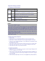
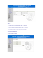
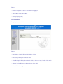
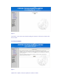
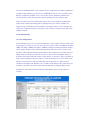
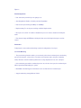
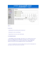
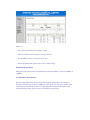
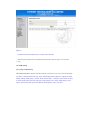
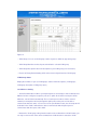
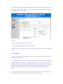
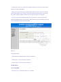
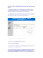
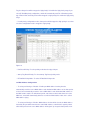
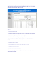
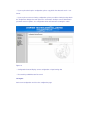
STE2908/2016/2024 User’s Guide
TABLE OF CONTENTS
Chapter One Product Brief Introduction
1.1 Features
1.2 Unpacking
Chapter Two Hardware Installation
2.1 Introduction of Panels
2.2 Environment Required
2.3 Hardware Installation
Chapter Three Configuration Guide
3.1 Fast Log In ························································· 7
3.2 Administrator ······················································ 8
3.2.1 Authentication Configuration ······························ 8
3.2.2 System IP Configuration ······································ 9
3.2.3 System Status ···················································· 9
3.2.4 Load Default Setting ········································ 10
3.2.5 Firmware Update ············································· 11
3.3 Port Management ··············································· 11
3.3.1 Port Configuration ············································· 11
3.3.2 Port Mirroring ··················································· 12
3.3.3 Bandwidth Control ············································· 13
3.3.4 Broadcast Storm Control ·································· 14
3.4 VLAN Configuration·············································· 15
3.4.1 Group VLAN Setting ·········································· 15
3.4.2 Multi to 1 Setting················································ 16
3.5 Trunk Setting ························································ 17
3.6 QoS Setting···························································· 18
3.6.1 Priority Mode ······················································· 18
3.6.2 Class of Service Configuration ···························· 19
3.7 MAC Address Configuration ··································· 20
3.8 Configuration Backup/Recovery ····························· 21
3.9 Logout ···································································· 22
Chapter One Product Brief Introduction
Thanks for purchasing STES2908/2016/2024 Web-Smart Ethernet Switch.
STES2908/2016/2024 is auto-negotiation web-smart switch with auto-negotiation
function. It supports port mirroring, port bandwidth control; You are able to have
real-time monitor on the connectivity status of each port; Supports 8/16/24 groups of
port VLAN and 2 groups of Trunk Configuration, supports QoS, MAC address
Filtering, Broadcast Storm control etc, equipped with individuation operating interface.
It is a high quality low price product especially suitable for Net-bar, SMB (Small and
Medium-size Business), and Smart residential area. Configuration of
STES2908/2016/2024 is simple, enables you to plug and finish the configuration
easily.
1.1 Features
Fully Compliant with IEEE802.3, IEEE802.3u, IEEE802.3x, 8/16/24 10/100Mbps
Auto-Negotiation RJ45 ports, Auto MDI/MDI-X
Basic setting function of each port: 10/100Mbps Auto-Negotiation mode setting,
Full/Half duplex mode setting, 802.3x back pressure flow control setting, port
status indicating
Port Mirroring: To monitor more than one port at the same time, supports port
monitoring receiving, port monitoring sending and port monitoring of receiving
and sending modes, supports monitoring across different VLANs
Port Bandwidth Control: support 16 different levels of port bandwidth control
VLAN: supports port-based VLAN to divide different VLAN groups
Port Trunking: Supports Port Trunking of 2 groups, 2/4 ports per group, support
fault tolerant and hot backup of the cascade connection pipeline
Priority setting: Support 3 types of Priority Queues control, realize simple QoS
application, to prioritize mission-critical data such as voice or video packets
MAC Address Filtering: MAC address learning control, filtering of fixed MAC
address
Broadcast storm control: broadcast storm configuration
Backup: Support the backup and recovery of the configuration of the switch
Firmware upgrade: Support firmware upgrade via TFTP
Easy-to-use operation guide: offer simplified and simple description of function,
operating guide, help user to fast plug and play
Auto-Negotiation on each port senses the link speed of a network device
(either10, 100,1000 Mbps) and intelligently adjusts for compatibility and optimal
performance
Internal high frequency power switching, ensure stable and reliable operating
Standard 19-inch rack-mountable steel case, 1U height
1.2 Unpacking
Please unpack product and you would find the following items inside:
1. One unit of STES2908/2016/2024 Ethernet Switch
2. One Power Line
3. One copy of User’s Manual
4. One copy of Warranty Card
Chapter Two Hardware Installation
2.1 Introduction of LED Indicators
Indicator
POWER
LINK/ACT
Introduction
ON
Power on
OFF
Power Off, please check power line and power interface
ON
Other device is connected to the port in normal condition
Blinking The port is transferring or receiving data
SYS
Blinking
ON
Switch is restoring to factory default setting or is restored to
factory default setting
System is started in normal condition
Note:
How to use the “RESET” button?
If you want to restore to factory default setting, please press the RESET button
when power is off, and then turn on the power, the system LED will shrink for
several times, then please release the RESET button, after around 5 seconds,
the system LED will shrink for several times again, this means that reset has
been finished. Please turn power off and then restart, then switch will be
restored to factory default setting.
Cautions: Unless you require to delete the current configuration, please don’t
press RESET casually.
2.2 Working Environment Required
Ethernet LAN
Connect the port of STES2908/2016/2024 to LAN with twisted pair cable
Web Browser should be Microsoft IE 4.0 or Netscape Navigator 4.0 or above
Operating system supporting Windows, Linux, NetWare etc, and network should
be compliant with TCP/IP
Please put the switch with base down and don’t put heavy items on top of switch
Please put switch away from heat, ensure enough air flowing near the switch
Please don’t put switch in dirty or wet environment
2.3 Hardware Installation
Switch to PC: PC is connectable to any port of switch through Catalogue 3/4/5
UTP/STP straight or cross over cable
Switch to Hub (Through Uplink port): MDI-II Uplink port of Hub (10, 100BASE-TX)
is connectable to any port of switch through Catalogue 3/4/5 UTP/STP straight or
cross over cable
Switch to Hub (no Uplink port): If the hub is not equipped with uplink port (MDI-II),
you are still able to connect any port of the hub to any port of the switch through
Catalogue 3/4/5 UTP/STP straight or cross over cable
Switch to Switch: You are able to connect any port of two switches through
Catalogue 3/4/5 UTP/STP straight or cross over cable
Note:
Please make sure that there is only one uplink pipeline between switch and switch, or
between switch and hub, otherwise multi pipeline will form loops, this may cause the
whole network to broke down. (Port Trunking is an exception)
Chapter Three Configuration Guide
3.1 Fast Login
Notice: You must set IP Address manually for the management PC, because there is
not built-in DHCP server in STES2908/2016/2024. You can login and configure the
switch after setting the IP Address. The default parameters of the switch are as
follows:
Parameter
Default Value
Default IP Address
192.168.0.1
Default User’s Name admin
Default Password
admin
Figure 1
You can fast log in to the configuration Interface of the switch through the following
steps:
a. Connect the switch to NIC port of the computer
b. Turn on the power of the switch
c. Make sure that the IP Address of the computer is at 192.168.0.x (where x is a
number between 2 and 254)
d. Open the Web browser, enter IP Address http://192.168.0.1 into the address
location
e. Input user name and password in the dialog page (default user name and password
are “admin”), press “Enter” button and you will login to the configuration Interface of
the switch as the Figure as follows:
Figure 2
On the menu which is on the left hand side of the page, there are totally 8 items:
“ Administrator ”, “ Port Management ”, “ VLAN Setting ”, “ Trunk Setting ”, “ QoS Setting ”,
“ MAC Address Configuration ”.,” Configuration Backup/Recovery ” and “ Logout ”. Single click
on a certain button and you will have the related function configured. We will give detailed
introduction to the setting step by step in the following chapters.
3.2 Administrator
3.2.1 Authentication Configuration
To set the log in name and password of the switch
Figure 3
• User Name: Input user name for logging in (Max. 15 characters)
• New Password: Input password for logging in (Max. 15 characters)
• Password Confirmation: Input password again for confirmation
3.2.2 System IP Configuration
To set the IP address of switch
Figure 4
• IP Address: Input the IP address of the switch for logging in
• Sub-Net Mask: Input Sub-Net Mast
• Gateway: Input gateway
3.2.3 System Status
To display the status of switch
Figure 5
• MAC Address of Switch: Display MAC address of switch
• Port Quantity: Display port number of switch
• Switch Description: Display description of switch, to define the usage, location of the switch.
• Software Version: Display the software Version of the switch
3.2.4 Load Default Setting
Figure 6
Load : Click “ Load” and restore to default setting, this function is similar to the function of the
“Reset” button.
3.2.5 Firmware Update
Figure 7
Update: Click “Update” and start to update the software of switch
You must install DHCP+TFTP server software on your computer before software updating, it is
strongly recommended that you should use haneWIN DHCP Server Ver2.1 or higher version.
After the configuration of DHCP server, click “Update” button, updating of software takes
around 2 minutes; switch will restart after software updating, and you should re-log in.
Note: You could also visit our website www.stephen-tel.e.com to obtain the updating data
packet and the detailed operating guide for updating. Please be careful in updating, it is
suggest that you should disconnect the network connectivity except the connectivity with the
computer for updating, and please avoid power off in accident or computer broke down of the
updating computer.
3.3 Port Management
3.3.1 Port Configuration
In port management you can set: port Auto-Negotiation, speed, duplex, and flow control mode
respectively for each port. So you can choose the port to work at status of: 10Mbps half duplex,
10Mbps full duplex, 100Mbps half duplex, 100Mbps full duplex and Auto-Negotiation, totally 5
modes. (Notice: Default mode is Auto-Negotiation Mode). When the switch is started, each
port of the switch will automatically negotiate with the connected devices and it will choose an
optimal mode to maximize performance of all devices. For non-Auto-Negotiation modes, it
should be matched and adjusted to status of other devices, or the others devices should be at
status of Auto-negotiation, otherwise, failure of communication will occur. Flow control means
that two connected devices will control data flow and avoid packet loss. 802.3x mode is
suitable for full-duplex mode. Backpressure is suitable for half-duplex mode. If two modes are
all started, switch will choose flow control mode automatically according to duplex modes.
Configuration of port management will affect port bandwidth control, port mirroring and
Trunking.
Figure 8
Port Configuration
• Port: Select the port which you are going to set.
• Auto-Negotiation: Enable or disable port Auto-Negotiation
• Rate: Set the port working at 10Mbps or 1000Mbps
• Duplex Setting: To set the ports working at full/half duplex modes.
• Back pressure control: To enable or disable back pressure control, suitable for half duplex
mode.
• Flow Control: Support IEEE802.3x full duplex flow control, half duplex backpressure flow
control
Port Status
To display the current and actual working mode and configuration of each port
3.3.2 Port Mirroring
• The port mirroring function enables you to transfer packet from monitored port to monitoring
port (received packet, sent packet or sent and received packet mode set by the monitoring
mode). Meet the network monitoring demand of security department in net café, enterprise.
• If the monitoring port and the monitored port are set to be the same port, the monitored port
will be ignored automatically by the system.
• Bandwidth of monitoring port should be the same or wider than the monitored port
• Support monitoring among different VLANs
Figure 9
Port Mirroring:
• Monitoring Mode: Set monitoring mode aimed at packet
• Monitoring Port: Select a monitoring port
• Monitored Port: Select one or more monitored ports
3.3.3 Bandwidth Control
• Port Bandwidth Control: port bandwidth control enables you to control the transmission rate
of each port, including upstream and downstream, and stop the user of a certain port from
using too much bandwidth. And user of other ports will have more stable bandwidth. This
function can be used in net café or broadband connection to smart residential area.
• If the rate set is higher than the actual connectivity rate of the port, the value displayed is the
value that you set, but not the value of the actual value.
Figure 10
• Port: Select the port that you are going to control
• Transmission Rate: Set the transmission rate of the port
• Receiving Rate: Set the receiving rate of the port
• Restore to Default Setting: Click and restore to default setting
Bandwidth Control Status
Display the Transmission Rate, Receiving Rate and Connecting Rate of each port (10Mbps or
100Mbps)
3.3.4 Broadcast Storm Control
Broadcast Storm Max Value refers to the Broadcast Storm Limited Value, for example, if
Broadcast storm packets received at 100Mbps in 10ms reach 127 (or the pre-set Max Value),
switch will detect that Broadcast Storm is happening. And it will start the Broadcast Storm
Control function and give up the unnecessary broadcast storm packets.
Figure 11
• Control Function Selecting: Choose to Start control function
• Broadcast Storm Max Value: the Max Broadcast Storm Value that you can set (From
1~127)
3.4 VLAN Setting
3.4.1 Group VLAN Setting
STES2908/2016/2024 supports Port-Based VLAN, only the port set in the same VLAN group
are able to communication with each other, and VALN group description is supported. Under
default setting, VLAN group 1 contains all the 8/16/24 ports, so all ports of the switch are able
to communicate with each other; One port can belong to one or more VLAN groups, and is
able to communicate with ports from different VLAN groups at the same time .
Figure 12
• VLAN Group: You can set VLAN group number. System is default to support 24 groups.
• VLAN Group Members: Select the port and add to the selected VLAN group
• VLAN Group Description: Give brief description to your VLAN group (in 16 characters)
• Restore to Factory Default Setting: Click and restore to original function of VLAN group
VLAN Group Status
Display the members of your set VLAN groups and the VLAN descriptions. (VLAN groups,
VLAN group description, VLAN group status)
3.4.2 Multi to 1 Setting
• Smart Residential Area VLAN is specially designed for connectivity in smart residential area.
With the function configured, except the port set as uplink, all the other 7/15/23 ports will be
divided as 7/15/23 VLANs automatically. These 7/15/23 port are able to visit the external
network (for example the Internet) through the Uplink port, but the ports are not able to
communicate with each other. You can also use the port disable function, the selected port will
be disable in the VLAN, it will neither be able to communicate with the Uplink port nor
communicate with other ports of the switch.
• Between the VLAN group setting function and the smart residential area VLAN function, you
can only set one function. If the smart residential area VLAN function is started, the VLAN
group function will be replaced automatically by the smart residential area VLAN function; and
if the VLAN group function is started, the smart residential area function will be replaced by the
VLAN group function automatically.
Figure 13
• Uplink Port: Select one port as the Uplink port
• Current Setting: Display the currently set Uplink port
• Disable Ports: Select and disable the port, it will not be able to join the smart residential area
VLAN.
3.5 Trunk Setting
• Trunk is usually called port aggregation, mainly used for hot backup, fault tolerant in uplink
pipeline between switches.
• 4 Trunk Arithmetic s: Arithmetic s based on source port ID value of port which is transmitting
the packet; Arithmetic s based on source MAC address value of the port which is transmitting
the packet; Arithmetic s based on destination MAC address value of the port which is receiving
packet; Arithmetic s based on the value computed according to the “And” arithmetic s result
between the source MAC address of the packet and the destination MAC address of the
packet.
• Each port can be set to have 2 or 4 ports, port set to trunk group can be used only in trunk
group, no matter whether the port is being used in the trunk group or not.
• Trunk group can not cross VLAN, all Trunk group members must be in the same VLAN,
otherwise Trunk function will fail.
• When you use the trunk group for uplink between switches, please make sure that ports
from another switch are also set in the same trunk group in that switch. That is to say, you
must uplink multi ports between switches in the way of trunk group to trunk group.
• Please do not connect two trunk groups in the same switches, or do not connect two
switches through two groups of trunk groups. All these will cause loop, broadcast storm may
occur and the whole network may broke down.
Figure 14
Trunk group setting:
• Trunk Arithmetic Selecting: Please select one arithmetic
• Trunk Group 1: select trunk group 1 members
• Trunk Group 2: select trunk group 2 members
3.6 QoS Setting
3.6.1 Priority Mode
• If the value is “0”, system will treat it as “8” as default
• In First in First out mode, switch will ignore the priority of data packets, the packets
transferred to the switch first will be transmitted first. This mode is not recommended if Priority
mode is set.
• In absolutely Priority mode, switch will forward data packets according to priority level
strictly. Only after the data packets in the queue with high priority level are forwarded, the
switch will forward the data packets in the queues with lower priority level.
• In weight arithmetic control mode, according to the high and low weight value computing
rate, switch forwards in turn data packets of high priority and low priority and avoids the data
packet with low priority staying in switch for too long and being given up.
Figure 15
• Control Mode: To select the Priority control mode of switch
• Priority Value: To select the priority value of High and Low
3.6.2 Class of Service Configuration
• Through configuration of priority mode and priority control operation, you are able to realize
simple QoS function. STES2908/2016/2024 support data packet mapping of high and low
priority, 3 types of priority configuration mode.
• If you select port based priority and select a certain physical port as high priority, then data
packets entering this port will be mapped as high priority; If you select 802.1p Tag-based
priority, switch will automatically read the priority tags in the data packets with 802.1p VLAN
Tag, the data packet will be mapped as high priority if it is within the high priority range; If you
select IP TOS/DS priority configuration, switch will automatically read TC of IPv6 data packet/
tag of TOS in IPv4, the data packet will be mapped as high priority if it is within the high priority
range.
• In multi priority configuration modes, data packet will be mapped as high priority in case that
one of the configuration mode is mapped as high priority.
Figure 16
• Port Based Priority: To select priority mode based on physical port
• 802.1p Tag Based Priority: To select 802.1p Tag Based priority mode
• IP TOS/DS Priority Mode: To select IP TOS/DS Priority mode
3.7 MAC Address Configuration
• To select port filtering as “Disable” : Enable port MAC address learning function,
automatically reads the source MAC address and destination MAC address of the data packet
received, and automatically record the source MAC address and destination MAC address in
the MAC address table; If in defined time period, switch doesn'
t detect data flow from source
MAC host, switch will automatically delete its record in the MAC address table, this is called
MAC address aging.
• To select port filtering as “Enable”: MAC address function will be closed, the MAC address
learned by the port will be transferred as static MAC address, and will not be aged by switch,
all the data packets from source MAC address will be given up except the data packets from
the static MAC address; If you input the MAC address going to be filtered in the MAC Address
Filter dialogue box, all the data packets with these MAC address will be given up (including the
data packets from the static MAC address) by switch.
Figure 17
• Port:: The port you are setting
• MAC Address Filtered: Input the MAC address that you are going to filter, and configuration
will go into effect when you select “ Enable ” in filter configuration.
• Port selection: Select the port that you are going to configure
• Filter: Select “Disable” or “ Enable ” Filtering regulation, this is similar to MAC address
learning
• MAC Address Filtering Function
• Display filtering status of the port, the status of MAC address learning
• Configuration Backup/Recovery
To Backup or Restore configuration of switch
• Please do not change or submit the configuration casually, otherwise this may cause the
switch to fail to work normally.
• If you require to backup the configuration, please copy all the hex data and save in “*.txt”
format.
• If you require to restore to forming configuration, please past all the forming backup data in
the configuration dialogue box and replace the current data. And input correct administrator
password and click “Update”, the configuration will be affected after restarting the switch.
Figure 18
• Configuration Content: Display current configuration or input forming data
• Password: Input Administrator Password
3.9 Logout
Quit current configuration and close the configuration page.