1
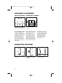
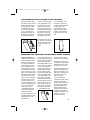
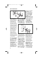
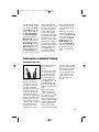
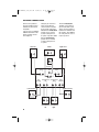
SCS-SAT500,300,200 OM
4/25/07
11:39 AM
Page 3
THANK YOU FOR CHOOSING JBL
For more than 60 years, JBL
has been involved in every
aspect of music and film
recording and reproduction,
from live performances to
the recordings you play in
your home, car or office.
ment that you expected –
and that when you think
about purchasing additional
audio equipment for your
home, car or office, you will
once again choose JBL.
We’re confident that the JBL
speaker you have chosen will
provide every note of enjoy-
®
Please take a moment to
register your product on our
Web site at www.jbl.com.
It enables us to keep you
posted on our latest advancements, and helps us to better
understand our customers
and build products that meet
their needs and expectations.
JBL, Inc.
INCLUDED
One SCS SAT500, one SCS SAT300
or one SCS SAT200 with wall-mount
bracket, shelf stand and floor stand
adapter.
One 40' (12m) speaker cable.
In addition, there are two hardware
bags included. Hardware Bag A
contains the metal tightening bar and
screw for the shelf stand. Hardware
Bag B contains screws for the floor
stand adapter and parts for the
wall-mount bracket.
®
SURROUND CINEMA
SPEAKERS
SCS SAT500
SCS SAT300
SCS SAT200
OWNER’S GUIDE
SCS-SAT500,300,200 OM
4/25/07
11:39 AM
Page 2
SPECIFICATIONS
SCS SAT500, SCS SAT300
SCS SAT200
Maximum Recommended Amplifier Power
100 Watts
Power Handling (Continuous/Peak)
50W/200W
Nominal Impedance 8 Ohms
Sensitivity 88dB @ 1 Watt/1 meter
Frequency Response 100Hz – 20kHz (–6dB)
Tweeter
1/2" (13mm) Titanium-laminate dome,
video-shielded
Midrange
Dual 3" (75mm) drivers, video-shielded
Dimensions (H x W x D) (not including shelf stand)
11-1/2" x 4" x 3-1/2" (292mm x 102mm x 89mm)
Weight 3 lb (1.4kg)
Maximum Recommended Amplifier Power
100 Watts
Power Handling (Continuous/Peak)
50W/160W
Nominal Impedance 8 Ohms
Sensitivity 86dB @ 1 Watt/1 meter
Frequency Response 100Hz – 20kHz (–6dB)
Tweeter
1/2" (13mm) Titanium-laminate dome,
video-shielded
Midrange
3" (75mm) Driver, video-shielded
Dimensions (H x W x D) (not including shelf stand)
7-1/4" x 4" x 3-1/2" (184mm x 102mm x 89mm)
Weight 1.75 lb (0.8kg)
Declaration of Conformity
We, Harman Consumer Group, Inc.
2, route de Tours
72500 Château du Loir
France
declare in own responsibility that the products described in this
owner’s manual are in compliance with technical standards:
EN 61000-6-3:2001
EN 61000-6-1:2001
Features, specifications and appearance are subject to
change without notice.
Laurent Rault
Harman Consumer Group, Inc.
Château du Loir, France 4/07
Dolby is a registered trademark of Dolby Laboratories.
DTS is a registered trademark of DTS, Inc.
OWNER’S GUIDE
PRODUCT
PRO SOUND
COMES HOME™
LINE:
SURROUND CINEMA
SPEAKERS
MODELS: SCS SAT500,
SCS SAT300,
SCS SAT200
DESIGN GOAL: Bring the thrill of live performance
and movie sound to the home environment by calling on JBL’s
professional engineering leadership.
SATELLITE TYPE:
Titanium-laminate-dome tweeter,
sealed enclosure
PROFESSIONAL REFERENCE:
Loudspeaker Series
Cinema
Harman Consumer Group, Inc.
250 Crossways Park Drive, Woodbury, NY 11797
8500 Balboa Boulevard, Northridge, CA 91329
516.255.4JBL (4525) (USA only)
www.jbl.com
© 2007 Harman International Industries, Incorporated.
All rights reserved.
JBL is a trademark of Harman International Industries,
Incorporated, registered in the United States and/or
other countries. Pro Sound Comes Home is a trademark
of Harman International Industries, Incorporated.
Part No. 406-000-05723-E
SCS-SAT500,300,200 OM
4/25/07
11:39 AM
Page 4
SPEAKER PLACEMENT
FRONT SPEAKERS
SURROUND SPEAKERS
†
1.5 – 1.8m
5 – 6 ft
†
Placement for back speakers.
† Placement
for surround back speaker in a 6.1 system.
The SCSSAT500, SCSSAT300
and the SCSSAT200 loudspeakers are designed to be
used either singly or in a pair
to upgrade a 5.1-channel
home theater system to a
6.1- or 7.1-channel system,
when connected to a compatible receiver or processor
and amplifier.
The rear wall is the required
placement for the back surround speakers in a 7.1channel system. The back
surround speaker in a 6.1channel system should be
placed on the wall behind
the listening position, facing
the center channel speaker.
It is neither necessary nor
desirable to tilt the surround
speakers to aim them down
toward the listening area.
They should be aimed
straight ahead to produce
the proper effect.
MOUNTING OPTIONS
On a shelf.
2
On the wall. A wall bracket
is included.
On an optional stand.
SCS-SAT500,300,200 OM
4/25/07
11:39 AM
Page 5
ATTACHING THE SHELF STAND TO THE SPEAKER
Prepare the speaker wire as
described on Page 5. Thread
the two conductors through
the two holes in the stand
bracket. Make sure to preserve the proper polarity
(+ and – connections) by
threading the positive conductor through the hole on
the left, and the negative
+
–
conductor through the hole
on the right looking at the
stand from the front. Push
down on the red speaker
terminal and insert the bare
end of the positive wire into
the hole under the red cap.
Release the cap, and tug
gently on the wire to make
sure that the connection
is snug. Follow the same
procedure to connect the
negative wire to its terminal.
Use the larger screw
(Hardware Bag A) in the
upper screw hole, and the
smaller screw (Hardware
Bag A) in the lower screw
hole.
Gently pull the slack out of
the wire and screw the shelf
stand onto the back of the
speaker in two places, as
shown.
MOUNTING THE SATELLITES ON OPTIONAL FLOOR STANDS
Important Safety Note: The
supplied floor stand adapters
facilitate installation with a
variety of general-purpose
floor stands available from
many manufacturers. Since
different stands will have
different weight capacities
and stability characteristics,
it is the customer’s responsibility to check with the stand
manufacturer or dealer to determine whether that specific
stand is capable of handling
the weight and proportions
of these loudspeakers in a
safe and stable manner. JBL
disclaims any liability for the
selection of suitable floor
stands and/or correct
compatibility between the
selected stand and these
satellite loudspeakers.
The floor stand adapters are
compatible with floor stands
equipped with a 1/4"-20
threaded insert.
Prepare the speaker wire as
described on Page 5. Thread
the two conductors through
the two holes in the floor
stand adapter. Make sure to
preserve the proper polarity
(+ and – connections) by
threading the positive conductor through the hole on
the left, and the negative
conductor through the hole
on the right (looking at the
front of the adapter). Push
down on the red speaker
terminal and insert the bare
end of the positive wire into
the hole under the red cap.
Release the cap, and tug
gently on the wire to make
sure that the connection
is snug. Follow the same
+
–
procedure to connect the
negative wire to its terminal.
Gently pull the slack out of
the wire and screw the adapter
onto the back of the speaker
in two places, as shown.
The floor stand adapter screws
may be found in Hardware
Bag B. Use the larger screw
in the upper screw hole, and
the smaller screw in the
lower screw hole.
Screw the floor stand
adapter into the floor stand’s
threaded insert until the
speaker is firmly attached to
the stand. Back off slightly
from the fully tightened
position until the speaker
is oriented as desired, then
rotate the thumbwheel at
the bottom of the floor stand
adapter to secure the
speaker to the stand.
3
SCS-SAT500,300,200 OM
4/25/07
11:39 AM
Page 6
WALL-MOUNTING
and the back of the Satellite
Speaker ¶, using large
needle-nose pliers until it is
firmly seated against the back
of the Satellite Speaker ¶
and has locked the Ball and
Shaft £ and the Satellite
Speaker ¶ together.
NOTE: Once the Metal Nut ¡
is fully tightened, it may embed
some marks on the back of the
Satellite Speaker ¶. However,
these marks will be covered
by the Metal Nut ¡.
Step 6: Mount the Attachment Plate ¢ into a wood
stud on the wall, using four
4
3
2
1
8
5
Important Safety Note: The
customer is solely responsible for proper selection of
mounting hardware not
included with the speaker,
and for proper assembly
and installation of the wallmount bracket, including but
not limited to the selection of
appropriate weight-bearing
supports and proper use of
the bracket. JBL disclaims
any liability for the selection
of mounting hardware
and/or bracket installation.
Be sure to follow these
bracket assembly and
installation instructions
carefully. If you have any
questions or doubts about
your ability to correctly wallmount the speakers, consult
your authorized JBL dealer
or custom installer.
Step 1: Unscrew and remove
the large Molded Nut ™. If
necessary, use the supplied
Metal Bar ∞ as a lever by
inserting it into one of the
holes in the outer edge of
the Molded Nut ™.
Step 2: Firmly grasp the Ball
and Shaft £ and pull it
straight out of the Attachment Plate ¢. Avoid leaning
it to the side for leverage, as
this may break off a tab.
4
Step 3: Slide the Molded Nut
™ onto the Ball and Shaft
£ with the threaded opening facing the ball. Thread
the Metal Nut ¡ all the way
onto the Ball and Shaft £,
7
6
1
2
3
4
5
8
with the star washer side
away from the ball. Refer to
the exploded drawing for the
proper orientation of these
parts.
Step 4: Screw the Ball and
Shaft £ into the Threaded
Insert § on the back of the
Satellite Speaker ¶ until it
is fully seated in the Threaded
Insert §, but do not tighten,
as you might dislodge the
Threaded Insert §. Such
damage would not be covered under the warranty.
Step 5: Tighten the Metal Nut
¡ with the star washer side
between the Metal Nut ¡
#10 panhead wood screws
• at least one inch long
(not supplied). Make sure
that all four screws are
driven into the stud and not
into drywall. If the bracket
needs to be mounted in
drywall, the customer is
responsible for selecting
and using appropriate wall
anchors and screws.
IMPORTANT NOTE: The Metal
Nut ¡ must be fully tightened against the Satellite
Speaker ¶ as described in
Step 5 before beginning Step
7, in order to avoid damage
to the Threaded Insert §.
SCS-SAT500,300,200 OM
4/25/07
Such damage would not be
covered under the warranty.
Step 7: Holding the Satellite
Speaker ¶ with both hands,
reinsert the ball portion of
the Ball and Shaft £ into
the Attachment Plate ¢.
Step 8: Hand-tighten the
Molded Nut ™ while positioning the speaker for the
desired orientation. If the
Molded Nut ™ is difficult to
tighten by hand, insert the
Metal Bar ∞ into one of the
holes in the outer edge of
the Molded Nut ™ and use
the bar as a lever. Be careful
11:39 AM
Page 7
not to cross-thread. The
swiveling ball enables you to
aim the speaker to one side
or the other, or to tilt it up
or down. Although stereo
imaging may be improved
by aiming the front speakers
toward the listening position,
especially for music selections, the surround speakers
are intended to provide a diffuse, ambient sound that is
best achieved by aiming the
speakers straight out from
the wall. Aiming the surround speakers toward
the listening position may
ruin the intended effect by
calling too much attention
to the information in those
channels.
Step 9: Once the speaker’s
orientation has been finalized, insert the Metal Bar ∞
into one of the holes in the
outer edge of the Molded
Nut ™ and tighten the
Molded Nut ™ securely.
Keep the Metal Bar ∞ in a
safe place, in the event that
you decide to adjust the
speaker’s orientation in the
future.
SPEAKER CONNECTIONS
CONNECTION TIPS
denote the (+) terminal and
black to denote the (–)
terminal.
Separate and strip the
ends of the speaker wire
as shown. The wires supplied with the system may
already be stripped and
tinned for easy insertion into
the speaker terminals. You
may need to separate the
two conductors further in
order to thread them through
the shelf stand or floor stand
adapter. Speakers and electronics terminals have corresponding (+) and (–) terminals.
Most manufacturers of
speakers and electronics,
including JBL, use red to
The (+) lead of the speaker
wire is noted with a stripe.
It is important to connect
both speakers identically:
(+) on the loudspeaker to
(+) on the amplifier and (–)
on the loudspeaker to (–) on
the amplifier. Wiring “out of
phase” results in thin sound,
weak bass and a poor stereo
image.
and center speaker terminals,
press the red or black plastic
cap for the desired terminal,
insert the bare end of the
wire into the hole below the
cap and release the cap.
Gently tug on the wire to
make sure that it is fully
inserted.
With the advent of multichannel surround sound
systems, connecting all of
the speakers in your system
with the correct polarity
remains equally important in
order to preserve the proper
ambience and directionality
of the program material.
To connect the supplied
speaker wires to the satellite
5
SCS-SAT500,300,200 OM
4/25/07
11:39 AM
Page 8
SYSTEM CONNECTION
Connect each speaker to
the corresponding speaker
terminals on your receiver
or amplifier.
Configure your receiver or
processor to reflect the
correct number of speakers
in your system. If you have
added one SCS SAT500/300/200
speaker to a 5.1-channel
system, reconfigure it as a
6.1 system. If you have added
two SCS SAT500/300/200
speakers to a 5.1-channel
system, reconfigure it as a
7.1 system.
If you are using a subwoofer,
follow the directions in that
owner’s guide to connect
and configure it.
Left Front
–
The SCS SAT500/300/200
should be set to “Small.” If
your receiver allows you to
set the crossover frequency
between the subwoofer and
the speakers, select 100Hz or
the setting that is the closest
frequency below it.
Right Front
Center
–
+
+
–
+
Subwoofer
LFE In
Receiver
Subwoofer
Out
Left
Front
–
Right
Front
+
–
–
+
+
Center
Left
Surround
–
+
Surround Back
Left
–
+
Surround Back
Right
Right
Surround
–
+
+
–
–
+
–
+
Surround Back Surround Back
Left
Right
6
+
Right Surround
Left Surround
–
–
+
SCS-SAT500,300,200 OM
4/25/07
11:39 AM
Page 9
TROUBLESHOOTING
If there is no sound from any
of the speakers:
• Check that receiver/amplifier
is on and a source is playing.
• Check all wires and connections between receiver/
amplifier and speakers.
Make sure all wires are
connected. Make sure
none of the speaker wires
are frayed, cut or punctured,
or touching each other.
• Review proper operation of
your receiver/amplifier.
If there is no sound coming
from one speaker:
• Check the “Balance” control
on your receiver/amplifier.
• Check all wires and connections between receiver/
amplifier and speakers.
Make sure all wires are
connected. Make sure
none of the speaker wires
are frayed, cut or punctured,
or touching each other.
• In Dolby® Digital or DTS®
modes, make sure that the
receiver/processor is configured so that the speaker
in question is enabled.
• Turn off all electronics
and switch the speaker in
question with one of the
other speakers that is
working correctly. Turn
everything back on, and
determine whether the
problem has followed the
speaker, or has remained
in the same channel. If the
problem is in the same
channel, the source of the
problem is most likely with
your receiver or amplifier,
and you should consult the
owner’s manual for that
product for further information. If the problem has
followed the speaker, consult your dealer for further
assistance or, if that is not
possible, visit www.jbl.com.
If the system plays at low
volumes but shuts off as
volume is increased:
• Check all wires and connections between receiver/
amplifier and speakers.
Make sure all wires are
connected. Make sure
none of the speaker wires
are frayed, cut or punctured,
or touching each other.
• If more than one pair of
main speakers is being
used, check the minimum
impedance requirements
of your receiver/amplifier.
If there is low (or no) bass
output:
• Make sure the connections
to the left and right “Speaker
Inputs” have the correct
polarity (+ and –).
• If your system includes a
subwoofer, check its operation and the configuration
of your receiver or processor. If your system has no
subwoofer, consider adding
a powered subwoofer.
If there is no sound from
the surround speakers:
• Check all wires and connections between receiver/
amplifier and speakers.
Make sure all wires are
connected. Make sure
none of the speaker wires
are frayed, cut or punctured,
or touching each other.
• Review proper operation of
your receiver/amplifier and
its surround sound features.
• Make sure the movie or
TV show you are watching
is recorded in a surround
sound mode. If it is not,
check to see whether your
receiver/amplifier has other
surround modes you may use.
• In Dolby Digital or DTS
modes, make sure your
receiver/processor is configured so that the surround
speakers are enabled. When
five satellites are in use,
remember to configure your
receiver or processor for
6.1-channel operation,
and when six satellites
are in use, configure your
receiver or processor for
7.1-channel operation.
• Review the operation of
your DVD player and the
jacket of your DVD to make
sure that the DVD features
the desired Dolby Digital
or DTS mode, and that you
have properly selected that
mode using both the DVD
player’s menu and the DVD
disc’s menu.
7


![PS manual[P].qXp2](http://vs1.manualzilla.com/store/data/005858764_1-0e0b40902f5a565498b3e3a041c7e706-150x150.png)