1
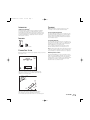
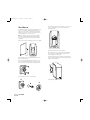
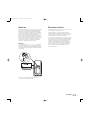
TSS-SAT500 OM
11/14/05
4:14 PM
Page 1
TOTAL SPEAKER SOLUTIONS
TSS-SAT500
Owner’s Guide
TSS-SAT500 OM
11/14/05
4:14 PM
Page 2
TSS-SAT500 OWNER’S GUIDE
Table of Contents
2
3
Introduction
3
Included
3
Planning Your System
3
Placement
4
Wall-Mounting
5
Connections
5
Maintenance and Service
7
Specifications
TSS-SAT500
TSS-SAT500 OM
11/14/05
4:14 PM
Page 3
INTRODUCTION
PLACEMENT
Infinity Total Solutions
™
Infinity Total Solutions continues Infinity’s longstanding commitment
to accurate sound reproduction. Our high-quality drivers, precision
dividing networks and rigid, well-braced enclosures combine to deliver
uncompromised performance in any multichannel home theater system.
In addition, the TSS-SAT500 is magnetically shielded for safe placement adjacent to a television.
INCLUDED
NOTE: The TSS-SAT500 can be placed directly on a shelf,
or mounted on a wall using the included wall bracket.
As Left and Right Front Channels
For left and right front channels, place one satellite to the left
and another to the right of the television, as shown in Figure 1.
Since the speakers are magnetically shielded, you can place
them very close to the TV without worrying about the magnetic
field distorting the picture.
As Surround Channels
For left and right surround channels, place one speaker on the
left and another on the right, to the side of or slightly behind the
listening area.The surround speakers should be mounted at a
height of between 5 ft. (1.5m) and 7 ft. (2m).
®
(1) Speaker
In 6- or 7-channel configurations, place the rear channel(s)
behind the listening position, as shown in Figures 1 and 2.
(1) Wall bracket
PLANNING YOUR SYSTEM
NOTE: An Infinity powered subwoofer will add impact and realism
to both music and film soundtracks. Contact your Infinity dealer
for recommendations on subwoofer models for your application.
Before deciding where to best place your speakers, survey your room and
study Figures 1 and 2.
Mounting on Floor Stands
Subwoofer
Left Front
Channel
Center
Channel
Right Front
Channel
An optional TSS-STAND500 floor stand is available, should you
prefer to place your TSS-SAT500 satellites on the floor; see your
dealer or visit www.infinitysystems.com for more information.
In addition, there is a 1/4"-20 insert in each satellite that allows
the satellite to be mounted to many third-party floor stands.
Unscrew the rear foot to reveal the insert.
keyhole on the back of the speaker to the screwhead on the
Couch
Left Rear
Channel
Left
Surround
Channel
Center Rear
Channel
Right Rear
Channel
Right
Surround
Channel
Figure 1.This overhead view shows a typical home theater plan.
Left/right rear channels are for a 7-channel system. Center rear
channel is for a 6-channel system.
Subwoofer
Right Front
Channel
Center
Channel
Right
Surround
Channel
Left Front
Channel
Right Rear
Channel
Left
Surround
Channel
Left Rear
Channel
Center Rear
Channel
Figure 2.This figure shows an alternate layout, which may be
more suitable for some rooms. Left/right rear channels are
for a 7-channel system. Center rear channel is for a 6-channel system.
TSS-SAT500
3
TSS-SAT500 OM
11/14/05
4:14 PM
Page 4
WALL-MOUNTING
The TSS-SAT500 satellite is designed to be mounted on the wall.
There is a wall bracket included.The speaker bracket will
require four 1-1/2" #10 wood screws; each screw should be
fastened to a wall stud. If a wall stud is unavailable, install an
anchor appropriate for a 1-1/2" #10 screw.
Step 5. Screw the ball and shaft assembly (B) to 1/4"-20 insert
on rear of speaker. Back out 1/2 of a turn and tighten nut
against the speaker.
NOTE: The customer is responsible for the correct selection
and use of mounting hardware (available through hardware
stores) that will ensure the proper and safe wall-mounting of
the speakers.
Step 1. Detach shelf stand by removing screw in rear of speaker.
Step 6. Attach speaker wire as shown on page 5.
Step 7. Drop round collar (C) over ball and shaft assembly (B)
that is mounted to the speaker with the finished side of the
collar facing the rear of the speaker.
Step 2. Mark the positions on the wall where you would like to
place the mounting screws.
Step 8. Carefully push the ball straight into the socket mounted
on the wall, angle the speaker as desired and tighten the collar
using the enclosed metal bar.
.
Step 3. Place bracket against the wall and fasten four 1-1/2"
#10 wood screws through the bracket’s screw holes into the
wall. If a wall stud is not available, use an appropriate anchor.
Metal bar
Step 4. Unscrew round collar (C) from bracket (A).
®
A
Figure 3. Bracket on wall.
B
4
TSS-SAT500
C
TSS-SAT500 OM
11/14/05
4:14 PM
Page 5
CONNECTIONS
MAINTENANCE AND SERVICE
After placing the speakers, you are ready to connect your system.
First, turn off all audio-system power. Use high-quality speaker
wire to make your connections. #18-gauge speaker wire with
polarity coding is included. For longer distances, #16-gauge or
heavier wire is recommended.The side of the wire with a ridge
or other coding is usually considered positive polarity (i.e., +).
Also, consult the owner’s manuals that were included with your
amplifier or receiver to confirm connection procedures. Observe
polarities when making speaker connections, as shown in Figure
4. Connect each + terminal on the back of the amplifier or
receiver to the respective + (red) terminal on each speaker.
Connect the – (black) terminals in the same way.
The TSS-SAT500 enclosure may be cleaned using a soft cloth to
remove fingerprints or to wipe off dust.
Important!
Do not reverse polarities (i.e., + to –, or – to +) when making
connections. Doing so will cause poor imaging and diminished
bass response. Be certain that positive and negative wire strands
are completely isolated to avoid short circuits that may damage
your equipment.
All wiring connections should be inspected and cleaned or
remade periodically.The frequency of maintenance depends on
the metals involved in the connections, atmospheric conditions
and other factors, but once per year is the minimum.
If a problem occurs, make sure that all connections are properly
made and clean. If a problem exists in one loudspeaker, reverse
the connection wires to the left and right system. If the problem
remains in the same speaker, then the fault is with the loudspeaker. If the problem appears in the opposite speaker, the
cause is in another component or cable. In the event that your
TSS-SAT500 ever needs service, contact your local Infinity
dealer or distributor, or visit www.infinitysystems.com for a
service center near you.
Press Connector
In and Hold
Insert Bare
End; Release
Connector
–
+
Figure 4. Wiring diagram shows polarity connections
for one channel of a home theater system.
TSS-SAT500
5
TSS-SAT500 OM
11/14/05
NOTES
6
TSS-SAT500
4:14 PM
Page 6
TSS-SAT500 OM
11/14/05
4:14 PM
Page 7
SPECIFICATIONS
TSS-SAT500
Frequency Range:
150Hz – 25,000Hz (±3dB)
Recommended
Amplifier Power Range:
10 – 100 Watts
Sensitivity:
86dB
(2.83V @ 1 meter)
Nominal Impedance:
8Ω
Crossover Frequency:
7,000Hz
Midrange Driver(s):
2-1/2" (64mm) Magnetically shielded
High-Frequency Driver:
3/4" (19mm) Magnetically shielded
Dimensions (H x W x D):
7-11/16" x 3-1/2" x 2-3/4"
(195mm x 89mm x 70mm)
Weight:
1.2 lb (0.5kg)
Infinity continually strives to update and improve existing products, as well as
create new ones.The specifications and construction details in this and related
Infinity publications are therefore subject to change without notice.
Declaration of Conformity
We, Harman Consumer Group International
2, route de Tours
72500 Château du Loir
France
declare in own responsibility that the product described
in this owner’s manual is in compliance with technical
standards:
EN 61000-6-3:2001
EN 61000-6-1:2001
Laurent Rault
Harman Consumer Group International
Château du Loir, France 11/05
TSS-SAT500
7
TSS-SAT500 OM
11/14/05
4:14 PM
Page b
© 2005 Harman International Industries, Incorporated. All rights reserved.
Infinity Systems, 250 Crossways Park Drive, Woodbury, NY 11797 USA www.infinitysystems.com
Infinity and Harman International are trademarks of Harman International Industries, Incorporated, registered in the United States and/or other countries.
Total Solutions is a trademark of Harman International Industries, Incorporated.
Dolby and Pro Logic are registered trademarks of Dolby Laboratories.
DTS is a registered trademark of DTS, Inc.
Part No. 406-000-05350-E 11/05