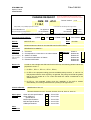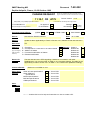
1
ETSI TC SMG#30 Plenary Meeting
Brighton, UK
9th -11th November 1999
Tdoc SMG P-99-566
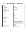
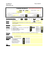
Title:
Phase 2+ (R97) CRs to GSM 11.10-1 (Signalling and RF) for
Approval
Agenda Item:
6.7
Source:
SMG7
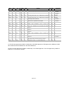
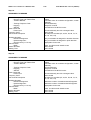
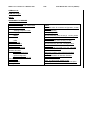
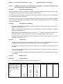
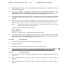
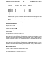
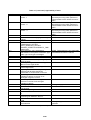
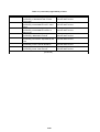
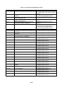
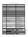
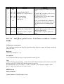
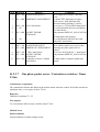
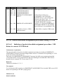
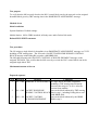
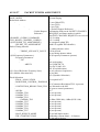
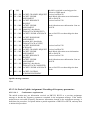
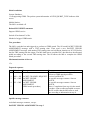
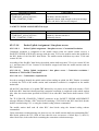
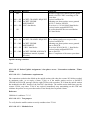
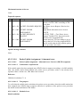
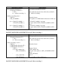
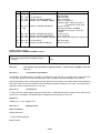
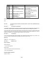
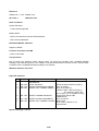
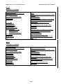
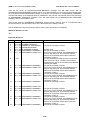
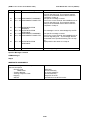
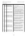
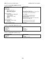
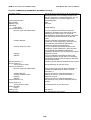
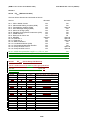
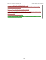
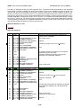
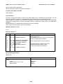
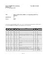
This document contains 31 CRs to GSM 11.10-1, V.6.1.0. These CRs have been agreed by SMG7 and are
put forward to SMG as non-strategic ones for approval without presentation.
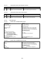
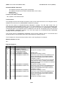
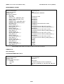
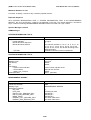
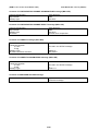
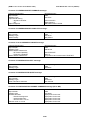
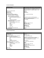
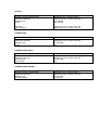
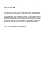
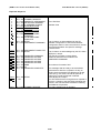
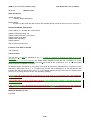
SMG7
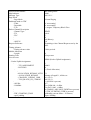
Doc
SPEC
CR
RE PHASE
V
VERS
SUBJECT
CAT NEW_
VERS
WORKITEM
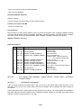
7-99-263
11.10-1
A696
R97
6.1.0
Adding of “Specific Message Contents” for GSM 1800
A
6.2.0
HSCSD
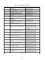
7-99-271
11.10-1
A698
R97
6.1.0
Cell reselection test 20.22.2
F
6.2.0
GPRS
7-99-272
11.10-1
A700
R97
6.1.0
Cell reselection test 20.22.4
F
6.2.0
GPRS
7-99-273
11.10-1
A702
R97
6.1.0
Cell reselection test 20.22.6
F
6.2.0
GPRS
7-99-280
11.10-1
A706
R97
6.1.0
Stop paging in carrier 2 in the EGSM path in test case 20.5
A
6.2.0
DE/SMG-00110P-1
7-99-299
11.10-1
A710
R97
6.1.0
Testing state U6 problem with GSM 11.10-1 test case A
31.2.1.7.2.
6.2.0
DE/SMG-001110P-1
7-99-300
11.10-1
A714
R97
6.1.0
Correction to test case 26.6.3.4, value of information element A
‘BA_used’
6.2.0
DE/SMG-001110P-1
7-99-301
11.10-1
A718
R97
6.1.0
Measurement reporting corrections in test case 26.10.2.1
A
6.2.0
DE/SMG-00110P-1
7-99-312
11.10-1
A720
R97
6.1.0
Correction of applicability clauses
F
6.2.0
GPRS
7-99-313
11.10-1
A722
R97
6.1.0
RR procedures on CCCH related to temporary block flow F
establishment
6.2.0
GPRS
7-99-314
11.10-1
A724
R97
6.1.0
Test of Medium Access Control (MAC) Procedures on PCCCH F
in idle mode
6.2.0
GPRS
7-99-315
11.10-1
A726
R97
6.1.0
Measurement Reports and Cell Change Order Procedures
F
6.2.0
GPRS
7-99-316
11.10-1
A729
R97
6.1.0
HSCSD test 26.13.1.2.1: GSM1800 messages missing; Steps A
28,29 added.
6.2.0
HSCSD
7-99-317
11.10-1
A732
R97
6.1.0
HSCSD section 26.13.1.3: Table 1 corrected
A
6.2.0
HSCSD
7-99-319
11.10-1
A735
R97
6.1.0
HSCSD section 26.13: PICS/PIXIT sections reworked
A
6.2.0
HSCSD
7-99-320
11.10-1
A738
R97
6.1.0
New PICS/PIXIT in GSM 11.10-1 Annex 3
A
6.2.0
HSCSD
7-99-321
11.10-1
A741
R97
6.1.0
Default parameter values on the test SIM card for ASCI testing B
6.2.0
REN/SMG071110QR7-1
Page 1 of 2
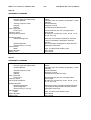
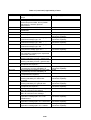
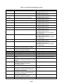
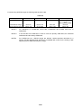
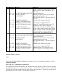
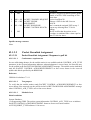
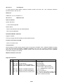
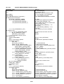
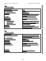
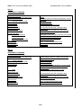
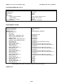
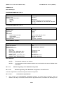
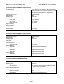
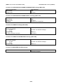
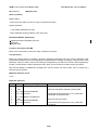
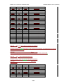
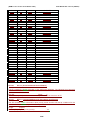
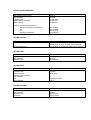
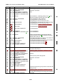
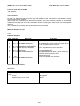
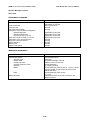
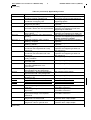
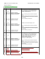
SMG7
Doc
SPEC
CR
RE PHASE
V
VERS
SUBJECT
CAT NEW_
VERS
WORKITEM
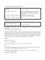
7-99-322
11.10-1
A744
R97
6.1.0
Alignment to the priority levels based on the test SIM card.
A
6.2.0
REN/SMG071110QR7-1
7-99-323
11.10-1
A747
R97
6.1.0
Two editorial changes in the clause 26.14
A
6.2.0
REN/SMG071110QR7-1
7-99-324
11.10-1
A750
R97
6.1.0
Correction of test prose 31.12.2 - eMLPP Service / automatic A
answering point-to-point MT call
6.2.0
REN/SMG071110QR7-1
7-99-326
11.10-1
A753
R97
6.1.0
Correction of test prose 31.12.3 - eMLPP Service / automatic A
answering MT VGCS or VBS call.
6.2.0
REN/SMG071110QR7-1
7-99-327
11.10-1
A756
R97
6.1.0
Correction of test requirements in 31.12.4 and 31.12.5 - A
eMLPP Service / registration and interrogation
6.2.0
REN/SMG071110QR7-1
7-99-346
11.10-1
A759
R97
6.1.0
HSCSD section 26.13.1.3: Authentication procedures missing. A
6.2.0
HSCSD
7-99-351
11.10-1
A763
R97
6.1.0
Update of table “Applicability of Tests” in Section 3.2.2, A
Directed Retry Tests
6.2.0
TEI
7-99-361
11.10-1
A767
R97
6.1.0
Test 27.21.3: Clarification of test procedure and expected A
sequence
6.2.0
TEI
7-99-362
11.10-1
A771
R97
6.1.0
Test 31.6.2.4: Clarification of test procedure and expected A
sequence
6.2.0
TEI
7-99-363
11.10-1
A775
R97
6.1.0
Test 31.6.2.5: Clarification of test procedure and expected A
sequence
6.2.0
TEI
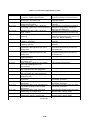
7-99-369
11.10-1
A779
R97
6.1.0
Update of table “Applicability of Tests” in Section 3.2.2, A
deletion of test case 26.12.2.2
6.2.0
TEI
7-99-370
11.10-1
A782
R97
6.1.0
Correction of test prose 31.12.1 - eMLPP Service / priority level A
of MO call
6.2.0
REN/SMG071110QR7-1
7-99-349
11.10-1
A785 (2)
R97
6.1.0
Introduction of GPRS test mode as a means of establishing C
uplink TBF in Power Control test cases (22.3 and 22.4)
6.2.0
GPRS
7-99-255
11.10-1
A788 (1)
R97
6.1.0
Modification of section 11.7 to enhance IMEI security
6.2.0
TEI
A
(1) This CR was approved by SMG7 conditionally to the SMG approval of CRs approved by SMG10 to GSM
02.09, GSM 03.03 and GSM 02.16 in document AP99-101.
(2) This CR was approved by SMG7 conditionally to the SMG approval of the CR approved by SMG2 to
GSM 04.14 in document 2-99-D06.
Page 2 of 2
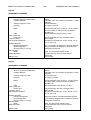
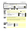
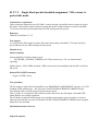
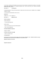
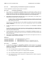
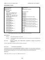
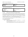
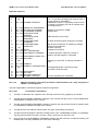
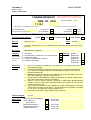
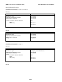
SMG7 Meeting #23
Sophia Antipolis, France, 19-22 Oct 1999
Document
CHANGE REQUEST
Please see embedded help file at the bottom of this
page for instructions on how to fill in this form correctly.
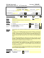
Current Version:
11.10-1 CR A696
GSM (AA.BB) or 3G (AA.BBB) specification number ↑
For submission to:
SMG #30
Form: CR cover sheet, version 2 for 3GPP and SMG
Proposed change affects:
6.1.0
↑ CR number as allocated by MCC support team
for approval
for information
list expected approval meeting # here ↑
7-99-263
e.g. for 3GPP use the format TP-99xxx
or for SMG, use the format P-99-xxx
Strategic
non-strategic
X
X
(for SMG
use only)
The latest version of this form is available from: ftp://ftp.3gpp.org/Information/CR-Form-v2.doc
(U)SIM
ME
X
Core Network
UTRAN / Radio
(at least one should be marked with an X)
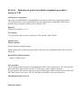
Source:
7 layers AG, Germany
Subject:
Adding of “Specific Message Contents” for GSM 1800
Work item:
HSCSD
Category:
(only one category
shall be marked
with an X)
F
A
B
C
D
Clauses affected:
Other
comments:
01.10.1999
Release:
Phase 2
Release 96
Release 97
Release 98
Release 99
Release 00
X
Test Case 26.13.1.2.2 contains a subsection for GSM 900 “Specific Message
Contents”, but a corresponding subsection for GSM 1800 messages is missing.
Reason for
change:
Other specs
affected:
Correction
Corresponds to a correction in an earlier release
Addition of feature
Functional modification of feature
Editorial modification
Date:
26.13.1.2.2.3
Other 3G core specifications
Other GSM core
specifications
MS test specifications
BSS test specifications
O&M specifications
→ List of CRs:
→ List of CRs:
→ List of CRs:
→ List of CRs:
→ List of CRs:
Same changes are necessary to other releases of same specification
help.doc
<--------- double-click here for help and instructions on how to create a CR.
X
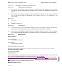
GSM 11.10-1 version 6.1.0 Release 1997
26.13.1.2.2
1173
Draft EN 300 607-1 V6.1.0 (1999-07)
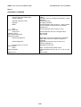
Multislot signalling / RR / Dedicated assignment / failure / general case
This test is applicable to all MS that supports multislot configuration.
26.13.1.2.2.1
Conformance requirements
On the mobile station side, if a lower layer failure happens on the new channel before the ASSIGNMENT
COMPLETE message has been sent, the mobile station deactivates the new channels, reactivates the old
channels, reconnects the TCHs if any and triggers the establishment of the main signalling link. It then
sends an ASSIGNMENT FAILURE message, cause "protocol error unspecified" on the main DCCH and
resumes the normal operation, as if no assignment attempt had occurred. The operational parameters (e.g.
ciphering mode) when returning on the old channel are those applied before the procedure.
References
Conformance requirements:
26.13.1.2.2.2
GSM 04.08 sections 3.4.3, 9.1.3 and 9.1.4
Test purpose
1)
To test that, when the MS fails to seize the new channel, the MS reactivates the old channel.
2)
This is tested in the special cases of transition:
2.1)
from non-hopping SDCCH to hopping symmetric multislot configuration
2.2)
from hopping asymmetric multislot configuration to non-hopping symmetric
2.3)
from non hopping symmetric multislot configuration to non-hopping symmetric multislot
configuration, resource upgrading used
2.4)
from non-hopping asymmetric multislot configuration to non-hopping asymmetric multislot
configuration, resource upgrading used
2.5)
from hopping symmetric multislot configuration to hopping asymmetric multislot configuration,
resource upgrading used
2.6)
from hopping asymmetric multislot configuration to non-hopping multislot configuration,
resources downgrading to one TCH/F
26.13.1.2.2.3
Method of test
Initial Conditions
System Simulator:
1 cell, default parameters.
Mobile Station:
The MS is "idle updated".
Related PICS/PIXIT Statements
-
Type of MS (P-GSM 900 or EGSM or DCS 1 800).
Multislot class
Foreseen Final State of the MS
The MS is "idle updated".
GSM 11.10-1 version 6.1.0 Release 1997
1174
Draft EN 300 607-1 V6.1.0 (1999-07)
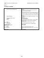
Test Procedure
A mobile terminated RR connection is established on an SDCCH. The following is repeated six times with
different parameters:
The SS sends an ASSIGNMENT COMMAND message allocating a hopping/non-hopping
symmetric/asymmetric multislot configuration with or without resource upgrading/downgrading, but does not
activate the assigned channels. The MS shall try to activate the new channel (this is not verified) and shall
then reactivate the old channel and trigger the establishment of the main signalling link on the old channel.
Then the MS shall send an ASSIGNMENT FAILURE.
The SS initiates the channel release procedure and the test ends here.
Maximum Duration of Test
30 s.
GSM 11.10-1 version 6.1.0 Release 1997
1175
Draft EN 300 607-1 V6.1.0 (1999-07)
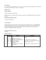
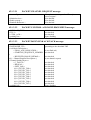
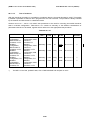
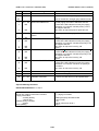
Expected Sequence
Step
1
2
3
4
5
Direction
SS -> MS
MS -> SS
SS -> MS
MS -> SS
SS -> MS
Message
PAGING REQUEST TYPE 1
CHANNEL REQUEST
IMMEDIATE ASSIGNMENT
PAGING RESPONSE
ASSIGNMENT COMMAND
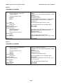
6
7
8
MS -> SS ASSIGNMENT FAILURE
SS
9
10
11
SS -> MS ASSIGNMENT COMMAND
MS -> SS ASSIGNMENT COMPLETE
SS -> MS ASSIGNMENT COMMAND
12
13
14
MS -> SS ASSIGNMENT FAILURE
SS -> MS ASSIGNMENT COMMAND
15
16
MS -> SS ASSIGNMENT COMPLETE
SS -> MS ASSIGNMENT COMMAND
17
18
19
MS -> SS ASSIGNMENT FAILURE
SS -> MS ASSIGNMENT COMMAND
20
21
MS -> SS ASSIGNMENT COMPLETE
SS -> MS ASSIGNMENT COMMAND
22
23
24
MS -> SS ASSIGNMENT FAILURE
SS -> MS ASSIGNMENT COMMAND
25
26
MS -> SS ASSIGNMENT COMPLETE
SS -> MS ASSIGNMENT COMMAND
27
28
29
MS -> SS ASSIGNMENT FAILURE
SS -> MS ASSIGNMENT COMMAND
30
MS -> SS ASSIGNMENT COMPLETE
Comments
Channel Type: SDCCH/4.
See specific message contents below. The MS
attempts (and fails) to establish a signalling link on
the new channel.
The MS re-establishes the signalling link on the old
channel.
RR cause value = “protocol error unspecified".
The SS checks that the MS reports the old power
level (prior to the Assignment command) in the
layer 1 header of the SACCH message that is sent
in the first SACCH multiframe following the SABM.
See specific message contents below.
Assignment command is successfully performed.
Channel Type = TCH/F, non-hopping, symmetric
multislot configuration. The MS attempts (and fails)
to establish a signalling link on the new channel.
The MS re-establishes the signalling link on the old
channel.
RR cause value = “protocol error unspecified".
Assignment command to non-hopping, symmetric
multislot configuration is successfully performed.
Channel Type = TCH/F, non-hopping, symmetric
multislot configuration, resource upgrading used.
The MS attempts (and fails) to establish a
signalling link on the new channel.
The MS re-establishes the signalling link on the old
channel.
RR cause value = “protocol error unspecified".
Assignment command to non-hopping, asymmetric
multislot configuration is successfully performed.
Channel Type = TCH/F, non-hopping, asymmetric
multislot configuration, resource downgrading used.
The MS attempts (and fails) to establish a
signalling link on the new channel.
The MS re-establishes the signalling link on the old
channel.
RR cause value = “protocol error unspecified".
Assignment command to hopping, symmetric
multislot configuration is successfully performed.
Channel Type = TCH/F, hopping, asymmetric
multislot configuration, resource upgrading used.
The MS attempts (and fails) to establish a
signalling link on the new channel.
The MS re-establishes the signalling link on the old
channel.
RR cause value = “protocol error unspecified".
Assignment command to hopping, asymmetric
multislot configuration is successfully performed.
GSM 11.10-1 version 6.1.0 Release 1997
31
SS -> MS ASSIGNMENT COMMAND
32
33
34
MS -> SS ASSIGNMENT FAILURE
SS -> MS CHANNEL RELEASE
1176
Draft EN 300 607-1 V6.1.0 (1999-07)
Channel Type = TCH/F, non-hopping, multislot
configuration, resources downgrading to one
TCH/F. The MS attempts (and fails) to establish a
signalling link on the new channel.
The MS re-establishes the signalling link on the old
channel.
RR cause value = “protocol error unspecified".
The main signalling link is released.
Specific Message Contents
GSM 900 begin:
Step 5:
ASSIGNMENT COMMAND
Channel Description 2
- Channel Type and TDMA offset
- Timeslot Number
- Training Sequence Code
- Hopping
- MAIO
- HSN
Power Command
- Power level
Frequency list IE
Cell Channel Description
Multislot allocation
- Downlink assignment
- Uplink assignment
- Channel set X (1=<X<=8)
Channel Mode
- Mode
Mobile Allocation
Starting Time
00000
A suitable value for multislot configuration, chosen
arbitrarily
Chosen arbitrarily
RF hopping channel
Chosen arbitrarily from the set (0, 1 to N-1) where
N is the number of frequencies in the Mobile
Allocation IE.
Chosen arbitrarily from the set (1 to 63)
Chosen arbitrarily but with a changed value.
Not Included
Bit map zero encodes (45, 46, 52, 59, 66, 73, 74,
75, 76, 108, 114)
Maximum number of symmetrical timeslots
assigned.
As many timeslots as downlink direction.
Appropriate for the test
Data, 12.0 kbit/s radio interface rate
Arbitrarily chosen from Cell channel description
Not included
GSM 11.10-1 version 6.1.0 Release 1997
1177
Draft EN 300 607-1 V6.1.0 (1999-07)
Step 9:
ASSIGNMENT COMMAND
Channel Description 2
- Channel Type and TDMA offset
- Timeslot Number
- Training Sequence Code
- Hopping
- MAIO
- HSN
Power Command
- Power level
Frequency list IE
Cell Channel Description
Multislot allocation
- Downlink assignment
- Uplink assignment
- Channel set X (1=<X<=8)
Channel Mode
- Mode
Mobile Allocation
Starting Time
00000
A suitable value for multislot configuration, chosen
arbitrarily
Chosen arbitrarily
RF hopping channel
Chosen arbitrarily from the set (0, 1 to N-1) where
N is the number of frequencies in the Mobile
Allocation IE.
Chosen arbitrarily from the set (1 to 63)
Chosen arbitrarily but with a changed value.
Not Included
Bit map zero encodes (45, 46, 52, 59, 66, 73, 74,
75, 76, 108, 114)
Maximum number of timeslots that MS supports.
Less timeslots assigned than downlink direction.
Appropriate for the test
Data, 12.0 kbit/s radio interface rate
Arbitrarily chosen from Cell channel description
Not included
Step 11:
ASSIGNMENT COMMAND
Channel Description 2
- Channel Type and TDMA offset
- Timeslot Number
- Training Sequence Code
- Hopping
- ARFCN
Power Command
- Power level
Frequency list IE
Cell Channel Description
Multislot allocation
- Downlink assignment
- Uplink assignment
- Channel set X (1=<X<=8)
Channel Mode
- Mode
Mobile Allocation
Starting Time
00000
A suitable value for multislot configuration, chosen
arbitrarily
Chosen arbitrarily
Single RF channel
the ARFCN of the BCCH carrier
Chosen arbitrarily but with a changed value.
Not Included
Bit map zero encodes (45, 46, 52, 59, 66, 73, 74,
75, 76, 108, 114)
Maximum number symmetrical of timeslots
supported by MS assigned.
As many timeslots as in downlink direction.
Appropriate for the test
Data, 12.0 kbit/s radio interface rate
Not included
Not included
GSM 11.10-1 version 6.1.0 Release 1997
1178
Draft EN 300 607-1 V6.1.0 (1999-07)
Step 14:
ASSIGNMENT COMMAND
Channel Description 2
- Channel Type and TDMA offset
- Timeslot Number
- Training Sequence Code
- Hopping
- ARFCN
Power Command
- Power level
Frequency list IE
Cell Channel Description
Multislot allocation
- Downlink assignment
- Uplink assignment
- Channel set X (1=<X<=8)
Channel Mode
- Mode
Mobile Allocation
Starting Time
00000
A suitable value for multislot configuration, chosen
arbitrarily
Chosen arbitrarily
Single RF channel
the ARFCN of the BCCH carrier
Chosen arbitrarily but with a changed value.
Not Included
Bit map zero encodes (45, 46, 52, 59, 66, 73, 74,
75, 76, 108, 114)
Only one timeslot is assigned in downlink direction.
Only one timeslot is assigned in uplink direction.
Appropriate for the test
Data, 12.0 kbit/s radio interface rate
Not included
Not included
Step 16:
ASSIGNMENT COMMAND
Channel Description 2
- Channel Type and TDMA offset
- Timeslot Number
- Training Sequence Code
- Hopping
- ARFCN
Power Command
- Power level
Frequency list IE
Cell Channel Description
Multislot allocation
- Downlink assignment
- Uplink assignment
- Channel set X (1=<X<=8)
Channel Mode
- Mode
Mobile Allocation
Starting Time
00000
A suitable value for multislot configuration, chosen
arbitrarily
Chosen arbitrarily
Single RF channel
the ARFCN of the BCCH carrier
Chosen arbitrarily but with a changed value.
Not Included
Bit map zero encodes (45, 46, 52, 59, 66, 73, 74,
75, 76, 108, 114)
Maximum number of timeslots that MS supports.
Maximum number of timeslots that MS supports.
Appropriate for the test
Data, 12.0 kbit/s radio interface rate
Not included
Not included
GSM 11.10-1 version 6.1.0 Release 1997
1179
Draft EN 300 607-1 V6.1.0 (1999-07)
Step 19:
ASSIGNMENT COMMAND
Channel Description 2
- Channel Type and TDMA offset
- Timeslot Number
- Training Sequence Code
- Hopping
- ARFCN
Power Command
- Power level
Frequency list IE
Cell Channel Description
Multislot allocation
- Downlink assignment
- Uplink assignment
- Channel set X (1=<X<=8)
Channel Mode
- Mode
Mobile Allocation
Starting Time
00000
A suitable value for multislot configuration, chosen
arbitrarily
Chosen arbitrarily
Single RF channel
the ARFCN of the BCCH carrier
Chosen arbitrarily but with a changed value.
Not Included
Bit map zero encodes (45, 46, 52, 59, 66, 73, 74,
75, 76, 108, 114)
More than one timeslot but less than maximum
number of timeslots is assigned in downlink
direction.
Only one timeslot is assigned in uplink direction.
Appropriate for the test
Data, 12.0 kbit/s radio interface rate
Not included
Not included
Step 21:
ASSIGNMENT COMMAND
Channel Description 2
- Channel Type and TDMA offset
- Timeslot Number
- Training Sequence Code
- Hopping
- ARFCN
Power Command
- Power level
Frequency list IE
Cell Channel Description
Multislot allocation
- Downlink assignment
- Uplink assignment
- Channel set X (1=<X<=8)
Channel Mode
- Mode
Mobile Allocation
Starting Time
00000
A suitable value for multislot configuration, chosen
arbitrarily
Chosen arbitrarily
Single RF channel
the ARFCN of the BCCH carrier
Chosen arbitrarily but with a changed value.
Not Included
Bit map zero encodes (45, 46, 52, 59, 66, 73, 74,
75, 76, 108, 114)
Maximum number of timeslots that MS supports.
Less timeslots assigned than downlink direction.
Appropriate for the test
Data, 12.0 kbit/s radio interface rate
Not included
Not included
GSM 11.10-1 version 6.1.0 Release 1997
1180
Draft EN 300 607-1 V6.1.0 (1999-07)
Step 24:
ASSIGNMENT COMMAND
Channel Description 2
- Channel Type and TDMA offset
- Timeslot Number
- Training Sequence Code
- Hopping
- MAIO
- HSN
Power Command
- Power level
Frequency list IE
Cell Channel Description
Multislot allocation
- Downlink assignment
- Uplink assignment
- Channel set X (1=<X<=8)
Channel Mode
- Mode
Mobile Allocation
Starting Time
00000
A suitable value for multislot configuration, chosen
arbitrarily
Chosen arbitrarily
RF hopping channel
Chosen arbitrarily from the set (0, 1 to N-1) where
N is the number of frequencies in the Mobile
Allocation IE.
Chosen arbitrarily from the set (1 to 63)
Chosen arbitrarily but with a changed value.
Not Included
Bit map zero encodes (45, 46, 52, 59, 66, 73, 74,
75, 76, 108, 114)
Only one timeslot is assigned in downlink direction.
Only one timeslot is assigned in uplink direction.
Appropriate for the test
Data, 12.0 kbit/s radio interface rate
Chosen arbitrarily from the Cell channel
description
Not included
Step 26:
ASSIGNMENT COMMAND
Channel Description 2
- Channel Type and TDMA offset
- Timeslot Number
- Training Sequence Code
- Hopping
- MAIO
- HSN
Power Command
- Power level
Frequency list IE
Cell Channel Description
Multislot allocation
- Downlink assignment
- Uplink assignment
- Channel set X (1=<X<=8)
Channel Mode
- Mode
Mobile Allocation
Starting Time
00000
A suitable value for multislot configuration, chosen
arbitrarily
Chosen arbitrarily
RF hopping channel
Chosen arbitrarily from the set (0, 1 to N-1) where
N is the number of frequencies in the Mobile
Allocation IE.
Chosen arbitrarily from the set (1 to 63)
Chosen arbitrarily but with a changed value.
Not Included
Bit map zero encodes (45, 46, 52, 59, 66, 73, 74,
75, 76, 108, 114)
Maximum number of timeslots that MS supports.
Less timeslots assigned than in downlink direction.
Appropriate for the test
Data, 12.0 kbit/s radio interface rate
Chosen arbitrarily from the Cell channel
description
Not included
GSM 11.10-1 version 6.1.0 Release 1997
1181
Draft EN 300 607-1 V6.1.0 (1999-07)
Step 29:
ASSIGNMENT COMMAND
Channel Description 2
- Channel Type and TDMA offset
- Timeslot Number
- Training Sequence Code
- Hopping
- MAIO
- HSN
Power Command
- Power level
Frequency list IE
Cell Channel Description
Multislot allocation
- Downlink assignment
- Uplink assignment
- Channel set X (1=<X<=8)
Channel Mode
- Mode
Mobile Allocation
Starting Time
00000
A suitable value for multislot configuration, chosen
arbitrarily
Chosen arbitrarily
RF hopping channel
Chosen arbitrarily from the set (0, 1 to N-1) where
N is the number of frequencies in the Mobile
Allocation IE.
Chosen arbitrarily from the set (1 to 63)
Chosen arbitrarily but with a changed value.
Not Included
Bit map zero encodes (45, 46, 52, 59, 66, 73, 74,
75, 76, 108, 114)
Maximum number of timeslots that MS supports.
Less timeslots assigned than in downlink direction.
Appropriate for the test
Data, 12.0 kbit/s radio interface rate
Chosen arbitrarily from the Cell channel
description
Not included
Step 31:
ASSIGNMENT COMMAND
Channel Description 2
- Channel Type and TDMA offset
- Timeslot Number
- Training Sequence Code
- Hopping
- ARFCN
Power Command
- Power level
Frequency list IE
Cell Channel Description
Multislot allocation
- Downlink assignment
- Uplink assignment
- Channel set X (1=<X<=8)
Channel Mode
- Mode
Mobile Allocation
Starting Time
00000
A suitable value for multislot configuration, chosen
arbitrarily
Chosen arbitrarily
Single RF channel
the ARFCN of the BCCH carrier
Chosen arbitrarily but with a changed value.
Not Included
Bit map zero encodes (45, 46, 52, 59, 66, 73, 74,
75, 76, 108, 114)
Only one timeslot is assigned in downlink direction.
Only one timeslot is assigned in uplink direction.
Appropriate for the test
Data, 12.0 kbit/s radio interface rate
Not included
Not included
GSM 11.10-1 version 6.1.0 Release 1997
1182
Draft EN 300 607-1 V6.1.0 (1999-07)
GSM 900 end:
GSM 1800 begin:
Step 5:
ASSIGNMENT COMMAND
Channel Description 2
- Channel Type and TDMA offset
- Timeslot Number
- Training Sequence Code
- Hopping
- MAIO
- HSN
Power Command
- Power level
Frequency list IE
Cell Channel Description
Multislot allocation
- Downlink assignment
- Uplink assignment
- Channel set X (1=<X<=8)
Channel Mode
- Mode
Mobile Allocation
Starting Time
00000
A suitable value for multislot configuration, chosen
arbitrarily
Chosen arbitrarily
RF hopping channel
Chosen arbitrarily from the set (0, 1 to N-1) where
N is the number of frequencies in the Mobile
Allocation IE.
Chosen arbitrarily from the set (1 to 63)
Chosen arbitrarily but with a changed value.
Not Included
Use Range 128 to encode (773, 775, 779, 782,
791, 798, 829, 832, 844)
Maximum number of symmetrical timeslots
assigned.
As many timeslots as downlink direction.
Appropriate for the test
Data, 12.0 kbit/s radio interface rate
Arbitrarily chosen from Cell channel description
Not included
GSM 11.10-1 version 6.1.0 Release 1997
1183
Draft EN 300 607-1 V6.1.0 (1999-07)
Step 9:
ASSIGNMENT COMMAND
Channel Description 2
- Channel Type and TDMA offset
- Timeslot Number
- Training Sequence Code
- Hopping
- MAIO
- HSN
Power Command
- Power level
Frequency list IE
Cell Channel Description
Multislot allocation
- Downlink assignment
- Uplink assignment
- Channel set X (1=<X<=8)
Channel Mode
- Mode
Mobile Allocation
Starting Time
00000
A suitable value for multislot configuration, chosen
arbitrarily
Chosen arbitrarily
RF hopping channel
Chosen arbitrarily from the set (0, 1 to N-1) where
N is the number of frequencies in the Mobile
Allocation IE.
Chosen arbitrarily from the set (1 to 63)
Chosen arbitrarily but with a changed value.
Not Included
Use Range 128 to encode (773, 775, 779, 782,
791, 798, 829, 832, 844)
Maximum number of timeslots that MS supports.
Less timeslots assigned than downlink direction.
Appropriate for the test
Data, 12.0 kbit/s radio interface rate
Arbitrarily chosen from Cell channel description
Not included
Step 11:
ASSIGNMENT COMMAND
Channel Description 2
- Channel Type and TDMA offset
- Timeslot Number
- Training Sequence Code
- Hopping
- ARFCN
Power Command
- Power level
Frequency list IE
Cell Channel Description
Multislot allocation
- Downlink assignment
- Uplink assignment
- Channel set X (1=<X<=8)
Channel Mode
- Mode
Mobile Allocation
Starting Time
00000
A suitable value for multislot configuration, chosen
arbitrarily
Chosen arbitrarily
Single RF channel
the ARFCN of the BCCH carrier
Chosen arbitrarily but with a changed value.
Not Included
Use Range 128 to encode (773, 775, 779, 782,
791, 798, 829, 832, 844)
Maximum number symmetrical of timeslots
supported by MS assigned.
As many timeslots as in downlink direction.
Appropriate for the test
Data, 12.0 kbit/s radio interface rate
Not included
Not included
GSM 11.10-1 version 6.1.0 Release 1997
1184
Draft EN 300 607-1 V6.1.0 (1999-07)
Step 14:
ASSIGNMENT COMMAND
Channel Description 2
- Channel Type and TDMA offset
- Timeslot Number
- Training Sequence Code
- Hopping
- ARFCN
Power Command
- Power level
Frequency list IE
Cell Channel Description
Multislot allocation
- Downlink assignment
- Uplink assignment
- Channel set X (1=<X<=8)
Channel Mode
- Mode
Mobile Allocation
Starting Time
00000
A suitable value for multislot configuration, chosen
arbitrarily
Chosen arbitrarily
Single RF channel
the ARFCN of the BCCH carrier
Chosen arbitrarily but with a changed value.
Not Included
Use Range 128 to encode (773, 775, 779, 782,
791, 798, 829, 832, 844)
Only one timeslot is assigned in downlink direction.
Only one timeslot is assigned in uplink direction.
Appropriate for the test
Data, 12.0 kbit/s radio interface rate
Not included
Not included
Step 16:
ASSIGNMENT COMMAND
Channel Description 2
- Channel Type and TDMA offset
- Timeslot Number
- Training Sequence Code
- Hopping
- ARFCN
Power Command
- Power level
Frequency list IE
Cell Channel Description
Multislot allocation
- Downlink assignment
- Uplink assignment
- Channel set X (1=<X<=8)
Channel Mode
- Mode
Mobile Allocation
Starting Time
00000
A suitable value for multislot configuration, chosen
arbitrarily
Chosen arbitrarily
Single RF channel
the ARFCN of the BCCH carrier
Chosen arbitrarily but with a changed value.
Not Included
Use Range 128 to encode (773, 775, 779, 782,
791, 798, 829, 832, 844)
Maximum number of timeslots that MS supports.
Maximum number of timeslots that MS supports.
Appropriate for the test
Data, 12.0 kbit/s radio interface rate
Not included
Not included
GSM 11.10-1 version 6.1.0 Release 1997
1185
Draft EN 300 607-1 V6.1.0 (1999-07)
Step 19:
ASSIGNMENT COMMAND
Channel Description 2
- Channel Type and TDMA offset
- Timeslot Number
- Training Sequence Code
- Hopping
- ARFCN
Power Command
- Power level
Frequency list IE
Cell Channel Description
Multislot allocation
- Downlink assignment
- Uplink assignment
- Channel set X (1=<X<=8)
Channel Mode
- Mode
Mobile Allocation
Starting Time
00000
A suitable value for multislot configuration, chosen
arbitrarily
Chosen arbitrarily
Single RF channel
the ARFCN of the BCCH carrier
Chosen arbitrarily but with a changed value.
Not Included
Use Range 128 to encode (773, 775, 779, 782,
791, 798, 829, 832, 844)
More than one timeslot but less than maximum
number of timeslots is assigned in downlink
direction.
Only one timeslot is assigned in uplink direction.
Appropriate for the test
Data, 12.0 kbit/s radio interface rate
Not included
Not included
Step 21:
ASSIGNMENT COMMAND
Channel Description 2
- Channel Type and TDMA offset
- Timeslot Number
- Training Sequence Code
- Hopping
- ARFCN
Power Command
- Power level
Frequency list IE
Cell Channel Description
Multislot allocation
- Downlink assignment
- Uplink assignment
- Channel set X (1=<X<=8)
Channel Mode
- Mode
Mobile Allocation
Starting Time
00000
A suitable value for multislot configuration, chosen
arbitrarily
Chosen arbitrarily
Single RF channel
the ARFCN of the BCCH carrier
Chosen arbitrarily but with a changed value.
Not Included
Use Range 128 to encode (773, 775, 779, 782,
791, 798, 829, 832, 844)
Maximum number of timeslots that MS supports.
Less timeslots assigned than downlink direction.
Appropriate for the test
Data, 12.0 kbit/s radio interface rate
Not included
Not included
GSM 11.10-1 version 6.1.0 Release 1997
1186
Draft EN 300 607-1 V6.1.0 (1999-07)
Step 24:
ASSIGNMENT COMMAND
Channel Description 2
- Channel Type and TDMA offset
- Timeslot Number
- Training Sequence Code
- Hopping
- MAIO
- HSN
Power Command
- Power level
Frequency list IE
Cell Channel Description
Multislot allocation
- Downlink assignment
- Uplink assignment
- Channel set X (1=<X<=8)
Channel Mode
- Mode
Mobile Allocation
Starting Time
00000
A suitable value for multislot configuration, chosen
arbitrarily
Chosen arbitrarily
RF hopping channel
Chosen arbitrarily from the set (0, 1 to N-1) where
N is the number of frequencies in the Mobile
Allocation IE.
Chosen arbitrarily from the set (1 to 63)
Chosen arbitrarily but with a changed value.
Not Included
Use Range 128 to encode (773, 775, 779, 782,
791, 798, 829, 832, 844)
Only one timeslot is assigned in downlink direction.
Only one timeslot is assigned in uplink direction.
Appropriate for the test
Data, 12.0 kbit/s radio interface rate
Chosen arbitrarily from the Cell channel
description
Not included
Step 26:
ASSIGNMENT COMMAND
Channel Description 2
- Channel Type and TDMA offset
- Timeslot Number
- Training Sequence Code
- Hopping
- MAIO
- HSN
Power Command
- Power level
Frequency list IE
Cell Channel Description
Multislot allocation
- Downlink assignment
- Uplink assignment
- Channel set X (1=<X<=8)
Channel Mode
- Mode
Mobile Allocation
Starting Time
00000
A suitable value for multislot configuration, chosen
arbitrarily
Chosen arbitrarily
RF hopping channel
Chosen arbitrarily from the set (0, 1 to N-1) where
N is the number of frequencies in the Mobile
Allocation IE.
Chosen arbitrarily from the set (1 to 63)
Chosen arbitrarily but with a changed value.
Not Included
Use Range 128 to encode (773, 775, 779, 782,
791, 798, 829, 832, 844)
Maximum number of timeslots that MS supports.
Less timeslots assigned than in downlink direction.
Appropriate for the test
Data, 12.0 kbit/s radio interface rate
Chosen arbitrarily from the Cell channel
description
Not included
GSM 11.10-1 version 6.1.0 Release 1997
1187
Draft EN 300 607-1 V6.1.0 (1999-07)
Step 29:
ASSIGNMENT COMMAND
Channel Description 2
- Channel Type and TDMA offset
- Timeslot Number
- Training Sequence Code
- Hopping
- MAIO
- HSN
Power Command
- Power level
Frequency list IE
Cell Channel Description
Multislot allocation
- Downlink assignment
- Uplink assignment
- Channel set X (1=<X<=8)
Channel Mode
- Mode
Mobile Allocation
Starting Time
00000
A suitable value for multislot configuration, chosen
arbitrarily
Chosen arbitrarily
RF hopping channel
Chosen arbitrarily from the set (0, 1 to N-1) where
N is the number of frequencies in the Mobile
Allocation IE.
Chosen arbitrarily from the set (1 to 63)
Chosen arbitrarily but with a changed value.
Not Included
Use Range 128 to encode (773, 775, 779, 782,
791, 798, 829, 832, 844)
Maximum number of timeslots that MS supports.
Less timeslots assigned than in downlink direction.
Appropriate for the test
Data, 12.0 kbit/s radio interface rate
Chosen arbitrarily from the Cell channel
description
Not included
Step 31:
ASSIGNMENT COMMAND
Channel Description 2
- Channel Type and TDMA offset
- Timeslot Number
- Training Sequence Code
- Hopping
- ARFCN
Power Command
- Power level
Frequency list IE
Cell Channel Description
Multislot allocation
- Downlink assignment
- Uplink assignment
- Channel set X (1=<X<=8)
Channel Mode
- Mode
Mobile Allocation
Starting Time
GSM 1800 end:
00000
A suitable value for multislot configuration, chosen
arbitrarily
Chosen arbitrarily
Single RF channel
the ARFCN of the BCCH carrier
Chosen arbitrarily but with a changed value.
Not Included
Use Range 128 to encode (773, 775, 779, 782,
791, 798, 829, 832, 844)
Only one timeslot is assigned in downlink direction.
Only one timeslot is assigned in uplink direction.
Appropriate for the test
Data, 12.0 kbit/s radio interface rate
Not included
Not included
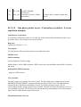
ETSI SMG7
Tdoc SMG7-99-271
Sophia Antipolis
19-22 October 1999
CHANGE REQUEST No :
Technical Specification GSM / UMTS:
Submitted to SMG
#30
list plenary meeting or STC here ↑
11.10-1
for approval
for information
Please see embedded help file at the bottom of this
page for instructions on how to fill in this form correctly.
A698
Version
6.1.0
without presentation ("non-strategic")
with presentation ("strategic")
X
X
PT SMG CR cover form. Filename: crf26_3.doc
Proposed change affects:
SIM
ME
X
Network
(at least one should be marked with an X)
Work item:
GPRS
Source:
Motorola
Subject:
Cell reselection test 20.22.2
Category:
F
A
B
C
D
(one category
and one release
only shall be
Date:
Correction
Corresponds to a correction in an earlier release
Addition of feature
Functional modification of feature
Editorial modification
X
Release:
marked with an X)
Reason for
change:
Phase 2
Release 96
Release 97
Release 98
Release 99
UMTS
X
A carrier is not enabled in the procedure section which is needed for the test to work
correctly.
Clauses affected:
Other specs
affected:
18/09/99
20.22.2.4.2
Other releases of same spec
Other core specifications
MS test specifications / TBRs
BSS test specifications
O&M specifications
→
→
→
→
→
List of
List of
List of
List of
List of
CRs:
CRs:
CRs:
CRs:
CRs:
Other
comments:
help.doc
<--------- double-click here for help and instructions on how to create a CR.
20.22.2.4.2
Procedure
a) The SS activates carriers 1,2 and 5. and 2. The MS is paged on Carriers 1 and 2. The SS starts
monitoring carriers 1 and 2 for RA requests from the MS.
b) The MS is switched on.
c) The SS activates carriers 3 and 4. The MS is paged on both carriers. The SS monitors carriers 3 and 4
for RA requests from the MS.
ETSI SMG7
Tdoc SMG7-99-272
Sophia Antipolis
19-22 October 1999
CHANGE REQUEST No :
Technical Specification GSM / UMTS:
Submitted to SMG
#30
list plenary meeting or STC here ↑
11.10-1
for approval
for information
Please see embedded help file at the bottom of this
page for instructions on how to fill in this form correctly.
A700
Version
6.1.0
without presentation ("non-strategic")
with presentation ("strategic")
X
X
PT SMG CR cover form. Filename: crf26_3.doc
Proposed change affects:
SIM
ME
X
Network
(at least one should be marked with an X)
Work item:
GPRS
Source:
Motorola
Subject:
Cell reselection test 20.22.4
Category:
F
A
B
C
D
(one category
and one release
only shall be
Date:
Correction
Corresponds to a correction in an earlier release
Addition of feature
Functional modification of feature
Editorial modification
X
Release:
marked with an X)
Reason for
change:
Phase 2
Release 96
Release 97
Release 98
Release 99
UMTS
The initial conditions table in test 20.22.4.4.1 has incorrectly calculated values for C32
As C32 = C1+GRO – RARH, the value of GRO was not added to the value of C1
Clauses affected:
Other specs
affected:
18/09/99
20.22.4.4.1
Other releases of same spec
Other core specifications
MS test specifications / TBRs
BSS test specifications
O&M specifications
→
→
→
→
→
List of
List of
List of
List of
List of
CRs:
CRs:
CRs:
CRs:
CRs:
Other
comments:
help.doc
<--------- double-click here for help and instructions on how to create a CR.
X
20.22.4.4
Method of Test
20.22.4.4.1
Initial Conditions
Parameters changed from the default values in table 20.22.1.
Parameter
RF Signal Level (dBm)
RAI
GPRS_RXLEV_ACCESS_MIN (dBm)
Carrier 1 Carrier 2 Carrier 3 Carrier 4 Carrier 5 Carrier 6
-60
-60
-70
-70
-70
-70
Different
-100
-100
-80
-100
-100
-80
GRO
GCRH
RARH
C1
C32
4
14
40 to 15
40 to 15
4
4
6
4
10
140
30
340
30
22
10
140
Note1 : GRO = GPRS_RESELECT_OFFSET, GCRH = GPRS_CELL_RESELECT_HYSTERESIS, RARH
= RA_RESELECT_HYSTERESIS.
Note 2 : The BA(GPRS) list only contains the ARFCNs of the carriers used during the test. The HCS
structure is transmitted in the Packet system information messages.
Note 3 : Carrier 1 is the BCCH carrier which broadcasts the position of the PBCCH channel in the cell
(Carrier 2.)
ETSI SMG7
Tdoc SMG7-99-273
Sophia Antipolis
19-22 October 1999
CHANGE REQUEST No :
Technical Specification GSM / UMTS:
Submitted to SMG
#30
list plenary meeting or STC here ↑
11.10-1
for approval
for information
Please see embedded help file at the bottom of this
page for instructions on how to fill in this form correctly.
A702
Version
6.1.0
without presentation ("non-strategic")
with presentation ("strategic")
X
X
PT SMG CR cover form. Filename: crf26_3.doc
Proposed change affects:
SIM
ME
X
Network
(at least one should be marked with an X)
Work item:
GPRS
Source:
Motorola
Subject:
Cell reselection test 20.22.6
Category:
F
A
B
C
D
(one category
and one release
only shall be
Date:
Correction
Corresponds to a correction in an earlier release
Addition of feature
Functional modification of feature
Editorial modification
X
Release:
marked with an X)
Reason for
change:
Phase 2
Release 96
Release 97
Release 98
Release 99
UMTS
X
The wrong carrier is used in test procedure which would cause the test to fail, also the
initial conditions are incorrect.
Clauses affected:
Other specs
affected:
18/09/99
20.22.6.4.1, 20.22.6.4.2, 20.22.6.5
Other releases of same spec
Other core specifications
MS test specifications / TBRs
BSS test specifications
O&M specifications
→
→
→
→
→
List of
List of
List of
List of
List of
CRs:
CRs:
CRs:
CRs:
CRs:
Other
comments:
help.doc
<--------- double-click here for help and instructions on how to create a CR.
20.22.6.4.1 Initial Conditions
Parameters changed from the default values in table 20.22.1.
Parameter
RF Signal Level (dBm)
GPRS_RXLEV_ACCESS_MIN (dBm)
GRO
SPLIT_PG_CYCLE
C1
C32
Carrier 1
-670
-90
-20
4
Carrier 2
-670
-90
320
30
4
Carrier 3 Carrier 4
-760
-760
-100
-100
-28
4
4
340
240
Note 1 : The HCS structure is omitted from the system information messages on all the cells. Therefore
C31 is not used.
Note 2 : The RLA_P should be updated every 3.84 seconds with SPLIT_PG_CYCLE=4
Note 3 : Carriers 1 and 3 are the BCCH carriers which broadcast the position of the PBCCH channel in
the cell (Carriers 2 and 4)
20.22.6.4.2
Procedure
a)
The SS activates all carriers and pages the MS on carrier 4. The SS starts to monitor carriers 3 and 4
for responses from the MS.
b)
The MS is switched on.
c)
The SS waits 30s before the RF level of carriers 1 & 2 are reduced to –100 dBm for 8 seconds. (During
this period C1 becomes –10 ). Then the SS raises the level back to –60 dBm.The SS waits 20
seconds.
d)
The SS reduces the RF level on carriers 1 & 2 to –100dBm. for 20 seconds.
20.22.6.5
Test Requirements
1) After step c) there shall be no access on carrier 3 or carrier 4.
2) After step d) there shall be access on carrier 41 within 25 seconds ( allow 20s for c1 average to reach –
10 + 2s to decode BCCH + 2s to decode PBCCH)
Tdoc 7-99-280
ETSI SMG7
Sophia Antipolis
19th-22nd October 1999
CHANGE REQUEST No :
Technical Specification GSM
Submitted to SMG
#30
11.10-1
for approval
for information
list SMG plenary meeting no. here ↑
A706
Version:
X
6.1.0
without presentation ("non-strategic")
with presentation ("strategic")
X
PT SMG CR cover form is available from: http://docbox.etsi.org/tech-org/smg/Document/smg/tools/CR_form/crf28_1.zip
Proposed change affects:
SIM
ME
Network
Work item:
DE/SMG-00110P-1
Source:
Anite (Ref CR 1386p1)
Subject:
Stop paging in carrier 2 in the EGSM path in test case 20.5 and 20.21.5
Category:
F
A
B
C
D
(one category
and one release
only shall be
Date:
Correction
Corresponds to a correction in an earlier release
Addition of feature
Functional modification of feature
Editorial modification
Release:
X
st
21 July 1999
Phase 2
Release 96
Release 97
Release 98
Release 99
X
marked with an X)
Reason for
change:
This problem was initiated with AniteMail 1386 and confirmed with STF79mail 99443.
There is a problem in the EGSM path of 20.5, when the MS is accessing carrier 2. The
MS correctly RACHs on carrier 2 within 20 seconds of its level being increased.
Currently, the test then waits for 30 seconds before increasing the level of carrier 3 and
expects the MS to RACH on carrier 3 within 20 seconds.
However, after the MS has sent M+1 Channel Requests on carrier 2 and received no
Immediate Assignment message, it performs a cell reselection back to carrier 1 (ref:
GSM 04.08, section 3.3.1.2 Initiation of the Immediate Assignment procedure). After 5
seconds the MS re-selects to carrier 2, sends M+1 Channel Requests and re-selects to
carrier 1 again. This change between carrier 1 and carrier 2 occurs during the 30
seconds waiting period. As a consequence it not possible for the MS to meet the 20
seconds requirement at the end of the test.
To resolve this problem, the paging on carrier 2 should be stopped as soon as the MS
has sent the first Channel Request on this channel. This will ensure that it selects carrier
1 for 5 seconds and then reverts to and camps on carrier 2 for the remaining part of the
30 seconds waiting period. When the power on carrier 3 is increased, the MS will be
ready to select this channel as it will have received the ARFCN of carrier 3 in the SI 2ter
message broadcast on carrier 2, thus completing the test successfully.
This principle has already been implemented in the cell selection test cases 20.4 and
20.6.
Clauses affected:
Other specs
affected:
20.5, 20.21.5
Other releases of same spec
Other core specifications
MS test specifications / TBRs
BSS test specifications
O&M specifications
→
→
→
→
→
List of
List of
List of
List of
List of
CRs:
CRs:
CRs:
CRs:
CRs:
Other
comments:
This change also affects RGSM test case 20.21.5
(GSM 11.10-1 version 6.1.0 Release 1997)
20.5
300
Draft EN 300 607-1 V6.1.0 (1999-07)
Cell reselection using parameters transmitted in the System Information type 2bis, type
2ter, type 7 and type 8 messages
20.5.1
Definition and applicability
System information (SI) type 7 and 8 are transmitted on the BCCH Ext when the system information type
4 message does not contain all information needed for cell selection.
The system information type 2 bis message is used when the system information type 2 message does
not contain all neighbour cell ARFCNs.
The system information type 2 ter message is used when system information type 2 messages broadcast
by one cell which are system information 2 or both system information 2 and 2bis do not contain all
neighbour cell ARFCNs.
Test purposes 1 and 3 are applicable to all types of GSM900 and DCS1800 MS.
Test purpose 2 is only applicable for E-GSM and DCS 1 800 MS. This is reflected in initial conditions
step d).
Test purpose 4 is only applicable to an E-GSM MS. This is reflected in initial conditions step f), test
procedures d) and e) and test requirements clause 3).
20.5.2
Conformance requirement
1.
The MS shall be able to calculate correctly the path loss criterion parameter C2 used for cell
reselection. GSM 05.08, 6.4.
2
Whilst in idle mode, an MS shall continue to monitor all BCCH carriers as indicated by the BCCH
allocation. GSM 05.08, 6.6.1.
3
Mobile stations shall treat all ARFCNs in the set {0, 1, 2 ... 1023} as valid ARFCN values even if
the mobile station is unable to transmit or receive on that ARFCN. GSM 04.08, 10.5.2.1b.
4
An E-GSM MS shall correctly decodes parameters transmitted in the system information type 2 ter
message. GSM 04.08, 9.1.34:
20.5.3
Test purpose
1.
To verify that the MS correctly calculates the C2 criterion when the parameters affecting cell
reselection are transmitted in the system information type 7 and 8 messages.
2.
To verify that E-GSM and DCS 1 800 MS decode parameters transmitted in the system
information type 2 bis message.
3.
To verify that the MS treats ARFCNs as valid ARFCNs even if the MS is unable to transmit or
receive on that ARFCN.
4.
To verify that an E-GSM mobile correctly decode parameters transmitted in the system
information type 2 ter message.
20.5.4
Method of test
20.5.4.1
Initial conditions
a)
Parameters changed from the default values in table 20.1.
(GSM 11.10-1 version 6.1.0 Release 1997)
Parameter
RF Signal Level
(dBµV emf() / dBm )
RXLEV_ACCESS_MIN
(dBµV emf() / dBm)
BS_AG_BLKS_RES
PT
CRO
TO
301
Draft EN 300 607-1 V6.1.0 (1999-07)
Carrier 1
53 / -60
Carrier 2
32 / -81
23 / -90
23 / -90
30 / -83
1
1
0
16 dB
0 dB
1
0
10 dB
0 dB
30
30
9
25
10
20
C1
C2
Carrier 3 *)
40 / -73
Carrier 4
OFF
Carrier 5
OFF
Carrier 6
OFF
)
* : Carrier 3 is off for P-GSM and DCS 1800 MS. Carrier 3 is only required for E-GSM MS.
b)
The ARFCNs of carriers 1, 2 and 3 are chosen from those in table 20.1.
c)
The cell reselection parameters PENALTY_TIME, CELL_RESELECT_OFFSET and
TEMPORARY_OFFSET are transmitted in the SI3, SI7 and SI8 messages on carrier 2. They are
not transmitted in SI4 and the ADDITIONAL RESELECT PARAM IND parameter is set to 1.
d)
The SI2bis message is transmitted on carrier 1 and contains the ARFCN of carrier 2 and ARFCNs
43, 70, 500, 550, 990 and 995. For an E-GSM MS and a DCS 1 800 MS, the ARFCN of carrier 2 is
not transmitted in the SI2 message.
e)
Carriers 1 and 2 are synchronized, but staggered in frame number so that the transmission of the
SI3 message on carrier 2, coincides with the paging block which the MS is listening to on carrier 1.
NOTE:
Under these conditions, the MS can only decode the parameters affecting cell
reselection from the SI7 or SI8 messages.
To achieve this, the following conditions are used:
BS_PA_MFRMS = 4
IMSI mod 1000 = 12
FN carrier 1 = FN carrier 2-21, for simultaneously transmitted frames.
f)
For an E-GSM MS, the SI3 message on carrier 2 indicates that SI2ter is used on carrier 2. SI2ter
message contains the ARFCN of carrier 3 and ARFCNs 45, 76, 891, 905. The ARFCN of carrier 3
is transmitted neither in the SI2 nor in the SI2bis messages on carriers 1 and 2.
20.5.4.2
Test Procedure
a)
The SS activates the channels. The MS is not paged on carrier 1.
b)
The MS is switched on.
c)
After 50 seconds, the SS increases the level of carrier 2 to 42 dBµVemf( ).
d)
For an E-GSM MS only, when the SS receives a response on carrier 2, the SS stops paging on
that carrier and after 30 seconds, the SS increases the level of carrier 3 to 60 dBµVemf( ).
20.5.5
Test Requirements
1)
After step b), there shall be no response from the MS on carrier 2. For an E-GSM MS there shall
also be no response on carrier 3.
2)
After increasing the level of carrier 2 in step c), the MS shall respond on carrier 2 within 20
seconds.
3)
After increasing the level of carrier 3 in step d), an E-GSM mobile shall respond on carrier 3 within
20 seconds.
(GSM 11.10-1 version 6.1.0 Release 1997)
302
Draft EN 300 607-1 V6.1.0 (1999-07)
(GSM 11.10-1 version 6.1.0 Release 1997)
20.21.5
20.21.5.1
333
Draft EN 300 607-1 V6.1.0 (1999-07)
R-GSM cell reselection using parameters transmitted in the System Information type
2bis, type 2ter, type 7 and type 8 messages
Definition and applicability
System information (SI) type 7 and 8 are transmitted on the BCCH Ext when the system information type
4 message does not contain all information needed for cell selection.
The system information type 2 bis message is used when the system information type 2 message does
not contain all neighbour cell ARFCNs.
The system information type 2 ter message is used when system information type 2 messages broadcast
by one cell which are system information 2 or both system information 2 and 2bis do not contain all
neighbour cell ARFCNs.
20.21.5.2
Conformance requirement
1.
The MS shall be able to calculate correctly the path loss criterion parameter C2 used for cell
reselection. GSM 05.08, 6.4.
2
Whilst in idle mode, an MS shall continue to monitor all BCCH carriers as indicated by the BCCH
allocation. GSM 05.08, 6.6.1.
3
Mobile stations shall treat all ARFCNs in the set {0, 1, 2 ... 1023} as valid ARFCN values even if
the mobile station is unable to transmit or receive on that ARFCN. GSM 04.08, 10.5.2.1b.
4
The MS shall correctly decodes parameters transmitted in the system information type 2 ter
message. GSM 04.08, 9.1.34:
20.21.5.3
Test purpose
1.
To verify that the MS correctly calculates the C2 criterion when the parameters affecting cell
reselection are transmitted in the system information type 7 and 8 messages.
2.
To verify that the MS decodes parameters transmitted in the system information type 2 bis
message.
3.
To verify that the MS treats ARFCNs as valid ARFCNs even if the MS is unable to transmit or
receive on that ARFCN.
4.
To verify that the MS correctly decodes parameters transmitted in the system information type 2
ter message.
20.21.5.4
Method of test
20.21.5.4.1
Initial conditions
a)
Parameters changed from the default values in table 20.21.1.
Parameter
RF Signal Level
(dBµV emf() / dBm )
RXLEV_ACCESS_MIN
(dBµV emf() / dBm)
BS_AG_BLKS_RES
PT
CRO
TO
C1
C2
Carrier 1
53 / -60
Carrier 2
32 / -81
Carrier 3
40 / -73
23 / -90
23 / -90
30 / -83
1
1
0
16 dB
0 dB
1
0
10 dB
0 dB
30
30
9
25
10
20
Carrier 4
OFF
Carrier 5
OFF
Carrier 6
OFF
(GSM 11.10-1 version 6.1.0 Release 1997)
334
Draft EN 300 607-1 V6.1.0 (1999-07)
.
b)
The ARFCNs of carriers 1, 2 and 3 are chosen from those in table 20.21.1 with carrier 3 chosen
between ARFCN 955 - 974.
c)
The cell reselection parameters PENALTY_TIME, CELL_RESELECT_OFFSET and
TEMPORARY_OFFSET are transmitted in the SI3, SI7 and SI8 messages on carrier 2. They are
not transmitted in SI4 and the ADDITIONAL RESELECT PARAM IND parameter is set to 1.
d)
The SI2bis message is transmitted on carrier 1 and contains the ARFCN of carrier 2 and ARFCNs
43, 70, 500, 550, 958, 963, 990 and 995. The ARFCN of carrier 2 is not transmitted in the SI2
message.
e)
Carriers 1 and 2 are synchronized, but staggered in frame number so that the transmission of the
SI3 message on carrier 2, coincides with the paging block which the MS is listening to on carrier 1.
NOTE:
Under these conditions, the MS can only decode the parameters affecting cell
reselection from the SI7 or SI8 messages.
To achieve this, the following conditions are used:
BS_PA_MFRMS = 4
IMSI mod 1000 = 12
FN carrier 1 = FN carrier 2-27, for simultaneously transmitted frames.
f)
The SI3 message on carrier 2 indicates that SI2ter is used on carrier 2. SI2ter message contains
the ARFCN of carrier 3 and ARFCNs 45, 76, 891, 905. The ARFCN of carrier 3 is transmitted
neither in the SI2 nor in the SI2bis messages on carriers 1 and 2.
20.21.5.4.2
Test Procedure
a)
The SS activates the channels. The MS is not paged on carrier 1.
b)
The MS is switched on.
c)
After 50 seconds, the SS increases the level of carrier 2 to 42 dBµVemf( ).
d)
When the SS receives a response on carrier 2, the SS stops paging on that carrier and Aafter 30
seconds, the SS increases the level of carrier 3 to 60 dBµVemf( ).
20.21.5.5
Test Requirements
1)
After step b), there shall be no response from the MS on carrier 2. There shall also be no response
on carrier 3.
2)
After increasing the level of carrier 2 in step c), the MS shall respond on carrier 2 within 20
seconds.
3)
After increasing the level of carrier 3 in step d), the mobile shall respond on carrier 3 within 20
seconds.
ETSI SMG7
Tdoc SMG7-99-299
Edinburgh
th
th
9 -11 June, 1999
CHANGE REQUEST No :
Technical Specification GSM / UMTS:
Submitted to SMG
#30
List plenary meeting or STC here
↑
Proposed change affects:
11.10-1
for approval
for information
SIM
A710
ME
Version
X
6.1.0
without presentation ("non-strategic")
with presentation ("strategic")
Network
(at least one should be marked with an X)
Work item:
DE/SMG-001110P-1
Source:
Anite Telecoms
Subject:
Testing state U6 problem with GSM 11.10-1 test case 31.2.1.7.2.
Category:
F
A
B
C
D
(one category
and one release
only shall be
Date:
Correction
Corresponds to a correction in an earlier release
Addition of feature
Functional modification of feature
Editorial modification
marked with an X)
Reason for
change:
Release:
X
th
10 June 1999
Phase 2
Release 96
Release 97
Release 98
Release 99
UMTS
X
It is not possible for the SS to check for MS state U6 with a STATUS ENQUIRY after
receiving a SETUP message from the MS.
Therefore another method is required in-order to meet the purpose of test case 31.2.1.7.2.
It is however possible to check for state U9 after the MS has sent the CALL CONFIRMED
message. This implies that the MS has moved through state U6.
Clauses affected:
Other specs
Affected:
Other
comments:
31.2.1.7.2.
Other releases of same spec
Other core specifications
MS test specifications / TBRs
BSS test specifications
O&M specifications
→
→
→
→
→
List of CRs:
List of CRs:
List of CRs:
List of CRs:
List of CRs:
(GSM 11.10-1 version 6.1.0 Release 1997)
31.2.1.7.2
Draft EN 300 607-1 V6.1.0 (1999-07)
Forwarded-to mobile subscriber side
31.2.1.7.2.1
Conformance requirements
1)
Upon receipt of the SETUP message containing a notification indication that the call is a forwarded
one (with any SS code except CFC), the MS shall correctly continue call establishment and enter CC
state U6.
2)
Upon receipt of the SETUP message containing a notification indication that the call is a forwarded
one, the MS shall provide the appropriate user indication (which is to be described by the
manufacturer).
References
1)
GSM 04.82.
2)
GSM O2.30 section 4.5.
31.2.1.7.2.2
Test purpose
1)
To check that, upon receipt of the SETUP message containing a notification indication that the call is
a forwarded one, the MS correctly continues call establishment and enters CC state U6.
2)
Upon receipt of the SETUP message containing a notification indication that the call is a forwarded
one, the MS provides the appropriate user indication (which is to be described by the manufacturer).
31.2.1.7.2.3
Method of test
Initial conditions
System Simulator:
1 cell, default parameters.
Mobile Station:
The MS is "idle updated".
Related PICS/PIXIT statement(s)
Description of the user's commands and of display of the answers from the network for call forwarding.
Foreseen final state of the MS
The MS is "idle updated".
Test procedure
An incoming call is given to the MS with the SETUP message with the facility information element containing
an invoke of the NotifySS operation with the indication that the call is forwarded.
After the MS has responded with a CALL CONFIRM message Then the networkthe SS sends a STATUS
ENQUIRY message: the MS responds indicating CC state U6U9 (implying that it has travelled through state
U6).
The transaction and the channel are released by the SS.
Maximum duration of test
1 min.
(GSM 11.10-1 version 6.1.0 Release 1997)
Draft EN 300 607-1 V6.1.0 (1999-07)
Expected sequence
Step
1
2
3
4
5
Direction
SS -> MS
MS -> SS
SS -> MS
MS -> SS
SS -> MS
Message
PAGING
CHANNEL REQUEST
IMMEDIATE ASSIGNMENT
PAGING RESPONSE
SETUP
6
67
78
89
910
MS -> SS
SS -> MS
MS -> SS
SS -> MS
SS -> MS
CALL CONFIRMED
STATUS ENQUIRY
STATUS
RELEASE COMPLETE
CHANNEL RELEASE
Comments
with establishment cause "answer to paging"
containing the notification that the call is a
forwarded one
(U6U9)
Specific message contents
at step 6 5 -
protocol discriminator: CC
-
transaction identifier:
-
message type: SETUP
-
facility
invoke = notification
SS-Code (CFU, CFB, CFNRy, CFNRc or CF)
SS-Notification (indicating: call is forwarded i.e.
Call is forwarded indication to C-subscriber).
ETSI SMG7 #23
Sophia Antipolis, France 19th – 22nd October 1999
Document
CHANGE REQUEST
Please see embedded help file at the bottom of this
page for instructions on how to fill in this form correctly.
Current Version:
11.10-1 CR A714
GSM (AA.BB) or 3G (AA.BBB) specification number ↑
For submission to:
#30
Form: CR cover sheet, version 2 for 3GPP and SMG
Proposed change affects:
(U)SIM
6.1.0
↑ CR number as allocated by MCC support team
for approval
for information
list expected approval meeting # here ↑
7-99-300
e.g. for 3GPP use the format TP-99xxx
or for SMG, use the format P-99-xxx
strategic
non-strategic
X
X
(for SMG
Use only)
The latest version of this form is available from: ftp://ftp.3gpp.org/Information/CR-Form-v2.doc
ME
UTRAN / Radio
Core Network
(at least one should be marked with an X)
Source:
Anite Telecoms
Subject:
Correction to test case 26.6.3.4, value of information element ‘BA_used’ .
Work item:
DE/SMG-001110P-1
Category:
(only one category
shall be marked
with an X)
F
A
B
C
D
Date:
Correction
Corresponds to a correction in an earlier release
Addition of feature
Functional modification of feature
Editorial modification
Release:
X
04/10/99
Phase 2
Release 96
Release 97
Release 98
Release 99
Release 00
X
In GSM 11.10-1, test case 26.6.3.4, the specific message contents of the
measurement report message, for the GSM 900 iteration of the test, lists an incorrect
value for the parameter ‘BA_used’.
Reason for
change:
The SYSTEM INFORMATION 5 message has a BCCH Allocation Sequence number
of 1. Therefore the Information Element ‘BA_used’ in the Measurement Report should
have the value 1, NOT the value 0, as is stated at present.
Clauses affected:
Other specs
affected:
Other
comments:
26.6.3.4.
Other 3G core specifications
Other GSM core
specifications
MS test specifications
BSS test specifications
O&M specifications
→ List of CRs:
→ List of CRs:
→ List of CRs:
→ List of CRs:
→ List of CRs:
The Specific Message contents for the measurement report on the DCS1800 iteration of
the test, lists the correct value for ‘BA_used’.
(GSM 11.10-1 version 6.1.0 Release 1997)
26.6.3.4
Draft EN 300 607-1 V6.1.0 (1999-07)
Measurement / DTX
This test applies to both GSM 900 and DCS 1 800 mobile stations.
26.6.3.4.1
Conformance requirements
After the sending of the HANDOVER COMPLETE, the MS shall continuously send measurement reports
in every SACCH blocks, the measurement valid indication shall be set to valid (0) within the second
block at the latest. After 20 seconds the order of values in the MEASUREMENT REPORT message shall
contain measurement results for the 6 strongest BCCH carriers among those monitored by the MS.
Further, in a quiet environment, the DTX_USED field shall be set by the MS to "DTX used".
References
GSM 04.08 section 3.4.1.2, GSM 05.08 section 8.4.
26.6.3.4.2
Test purpose
To test that, in the case of the MS using DTX and the SS indicating that power control is in use, the MS
reports appropriate results.
26.6.3.4.3
Method of test
Initial Conditions
System Simulator:
8 cells with the following settings:
Transmitter
Level NCC
BCC
ARFCN
ARFCN
(GSM900)
(DCS1800)
Cell identity
Serving, S1
-60
1
3
002
514
0001H
Neighbour, N1
-85
1
5
008
530
0002H
Neighbour, N2
-80
1
7
014
602
0003H
Neighbour, N3
-75
1
1
020
665
0004H
Neighbour, N4
-55
1
3
026
762
0005H
Neighbour, N5
-50
1
5
032
686
0006H
Neighbour, N6
-45
1
7
038
549
0007H
Neighbour, N7
-40
1
1
044
810
0008H
In the serving cell, the DTX indicator is set to "MS shall use discontinuous transmission".
With the exception of the Cell Allocation, the rest of the parameters for all eight cells are the same
as the default settings and default SYSTEM INFORMATION TYPE 1 to 4 message contents for
cell A. The Cell Allocation for the serving cell is the same as the default setting for cell A. The Cell
Allocations for the neighbour cells need have only one entry, consisting of the ARFCN of that cell's
BCCH.
Mobile Station:
The MS is in the active state of a call (U10).
The MS has just completed a handover into the serving cell, S1.
(GSM 11.10-1 version 6.1.0 Release 1997)
Draft EN 300 607-1 V6.1.0 (1999-07)
Related PICS/PIXIT Statements
Support for state U10 of the Call Control protocol.
Support for transparent data services only: yes/no.
Type of MS (P-GSM 900 or EGSM or DCS 1 800).
Foreseen Final State of the MS
Active state of a call (U10).
Test Procedure
This test procedure is performed twice.
With the MS having a call in progress on an arbitrary cell, the MS is handed over to cell S1. On cell S1,
the SS sends SYSTEM INFORMATION TYPE 5 & 6 (on the second iteration of the test the SS also
sends SYSTEM INFORMATION TYPE 5bis) on the SACCH with all 8 of the BCCHs "on air" indicated in
the BA. Cell S1 also indicates that DTX shall be used. The MS shall send MEASUREMENT REPORTs
back to the SS, and it shall be indicated in these that measurement results for the 6 strongest carriers
have been obtained and that DTX has been used. (The MS is positioned in an environment free from
acoustic noise.)
Maximum Duration of Test
5 minutes, including 1 minute for any necessary operator actions.
Expected Sequence
This sequence is performed twice for execution counter, k = 1, 2.
Since when k = 1, SYSTEM INFORMATION TYPE 5, SYSTEM INFORMATION TYPE 6 and
MEASUREMENT REPORT (and when k = 2 an additional SYSTEM INFORMATION TYPE 5bis is
included) messages are sent continuously, a table is not applicable in this test. The interval between 2
successive Layer 2 frames containing MEASUREMENT REPORTs shall not exceed one Layer 2 frame.
Specific Message Contents
GSM 900 begin:
SYSTEM INFORMATION TYPE 5:
Information Element
Neighbour Cells Description
- Format Identifier
- BCCH Allocation Sequence
- BCCH Allocation ARFCN
- EXT IND
value/remark
bit map 0
1
only channel numbers 2, 8, 14, 20, 26, 32, 38, and
44 belong to the BCCH allocation.
k = 1. Information Element carries the complete
BA. k = 2. Information Element carries only a part
of the BA.
SYSTEM INFORMATION TYPE 5bis (Sent only when k = 2):
Information Element
Protocol Discriminator
Message Type
Neighbour Cells Description
- Format
- EXT IND
- W(i)
value/remark
RR management
Sys Info 5bis.
1024 range
k = 2. Information Element carries only a part of
the BA.
Only channel 500 belongs to the BCCH allocation.
(GSM 11.10-1 version 6.1.0 Release 1997)
Draft EN 300 607-1 V6.1.0 (1999-07)
SYSTEM INFORMATION TYPE 6:
Information Element
Cell Options
- Power Control Indicator
- DTX Indicator
- Radio_Link_Timeout
value/remark
Power Control Indicator is set
MS shall use DTX
8
MEASUREMENT REPORT:
Information Element
Protocol Discriminator
Transaction Identifier
Message Type
Measurement Results
- BA_used
- DTX_used
- RXLEV_FULL_SERVING_CELL
- RXLEV_SUB_SERVING_CELL
- MEAS_VALID
- RXQUAL_FULL_SERVING_CELL
- RXQUAL_SUB_SERVING_CELL
- NO_NCELL_M
- RXLEV_NCELL_1
- BCCH_FREQ_NCELL_1
_ BSIC_NCELL_1
- RXLEV_NCELL_2
- BCCH_FREQ_NCELL_2
- BSIC_NCELL_2
- RXLEV_NCELL_3
- BCCH_FREQ_NCELL_3
- BSIC_NCELL_3
- RXLEV_NCELL_4
- BCCH_FREQ_NCELL_4
- BSIC_NCELL_4
- RXLEV_NCELL_5
- BCCH_FREQ_NCELL_5
- BSIC_NCELL_5
- RXLEV_NCELL_6
- BCCH_FREQ_NCELL_6
- BSIC_NCELL_6
value/remark
RR Management
0000
MEASUREMENT REPORT
10
DTX was used (NOTE 3)
See NOTE 1
See NOTE 1
See NOTE 2
See NOTE 1
See NOTE 1
6 neighbour cell measurement results
See NOTE 1
Shall not correspond to N1 or N2
Corresponds to that of BCCH_FREQ_NCELL_1
See NOTE 1
Shall not correspond to N1 or N2
Corresponds to that of BCCH_FREQ_NCELL_2
See NOTE 1
Shall not correspond to N1 or N2
Corresponds to that of BCCH_FREQ_NCELL_3
See NOTE 1
Shall not correspond to N1 or N2
Corresponds to that of BCCH_FREQ_NCELL_4
See NOTE 1
Shall not correspond to N1 or N2
Corresponds to that of BCCH_FREQ_NCELL_5
See NOTE 1
Shall not correspond to N1 or N2
Corresponds to that of BCCH_FREQ_NCELL_6
GSM 900 end:
DCS 1 800 begin:
SYSTEM INFORMATION TYPE 5:
Information Element
Protocol Discriminator
Message Type
Neighbour Cells Description
- Format
- EXT IND
- W(i)
value/remark
RR management
Sys Info 5.
1024 range
k = 1. Information Element carries complete BA.
k = 2. Information Element carries only a part of
the BA.
k = 1. Non null for ARFCN 514, 530, 549, 602 665,
686, 762, 810.
k = 2. Non null for ARFCN 549, 602, 665, 686,
810.
(GSM 11.10-1 version 6.1.0 Release 1997)
Draft EN 300 607-1 V6.1.0 (1999-07)
SYSTEM INFORMATION TYPE 5bis (Sent only when k = 2):
Information Element
Protocol Discriminator
Message Type
Neighbour Cells Description
- Format
- EXT IND
- W(i)
value/remark
RR management
Sys Info 5bis.
1024 range
k = 2. Information Element carries only a part of
the BA.
k = 2. Non null ARFCN 514, 530, 762.
SYSTEM INFORMATION TYPE 6:
Information Element
Protocol Discriminator
Message Type
Cell Identity
LAI
Cell Options
- Power Control Indicator
- DTX Indicator
- Radio_Link_Timeout
PLMN permitted
value/ remark
RR Management
sys info 6
default
default
Power Control Indicator is set
MS shall use DTX
default
only NCC 1 permitted
MEASUREMENT REPORT:
Information Element
Protocol Discriminator
Transaction Identifier
Message Type
Measurement Results
BA_used
DTX_used
RXLEV_FULL_SERVING_CELL
RXLEV_SUB_SERVING_CELL
MEAS_VALID
RXQUAL_FULL_SERVING_CELL
RXQUAL_SUB_SERVING_CELL
NO_NCELL_M
RXLEV_NCELL_1
BCCH_FREQ_NCELL_1
BSIC_NCELL_1
RXLEV_NCELL_2
BCCH_FREQ_NCELL_2
BSIC_NCELL_2
RXLEV_NCELL_3
BCCH_FREQ_NCELL_3
BSIC_NCELL_3
RXLEV_NCELL_4
BCCH_FREQ_NCELL_4
BSIC_NCELL_4
RXLEV_NCELL_5
BCCH_FREQ_NCELL_5
BSIC_NCELL_5
RXLEV_NCELL_6
BCCH_FREQ_NCELL_6
BSIC_NCELL_6
value/remark
RR Management
0000
MEASUREMENT REPORT
1
DTX was used (see NOTE 3)
See NOTE 1
See NOTE 1
See NOTE 2
See NOTE 1
See NOTE 1
6 neighbour cell measurement results
See NOTE 1
Shall not correspond to N1 or N2
Corresponds to that of BCCH_FREQ_NCELL_1
See NOTE 1
Shall not correspond to N1 or N2
Corresponds to that of BCCH_FREQ_NCELL_2
See NOTE 1
Shall not correspond to N1 or N2
Corresponds to that of BCCH_FREQ_NCELL_3
See NOTE 1
Shall not correspond to N1 or N2
Corresponds to that of BCCH_FREQ_NCELL_4
See NOTE 1
Shall not correspond to N1 or N2
Corresponds to that of BCCH_FREQ_NCELL_5
See NOTE 1
Shall not correspond to N1 or N2
Corresponds to that of BCCH_FREQ_NCELL_6
DCS 1 800 end:
NOTE 1:
These actual values are not checked.
NOTE 2:
The Measurement Valid Indication shall be set to valid within the second SACCH
block after the HANDOVER COMPLETE message at the latest.
(GSM 11.10-1 version 6.1.0 Release 1997)
NOTE 3:
Draft EN 300 607-1 V6.1.0 (1999-07)
For an MS that only supports transparent data services, the value of DTX_used shall
not be checked.
ETSI SMG7 Meeting #23
Sophia Antipolis, France 19th – 22nd October 1999
Document
7-99-301
e.g. for 3GPP use the format TP-99xxx
or for SMG, use the format P-99-xxx
CHANGE REQUEST
Current Version:
11.10-1 CR A718
GSM (AA.BB) or 3G (AA.BBB) specification number ↑
For submission to:
#30
Form: CR cover sheet, version 2 for 3GPP and SMG
Proposed change affects:
↑ CR number as allocated by MCC support team
for approval
for information
list expected approval meeting # here ↑
(U)SIM
v. 6.1.0
strategic
non-strategic
X
X
(for SMG
use only)
The latest version of this form is available from: ftp://ftp.3gpp.org/Information/CR-Form-v2.doc
ME
X
Core Network
UTRAN / Radio
(at least one should be marked with an X)
Source:
Anite Telecoms
Subject:
Measurement reporting corrections in test case 26.10.2.1
Work item:
DE/SMG-00110P-1
Category:
(only one category
shall be marked
with an X)
F
A
B
C
D
Correction
Corresponds to a correction in an earlier release
Addition of feature
Functional modification of feature
Editorial modification
X
Date:
05/10/1999
Release:
Phase 2
Release 96
Release 97
Release 98
Release 99
Release 00
X
These problems were initiated with AniteMail 1408 and confirmed with STF79mail
99452.
Reason for
change:
1. In GSM 11.10-1 the BA-IND parameter used in System Information 5, 5bis and 5ter
messages is set to '0', but the BA-USED parameter is set to '1' in Measurement Report
message. GSM 04.08 section 10.5.2.20, specifies the 'BA-USED' parameter to be:
"the value of the BA-IND field of the neighbour cells description information element or
elements defining the BCCH allocation used for the coding of BCCH-FREQ-NCELL
fields."
Since the MS should already be in state U10 for the start of this test, it is not
necessary to discriminate between BCCH allocations on different logical channels.
Therefore the BA-USED parameter in the Measurement Report should reflect the BAIND parameter in the System Information 5 message (i.e. '0').
2. ARFCN 20 is specified to be reported on for c=3. But ARFCN 20 is not among the
list of cells present. Also, a Measurement Report message can only report on 6
neighbour cells and the test specifies, for execution path c=3, that 7 ARFCNs should
be reported on, including ARFCN 20. Therefore ARFCN 20 should be removed from
the list for execution path c=3.
3. The Measurement Report message value “NO-NCELL-M” is incorrectly specified for
c=6. Since there are only 3 neighbour cells in the list to report on, the value of “NONCELL-M” shall be changed to equal 3.
Clauses affected:
Other specs
affected:
26.10.2.1
Other 3G core specifications
Other GSM core
specifications
→ List of CRs:
→ List of CRs:
MS test specifications
BSS test specifications
O&M specifications
→ List of CRs:
→ List of CRs:
→ List of CRs:
Other
comments:
ETSI
(GSM 11.10-1 version 6.1.0 Release 1997)
26.10.2
950
Draft EN 300 607-1 V6.1.0 (1999-07)
E-GSM or R-GSM signalling / RR
26.10.2.1
E-GSM or R-GSM signalling / RR / Measurement
This test applies to E-GSM or R-GSM mobile stations.
Conformance requirements of section 26.6.3 fully apply to any mobile station (P-GSM, E-GSM, R-GSM
or DCS) in the whole supported band of the mobile station.
Besides, as an E-GSM or R-GSM mobile station shall support the P-GSM band, it shall pass successfully
every test of section 26.6.3 under the described GSM 900 conditions.
The purpose of this extra section is to test the reporting of measurements in the case where cells use EGSM or R-GSM frequency(s). Several coding formats may be used by the network in the SYSTEM
INFORMATION message.
26.10.2.1.1
Conformance requirements
The MS shall continuously send MEASUREMENT REPORT messages on every SACCH blocks and the
measurement valid indication shall be set to valid (0) within the second block at the latest. After 20
seconds the values in the MEASUREMENT REPORT message shall contain measurement results for
the 6 th strongest cells belonging to the set of cells indicated either in SI5 and SI5bis messages or in SI5
and SI5ter messages.
References
GSM 04.08 sections 3.4.1.2 and 9.1.39, GSM 05.08 section 8.4.
26.10.2.1.2
Test purpose
To test that, when the SS gives information about neighbouring cells indicated either in SI5 and SI5bis
messages or in SI5 and SI5ter messages, the MS reports appropriate results.
26.10.2.1.3
Method of test
Initial Conditions
System Simulator:
8 cells with the following settings:
E-GSM:
Transmitter
Level NCC
Serving, S1
Neighbour, N1
Neighbour, N2
Neighbour, N3
Neighbour, N4
Neighbour, N5
Neighbour, N6
Neighbour, N7
-60
-85
-80
-75
-55
-50
-45
-40
1
1
1
1
1
1
1
1
BCC
ARFCN
Cell identity
3
5
7
1
3
5
7
1
002
990
1005
000
026
1020
038
1003
0001H
0002H
0003H
0004H
0005H
0006H
0007H
0008H
ETSI
(GSM 11.10-1 version 6.1.0 Release 1997)
951
Draft EN 300 607-1 V6.1.0 (1999-07)
R-GSM:
Transmitter
Level NCC
Serving, S1
Neighbour, N1
Neighbour, N2
Neighbour, N3
Neighbour, N4
Neighbour, N5
Neighbour, N6
Neighbour, N7
-60
-85
-80
-75
-55
-50
-45
-40
1
1
1
1
1
1
1
1
BCC
ARFCN
Cell identity
3
5
7
1
3
5
7
1
002
990
970
000
026
1020
038
960
0001H
0002H
0003H
0004H
0005H
0006H
0007H
0008H
With the exception of the Cell Allocation, the rest of the parameters for all eight cells are the same
as the default settings and default SYSTEM INFORMATION TYPE 1 to 4 message contents for
cell A. The Cell Allocation for the serving cell is the same as the default setting for cell A. The Cell
Allocations for the neighbour cells need have only one entry, consisting of the ARFCN of that cell's
BCCH.
Mobile Station:
The MS is in the active state of a call (U10).
Related PICS/PIXIT Statements
Support E-GSM or R-GSM.
Support for state U10 of the Call Control protocol.
Foreseen Final State of the MS
Active state of a call (U10).
Test Procedure
The test is performed for execution counter, c=1 to 9
For c=1 to 6, the following procedure applies .
With the MS having a call in progress, the SS sends SYSTEM INFORMATION TYPE 5, 5bis & 6 on the
SACCH. The MS shall send MEASUREMENT REPORTs back to the SS, and it shall be indicated in
these that measurement results for the 6 strongest present carriers of the supported band have been
obtained.
For c=7 to 9, the following procedure applies :
With the MS having a call in progress, the SS sends SYSTEM INFORMATION TYPE 5, 5ter & 6 on the
SACCH. The MS shall send MEASUREMENT REPORTs back to the SS, and it shall be indicated in
these that measurement results for the 6 strongest present carriers of the supported band have been
obtained.
Maximum Duration of Test
8 minutes, including 1 minute for any necessary operator actions.
Expected Sequence
This sequence is performed for execution counter, c= 1 to 9.
ETSI
(GSM 11.10-1 version 6.1.0 Release 1997)
952
Draft EN 300 607-1 V6.1.0 (1999-07)
Since SYSTEM INFORMATION TYPE 5, SYSTEM INFORMATION TYPE 6 and MEASUREMENT
REPORT are sent continuously, a table is not applicable in this test. The interval between 2 successive
Layer 2 frames containing MEASUREMENT REPORTs shall not exceed one Layer 2 frame.
Specific Message Contents
E-GSM:
SYSTEM INFORMATION TYPE 5:
Information Element
Protocol Discriminator
Message Type
Neighbour Cells Description
- EXT IND
- BA-IND
value/remark
RR management
Sys Info 5.
Information Element carries only a part of the BA.
0
for c=1, use range 128 to encode the following
frequencies: (26, 38)
for c=2, use range 256 to encode the following
frequencies (990, 1 003, 1 005)
for c=3, use range 512 to encode the following
frequencies (520, 990, 1 003, 1 005, 1 020)
for c=4, use range 1 024 to encode the following
frequencies (0, 26, 38, 990, 1 003, 1 005)
for c=5, use variable Bitmap to encode the
following frequencies (0, 26, 38)
for c=6, use Bitmap 0 to encode the following
frequencies (26)
for c=7, use range 512 to encode the following
frequencies : (520, 990, 1020)
for c=8, use range 1024 to encode the following
frequencies : (0, 26, 38, 990, 1005, 1020)
for c=9, use range 256 to encode the following
frequencies : (38)
SYSTEM INFORMATION TYPE 5bis:
Information Element
Protocol Discriminator
Message Type
Neighbour Cells Description
- EXT IND
- BA-IND
value/remark
RR management
Sys Info 5bis.
Information Element carries only a part of the BA.
0
for c=1, use range 512 to encode the following
frequencies: (520, 990, 1 003, 1 005, 1 020)
for c=2, use range 128 to encode the following
frequencies (0, 26, 38)
for c=3, use range 256 to encode the following
frequencies (0, 26, 38)
for c=4, use range 1 024 to encode the following
frequencies (520, 1 000, 1 020)
for c=5, use variable Bitmap to encode the
following frequencies (884, 990, 1 003, 1 005)
for c=6, use range 512 to encode the following
frequencies (520, 990, 1 003)
ETSI
(GSM 11.10-1 version 6.1.0 Release 1997)
953
Draft EN 300 607-1 V6.1.0 (1999-07)
SYSTEM INFORMATION TYPE 5ter:
Information Element
Protocol Discriminator
Additional Multiband information
- multiband reporting
Message Type
Neighbour Cells Description
- EXT IND
- BA-IND
value/remark
RR management
normal reporting of the six strongest cells,
irrespective of the band used.
Sys Info 5ter.
Information Element carries only a part of the BA.
0
for c=7, use range 1024 to encode the following
frequencies (0,26,1003, 1005)
for c=8, use variable bitmap to encode the
following frequencies (1000,1003)
for c=9,, use range 256 to encode the following
frequencies (26, 1003, 1020)
SYSTEM INFORMATION TYPE 6:
Information Element
Protocol Discriminator
Message Type
Cell Identity
LAI
Cell Options
- Power Control Indicator
- DTX Indicator
- Radio-Link-Time-out
PLMN permitted
value/ remark
RR Management
sys info 6
default
default
Power Control Indicator is set
MS shall not use DTX
default
only NCC 1 permitted
ETSI
(GSM 11.10-1 version 6.1.0 Release 1997)
954
Draft EN 300 607-1 V6.1.0 (1999-07)
MEASUREMENT REPORT:
Information Element
Protocol Discriminator
Transaction Identifier
Message Type
Measurement Results
BA-used
DTX-used
RXLEV-FULL-SERVING-CELL
RXLEV-SUB-SERVING-CELL
MEAS-VALID
RXQUAL-FULL-SERVING-CELL
RXQUAL-SUB-SERVING-CELL
NO-NCELL-M
RXLEV-NCELL-1
BCCH-FREQ-NCELL-1
BSIC-NCELL-1
RXLEV-NCELL-2
BCCH-FREQ-NCELL-2
BSIC-NCELL-2
RXLEV-NCELL-3
BCCH-FREQ-NCELL-3
BSIC-NCELL-3
RXLEV-NCELL-4
BCCH-FREQ-NCELL-4
BSIC-NCELL-4
RXLEV-NCELL-5
BCCH-FREQ-NCELL-5
BSIC-NCELL-5
RXLEV-NCELL-6
BCCH-FREQ-NCELL-6
BSIC-NCELL-6
value/remark
RR Management
0000
MEASUREMENT REPORT
01
DTX was not used
See note 1
See note 1
See note 3
See note 1
See note 1
n (see note 2)
See note 1
See note 2
Corresponds to that of
See note 1
See note 2
Corresponds to that of
See note 1
See note 2
Corresponds to that of
See note 1
See note 2
Corresponds to that of
See note 1
See note 2
Corresponds to that of
See note 1
See note 2
Corresponds to that of
NOTE 1:
These actual values are not checked.
NOTE 2:
ARFCN 2 is the serving cell carrier.
BCCH-FREQ-NCELL-1
BCCH-FREQ-NCELL-2
BCCH-FREQ-NCELL-3
BCCH-FREQ-NCELL-4
BCCH-FREQ-NCELL-5
BCCH-FREQ-NCELL-6
c=1 report on ARFCNs 2, 26, 38, 990, 1 003, 1 005, 1 020, n=6
c=2 report on ARFCNs 2, 26, 38, 990, 1 003, 1 005, 0, (1 020 stronger than 1 005 but
not broadcasted in SYS INFO), n=6
c=3 report on ARFCNs 2, 20, 26, 38, 1 003, 1 005, 1 020, 0 (990 less strong, 520
DCS), n=6
c=4 report on ARFCNs 2, 26, 38, 990, 1 003, 1 005, 0 (1 000 less strong, 520 DCS,
1 020 not broadcasted in SYS INFO), n=6
c=5 report on ARFCNs 2, 26, 38, 990, 1 003, 1 005, 0 (884 DCS), n=6
c=6 report on 2, 26, 990, 1 003, n=36
c=7 report on ARFCNs 2, 26, 990, 1003, 1005, 1020, 0 (520 DCS), n=6
c=8 report on ARFCNs 2, 26, 38, 1003, 1005, 1020, 0 (990 and 1000 less strong), n=6
c=9 report on ARFCNs 2, 26,38, 1003, 1020, n=4.
NOTE 3:
The Measurement Valid Indication shall be set to valid within the second SACCH
block at the latest.
ETSI
Document
ETSI STC SMG7 #23
Sophia Antipolis
19 – 22 October 1999
CHANGE REQUEST
Please see embedded help file at the bottom of this
page for instructions on how to fill in this form correctly.
Current Version:
11.10-1 CR A720
GSM (AA.BB) or 3G (AA.BBB) specification number ↑
For submission to:
7-99-312
e.g. for 3GPP use the format TP-99xxx
or for SMG, use the format P-99-xxx
SMG #30
Form: CR cover sheet, version 2 for 3GPP and SMG
Proposed change affects:
↑ CR number as allocated by MCC support team
for approval
for information
list expected approval meeting # here ↑
(U)SIM
6.1.0
Strategic
non-strategic
X
X
(for SMG
use only)
The latest version of this form is available from: ftp://ftp.3gpp.org/Information/CR-Form-v2.doc
ME
UTRAN / Radio
Core Network
(at least one should be marked with an X)
Source:
SMG7 GPRS
Subject:
Correction of applicability clauses
Work item:
GPRS
Category:
(only one category
shall be marked
with an X)
F
A
B
C
D
Correction
Corresponds to a correction in an earlier release
Addition of feature
Functional modification of feature
Editorial modification
X
Release:
1999-10-08
Phase 2
Release 96
Release 97
Release 98
Release 99
Release 00
X
The applicability of some test cases is not specified in current version and needs to be
added.
Reason for
change:
Clauses affected:
Other specs
affected:
Date:
3.2.2 and 41.4
Other 3G core specifications
Other GSM core
specifications
MS test specifications
BSS test specifications
O&M specifications
→ List of CRs:
→ List of CRs:
→ List of CRs:
→ List of CRs:
→ List of CRs:
Other
comments:
help.doc
<--------- double-click here for help and instructions on how to create a CR.
3
Definitions, conventions, and applicability
For abbreviations and acronyms, see GSM 01.04.
3.1
Mobile station definition and configurations
In this EN, a MS can be:
-
a vehicle mounted station;
a portable station;
a handheld station;
a vehicle mounted/portable station;
a vehicle mounted/handheld station.
A MS is the complete equipment configuration which may take part in a communication. However, this may
not be the MS as it is offered to a test house for conformance testing.
In general, the MS, as it will be presented to a test house for conformance testing, is the station without all
the additional Terminal Equipment (TE). Such a piece of hardware is also called a Mobile Termination (MT),
but in this EN, the expression MS is used for any form of MS hardware as it is offered to the test house.
Mobile
Termination
Interfaces, reference points: S, R, etc..
Terminal
Equipment
Figure 3-1
During the tests, the interfaces of the MT shall be connected to a System Simulator (SS), which will also
emulate the TE. For some tests, it may be necessary to establish a pre-configured setup of the MS.
EXAMPLE:
For reception of automatic fax group 3 to a fax machine on the R-interface, the
MS needs configuration information about the presence of such a machine on that
interface.
As an alternative, the TE may be physically integrated.
For a more detailed description of MS-configurations, see GSM 02.06.
3.2
3.2.1
Applicability
Applicability of this specification
If a MS is equipped with a connector, to connect terminal equipment on an S or R reference point as defined
in GSM 04.02, then testing of the MS may include testing of appropriate functioning to and from this
connector.
This EN does not apply to TE which is to be connected to that connector, even if it is delivered with the MS.
3.2.2
Applicability of the individual tests
The applicability of each individual test is identified in the following table.
ETSI
Table 3.1: Applicability of tests
Clause
11.1.1
Title
Mobile Terminated (MT) calls
11.1.2
Mobile Originated (MO) calls
11.2
Verification of support of the single
numbering scheme
Verification of non-support of services
(Advice of Charge Charging (AOCC))
Verification of non-support of services (call
hold)
11.3
11.4
11.5
Verification of non-support of services
(multiparty)
11.6
Verification of non-support of feature
(Fixed Dialling Number (FDN))
IMEI Security
Conducted spurious emissions, MS
allocated a channel
Conducted spurious emissions, MS in idle
mode
Radiated spurious emissions, MS
allocated a channel
11.7
12.1.1
12.1.2
12.2.1
12.2.2
Radiated spurious emissions, MS in idle
mode
12.3.1
Conducted spurious emissions, MS
allocated a channel for MS supporting the
R-GSM band
Conducted spurious emissions, MS in idle
mode for MS supporting the R-GSM band
Radiated spurious emissions, MS
allocated a channel for MS supporting the
R-GSM band
12.3.2
12.4.1
12.4.2
Radiated spurious emissions, MS in idle
mode for MS supporting the R-GSM band
13.1
13.2
Frequency error and phase error
Frequency error under multipath and
interference conditions
Transmitter output power and burst timing
Output RF spectrum
Intermodulation attenuation
Frequency error and phase error in
HSCSD multislot configuration
Reserved for future use
Output RF spectrum in HSCSD multislot
configuration
Output RF spectrum for MS supporting the
R-GSM band
Reserved for future use
Reserved for future use
13.3
13.4
13.5
13.6
13.7
13.8
13.9
13.10
13.11
ETSI
Applicability
Each MT Bearer Service and MT
Teleservice supported by the MS
Each MO Bearer Service and MO
Teleservice supported by the MS
All MS
MS which do not support AOCC
MS which support AOCC and do not
support the Call Hold supplementary
service
MS which support Call Hold and AOCC,
but do not support the Multi-Party
supplementary service
MS which do not support FDN
All MS
All MS with a permanent antenna
connector
All MS with a permanent antenna
connector
All MS. The test at extreme voltages
does not apply to MS where a practical
connection to an external power supply
is not possible
All MS. The test at extreme voltages
does not apply to MS where a practical
connection to an external power supply
is not possible
R-GSM MS with a permanent antenna
connector
R-GSM MS with a permanent antenna
connector
R-GSM MS. The test at extreme
voltages does not apply to MS where a
practical connection to an external
power supply is not possible
R-GSM MS. The test at extreme
voltages does not apply to MS where a
practical connection to an external
power supply is not possible
All MS
All MS
All MS
All MS
DCS 1 800 MS
Multislot MS
Multislot MS
R-GSM MS
13.12
13.13
13.14
13.15
13.16
Reserved for future use
Reserved for future use
Reserved for future use
Reserved for future use
GPRS transmitter tests
GPRS MS supporting multislot operation
(continued)
ETSI
Table 3.1 (continued): Applicability of tests
Clause
14.1.1
14.1.2
14.2.1
14.2.2
14.2.3
14.2.4
14.2.5
14.2.6
14.2.7
14.2.9
14.3
14.4.1
14.4.2
14.4.3
14.4.4
14.4.5
14.4.6
14.5.1
14.5.2
14.6.1
14.6.2
14.7.1
14.7.2
14.7.3
14.7.4
14.8.1
14.8.2
14.9
14.10
14.11
14.12
14.13
14.14
14.15
14.16
15.1-15.5
15.5
16
17.1
17.2
Title
Bad frame indication - TCH/FS
Bad frame indication - TCH/HS
Reference sensitivity - TCH/FS
Reference sensitivity - TCH/HS (Speech
frames)
Reference sensitivity - FACCH/F
Reference sensitivity - FACCH/H
Reference sensitivity - full rate data
channels
Reference sensitivity - half rate data
channels
Reference sensitivity - TCH/EFS
Reference sensitivity - TCH/FS for MS
supporting the R-GSM band
Usable receiver input level range
Co-channel rejection - TCH/FS
Co-channel rejection - TCH/HS
Co-channel rejection - TCH/HS (SID
frames)
Co-channel rejection - FACCH/F
Reference sensitivity - half rate data
channels
Co-channel rejection - speech channels
Adjacent channel rejection - speech
channels
Adjacent channel rejection - control
channels
Intermodulation rejection - speech
channels
Intermodulation rejection - control
channels
Blocking and spurious response - speech
channels
Blocking and spurious response - control
channels
Blocking and spurious response - speech
channels for MS supporting the R-GSM
band
Blocking and spurious response - control
channels for MS supporting the R-GSM
band
AM suppression - speech channels
AM suppression - control channels
Paging performance at high input levels
Reserved for future use
Reserved for future use
Reserved for future use
Reserved for future use
Reserved for future use
Reserved for future use
GPRS receiver tests
Timing advance and absolute delay
GPRS Timing advance and absolute delay
Reception time tracking speed
Intra cell channel change
Inter cell handover
ETSI
Applicability
MS supporting speech
MS supporting half-rate speech
MS supporting speech
MS supporting half-rate speech
All MS
MS supporting half rate channels
MS supporting data
MS supporting half-rate data
MS supporting TCH/EFS
R-GSM MS supporting speech
MS supporting speech
MS supporting speech
MS supporting half-rate speech
MS supporting half-rate speech
All MS
MS supporting half rate data
MS supporting speech
MS supporting speech
MS not supporting speech
MS supporting speech
MS not supporting speech
MS supporting speech
MS not supporting speech
R-GSM MS supporting speech
R-GSM MS not supporting speech
MS supporting speech
MS not supporting speech
All MS
All
All
All
All
All
All
GPRS MS
MS
GPRS MS
MS
MS
MS
18
Temporary reception gaps
MS which do not have an application
layer always running which performs a
normal release of the call due to loss of
traffic
(continued)
ETSI
Table 3.1 (continued): Applicability of tests
Clause
19.1
Title
Channel release after unrecoverable
errors -1
19.2
Channel release after unrecoverable
errors - 2
19.3
Channel release after unrecoverable
errors - 3
20.1
20.2
Cell selection
Cell selection with varying signal strength
values
Basic cell reselection
Cell reselection using
TEMPORARY_OFFSET,
CELL_RESELECT_OFFSET,
POWER_OFFSET and PENALTY_TIME
parameters
Cell reselection using parameters
transmitted in the System Information type
2bis, type 7 and type 8 messages
Cell reselection timings
Priority of cells
Cell reselection when C1 (serving cell) < 0
for 5 seconds
Running average of the surrounding cell
BCCH carrier signal levels
Running average of the serving cell BCCH
carrier signal level
Updating the list of six strongest neighbour
carriers and decoding the BCCH
information of a new carrier on the list
Decoding the BCCH information of the
neighbour carriers on the list of six
strongest neighbour carriers
Decoding the BSIC of the neighbour
carriers on the list of six strongest
neighbour carriers
Emergency calls
Cell reselection due to MS rejection "LA
not allowed"
Downlink signalling failure
Cell selection if no suitable cell found in 10
s
Cell reselection due to MS rejection
"Roaming not allowed in this LA"
Cell selection on release of SDCCH and
TCH
Multiband cell selection and reselection /
Cell selection
(continued)
20.3
20.4
20.5
20.6
20.7
20.8
20.9
20.10
20.11
20.12
20.13
20.14
20.15
20.16
20.17
20.18
20.19
20.20.1
ETSI
Applicability
MS which do not have an application
layer always running which performs a
normal release of the call due to loss of
traffic
MS which do not have an application
layer always running which performs a
normal release of the call due to loss of
traffic
MS which do not have an application
layer always running which performs a
normal release of the call due to loss of
traffic
All MS
All MS
All MS
All MS
All MS. Test purpose 2 is only applicable
to EGSM900 and DCS 1 800 MS
All MS
All MS
All MS
All MS
All MS
All MS
All MS
All MS
MS supporting speech
All MS
All MS
All MS
All MS
All MS
MS supporting simultaneous multiband
operation
Table 3.1 (continued): Applicability of tests
Clause
20.20.2
20.21.1
20.21.2
20.21.3
20.21.4
20.21.5
20.21.6
20.21.7
20.21.8
20.21.9
20.21.10
20.21.11
20.21.12
20.21.13
20.21.14
20.21.15
20.21.16
20.21.17
20.21.18
20.21.19
20.22
21.1
21.2
21.3
21.4
21.5
22.1
22.2
Title
Multiband cell selection and reselection /
Cell reselection
R-GSM cell selection
R-GSM cell selection with varying signal
strength values
R-GSM basic cell reselection
R-GSM cell reselection using
TEMPORARY_OFFSET,
CELL_RESELECT_OFFSET,
POWER_OFFSET and PENALTY_TIME
parameters
R-GSM cell reselection using parameters
transmitted in the System Information type
2bis, type 7 and type 8 messages
R-GSM cell reselection timing
R-GSM priority of cells
R-GSM cell reselection when C1 (serving
cell) < 0 for 5 seconds
R-GSM running average of the
surrounding cell BCCH carrier signal
levels
R-GSM running average of the serving
cell BCCH carrier signal level
R-GSM updating the list of six strongest
neighbour carriers and decoding the
BCCH information of a new carrier on the
list
R-GSM decoding the BCCH information of
the neighbour carriers on the list of six
strongest neighbour carriers
R-GSM decoding the BSIC of the
neighbour carriers on the list of six
strongest neighbour carriers
R-GSM emergency calls
R-GSM cell reselection due to MS
rejection "LA not allowed"
R-GSM downlink signalling failure
R-GSM cell selection if no suitable cell
found in 10 s
R-GSM cell reselection due to MS
rejection "Roaming not allowed in this LA"
R-GSM cell selection on release of
SDCCH and TCH
GPRS Cell Selection and Reselection
Signal strength
Signal strength selectivity
Signal quality under static conditions
Signal quality under TU50 propagation
conditions
Received signal measurements in HSCSD
multislot configuration
Transmit power control timing and
confirmation, single slot
Transmit power control timing and
confirmation in HSCSD multi slot
configuration
ETSI
Applicability
MS supporting simultaneous multiband
operation
R-GSM MS
R-GSM MS
R-GSM MS
R-GSM MS
R-GSM MS
R-GSM MS
R-GSM MS
R-GSM MS
R-GSM MS
R-GSM MS
R-GSM MS
R-GSM MS
R-GSM MS
R-GSM MS supporting speech
R-GSM MS
R-GSM MS
R-GSM MS
R-GSM MS
R-GSM MS
All GPRS MS
All MS
All MS
MS supporting speech
All MS
Multislot MS
All MS
Multislot MS
23
Single frequency reference
All MS
(continued)
ETSI
Table 3.1 (continued): Applicability of tests
Clause
25.2.1.1.1
25.2.2.3
25.2.3
25.2.4.1
25.2.4.2
25.2.4.3
25.2.5.1
25.2.5.2
25.2.6.1
25.2.6.2
25.2.6.3
25.2.7
26.2.1.1
26.2.1.2
26.2.1.3
26.2.2
Title
Initialization when contention resolution
required, Normal initialization
Initialization failure, Loss of UA frame
Initialization failure, UA frame with
different information field
Initialization failure, Information frame and
supervisory frames in response to an
SABM frame
Initialization denial
Total initialization failure
Normal initialization without contention
resolution
Initialization failure
Initialization denial
Total initialization failure
Sequence counting and I frame
acknowledgements
Receipt of an I frame in the timer recovery
state
Segmentation and concatenation
Normal layer 2 disconnection
I frame loss (MS to SS)
RR response frame loss (SS to MS)
RR response frame loss (MS to SS)
I frame with C bit set to zero
SABM frame with C bit set to zero
N(S) sequence error
N(R) sequence error
Improper F bit
Test on receipt of invalid frames
Channel request / initial time
Channel request / repetition time
Channel request / random reference
IMSI detach and IMSI attach
26.2.3
26.2.4
Sequenced MM / CC message transfer
Establishment cause, Procedure 1
26.2.4
Establishment cause, Procedure 2
26.2.4
26.2.4
26.2.4
26.2.4
26.2.4
Establishment cause, Procedure 3
Establishment cause, Procedure 4
Establishment cause, Procedure 5
Establishment cause, Procedure 6
Establishment cause, Procedure 7
26.2.4
26.3.2
26.3.3
Establishment cause, Procedure 8
MS indication of available PLMNs
MS will send only if BSS is "on air",
steps a - c
(continued)
25.2.1.1.2.1
25.2.1.1.2.2
25.2.1.1.2.3
25.2.1.1.3
25.2.1.1.4
25.2.1.2.1
25.2.1.2.2
25.2.1.2.3
25.2.1.2.4
25.2.2.1
25.2.2.2
ETSI
Applicability
All MS
All MS
All MS
All MS
All MS
All MS
All MS
All
All
All
All
MS
MS
MS
MS
All MS
All MS
All MS
All MS
All MS
All MS
All MS
All MS
All MS
All MS
All MS
All MS
All MS
All MS
All MS
Procedure 1, All MS
Procedure 2, MS where SIM removal is
possible without powering down
Procedure 3, All MS
All MS
MS supporting a service on a traffic
channel
MS supporting a service on a half-rate
channel
MS supporting speech
MS supporting a data service
All MS
All MS
MS supporting a non call related
supplementary service operation
MS supporting SMS/PP MO
All MS
All MS
Table 3.1 (continued): Applicability of tests
Clause
26.3.3
26.3.4
26.5.1
26.5.2.1.1
26.5.2.1.2
26.5.2.2
26.5.2.3
26.5.3.1
26.5.3.2
26.5.3.3
26.5.3.4
26.5.4.1
26.5.5.1.1.1
26.5.5.1.1.2
26.5.5.1.2
26.5.5.2.1
26.5.5.2.2
26.5.5.2.3
26.5.5.3.1.1
26.5.5.3.1.2
26.5.5.3.2
26.5.6.1.1
26.5.6.1.2
26.5.6.2.1
26.5.6.2.2
26.5.6.2.3
Title
MS will send only if BSS is "on air",
step d
Manual mode of PLMN selection
Handling of unknown, unforeseen, and
erroneous protocol data, and of parallel
transactions / unknown protocol
discriminator
TI and skip indicator / RR / Idle Mode
TI and skip indicator / RR / RR-Connection
established
TI and skip indicator / MM
TI and skip indicator / CC
Undefined or unexpected message type /
undefined message type / CC
Undefined or unexpected message type /
undefined message type / MM
Undefined or unexpected message type /
undefined message type / RR
Undefined or unexpected message type /
unexpected message type / CC
Unforeseen information elements in the
non-imperative message part / duplicated
information elements
Non-semantical mandatory IE errors / RR /
missing mandatory IE error / special case
Non-semantical mandatory IE errors / RR /
missing mandatory IE error / general case
Non-semantical mandatory IE errors / RR /
comprehension required
Non-semantical mandatory IE errors / MM
/ syntactically incorrect mandatory IE
Non-semantical mandatory IE errors / MM
/ syntactically incorrect mandatory IE
Non-semantical mandatory IE errors / MM
/ comprehension required
Non-semantical mandatory IE errors / CC /
missing mandatory IE / disconnect
message
Non-semantical mandatory IE errors / CC /
missing mandatory IE / general case
Non-semantical mandatory IE errors / CC /
comprehension required
Unknown IE, comprehension not required /
MM / IE unknown in the protocol
Unknown IE, comprehension not required /
MM / IE unknown in the message
Unknown information elements in the nonimperative message part / CC / Call
establishment
Unknown information elements in the nonimperative message part / CC / disconnect
Unknown information elements in the nonimperative message part / CC / release
(continued)
ETSI
Applicability
MS supporting speech
All MS
All MS
All MS
All MS
All MS
MS supporting CC protocol for at least
one Bearer Capability
MS supporting CC protocol for at least
one Bearer Capability
MS supporting CC protocol for at least
one Bearer Capability
All MS
MS supporting CC protocol for at least
one Bearer Capability
All MS
All MS
All MS
All MS
MS supporting CC protocol for at least
one Bearer Capability
All MS
All MS
MS supporting CC protocol for at least
one Bearer Capability
MS supporting CC protocol for at least
one Bearer Capability
MS supporting CC protocol for at least
one Bearer Capability
All MS
All MS
MS supporting CC protocol for at least
one Bearer Capability
MS supporting CC protocol for at least
one Bearer Capability
MS supporting CC protocol for at least
one Bearer Capability
Table 3.1 (continued): Applicability of tests
Clause
26.5.6.2.4
26.5.6.3
26.5.7.1.1
26.5.7.1.2
26.5.7.1.3
26.5.7.1.4
26.5.7.2
26.5.7.3
26.6.1.1
26.6.1.2
Title
Unknown information elements in the nonimperative message part / CC / release
complete
Unknown IE in the non-imperative
message part, comprehension not required
/ RR
Spare bits / RR / paging channel
Spare bits / RR / BCCH
Spare bits / RR / AGCH
Spare bits / RR / Connected Mode
Spare bits / MM
Spare bits / CC
Immediate assignment / SDCCH or TCH
assignment
26.6.2.1.1
26.6.2.1.2
26.6.2.1.3
26.6.2.2
26.6.2.3.1
26.6.2.3.2
26.6.2.4
26.6.2.5
26.6.3.1
Immediate assignment / extended
assignment
Immediate assignment / assignment
rejection
Immediate assignment / ignore
assignment
Immediate assignment after immediate
assignment reject
Paging / normal / type 1
Paging / normal / type 2
Paging / normal / type 3
Paging / extended
Paging / reorganization / procedure 1
Paging / reorganization / procedure 2
Paging / same as before
Paging / multislot CCCH
Measurement / no neighbours
26.6.3.2
Measurement / all neighbours present
26.6.3.3
26.6.3.4
Measurement / barred cells and nonpermitted NCCs
Measurement / DTX
26.6.3.5
Measurement / Frequency Formats
26.6.3.6
Measurement / Multiband environment
26.6.4.1
26.6.4.2.1
Dedicated assignment / successful case
Dedicated assignment / failure / failure
during active state, k = 1
Dedicated assignment / failure / failure
during active state, k = 2
Dedicated assignment / failure / general
case
Handover / successful / active call / nonsynchronized, M = 1
Handover / successful / active call / nonsynchronized, M = 2
(continued)
26.6.1.3
26.6.1.4
26.6.1.5
26.6.4.2.1
26.6.4.2.2
26.6.5.1
26.6.5.1
ETSI
Applicability
MS supporting CC protocol for at least
one Bearer Capability
All MS
All MS
All MS
All MS
All MS
All MS
All MS
First test, All MS
Second test, MS supporting TCH/F
Third test, MS supporting TCH/H
All MS
All MS
All MS
All MS
All MS
All MS
All MS
All MS
All MS
All MS
All MS
All MS
MS supporting CC protocol for at least
one Bearer Capability
MS supporting CC protocol for at least
one Bearer Capability
MS supporting CC protocol for at least
one Bearer Capability
MS supporting CC protocol for at least
one Bearer Capability
MS supporting CC protocol for at least
one Bearer Capability
MS supporting CC protocol for at least
one bearer capability
MS supporting a TCH
MS supporting TCH/F and supporting
CC-state U10
MS supporting TCH/H and supporting
CC-state U10
MS supporting TCH
MS supporting TCH/F and supporting
CC-state U10
MS supporting TCH/F and supporting
CC-state U10
Table 3.1 (continued): Applicability of tests
Clause
26.6.5.1
26.6.5.1
26.6.5.1
26.6.5.1
26.6.5.1
26.6.5.1
26.6.5.2
26.6.5.2
26.6.5.2
26.6.5.2
26.6.5.2
26.6.5.2
26.6.5.2
26.6.5.2
26.6.5.2
Title
Handover / successful / active call / nonsynchronized, M = 3
Handover / successful / active call / nonsynchronized, M = 4
Handover / successful / active call / nonsynchronized, M = 5
Handover / successful / active call / nonsynchronized, M = 6
Handover / successful / active call / nonsynchronized, M = 7
Handover / successful / active call / nonsynchronized, M = 8
Handover / successful / call under
establishment / non-synchronized, M = 1
Handover / successful / call under
establishment / non-synchronized, M = 2
Handover / successful / call under
establishment / non-synchronized, M = 3
Handover / successful / call under
establishment / non-synchronized, M = 4
Handover / successful / call under
establishment / non-synchronized, M = 5
Handover / successful / call under
establishment / non-synchronized, M = 6
Handover / successful / call under
establishment / non-synchronized, M = 7
Handover / successful / call under
establishment / non-synchronized, M = 8
Handover / successful / call under
establishment / non-synchronized, M = 9
(continued)
ETSI
Applicability
MS supporting TCH/F and supporting
CC-state U10
MS supporting TCH/H and supporting
CC-state U10
MS supporting TCH/H and supporting
CC-state U10
MS supporting TCH/H and supporting
CC-state U10
MS supporting TCH/H and supporting
CC-state U10
MS supporting TCH/H and supporting
CC-state U10
MS supporting TCH/F and supporting
CC-state U10
MS supporting TCH/F and supporting
CC-state U10
MS supporting CC-state U10
MS supporting CC-state U10
MS supporting TCH/H and supporting
CC-state U10
MS supporting TCH/F and supporting
CC-state U10
MS supporting TCH/F and supporting
CC-state U10
MS supporting TCH/F and supporting
CC-state U10
MS supporting TCH/F and supporting
CC-state U10
Table 3.1 (continued): Applicability of tests
Clause
26.6.5.2
26.6.5.3
26.6.5.3
26.6.5.4
26.6.5.4
26.6.5.4
26.6.5.4
26.6.5.5.1
26.6.5.5.2
Title
Handover / successful / call under
establishment / non-synchronized, M = 10
Handover / successful / active call / finely
synchronized, M = 1
Handover / successful / active call / finely
synchronized, M = 2
Handover / successful / call under
establishment / finely synchronized, M = 1
Handover / successful / call under
establishment / finely synchronized, M = 2
Handover / successful / call under
establishment / finely synchronized, M = 3
Handover / successful / call under
establishment / finely synchronized, M = 4
Handover / successful / active call / presynchronized / Timing Advance IE not
included
Handover / successful / call being
established / pre-synchronized / timing
advance IE is included / reporting of
observed time difference requested.
(continued)
ETSI
Applicability
MS supporting TCH/H and supporting
CC-state U10
MS supporting TCH/F and supporting
CC-state U10
MS supporting TCH/H and supporting
CC-state U10
MS supporting CC-state U10
MS supporting CC-state U10
MS supporting TCH/F and supporting
CC-state U10
MS supporting TCH/H and supporting
CC-state U10
MS supporting TCH/F and supporting
CC-state U10
MS supporting TCH/F and supporting
CC-state U10
Table 3.1 (continued): Applicability of tests
Clause
26.6.5.6
Title
Handover / successful / active call /
pseudo synchronized
26.6.5.7
Handover / successful / active call / nonsynchronized / reporting of observed time
difference requested.
Handover / layer 3 failure
26.6.5.8
26.6.5.9
26.6.6.1
26.6.6.1
26.6.6.1
26.6.7.1
26.6.8.1
Handover / layer 1 failure
Frequency redefinition, R = 1
Frequency redefinition, R = 2
Frequency redefinition, R = 3
Test of the channel mode modify
procedure / full rate
Test of the channel mode modify
procedure / half rate
Ciphering mode / start ciphering, k = 1
26.6.8.1
Ciphering mode / start ciphering, k = 2
26.6.8.2
26.6.8.3
Ciphering mode / no ciphering
Ciphering mode / old cipher key
26.6.8.4
Ciphering mode / change of mode,
algorithm and key
26.6.8.5
26.6.11.1
Ciphering mode / IMEISV request
Classmark change
26.6.11.2
26.6.12.1
26.6.12.2
26.6.12.3
26.6.12.4
26.6.13.1
Classmark interrogation
Channel release / SDCCH
Channel release / SDCCH - no L2 ACK
Channel release / TCH-F
Channel release / TCH-F - no L2 ACK
Dedicated assignment with starting time /
successful case / time not elapsed
Dedicated assignment with starting time /
successful case / time elapsed
Dedicated assignment with starting time
and frequency redefinition / failure case /
time not elapsed
Dedicated assignment with starting time
and frequency redefinition / failure case /
time elapsed
Handover with starting time / successful
case / time not elapsed
Handover with starting time / successful
case / time elapsed
Handover with starting time and frequency
redefinition / failure case / time not
elapsed
(continued)
26.6.7.2
26.6.13.2
26.6.13.3
26.6.13.4
26.6.13.5
26.6.13.6
26.6.13.7
ETSI
Applicability
MS supporting TCH/F and supporting
the pseudo synchronized handover
procedure and supporting CC-state U10
MS supporting TCH/F and supporting
CC-state U10
MS supporting TCH/F and supporting
CC-state U10
MS supporting CC-state U10
All MS
MS supporting TCH/F
MS supporting TCH/H
MS supporting TCH/H
MS supporting TCH/F
MS supporting CC state U10 and
supporting encryption algorithm A5/1
MS supporting CC state U10 and
supporting encryption algorithm A5/2
MS supporting CC state U10
MS supporting CC state U10 and
supporting encryption algorithm A5/1
and/or A5/2
MS supporting CC state U10 and
supporting encryption algorithm A5/1
and/or A5/2
All MS
MS supporting CC-state U10 and
supporting more than one power class
All MS
All MS
All MS
MS supporting TCH/F
MS supporting TCH/F
All MS
All MS
All MS
All MS
All MS
All MS
All MS
Table 3.1 (continued): Applicability of tests
Clause
26.6.13.8
26.6.13.9
26.6.13.10
26.7.1
26.7.2.1
26.7.2.2
26.7.3.1
26.7.3.2
26.7.4.1
26.7.4.2.1
26.7.4.2.2
26.7.4.2.2
26.7.4.2.3
26.7.4.2.4
26.7.4.2.4
26.7.4.2.4
26.7.4.2.4
26.7.4.2.4
26.7.4.3.1
26.7.4.3.2
26.7.4.3.3
26.7.4.3.4
26.7.4.4
26.7.4.5.1
26.7.4.5.2
26.7.4.5.3
26.7.4.5.4.1
26.7.4.5.4.2
26.7.4.5.4.3
Title
Handover with starting time and frequency
redefinition / failure case / time elapsed
Immediate assignment with starting time /
successful case / time not elapsed
Immediate assignment with starting time /
successful case / time elapsed
TMSI reallocation
Authentication accepted
Authentication rejected
General Identification
Handling of IMSI shorter than the
maximum length
Location updating / accepted
Location updating / rejected / IMSI invalid
Location updating / rejected / PLMN not
allowed, test 1
Location updating / rejected / PLMN not
allowed, test 2
Location updating / rejected / location area
not allowed
Location updating / rejected / national
roaming, Procedure 1
Location updating / rejected / national
roaming, Procedure 2
Location updating / rejected / national
roaming, Procedure 3
Location updating / rejected / national
roaming, Procedure 4
Location updating / rejected / national
roaming, Procedure 5
Location updating / abnormal cases /
random access fails
Location updating / abnormal cases /
attempt counter less or equal to 4, LAI
different
Location updating / abnormal cases /
attempt counter equal to 4
Location updating / abnormal cases /
attempt counter less or equal to 4, stored
LAI equal to broadcast LAI
Location updating / release / expiry of
T3240
Location updating / periodic spread
Location updating / periodic normal / test 1
Location updating / periodic normal / test 2
Location updating / periodic HPLMN
search / MS waits time T
Location updating / periodic HPLMN
search / MS in manual mode
Location updating / periodic HPLMN
search / MS waits at least two minutes and
at most T minutes
(continued)
ETSI
Applicability
All MS
All MS
All MS
All
All
All
All
All
MS
MS
MS
MS
MS
All MS
All MS
MS supporting speech
All MS
All MS
All MS
MS supporting speech
All MS
All MS
MS supporting SIM removal without
powering down
All MS
All MS
All MS
All MS
All MS
All
All
All
All
MS
MS
MS
MS
All MS
All MS
Table 3.1 (continued): Applicability of tests
Clause
26.7.4.6
26.7.5.2
26.7.5.3
26.7.5.4
26.7.5.5
26.7.5.6
26.7.5.7.1
26.7.5.7.2
26.7.5.8.1
26.7.5.8.2
26.7.5.8.3
26.8.1.2.1.1
26.8.1.2.2.1
26.8.1.2.2.2
26.8.1.2.2.3
26.8.1.2.3.1
26.8.1.2.3.2
26.8.1.2.3.3
26.8.1.2.3.4
26.8.1.2.3.5
26.8.1.2.3.6
26.8.1.2.3.7
26.8.1.2.4.1
26.8.1.2.4.2
26.8.1.2.4.3
Title
Location updating / interworking of attach
and periodic
MM connection / establishment with cipher
MM connection / establishment without
cipher
MM connection / establishment rejected
MM connection / establishment rejected
cause 4
MM connection / expiry T3230
MM connection / abortion by the network /
cause #6
MM connection / abortion by the network /
cause not equal to #6
MM connection / follow-on request
pending / test 1
MM connection / follow-on request
pending / test 2
MM connection / follow-on request
pending / test 3
Outgoing call / U0 null state / MM
connection requested
Outgoing call / U0.1 MM connection
pending / CM service rejected
Outgoing call / U0.1 MM connection
pending / CM service accepted
Outgoing call / U0.1 MM connection
pending / lower layer failure
Outgoing call / U1 call initiated / receiving
CALL PROCEEDING
Outgoing call / U1 call initiated / rejecting
with RELEASE COMPLETE
Outgoing call / U1 call initiated / T303
expiry
Outgoing call / U1 call initiated / lower
layer failure
Outgoing call / U1 call initiated / receiving
ALERTING
Outgoing call / U1 call initiated / entering
state U10
Outgoing call / U1 call initiated / unknown
message received
Outgoing call / U3 MS originating call
proceeding / ALERTING received
Outgoing call / U3 MS originating call
proceeding / CONNECT received
Outgoing call / U3 MS originating call
proceeding / PROGRESS received without
in band information
(continued)
ETSI
Applicability
All MS
All MS
All MS
All MS
All MS
All MS
All MS
MS supporting a non call related
supplementary service operation
All MS
MS supporting the follow on request
procedure
All MS
MS supporting at least one MO circuit
switched basic service
MS supporting at least one MO circuit
switched basic service
MS supporting at least one MO circuit
switched basic service
MS supporting at least one MO circuit
switched basic service
MS supporting at least one MO circuit
switched basic service
MS supporting at least one MO circuit
switched basic service
MS supporting at least one MO circuit
switched basic service
MS supporting at least one MO circuit
switched basic service
MS supporting at least one MO circuit
switched basic service
MS supporting at least one MO circuit
switched basic service
MS supporting at least one MO circuit
switched basic service
MS supporting at least one MO circuit
switched basic service
MS supporting at least one MO circuit
switched basic service
MS supporting at least one MO circuit
switched basic service
Table 3.1 (continued): Applicability of tests
Clause
26.8.1.2.4.4
26.8.1.2.4.5
26.8.1.2.4.6
26.8.1.2.4.7
26.8.1.2.4.8
26.8.1.2.4.9
26.8.1.2.4.10
Title
Outgoing call / U3 MS originating call
proceeding / PROGRESS with in band
information
Outgoing call / U3 MS originating call
proceeding / DISCONNECT with in band
tones
Outgoing call / U3 MS originating call
proceeding / DISCONNECT without in
band tones
Outgoing call / U3 MS originating call
proceeding / RELEASE received
Outgoing call / U3 MS originating call
proceeding / termination requested by the
user
Outgoing call / U3 MS originating call
proceeding / traffic channel allocation
Outgoing call / U3 MS originating call
proceeding / timer T310 time-out
(continued)
ETSI
Applicability
MS supporting at least one MO circuit
switched basic service
MS supporting at least one MO circuit
switched basic service
MS supporting at least one MO circuit
switched basic service
MS supporting at least one MO circuit
switched basic service
MS supporting at least one MO circuit
switched basic service
MS supporting at least one MO circuit
switched basic service
MS supporting at least one MO circuit
switched basic service
Table 3.1 (continued): Applicability of tests
Clause
26.8.1.2.4.11
26.8.1.2.4.12
26.8.1.2.4.13
26.8.1.2.5.1
26.8.1.2.5.2
26.8.1.2.5.3
26.8.1.2.5.4
26.8.1.2.5.5
26.8.1.2.5.6
26.8.1.2.5.7
26.8.1.2.5.8
26.8.1.2.6.1
26.8.1.2.6.2
26.8.1.2.6.3
Title
Outgoing call / U3 MS originating call
proceeding / lower layer failure
Outgoing call / U3 MS originating call
proceeding / unknown message received
Outgoing call / U3 MS originating call
proceeding / Internal alerting indication
Outgoing call / U4 call delivered /
CONNECT received
Outgoing call / U4 call delivered /
termination requested by the user
Outgoing call / U4 call delivered /
DISCONNECT with in band tones
Outgoing call / U4 call delivered /
DISCONNECT without in band tones
Outgoing call / U4 call delivered /
RELEASE received
Outgoing call / U4 call delivered / lower
layer failure
Outgoing call / U4 call delivered / traffic
channel allocation
Outgoing call / U4 call delivered / unknown
message received
U10 call active / termination requested by
the user
U10 call active / RELEASE received
26.8.1.2.6.6
U10 call active / DISCONNECT with in
band tones
U10 call active / DISCONNECT without in
band tones
U10 call active / RELEASE COMPLETE
received
U10 call active / SETUP received
26.8.1.2.7.1
U11 disconnect request / clear collision
26.8.1.2.7.2
U11 disconnect request / RELEASE
received
U11 disconnect request / timer T305 timeout
U11 disconnect request / lower layer
failure
U11 disconnect request / unknown
message received
U12 disconnect indication / call releasing
requested by the user
U12 disconnect indication / RELEASE
received
U12 disconnect indication / lower layer
failure
U12 disconnect indication / unknown
message received
26.8.1.2.6.4
26.8.1.2.6.5
26.8.1.2.7.3
26.8.1.2.7.4
26.8.1.2.7.5
26.8.1.2.8.1
26.8.1.2.8.2
26.8.1.2.8.3
26.8.1.2.8.4
(continued)
ETSI
Applicability
MS supporting at least one MO circuit
switched basic service
MS supporting at least one MO circuit
switched basic service
MS supporting at least one MO circuit
switched basic service for telephony
MS supporting at least one MO circuit
switched basic service
MS supporting at least one MO circuit
switched basic service
MS supporting at least one MO circuit
switched basic service
MS supporting at least one MO circuit
switched basic service
MS supporting at least one MO circuit
switched basic service
MS supporting at least one MO circuit
switched basic service
MS supporting at least one MO circuit
switched basic service
MS supporting at least one MO circuit
switched basic service
MS supporting at least one MO circuit
switched basic service
MS supporting at least one MO circuit
switched basic service
MS supporting at least one MO circuit
switched basic service
MS supporting at least one MO circuit
switched basic service
MS supporting at least one MO circuit
switched basic service
MS supporting at least one MO circuit
switched basic service
MS supporting at least one MO circuit
switched basic service
MS supporting at least one MO circuit
switched basic service
MS supporting at least one MO circuit
switched basic service
MS supporting at least one MO circuit
switched basic service
MS supporting at least one MO circuit
switched basic service
MS supporting bearer capability for
speech
MS supporting bearer capability for
speech
MS supporting bearer capability for
speech
MS supporting bearer capability for
speech
Table 3.1 (continued): Applicability of tests
Clause
26.8.1.2.9.1
26.8.1.2.9.2
26.8.1.2.9.3
26.8.1.2.9.4
26.8.1.2.9.5
26.8.1.3.1.1
26.8.1.3.2.1
26.8.1.3.3.1
26.8.1.3.3.2
Title
Outgoing call / U19 release request / timer
T308 time-out
Outgoing call / U19 release request / 2nd
timer T308 time-out
Outgoing call / U19 release request /
RELEASE received
Outgoing call / U19 release request /
RELEASE COMPLETE received
Outgoing call / U19 release request / lower
layer failure
Incoming call / U0 null state / SETUP
received with a non supported bearer
capability
Incoming call / U6 call present / automatic
call rejection
Incoming call / U9 mobile terminating call
confirmed / alerting or immediate
connecting
Incoming call / U9 mobile terminating call
confirmed / TCH assignment
26.8.1.3.3.3
Incoming call / U9 mobile terminating call
confirmed / termination requested by the
user
26.8.1.3.3.4
Incoming call / U9 mobile terminating call
confirmed / DISCONNECT received
26.8.1.3.3.5
Incoming call / U9 mobile terminating call
confirmed / RELEASE received
26.8.1.3.3.6
Incoming call / U9 mobile terminating call
confirmed / lower layer failure
26.8.1.3.3.7
Incoming call / U9 mobile terminating call
confirmed / unknown message received
26.8.1.3.4.1
Incoming call / U7 call received / call
accepted
26.8.1.3.4.2
Incoming call / U7 call received /
termination requested by the user
26.8.1.3.4.3
Incoming call / U7 call received /
DISCONNECT received
26.8.1.3.4.4
Incoming call / U7 call received /
RELEASE received
26.8.1.3.4.5
Incoming call / U7 call received / lower
layer failure
(continued)
ETSI
Applicability
MS supporting at least one MO circuit
switched basic service
MS supporting at least one MO circuit
switched basic service
MS supporting at least one MO circuit
switched basic service
MS supporting at least one MO circuit
switched basic service
MS supporting at least one MO circuit
switched basic service
All MS
MS supporting at least one MT circuit
switched basic service
MS supporting at least one MT circuit
switched basic service
MS supporting at least one MT circuit
switched basic service for which
immediate connect is not used
MS supporting at least one MT circuit
switched basic service for which
immediate connect is not used, and
supporting sending DISCONNECT when
in CC-state U9
MS supporting at least one MT circuit
switched basic service for which
immediate connect is not used
MS supporting at least one MT circuit
switched basic service for which
immediate connect is not used
MS supporting at least one MT circuit
switched basic service for which
immediate connect is not used
MS supporting at least one MT circuit
switched basic service for which
immediate connect is not used
MS supporting at least one MT circuit
switched basic service for which
immediate connect is not used
MS supporting at least one MT circuit
switched basic service for which
immediate connect is not used
MS supporting at least one MT circuit
switched basic service for which
immediate connect is not used
MS supporting at least one MT circuit
switched basic service for which
immediate connect is not used
MS supporting at least one MT circuit
switched basic service for which
immediate connect is not used
Table 3.1 (continued): Applicability of tests
Clause
26.8.1.3.4.6
Title
Incoming call / U7 call received / unknown
message received
26.8.1.3.4.7
Incoming call / U7 call received / TCH
assignment
26.8.1.3.4.8
Incoming call / U7 call received /
RELEASE COMPLETE received
26.8.1.3.5.1
Incoming call / U8 connect request /
CONNECT acknowledged
Incoming call / U8 connect request / timer
T313 time-out
Incoming call / U8 connect request /
termination requested by the user
Incoming call / U8 connect request /
DISCONNECT received with in-band
information
Incoming call / U8 connect request /
DISCONNECT received without in-band
information
Incoming call / U8 connect request /
RELEASE received
Incoming call / U8 connect request / lower
layer failure
Incoming call / U8 connect request / TCH
assignment
Incoming call / U8 connect request /
unknown message received
In-call functions / DTMF information
transfer / basic procedures
In-call functions / User notification / MS
terminated
In-call functions / channel changes / a
successful channel change in active state/
Handover and Assignment Command
In-call functions / channel changes / an
unsuccessful channel change in active
mode/ Handover and Assignment
Command
In-call functions / MS terminated in-call
modification / modify when new mode is
not supported
In-call functions / MS originated in-call
modification / a successful case of
modifying
In-call functions / MS originated in-call
modification / modify rejected
26.8.1.3.5.2
26.8.1.3.5.3
26.8.1.3.5.4
26.8.1.3.5.5
26.8.1.3.5.6
26.8.1.3.5.7
26.8.1.3.5.8
26.8.1.3.5.9
26.8.1.4.1.1
26.8.1.4.2.1
26.8.1.4.3.1
26.8.1.4.3.2
26.8.1.4.4.1
26.8.1.4.5.1
26.8.1.4.5.2
26.8.1.4.5.3
In-call functions / MS originated in-call
modification / an abnormal case of
acceptance
(continued)
ETSI
Applicability
MS supporting at least one MT circuit
switched basic service for which
immediate connect is not used
MS supporting at least one MT circuit
switched basic service for which
immediate connect is not used
MS supporting at least one MT circuit
switched basic service for which
immediate connect is not used
MS supporting at least one MT circuit
switched basic service
MS supporting at least one MT circuit
switched basic service
MS supporting at least one MT circuit
switched basic service
MS supporting at least one MT circuit
switched basic service
MS supporting at least one MT circuit
switched basic service
MS supporting at least one MT circuit
switched basic service
MS supporting at least one MT circuit
switched basic service
MS supporting at least one MT circuit
switched basic service
MS supporting at least one MT circuit
switched basic service
MS supporting MO DTMF protocol
control procedure
MS supporting at least one circuit
switched basic service
MS supporting at least one MT circuit
switched basic service
MS supporting at least one MT circuit
switched basic service
MS supporting at least one circuit
switched basic service
MS supporting at least one dual mode
bearer capability service (BS61, BS81 or
TS61)
MS supporting at least one dual mode
bearer capability service (BS61, BS81 or
TS61)
MS supporting at least one dual mode
bearer capability service (BS61, BS81 or
TS61)
Table 3.1 (continued): Applicability of tests
Clause
26.8.1.4.5.4
26.8.1.4.5.5
26.8.1.4.5.6
26.8.1.4.5.7
26.8.1.4.5.8
Title
In-call functions / MS originated in-call
modification / an abnormal case of
rejection
In-call functions / MS originated in-call
modification / time-out of timer T323
In-call functions / MS originated in-call
modification / a successful channel
change in state mobile originating modify
In-call functions / MS originated in-call
modification / an unsuccessful channel
change in state mobile originating modify
In-call functions / MS originated in-call
modification / unknown message received
26.8.1.4.5.9
In-call functions / MS originated in-call
modification / a release complete received
26.8.2.1
Call Re-establishment/call present, reestablishment allowed
Call Re-establishment/call present, reestablishment not allowed
Call Re-establishment/call under
establishment, transmission stopped
User to user signalling
26.8.2.2
26.8.2.3
26.8.3
26.9.2
26.9.3
26.9.4
26.9.5
26.9.6.1.1
26.9.6.1.2
26.9.6.2.1
26.9.6.2.2
26.10.2.1
26.10.2.2
26.10.2.3
26.10.2.4.1
26.10.2.4.2
26.10.2.5
Structured procedures / MS originated call
/ early assignment
Structured procedures / MS originated call
/ late assignment
Structured procedures / MS terminated
call / early assignment
Structured procedures / MS terminated
call / late assignment
Structured procedures / emergency call /
idle updated / preferred channel rate
Structured procedures / emergency call /
idle updated, non-preferred channel rate
Structured procedures / emergency call /
idle, no IMSI / accept case
Structured procedures / emergency call /
idle, no IMSI / reject case
E-GSM or R-GSM signalling / RR /
Measurement
E-GSM or R-GSM signalling / RR /
Immediate assignment
E-GSM or R-GSM signalling / RR /
channel assignment procedure
E-GSM or R-GSM signalling / RR /
Handover / Successful handover
E-GSM or R-GSM signalling / RR /
Handover / layer 1 failure
E-GSM or R-GSM signalling / RR /
Frequency Redefinition
(continued)
ETSI
Applicability
MS supporting at least one dual mode
bearer capability service (BS61, BS81 or
TS61)
MS supporting at least one dual mode
bearer capability service (BS61, BS81 or
TS61)
MS supporting at least one dual mode
bearer capability service (BS61, BS81 or
TS61)
MS supporting at least one dual mode
bearer capability service (BS61, BS81 or
TS61)
MS supporting at least one dual mode
bearer capability service (BS61, BS81 or
TS61)
MS supporting at least one dual mode
bearer capability service (BS61, BS81 or
TS61)
MS supporting at least one bearer
capability
MS supporting at least one MO circuit
switched basic service
MS supporting at least one MO circuit
switched basic service
MS supporting at least one MT circuit
switched basic service
MS supporting at least one MO
teleservice
MS supporting at least one MO
teleservice
MS supporting at least one MT basic
service
MS supporting at least one MT
teleservice
MS supporting speech
MS supporting half-rate speech
MS supporting speech
MS supporting speech
MS supporting E-GSM or R-GSM and
supporting CC-state U10
MS supporting E-GSM or R-GSM
MS supporting E-GSM or R-GSM
MS supporting E-GSM or R-GSM and
supporting CC-state U10
MS supporting E-GSM or R-GSM and
supporting CC-state U10
MS supporting E-GSM or R-GSM
Table 3.1 (continued): Applicability of tests
Clause
26.10.3.1
26.10.3.2
26.11.2.1
26.11.2.2.1
26.11.2.2.2
26.11.2.3
26.11.3.1.1
26.11.3.1.2
26.11.5.1
26.11.5.2
26.12.1
26.12.2.1
26.12.2.2
26.12.3
26.12.4
26.12.5
26.13.1.1.1
26.13.1.1.2
26.13.1.1.3
26.13.1.2.1
26.13.1.2.2
Title
E-GSM or R-GSM signalling / Structured
procedure / Mobile originated call
E-GSM or R-GSM signalling / Structured
procedures / emergency call
Multiband signalling / RR / Immediate
assignment procedure
Multiband signalling / RR / Handover /
successful / active call / non-synchronized
Multiband signalling / RR / Handover /
layer 1 failure
Multiband signalling / RR / Measurement
reporting
Multiband signalling / MM / Location
updating / accepted
Multiband signalling / MM / Location
updating / periodic
Multiband signalling / Structured
procedures / MS originated call / early
assignment
Multiband signalling / Structured
procedures / MS terminated call / late
assignment
EFR signalling / test of the channel mode
modify procedure
EFR signalling / Handover / active call /
successful case
EFR signalling / Handover / successful /
call under establishment / nonsynchronized
EFR signalling / Structured procedures /
MS originated call / late assignment
EFR signalling / Structured procedures /
MS terminated call / early assignment
EFR signalling / Structured procedures /
emergency call
Multislot signalling / RR / Measurement
symmetric
Multislot signalling / RR / Measurement
asymmetric
Multislot signalling / RR / Measurement
asymmetric/Change of the reported
subchannel
Multislot signalling / RR / Dedicated
assignment / successful case
Multislot signalling / RR / Dedicated
assignment / failure / general case
(continued)
ETSI
Applicability
MS supporting E-GSM or R-GSM and
supporting at least one MO teleservice
MS supporting E-GSM or R-GSM and
supporting speech
MS supporting simultaneous multiband
operation
MS supporting simultaneous multiband
operation and supporting TCH/F and
supporting CC-state U10
MS supporting simultaneous multiband
operation and supporting CC-state U10
MS supporting simultaneous multiband
operation and supporting CC protocol for
at least one Bearer Capability
MS supporting simultaneous multiband
operation
MS supporting simultaneous multiband
operation
MS supporting simultaneous multiband
operation and supporting at least one
MO teleservice
MS supporting simultaneous multiband
operation and supporting at least one
MT teleservice
MS supporting EFR speech
MS supporting EFR speech
MS supporting EFR speech
MS supporting EFR speech
MS supporting EFR speech
MS supporting EFR speech
MS supporting Multislot class and state
of multislot connection
MS supporting Multislot class and state
of multislot connection
MS supporting Multislot class and state
of multislot connection
MS supporting Multislot Class and radio
interface rates: 12kbps, 6kbps.
MS supporting Multislot Class and radio
interface rates: 12kbps, 6kbps.
Table 3.1 (continued): Applicability of tests
Clause
26.13.1.3.1
Title
Multislot signalling / RR / Handover /
successful / active call / non-synchronized
26.13.1.3.2
Multislot signalling / RR / Handover /
successful / call under establishment /
non-synchronized / resource upgrading
Multislot signalling / RR / Handover /
successful / active call / finely
synchronized / resource downgrading
Multislot signalling / RR / Handover /
successful / call under establishment /
finely synchronized / relocation of
channels
Multislot signalling / RR / Handover /
successful / call under establishment / presynchronized / resource upgrading
Multislot signalling / RR / Test of the
channel mode modify procedure
Multislot signalling / RR / Early classmark
sending
Multislot signalling / CC / In-call functions /
User initiated service level upgrade /
successful
Multislot signalling / CC / In-call functions /
User initiated service level downgrade /
successful
Multislot signalling / CC / In-call functions /
User initiated service level upgrade /
Time-out of T323
Multislot signalling / CC / In-call functions /
User initiated service level upgrade /
modify reject
Multislot signalling / Structured procedures
/ MS originated call / early assignment /
HSCSD / non-transparent
Multislot signalling / Structured procedures
/ MS originated call / late assignment /
HSCSD / non-transparent
Multislot signalling / Structured procedures
/ MS originated call / early assignment /
HSCSD / transparent
Multislot signalling / Structured procedures
/ MS terminated call / early assignment /
HSCSD / non-transparent
Multislot signalling / Structured procedures
/ MS originated call / early assignment /
HSCSD / transparent
26.13.1.3.3
26.13.1.3.4
26.13.1.3.5
26.13.1.4
26.13.1.5
26.13.2.1.1
26.13.2.1.2
26.13.2.1.3
26.13.2.1.4
26.13.3.1
26.13.3.2
26.13.3.3
26.13.3.4
26.13.3.5
(continued)
ETSI
Applicability
MS supporting Multislot class, state U10
of the Call Control protocol and radio
interface rates: 12kbps, 6kbps.
MS supporting Multislot class and state
U10 of the Call Control protocol
MS supporting Multislot class and state
U10 of the Call Control protocol
MS supporting Multislot class and state
U10 of the Call Control protocol
MS supporting Multislot class and state
U10 of the Call Control protocol
MS supporting Multislot class and radio
interface rates: 12kbps, 6kbps
MS supporting Multislot class
MS supporting Multislot class
MS supporting Multislot class
MS supporting Multislot class
MS supporting Multislot class
MS supporting Multislot class
MS supporting Multislot class
MS supporting Multislot class
MS supporting Multislot class and
immediate connection
MS supporting Multislot class and
immediate connection
Table 3.1 (continued): Applicability of tests
Clause
26.14.1.1
26.14.1.2
26.14.1.3
26.14.1.4
26.14.2.1
26.14.2.2
26.14.3.1
Title
Notification / notification indication
Notification / NCH position
Notification / Reduced NCH monitoring
Notification / limited service
Paging / Paging indication
Paging / Notification
RR Procedures / frequency redefinition
26.14.3.2
RR Procedures / assignment
26.14.3.3
RR Procedures / handover / successful in
group transmit mode
RR Procedures / handover / successful at
group call establishment
RR Procedures / handover / failure
26.14.3.4
26.14.3.5
26.14.3.6
26.14.4.1
26.14.4.2
26.14.4.3
26.14.5.1
26.14.5.2
26.14.6.1
26.14.6.2
26.14.6.3
26.14.6.4
26.14.6.5
26.14.6.6
26.14.6.7
26.14.7.1
26.14.7.2
26.14.7.3
26.14.8.1
26.14.9.1
26.14.9.2
26.14.9.3
RR Procedures / Measurement / all
neighbours present
Uplink Access / uplink investigation
Uplink Access / uplink access
Uplink Reply in VGCS receive mode
Leaving group receive mode
Leaving group transmit mode
GCC/BCC Procedures / MO call
establishment
GCC/BCC Procedures / Transaction
Identifier
GCC/BCC Procedures / Call Termination /
originator / group transmit mode
GCC/BCC Procedures / Call Termination /
originator/ group receive mode
GCC/BCC Procedures / Call Termination /
not originator
GCC/BCC Procedures / GCC states
GCC/BCC Procedures / BCC states
Error Handling / short message length,
unknown message type and TI
Error Handling / incorrect information
elements
Error Handling / Message not addressing
VGCS receive mode
Structured procedures / very early and
early assingments
Cell change / same LA
Cell change / different LA
Cell change / different PLMN
(continued)
ETSI
Applicability
MS supporting VGCS/VBS listening
MS supporting VGCS/VBS listening
MS supporting VGCS/VBS listening
MS supporting VGCS/VBS listening
MS supporting VGCS/VBS listening
MS supporting VGCS/VBS listening
MS supporting VGCS talking or VBS
originating
MS supporting VGCS talking or VBS
originating
MS supporting VGCS talking or VBS
originating
MS supporting VGCS/VBS originating
MS supporting VGCS talking or VBS
originating
MS supporting VGCS talking or VBS
originating
MS supporting VGCS talking
MS supporting VGCS talking
MS supporting VGCS talking
MS supporting VGCS/VBS listening
MS supporting VGCS talking
MS supporting VGCS/VBS originating
MS supporting VGCS talking or VBS
originating
MS supporting VGCS/VBS originating
MS supporting VGCS orginating
MS supporting VGCS listening
MS supporting VGCS listening
MS supporting VBS originating
MS supporting VGCS or VBS originating
MS supporting VGCS or VBS listening
MS supporting VGCS or VBS listening
MS supporting VGCS or VBS originating
MS supporting VGCS or VBS listening
MS supporting VGCS or VBS listening
MS supporting VGCS or VBS listening
Table 3.1 (continued): Applicability of tests
Clause
27.1.1
27.14.1
27.14.2
27.14.3
Title
MS identification by short IMSI - Normal
case
MS identification by short IMSI - Phase 1
DCS SIM
MS identification by short TMSI
MS identification by long TMSI
MS identification by long IMSI, TMSI
updating and cipher key sequence number
assignment
Forbidden PLMNs, location updating and
undefined cipher key
MS updating forbidden PLMNs
MS deleting forbidden PLMNs
MS updating the PLMN selector list
MS recognizing the priority order of the
PLMN selector list
MS access control management
Bit/character duration during the
transmission from the ME to the SIM
Bit/character duration during the
transmission from the SIM simulator to the
ME
Inter-character delay
Error handling during the transmission
from the ME to the SIM simulator
Error handling during transmission from
the SIM simulator to the ME
Acceptance of SIMs with internal RST
Acceptance of SIMs with active low RST
Characters of the answer to reset
PTS procedure
Reset repetition
Command processing, procedure bytes
Operating speed in authentication
procedure
Clock stop
Contact pressure
Shape of contacts for IC card SIM card
reader
Entry of PIN
Change of PIN
Disabling the PIN
27.14.4
27.14.5
PUK entry
Entry of PIN2
27.14.6
27.14.7
Change of PIN2
PUK2 entry
27.15
Abbreviated Dialling Numbers (ADN)
27.16
MMI reaction to SIM status encoding
27.1.2
27.2
27.3
27.4
27.5
27.6
27.7
27.8
27.9
27.10
27.11.1.1
27.11.1.2
27.11.1.3
27.11.1.4
27.11.1.5
27.11.2.1
27.11.2.2
27.11.2.3
27.11.2.4
27.11.2.5
27.11.3
27.12.1
27.12.2
27.13.1
27.13.2
(continued)
ETSI
Applicability
ME supporting either ID-1 or Plug-in SIM
DCS ME supporting either ID-1 or Plugin SIM
ME supporting either ID-1 or Plug-in SIM
ME supporting either ID-1 or Plug-in SIM
ME supporting either ID-1 or Plug-in SIM
ME supporting either ID-1 or Plug-in SIM
ME supporting either ID-1 or Plug-in SIM
ME supporting either ID-1 or Plug-in SIM
ME supporting either ID-1 or Plug-in SIM
ME supporting either ID-1 or Plug-in SIM
ME supporting either ID-1 or Plug-in SIM
ME supporting either ID-1 or Plug-in SIM
ME supporting either ID-1 or Plug-in SIM
ME supporting either ID-1 or Plug-in SIM
ME supporting either ID-1 or Plug-in SIM
ME supporting either ID-1 or Plug-in SIM
ME supporting either ID-1 or Plug-in SIM
ME supporting either ID-1 or Plug-in SIM
ME supporting either ID-1 or Plug-in SIM
ME supporting either ID-1 or Plug-in SIM
ME supporting either ID-1 or Plug-in SIM
ME supporting either ID-1 or Plug-in SIM
ME supporting either ID-1 or Plug-in SIM
ME supporting either ID-1 or Plug-in SIM
ME supporting either ID-1 or Plug-in SIM
ME supporting either ID-1 or Plug-in SIM
All ME
All ME
ME supporting either ID-1 or Plug-in SIM
and supporting a feature to disable the
PIN
ME supporting either ID-1 or Plug-in SIM
ME supporting a feature requiring entry
of PIN2 (e.g. AoC or FDN)
ME supporting PIN2
ME supporting either ID-1 or Plug-in SIM
and supporting PIN2
ME supporting either ID-1 or Plug-in SIM
and supporting ADN
ME supporting either ID-1 or Plug-in SIM
Table 3.1 (continued): Applicability of tests
Clause
27.17.1.1
27.17.1.2
Title
Phase preceding ME power on
Phase during SIM power on
27.17.1.3
27.17.2.1.1
Phase during ME power off with clock stop
forbidden
Phase during ME power off with clock stop
allowed
Reaction of 3V only MEs on SIM type
recognition failure
Reaction of 3V only MEs on type
recognition of 5V only SIMs
Reaction of 3V technology MEs on type
recognition of 5V only SIMs
Reaction of 3V technology MEs on type
recognition of 3V technology SIMs
Electrical tests on contact C1, Test 1
27.17.2.1.2
Electrical tests on contact C1, Test 2
27.17.2.2
Electrical tests on contact C2
27.17.2.3
Electrical tests on contact C3
27.17.2.5
Electrical tests on contact C7
27.18.1
ME and SIM with FND activated
27.18.2
ME and SIM with FND deactivated
27.18.3
Enabling, disabling and updating of FND
27.19
27.20
27.21.1
27.21.2
27.21.3
Phase identification
SIM presence detection
AoC not supported by SIM
Maximum frequency of ACM updating
Call terminated when ACM greater than
ACMmax
Response codes of increase command
Constraining the access to a single
number (GSM 02.07 category 3)
Constraining the access to a single
number (GSM 02.07 categories 1 and 2)
Behaviour of the MS when its list of
blacklisted numbers is full
Verification of synchronization
27.17.1.4
27.17.1.5.1
27.17.1.5.2
27.17.1.5.3
27.17.1.5.4
27.21.4
28.2
28.3
28.4
29.2.1
29.2.2
29.2.3.1
29.2.3.2
29.2.3.3
29.2.3.4
Filtering of channel control information for
transparent BCs
Negotiation of Radio Channel
Requirement (RCR)
Negotiation of Connection Element (CE)
Negotiation of Number of Stop Bits,
Number of Data bits, and Parity
Negotiation of Modem Type
ETSI
Applicability
All ME
ME with either 5V SIM interface, 3V SIM
interface or 5V/3V SIM interface
ME with either 5V SIM interface, 3V SIM
interface or 5V/3V SIM interface
ME with either 5V SIM interface, 3V SIM
interface or 5V/3V SIM interface
ME with a 3V SIM interface
ME with a 3V SIM interface
ME with a 5V/3V SIM interface
ME with a 5V/3V SIM interface
ME with either 5V SIM interface, 3V SIM
interface or 5V/3V SIM interface
ME with either 5V SIM interface, 3V SIM
interface or 5V/3V SIM interface
ME with either 5V SIM interface, 3V SIM
interface or 5V/3V SIM interface
ME with either 5V SIM interface, 3V SIM
interface or 5V/3V SIM interface
ME with either 5V SIM interface, 3V SIM
interface or 5V/3V SIM interface
ME supporting either ID-1 or Plug-in SIM
and supporting FDN
ME supporting either ID-1 or Plug-in SIM
and supporting FDN
ME supporting either ID-1 or Plug-in SIM
and supporting FDN
ME supporting either ID-1 or Plug-in SIM
All ME
ME supporting AoCC
ME supporting AoC
ME supporting AoCC
ME supporting AoC
MS supporting autocalling
MS supporting autocalling
MS supporting autocalling
MS supporting data services in
transparent mode
MS supporting the MT2 configuration
MS with an external data interface
MS with an external data interface
MS supporting asynchronous data
services
MS supporting non-transparent data
services
(continued)
ETSI
Table 3.1 (continued): Applicability of tests
Clause
29.2.3.5
Title
Negotiation of Intermediate Rate
29.2.3.6
Negotiation of User Information Layer 2
Protocol
Negotiation between TS 61 and TS 62:
Mobile Originated call.
Negotiation between TS 61 and TS 62:
Mobile Terminated call.
Data Rate Adaptation for Synchronous
Transparent Bearer Capabilities
Data Rate Adaptation
29.2.3.7
29.2.3.8
29.2.4
29.2.6.1
29.2.6.2
29.2.6.3
29.3.1.1
Passage of the Break Signal
Overspeed/Underspeed Handling (Local
Terminal)
Overspeed/Underspeed Handling (Remote
Terminal)
Interchange circuit mapping for
transparent bearer capabilities
Normal initialization done by the MS
29.3.1.2.1
Loss of UA frame
29.3.1.2.2
Total loss of UA frame
29.3.2.2.1
N(S) sequence number
29.3.2.2.2
Transmission window
29.3.2.2.3
Busy condition
29.3.2.3.1
N(R) sequence number
29.3.2.3.2
Busy condition
29.3.2.4.1
REJ frame
29.3.2.4.2.
SREJ frame
29.3.2.4.3
I+S reject frame
29.3.2.5.1
29.3.2.5.2
Rejection with REJ or SREJ supervisory
frames
Retransmission of REJ or SREJ frames
29.3.2.5.3
I+S reject frame
29.3.2.6.1
SS in checkpoint recovery mode
29.3.2.6.2
End of the window
29.2.6.4
29.2.7
(continued)
ETSI
Applicability
MS supporting non-transparent services
on a TCH/F with a user rate of 4,8 kbit/s
or lower
MS supporting asynchronous bearer
services in non-transparent mode
MS supporting TS 61
MS supporting TS 62 and not supporting
TS 61
MS supporting data over the Uminterface
MS supporting MT0 or MT2
configuration and supporting data over
the Um-interface and supporting
asynchronous data Bearer services
MS supporting MT2 configuration
MS supporting MT2 configuration
MS supporting MT2 configuration
MS supporting MT2 configuration
MS supporting at least one nontransparent bearer service
MS supporting at least one nontransparent bearer service
MS supporting at least one nontransparent bearer service
MS supporting at least one nontransparent bearer service
MS supporting at least one nontransparent bearer service
MS supporting at least one nontransparent bearer service
MS supporting at least one nontransparent bearer service
MS supporting at least one nontransparent bearer service
MS supporting at least one nontransparent bearer service
MS supporting at least one nontransparent bearer service
MS supporting at least one nontransparent bearer service
MS supporting at least one nontransparent bearer service
MS supporting at least one nontransparent bearer service
MS supporting at least one nontransparent bearer service
MS supporting at least one nontransparent bearer service
MS supporting at least one nontransparent bearer service
Table 3.1 (continued): Applicability of tests
Clause
29.3.2.6.3
End of a sequence
29.3.2.6.4
Time-out of one frame
29.3.2.6.5
No response to checkpointing
29.3.2.6.6
Incorrect response to checkpointing
29.3.2.6.7
Total loss of response to checkpointing
29.3.2.6.8
Retransmission of a sequence
29.3.2.6.9
N2 retransmission of a sequence
29.3.3.1
Negotiation initiated by the SS
29.3.3.2
Negotiation initiated by the MS
29.3.3.3
Collision of XID frames
29.3.3.4
Loss of XID frames
29.3.3.5
Total loss of XID frames
29.4.2.1.1
Mobile originated call, Call establishment
procedure, Alternate speech / facsimile
Mobile originated call, Call establishment
procedure, Automatic facsimile
Pre-message procedure
Message procedure
Post-message procedure
Call release procedure
CTC processing - 4th PPR for the same
block
Transition from Facsimile to Speech Procedure interrupt generated by receiving
station
Transition from Facsimile to Speech Procedure interrupt generated by
transmitting station
Quality check
29.4.2.1.2
29.4.2.2
29.4.2.3
29.4.2.4
29.4.2.5
29.4.2.6
29.4.2.7
29.4.2.8
29.4.2.9
29.4.3.1.1.1
29.4.3.1.1.2
29.4.3.1.2
29.4.3.2
Title
Mobile terminated call, Call Establishment
Procedure, Alternate Speech/Facsimile,
DCD Mobile Terminated
Mobile terminated call, Call Establishment
Procedure, Alternate Speech/Facsimile,
DCD mobile originated
Mobile terminated call, Call Establishment
Procedure, Automatic facsimile
Pre-message procedure
ETSI
Applicability
MS supporting at least one nontransparent bearer service
MS supporting at least one nontransparent bearer service
MS supporting at least one nontransparent bearer service
MS supporting at least one nontransparent bearer service
MS supporting at least one nontransparent bearer service
MS supporting at least one nontransparent bearer service
MS supporting at least one nontransparent bearer service
MS supporting at least one nontransparent bearer service
MS supporting at least one nontransparent bearer service
MS supporting the use of non-default
RLP parameters
MS supporting at least one nontransparent bearer service
MS supporting the use of non-default
RLP parameters
MS supporting at least one nontransparent bearer service
MS supporting at least one nontransparent bearer service
MS supporting the use of non-default
RLP parameters
MS supporting TS61
MS supporting TS62
MS supporting TS 61 and/or TS62
MS supporting TS 61 and/or TS62
MS supporting TS 61 and/or TS62
MS supporting TS 61 and/or TS62
MS supporting TS 61 and/or TS62 and
supporting the error correction mode
MS supporting TS61
MS supporting TS61
MS supporting transparent facsimile
group 3
MS supporting TS61
MS supporting TS61
MS supporting TS62
MS supporting TS61 and/or TS62
29.4.3.3
29.4.3.4
29.4.3.5
29.4.3.6
Message procedure
Post-message procedure
Call release procedure
Speed conversion factor
MS supporting TS61 and/or TS62
MS supporting TS61 and/or TS62
MS supporting TS61 and/or TS62
MS supporting TS61 and/or TS62
(continued)
Table 3.1 (continued): Applicability of tests
Clause
29.4.3.7
29.4.3
30.1
30.2
30.3
30.4
30.5.1
30.5.2
30.6.1
30.6.2
30.7.1
30.7.2
30.8
30.9.1
30.9.2
30.10.1
30.10.2
31.2.1.1.1
31.2.1.1.2
31.2.1.2.1
31.2.1.2.2
31.2.1.3
31.2.1.4
31.2.1.6.1
31.2.1.6.2
31.2.1.7.1.1
31.2.1.7.1.2
31.2.1.7.2
31.6.1.1
31.6.1.2
31.6.1.5
31.6.1.6
31.6.1.7
31.6.1.8
31.6.2.1
Title
Quality Check
Notes
Sending sensitivity/frequency response
Sending loudness rating
Receiving sensitivity/frequency response
Receiving loudness rating
Side Tone Masking Rating (STMR)
Listener Side Tone Rating (LSTR)
Echo Loss (EL)
Stability margin
Distortion, Sending
Distortion, Receiving
Sidetone distortion
Out-of-band signals, Sending
Out-of-band signals, Receiving
Idle channel noise, Sending
Idle channel noise, Receiving
Call forwarding supplementary services,
Registration accepted
Call forwarding supplementary services,
Registration rejected
Call forwarding supplementary services,
Erasure accepted
Call forwarding supplementary services,
Erasure rejected
Call forwarding supplementary services,
Activation
Call forwarding supplementary services,
Deactivation
Call forwarding supplementary services,
Interrogation accepted
Call forwarding supplementary services,
Interrogation rejected
Call forwarding supplementary services,
Notification during an incoming call
Call forwarding supplementary services,
Notification during an outgoing call
Call forwarding supplementary services,
Forwarded-to mobile subscriber side
AOC time related charging / MS originated
call
AOC time related charging / MS
terminated call
Change in charging information during a
call
Different formats of charging information
AOC on a Call Hold call
AOC on a Multi-party call
Removal of SIM during an active call
ETSI
Applicability
??
MS with handset and supporting speech
MS with handset and supporting speech
MS with handset and supporting speech
MS with handset and supporting speech
MS with handset and supporting speech
MS with handset and supporting speech
MS with handset and supporting speech
MS supporting speech
MS with handset and supporting speech
MS with handset and supporting speech
MS with handset and supporting speech
MS with handset and supporting speech
MS with handset and supporting speech
MS with handset and supporting speech
MS with handset and supporting speech
All MS
All MS
All MS
All MS
All MS
All MS
All MS
All MS
MS supporting CFB and/or CFNRy
All MS
All MS
MS supporting AOCC and CC-state U10
MS supporting AOCC and CC-state U10
MS supporting AOCC and CC-state U10
MS supporting AOCC and CC-state U10
MS supporting AOCC and CC-state U10
MS supporting AOCC and CC-state U10
MS supporting AOCC and CC-state U10
31.6.2.2
31.6.2.3
Interruption of power supply during an
active call
MS going out of coverage during an active
AOCC call
(continued)
MS supporting AOCC and CC-state U10
MS supporting AOCC and CC-state U10
Table 3.1 (continued): Applicability of tests
Clause
31.6.2.4
31.6.2.5
31.8.1
31.8.1.1
31.8.1.2.1
31.8.1.2.2
31.8.1.2.3
31.8.3.1
31.8.3.2.1
31.8.3.2.2
31.8.4.1
31.8.4.2.1
31.8.4.2.2
31.8.6.1
31.8.6.2
31.8.7
Title
ACMmax operation / Mobile Originating
ACMmax operation / Mobile Terminating
Registration of a password
Registration accepted
Rejection after invoke of the
RegisterPassword operation
Rejection after password check with
negative result
Rejection after new password mismatch
Activation accepted
Rejection after invoke of ActivateSS
operation
Rejection after use of password procedure
Deactivation accepted
Rejection after invoke of DeactivateSS
operation
Rejection after use of password procedure
Interrogation accepted
Interrogation rejected
Normal operation
(continued)
ETSI
Applicability
MS supporting AOCC and CC-state U10
MS supporting AOCC and CC-state U10
All MS
All MS
All MS
All MS
All MS
All MS
All MS
All MS
All MS
All MS
All
All
All
All
MS
MS
MS
MS
Table 3.1 (continued): Applicability of tests
Clause
31.9.1.1
Title
ProcessUnstructuredSS-request/accepted
31.9.1.2
ProcessUnstructuredSS-request/cross
phase compatibility and error handling
UnstructuredSS-Notify/accepted
31.9.2.1
31.9.2.2
31.9.2.3
31.9.2.4
31.10
31.12.1
31.12.2
31.12.3
31.12.4
31.12.5
32.1
32.2
32.3
32.4
32.5
32.5.4
32.5.5
32.5.6
32.5.7
32.6
32.7
32.8
32.9
UnstructuredSS-Notify/rejected on user
busy
UnstructuredSS-Request/accepted
UnstructuredSS-Request/rejected on user
busy
MMI input for USSD
eMLPP Service / priority level of MO call
eMLPP Service / automatic answering
point-to-point MT call
eMLPP Service / automatic answering MT
VGCS or VBS call
eMLPP Service / registration
eMLPP Service / interrogation
Full Rate Downlink speech transcoding
Full Rate Downlink receiver DTX functions
Full Rate Uplink speech transcoding
Full Rate Uplink transmitter DTX functions
Full Rate Speech channel transmission
delay
Downlink processing delay
Downlink coding delay
Uplink processing delay
Uplink coding delay
Half Rate Downlink speech transcoding
Half Rate Downlink receiver DTX functions
Half Rate Uplink speech transcoding
Half Rate Uplink transmitter DTX functions
(continued)
ETSI
Applicability
MS supporting USSD, supporting TCH/F
and supporting CC-state U10
MS supporting USSD, supporting TCH/F
and supporting CC-state U10
MS supporting USSD, supporting TCH/F
and supporting CC-state U10
MS supporting USSD, supporting TCH/F
and supporting CC-state U10
MS supporting USSD, supporting TCH/F
and supporting CC-state U10
MS supporting USSD, supporting TCH/F
and supporting CC-state U10
All MS
MS supporting eMLPP and MO call
MS supporting eMLPP, HOLD and CW
MS supporting eMLPP and supporting
VGCS or VBS listening
MS supporting eMLPP
MS supporting eMLPP
MS supporting TCH/FS
MS supporting TCH/FS
MS supporting TCH/FS
MS supporting TCH/FS
MS supporting TCH/FS
MS supporting TCH/FS
MS supporting TCH/FS
MS supporting TCH/FS
MS supporting TCH/FS
MS supporting TCH/HS
MS supporting TCH/HS
MS supporting TCH/HS
MS supporting TCH/HS
Table 3.1 (continued): Applicability of tests
Clause
32.10
33.1
33.2.4
33.2.5
33.2.6
33.2.7
33.2.8
33.2.9
33.3
33.4
33.5
33.6
33.7
33.8
Title
Half Rate Speech channel transmission
delay
Downlink processing delay
Downlink coding delay
Uplink processing delay
Uplink coding delay
Intra cell channel change from a TCH/HS
to a TCH/FS
Intra cell channel change from a TCH/FS
to a TCH/HS
Entry and display of called number
Ringing tone
Busy tone
Congestion tone
Authentication failure tone
Number unobtainable tone
Call dropped tone
Network selection / indication
Invalid and blocked PIN indicators
Service indicator
Subscription identity management
Barring of outgoing calls
Prevention of unauthorized calls
34.2.1
SMS mobile terminated
34.2.2
SMS mobile originated
34.2.3
34.2.5.1
Test of memory full condition and memory
available notification:
Test of the status report capabilities and of
SMS-COMMAND:
Short message class 0
34.2.5.2
Test of class 1 short messages
34.2.5.3
Test of class 2 short messages
34.2.7
Test of the replace mechanism for SM
type 1-7
Test of the reply path scheme
32.10.4
32.10.5
32.10.6
32.10.7
32.11
32.12
34.2.4
34.2.8
34.3
35
36
37
38
39
40
41.1
41.2
Short message service cell broadcast
Low battery voltage detection
Individual equipment type requirements
and interworking - special conformance
testing functions
Reserved for future use
Reserved for future use
Reserved for future use
Reserved for future use
/ RR / Paging
RR procedures on CCCH related to TBF
establishment
ETSI
Applicability
MS supporting TCH/HS
MS supporting TCH/HS
MS supporting TCH/HS
MS supporting TCH/HS
MS supporting TCH/HS
MS supporting TCH/HS
MS supporting TCH/HS
All MS
All MS
All MS
All MS
All MS
All MS
All MS
All MS
All MS
All MS
All MS
MS supporting barring of outgoing calls
MS supporting prevention of
unauthorized calls
MS supporting SMS MT/PP and
supporting CC-state U10
MS supporting SMS MO/PP and
supporting CC-state U10
MS supporting SMS MT/PP and storing
of short messages in the SIM
MS supporting status report capabilities
MS supporting SMS MT/PP and display
of received short messages
MS supporting storing of received Class
I Short Messages and display of stored
Short Messages
MS supporting storing of received Class
II Short Messages in the SIM
MS supporting Replace Short Messages
and display of received Short Messages
MS supporting reply procedures, display
of received Short Messages and
submitting Short Messages
All MS
All MS
Refer to GSM 04.14 for complete
specification
All GPRS MS
All GPRS MS
41.3
41.4
42.1
42.2
42.3
42.4
43
44
45
3.2.3
TBF release
DCCH related RR procedures for TBF
establishment
Medium Access Control (MAC) procedures
on PCCCH
Fixed Allocation Medium Access Control
(MAC) procedures in Packet Transfer
Mode
Dynamic Allocation Medium Access
Control (MAC) procedures in Packet
Transfer Mode
Measurement reports and Cell change
order procedures
Reserved for future use
GPRS mobility management
Session Management Procedures
All GPRS MS
All GPRS MS
All GPRS MS
All GPRS MS
All GPRS MS
All GPRS MS
All GPRS MS
All GPRS MS
Applicability to terminal equipment
If a MS is delivered for conformance testing, and it contains physically integrated TE, then this EN applies to
the complete MS including that TE.
This EN also applies to separate TE that is delivered for conformance testing with the MS. The MS is then
tested as an MT0. In that case, the specific TE with which the MS is tested is documented in the test report.
ETSI
3.3
Definitions
The following definitions are used in this EN:
idle updated:
The MS is defined to be "idle updated" if the following three conditions are fulfilled:
its update status is U1 UPDATED (cf. GSM 04.08);
it is in the MM state MM-IDLE (cf. GSM 04.08);
it is in the RR idle mode (cf. GSM 04.08).
idle not updated:
The MS is defined to be "idle not updated" if the following three conditions are fulfilled:
its update status is U2 NOT UPDATED (cf. GSM 04.08);
it is in the MM state MM-IDLE (cf. GSM 04.08);
it is in the RR idle mode (cf. GSM 04.08).
arbitrary:
If for a test, a test purpose, a test group, or a test suite, which uses a certain parameter the
value of that parameter has to be chosen arbitrarily in a certain set of values, this means that:
for each value in the set the MS is required to fulfil the requirements of the test, test
purpose, test group, or test suite, but that
the test, test purpose, test group, or test suite is only performed for one value in the set,
the selection of which is made by the test operator.
3.4
Conventions for mathematical notations
For the purpose of this EN mathematical terms used throughout this EN are given in this subclause.
3.4.1
Mathematical signs
The "plus or minus" sign is expressed by "±".
The sign "multiplied by" is expressed by "*".
The sign "divided by" is expressed by "/", or the common division bar.
The sign "greater than or equal to" is expressed by "≥".
The sign "less than or equal to" is expressed by "≤".
3.4.2
Powers to the base 10
Powers to the base 10 are expressed by "10Ex", where x is the exponent, e.g. 10E-5, 10E6.
3.5
3.5.1
Conventions on electrical terms
Radio Frequency (RF) input signal level
In general, the RF input signal level to the MS is expressed in terms of the received field strength E in
dBµV/m (assuming a 0 dBi gain antenna). This is related to the power level P in dBm by the following
formula (see GSM 05.05)
GSM 900: E (dBµV/m) = P (dBm) + 136,5 (calculated for a frequency of 925 MHz).
DCS 1 800: E (dBµV/m) = P (dBm) + 142,3 (calculated for a frequency of 1 795 MHz).
According to annex 1 subclause A1.1.5.3, in all tests in which a handheld MS normally only equipped with
integral antenna is the unit under test, the equivalent input signal level into a temporary test connector is
determined from:
Ein
where:
=
Ereq + F
Ein = input signal level to a temporary antenna connector (dBµVemf);
Ereq = signal level required by the test (dBµVemf);
F
= coupling factor (dB) at the respective ARFCN.
ETSI
Since F has to be determined by each test house individually, Ein cannot be given as a figure in test
procedures.
If the case of integral antenna is applicable, the input signal level is then expressed in the test procedures
as:
Ereq dBµVemf( ),
where the empty parenthesis is to be read as Ein.
Alternatively, the input signal level to the MS at the antenna connector can be expressed in dBµVemf( ).
This is related to the power level P in dBm by the following formula, assuming a 50 ohm antenna connector:
Input signal level (dBµVemf( )) = P(dBm) + 113
3.5.2
Reference sensitivity level
In this EN the term:
Reference Sensitivity level ( )
is used to indicate that the SS establishes reference sensitivity level taking account of any loses associated
with the RF connection to the MS.
3.5.3
Power level of fading signal
The power level of a fading signal is defined as the total signal level averaged over time.
3.6
Terms on test conditions
3.6.1
Radio test conditions
The radio propagation conditions refer to multipath propagation models of GSM 05.05.
They are expressed by typical profiles:
-
static;
rural area
hilly terrain
urban area
equalization test
(RA);
(HT);
(TU); or for
(EQ).
The non-static profiles are also related to typical speeds of movement of the MS expressed in km/h, e.g.
TU1,5, TU3, TU50, HT100, EQ50.
In this EN the following conventions are used:
Table 3.2
Term
RA
HT
Tuhigh
Tulow
EQ
for GSM 900
represents
RA250
HT100
TU50
TU3
EQ50
ETSI
for DCS 1 800
represents
RA130
HT100
TU50
TU1,5
EQ50
For tests using ARFCN ranges the following table shall be used.
Table 3.3
Term
Low ARFCN range
P-GSM 900
1 to 5
DCS 1 800
513 to 523
E-GSM 900
975 to 980
Mid ARFCN range
High ARFCN range
60 to 65
120 to 124
690 to 710
874 to 884
60 to 65
120 to 124
R-GSM 900
955 to 960 (R-GSM)
and
975 to 980 (E-GSM)
60 to 65
120 to 124
NOTE 1:
For definitions of P-GSM 900, DCS 1 800, E-GSM 900 and R-GSM 900 refer to
GSM 05.05.
NOTE 2:
In this EN the term "GSM 900" is used to cover the primary GSM band, the extended
GSM band and the railway-GSM band.
NOTE3:
For R-GSM two low ARFCN ranges are defined. Unless specified otherwise for a
specific test the ARFCN range defined for E-GSM900 MS is used for the testing of MS
supporting the R-GSM 900 frequency range.
ETSI
41.4
DCCH related RR procedures for TBF establishment
The clause is applicable for all MS supporting GPRS service.
41.4.1
Default conditions and message contents
ETSI
Document
ETSI STC SMG7 #23
7-99-313
e.g. for 3GPP use the format TP-99xxx
or for SMG, use the format P-99-xxx
Sophia Antipolis
19 – 22 October 1999
CHANGE REQUEST
Please see embedded help file at the bottom of this
page for instructions on how to fill in this form correctly.
Current Version:
11.10-1 CR A722
GSM (AA.BB) or 3G (AA.BBB) specification number ↑
For submission to:
SMG #30
list expected approval meeting # here ↑
Proposed change affects:
↑ CR number as allocated by MCC support team
for approval
for information
Form: CR cover sheet, version 2 for 3GPP and SMG
(U)SIM
6.1.0
Strategic
non-strategic
X
X
(for SMG
use only)
The latest version of this form is available from: ftp://ftp.3gpp.org/Information/CR-Form-v2.doc
ME
UTRAN / Radio
Core Network
(at least one should be marked with an X)
Source:
SMG7 GPRS
Subject:
RR procedures on CCCH related to temporary block flow establishment
Work item:
GPRS
Category:
(only one category
shall be marked
with an X)
F
A
B
C
D
Correction
Corresponds to a correction in an earlier release
Addition of feature
Functional modification of feature
Editorial modification
X
Release:
1999-10-08
Phase 2
Release 96
Release 97
Release 98
Release 99
Release 00
Tests of this feature is missing in current version.
Reason for
change:
Clauses affected:
Other specs
Affected:
Date:
41.2
Other 3G core specifications
Other GSM core
specifications
MS test specifications
BSS test specifications
O&M specifications
→ List of CRs:
→ List of CRs:
→ List of CRs:
→ List of CRs:
→ List of CRs:
Other
comments:
help.doc
<--------- double-click here for help and instructions on how to create a CR.
X
41.2 RR procedures on CCCH related to temporary block flow
establishment
This clause presents tests for “RR procedures on CCCH related to temporary block flow
establishment” which are specified in GSM 04.08/3.5.
Applicability and default conditions
The clause is applicable for mobiles supporting GPRS.
The SS default conditions simulate one cell with default settings as defined in the GPRS general
defaults section, except:
SI 13 Rest Octets contains no PCCCH description (PCCCH is not supported by the network).
The MS default initial condition is GPRS attached. Unless otherwise stated, no PDP context is
required.
Default message contents and signaling macros are also defined in the GPRS general defaults
section, except for those messages and macros specified at the end of this clause.
41.2.1 Permission to access the network
41.2.1.1
Permission to access the network / priority classes
Conformance requirements
Access to the network is allowed:
- if packet access is allowed in the cell for the priority class associated with the packet transfer, as
indicated by the PRIORITY_ACCESS_THR parameter broadcast in SI 13 message.
References
GSM 04.08 subclause 3.5.2.1.1
Test purpose
To verify that the MS accesses the network only if packet access is allowed in the cell for the priority
class associated with the packet transfer.
Method of test
Initial conditions
System Simulator: Default settings.
Mobile Station: MS is GPRS attached, a PDP context has been established and the MS is in Packet
Idle mode.
Related PICS/PIXIT statement
Support of PDP context.
Test procedure
The MS is triggered to transfer data with different priority classes. The SS verifies that the MS
accesses the network or not as appropriate.
Expected sequence
Step
A1
Direction
Message
SS->MS SYS INFO 13
A2
A3
MS
A4
SS
B 1-4
SS->MS
SYS INFO 13
C 1-4
SS->MS
SYS INFO 13
D1
SS->MS
SYS INFO 13
D2
D3
MS
D4
D5
MS->SS CHANNEL REQUEST
SS->MS IMMEDIATE
ASSIGNMENT REJECT
E1
SS->MS
E2
E3
MS
E4
SS
F1
SS->MS
F2
F3
MS
Comments
including PRIORITY_ACCESS_THR = ‘000’
(packet access not allowed in the cell)
SS waits 30 s. to allow Sys Info decoding.
The MS is triggered to transfer data with
priority 4.
SS verifies for 10 s. that MS does not try to
access the network.
repeat steps A1 to A4 except that
PRIORITY_ACCESS_THR = ‘001’
(spare, packet access not allowed in the cell)
repeat steps A1 to A4 except that
PRIORITY_ACCESS_THR = ‘010’
(spare, packet access not allowed in the cell)
including PRIORITY_ACCESS_THR = ‘011’
(packet access, priority level 1)
SS waits 30 s. to allow Sys Info decoding.
The MS is triggered to transfer data with
priority 1.
MS tries to access the network
SYS INFO 13
including PRIORITY_ACCESS_THR = ‘011’
(packet access, priority level 1)
SS waits 30 s. to allow Sys Info decoding.
The MS is triggered to transfer data with
priority 2.
SS verifies for 10 s. that MS does not try to
access the network.
SYS INFO 13
including PRIORITY_ACCESS_THR = ‘100’
(packet access, priority levels 1 to 2)
SS waits 30 s. to allow Sys Info decoding.
The MS is triggered to transfer data with
priority 1.
MS tries to access the network
F4
F5
MS->SS CHANNEL REQUEST
SS->MS IMMEDIATE
ASSIGNMENT REJECT
G1
SS->MS
G2
G3
MS
G4
SS
SYS INFO 13
including PRIORITY_ACCESS_THR = ‘100’
(packet access, priority levels 1 to 2)
SS waits 30 s. to allow Sys Info decoding.
The MS is triggered to transfer data with
priority 3.
SS verifies for 10 s. that MS does not try to
access the network.
H1
SS->MS
H2
H3
MS
H4
H5
I1
MS->SS CHANNEL REQUEST
SS->MS IMMEDIATE
ASSIGNMENT REJECT
SS->MS SYS INFO 13
I2
I3
MS
I4
SS
J1
SS->MS
J2
J3
MS
J4
J5
SYS INFO 13
SYS INFO 13
MS->SS CHANNEL REQUEST
SS->MS IMMEDIATE
ASSIGNMENT REJECT
K 1-5
L 1-5
including PRIORITY_ACCESS_THR = ‘101’
(packet access, priority levels 1 to 3)
SS waits 30 s. to allow Sys Info decoding.
The MS is triggered to transfer data with
priority 1.
MS tries to access the network
including PRIORITY_ACCESS_THR = ‘101’
(packet access, priority levels 1 to 3)
SS waits 30 s. to allow Sys Info decoding.
The MS is triggered to transfer data with
priority 4.
SS verifies for 10 s. that MS does not try to
access the network.
including PRIORITY_ACCESS_THR = ‘110’
(packet access, priority levels 1 to 4)
SS waits 30 s. to allow Sys Info decoding.
The MS is triggered to transfer data with
priority 1.
MS tries to access the network
Repeat steps J1 to J5 except that LLC PDU
priority is set to 4.
SS->MS SYS INFO 13
M 1-5 SS->MS SYS INFO 13
repeat steps J1 to J5 except that
PRIORITY_ACCESS_THR = ‘111’
(spare, packet access allowed)
repeat steps J1 to J5 except that
PRIORITY_ACCESS_THR = ‘111’
(spare, packet access allowed) and
MS is triggered to send data with priority 4.
41.2.2 Initiation of the packet access procedure
41.2.2.1
causes
Initiation of the packet access procedure / establishment
Conformance requirements
The CHANNEL REQUEST messages are sent on RACH and contain the parameters:
an establishment cause which indicates packet access, and as applicable, a request for one
phase packet access or single block packet access;
a random reference which is drawn randomly from a uniform probability distribution for every
new transmission.
If the requested RLC mode is unacknowledged mode, the mobile station shall request a single block
packet access and attempt a two phase packet access.
If the purpose of the packet access procedure is to send a Page Response, Cell Update, for a GPRS
Mobility Management or a GPRS Session Management procedure the mobile station shall request a
one phase packet access.
References
GSM 04.08 subclause 3.5.2.1.2
Test purpose
To verify that the CHANNEL REQUEST message sent by the MS contains the correct
establishment cause when initiating a packet access procedure.
Method of test
Initial conditions
System Simulator: Default settings.
Mobile Station: MS is switched off.
Related PICS/PIXIT statement
Support of PDP context.
Test procedure
The MS is triggered to initiate a GPRS attach procedure. The SS verifies that the MS attempts a one
phase packet access.
If the MS supports PDP context, a PDP context for RLC unacknowledged is established and the MS
is triggered to transfer RLC data blocks. The SS verifies that the MS correctly sets the Establishment
Cause in the CHANNEL REQUEST message.
Maximum duration of the test
Expected sequence
Step
1
Direction
MS
Message
2
MS -> SS CHANNEL REQUEST
3
SS -> MS IMMEDIATE
ASSIGNMENT
SS <->MS Completion of macro
{GPRS attach procedure}
4
5
MS<->SS
6
7
MS
MS -> SS CHANNEL REQUEST
8
SS -> MS IMMEDIATE
ASSIGNMENT REJECT
41.2.2.2
Comments
MS is switched on and triggered to initiate a
GPRS attach procedure.
SS verifies that Establishment Cause is ‘one
phase’.
SS allows MS to complete GPRS attach.
Steps 5 to 8 apply to MSs supporting PDP
context.
A PDP context is established for RLC
unacknowledged data transfer.
MS is triggered to transfer data.
SS verifies that Establishment Cause is
‘single block access’.
Random references for single block packet access
Conformance requirements
The random reference in the CHANNEL REQUEST messages shall be randomly drawn from a
uniform probability distribution for every new transmission.
References
GSM 04.08 subclause 3.5.2.1.2.
Test purpose
To verify that the MS produces different Random References when accessing the network for single
block access.
Method of test
Initial conditions
System Simulator: Default settings except:
- Parameter MAX_RETRANS is set to 4 retransmissions.
Mobile Station: MS is GPRS attached, a PDP context in RLC unacknowledged mode has been
established and the MS is in Packet Idle mode.
Related PICS/PIXIT statement
Test procedure
The MS is triggered to transfer data, it shall attempt a single block packet access (GSM 04.08 /
3.5.2.1.2). The SS does not answer to the access bursts but stores N (= 80) Random References and
verifies that the MS uses all possible values (0 ... 7) in its Random Reference.
Justification
The length of the Random Reference is 3 bits for single block packet access (GSM 04.08 / Table
9.9). This test verifies that the MS uses all values (0 ... 7) in its Random Reference.
The probability that in a sequence of N samples one of the possible value does not appear is
8*(7/8)**N for large N.
Note
The number of samples N has been computed such that the probability of refusing a correct MS is
less than 0.02 %.
Maximum duration of the test
Expected sequence
Step
1
Direction
MS
2
3
4
5
6
MS -> SS
MS -> SS
MS -> SS
MS -> SS
MS -> SS
7
MS<->SS
8
SS
Message
CHANNEL REQUEST
CHANNEL REQUEST
CHANNEL REQUEST
CHANNEL REQUEST
CHANNEL REQUEST
Comments
MS is triggered to transfer data.
SS stores the value of Request References
SS stores the value of Request References
SS stores the value of Request References
SS stores the value of Request References
SS stores the value of Request References
Steps 1 to 6 are repeated N/5 = 16 times
SS verifies that all Request Reference values (0
to 7) come out in the stored samples.
41.2.2.3
Random references for one phase packet access
Conformance requirements
The random reference in the CHANNEL REQUEST messages shall be randomly drawn from a
uniform probability distribution for every new transmission.
References
GSM 04.08 subclause 3.5.2.1.2.
Test purpose
To verify that the MS produces different Random References when accessing the network for one
phase access.
Method of test
Initial conditions
System Simulator: default settings except:
- Parameter MAX_RETRANS is set to 4 retransmissions.
Mobile Station: MS is switched off.
Related PICS/PIXIT statement
Test procedure
The MS is triggered to initiate the GPRS attach procedure, it shall attempt a one phase packet access
(GSM 04.08 / 3.5.2.1.2). The SS does not answer to the access bursts but stores N (= 80) Random
References and verifies that the MS uses all possible values (0 ... 6) in its Random Reference and
does not use value ‘111’ (see GSM 04.08 / Table 9.9).
Justification
Possible values for Random Reference for one phase packet access are 0 to 6 (value ‘111’ is not
allowed). This test verifies that the MS uses all values (0 ... 6) in its Random Reference.
The probability that in a sequence of N samples one of the possible value does not appear is
7*(3/4)**N for large N.
Note
The number of samples N has been computed such that the probability of refusing a correct MS is
less than 0.02 %.
Maximum duration of the test
Expected sequence
Step
1
2
3
4
5
6
7
Direction
MS
MS
MS -> SS
MS -> SS
MS -> SS
MS -> SS
MS -> SS
8
MS<->SS
9
SS
41.2.2.4
Message
CHANNEL REQUEST
CHANNEL REQUEST
CHANNEL REQUEST
CHANNEL REQUEST
CHANNEL REQUEST
Comments
MS is turned on.
MS is triggered to perform GPRS attach.
SS stores the value of Request References
SS stores the value of Request References
SS stores the value of Request References
SS stores the value of Request References
SS stores the value of Request References
Steps 2 to 7 are repeated N/5 = 16 times
SS verifies that all Request Reference values (0
to 6) come out in the stored samples and that
value ‘111’ is not used.
Initiation of the packet access procedure / timer T3146
Conformance requirements
Having sent the maximum number of CHANNEL REQUEST messages, the mobile station starts
timer T3146. At expiry of timer T3146, the packet access procedure is aborted and a packet access
failure is indicated to upper layers.
Reference
GSM 04.08 subclause 3.5.2.1.2
Test purpose
To verify that the MS waits T3146 seconds before aborting the packet access procedure.
Method of test
Initial conditions
System Simulator: Default settings except:
- System Information parameter MAX_RETRANS is set to 2 retransmissions
- CCCH is non combined.
- System Information parameter TX_INTEGER in RACH Control Parameters is set to 3.
Mobile Station: MS is switched off.
Related PICS/PIXIT statement
Test procedure
The MS is triggered to initiate the GPRS attach procedure, the SS waits until the MS sends all M+1
CHANNEL REQUEST messages, where M is the parameter Max Retrans broadcast on BCCH. The
SS waits until T3146 seconds elapse and sends an IMMEDIATE ASSIGNMENT which shall be
ignored by the MS since the access procedure should be aborted.
The MS shall retry the access procedure (according to 04.60/7.1.2.3). Again, the SS waits until the
MS sends all M+1 CHANNEL REQUEST messages, and then sends an IMMEDIATE
ASSIGNMENT before T3146 seconds elapse. In this case the MS shall correctly send the LLC PDU
on the assigned PDCH.
Note:
Timer T3146 (GSM 04.08/11) depends on parameter TX_INTEGER broadcast on BCCH.
The timer’s value is 2*S+TX_INTEGER slots, where S is given in Table 3.1/04.08.
Maximum duration of the test
Expected sequence
Step
1
Direction
Message
MS -> SS CHANNEL REQUEST
2
3
4
MS -> SS CHANNEL REQUEST
MS -> SS CHANNEL REQUEST
SS
5
6
SS -> MS IMMEDIATE ASSIGNMENT
SS
7
MS -> SS CHANNEL REQUEST
8
9
10
11
14
MS -> SS
MS -> SS
SS
SS -> MS
SS <->MS
Comments
The MS turned on and triggered to
initiate the GPRS attach procedure.
SS waits T3146 + 0.1*T3146
The value of T3146 corresponding to
the current settings is 0.5 seconds
(see note above).
for uplink TBF, one phase access.
MS shall ignore the message,
SS verifies that MS does not send any
RLC data or control blocks.
MS attempts a second time to access
the network.
CHANNEL REQUEST
CHANNEL REQUEST
SS waits T3146 - 0.1*T3146
IMMEDIATE ASSIGNMENT
for uplink TBF, one phase access.
Completion of macro {GPRS attach SS allows MS to complete GPRS
procedure}
attach.
The complete test is repeated for :
- TX_INTEGER set to 20 (MS shall set timer T3146 to 1.1s) and for
- TX_INTEGER set to 32 (MS shall set timer T3146 to 2.1s).
41.2.2.5 Initiation of the packet access procedure / Request
Reference
Conformance requirements
On receipt of an IMMEDIATE ASSIGNMENT message corresponding to one of its 3 last
CHANNEL REQUEST messages, the mobile stops sending CHANNEL REQUEST messages and
switches to the assigned PDCH.
Reference
GSM 04.08 subclause 3.5.2.1.3.1
Test purpose
•
To verify that the MS continues sending CHANNEL REQUEST messages when receiving an
IMMEDIATE ASSIGNMENT containing an incorrect Request Reference.
•
To verify that the MS stops sending CHANNEL REQUEST messages and switches to the
assigned PDCH when receiving an IMMEDIATE ASSIGNMENT containing a Request
Reference IE corresponding to one of its last 3 CHANNEL REQUEST messages.
Method of test
Initial conditions
System Simulator: Default settings except:
Parameter MAX_RETRANS is set to 7 retransmissions.
Mobile Station: The MS is switched off.
Related PICS/PIXIT statement
Test procedure
The MS is triggered to initiate the GPRS attach procedure. After 3 CHANNEL REQUEST
messages, the SS sends an IMMEDIATE ASSIGNMENT including an incorrect Request
Reference. The SS verifies that the MS continues sending CHANNEL REQUEST messages.
After the 5th CHANNEL REQUEST message the SS sends an IMMEDIATE ASSIGNMENT
including a correct Request Reference. The SS verifies that the MS stops sending CHANNEL
REQUEST messages, switches to the assigned PDCH and completes the attach procedure.
Maximum duration of the test
Expected sequence
Step
0
Direction
MS
1
2
3
4
MS -> SS
MS -> SS
MS -> SS
SS -> MS
5
MS -> SS CHANNEL REQUEST
6
7
MS -> SS CHANNEL REQUEST
SS -> MS IMMEDIATE ASSIGNMENT
8
MS -> SS RLC data block
(GMM ATTACH REQUEST)
MS<->SS Completion of macro {GPRS
attach procedure}
9
Message
CHANNEL REQUEST
CHANNEL REQUEST
CHANNEL REQUEST
IMMEDIATE ASSIGNMENT
Comments
The MS is turned on and triggered to
initiate the GPRS attach procedure.
for uplink TBF, one phase access, fixed
allocation and including a Request
Reference different from those included in
previous CHANNEL REQUEST
messages.
MS continues sending CHANNEL
REQUEST messages.
with Request Reference corresponding to
step 3.
MS shall stop sending further access
bursts.
(see message contents in default section)
SS allows MS to complete the attach
procedure.
41.2.3 Packet immediate assignment / One phase packet access
41.2.3.1
Two-message assignment / Successful case
Conformance requirements
If the mobile station receives an IMMEDIATE ASSIGNMENT message and the Dedicated mode or
TBF information element indicates that this is the first message in a two-message assignment, the
mobile station shall continue to listen to the full CCCH. The network may send a second
IMMEDIATE ASSIGNMENT message within two multiframe periods following the first
IMMEDIATE ASSIGNMENT, specifying the packet channel description and, if required, a mobile
allocation for the assignment.
On receipt of an IMMEDIATE ASSIGNMENT message or, in case of a two-message assignment, a
matching pair of IMMEDIATE ASSIGNMENT messages corresponding to one of its 3 last
CHANNEL REQUEST messages, the mobile station stops T3146 (if running), stops sending
CHANNEL REQUEST messages, and switches to the assigned PDCH.
Reference
GSM 04.08 subclause 3.5.2.1.3.1
Test purpose
To verify that the MS correctly decodes a two-message assignment and switches to the assigned
PDCH.
Method of test
Initial conditions
System Simulator: Default settings.
Mobile Station: MS is switched off.
Related PICS/PIXIT statement
Test procedure
The MS is triggered to initiate the GPRS attach procedure. After reception of CHANNEL
REQUEST the SS sends a two-message IMMEDIATE ASSIGNMENT which actually describe a
default IMMEDIATE ASSIGNMENT message, except that it is split in two parts: basically, the first
part contains the IA Rest Octets, and the second part the Packet Channel Description IE.
The SS verifies that the MS correctly switches to the assigned PDCH and completes GPRS attach.
Maximum duration of the test
Expected sequence
Step
1
Direction
MS
Message
2
3
MS -> SS CHANNEL REQUEST
SS -> MS IMMEDIATE ASSIGNMENT
4
SS -> MS IMMEDIATE ASSIGNMENT
5
MS<->SS Completion of macro {GPRS
attach procedure}
Comments
MS is turned on and triggered to
initiate the GPRS attach procedure.
first message of two-message
assignment
second message (see specific message
contents), sent within two multiframes
after step 3.
SS allows MS to complete the GPRS
attach procedure.
Specific message contents:
IMMEDIATE ASSIGNMENT (first message)
Information Element
as default except:
Dedicated mode or TBF:
Value
- TMA
- Downlink
- T/D
Packet Channel Description:
Request Reference:
Timing Advance:
Starting Time:
IA Rest Octets:
1 (is first message of a two-message assignment)
0
1 (assign a TBF)
not present
as default
as default
not present
as default
IMMEDIATE ASSIGNMENT (second message)
Information Element
as default except:
Dedicated mode or TBF:
- TMA
- Downlink
- T/D
Packet Channel Description:
Request Reference:
Timing Advance:
Starting Time:
IA Rest Octets:
41.2.3.2
Value
0
0
1 (assign a TBF)
as default
as default
as default
not present
spare bits (IE Rest Octets not present)
Two-message assignment / Failure cases
Conformance requirements
If the indirect encoding is used, the IMMEDIATE ASSIGNMENT message may contain a
CHANGE_MARK_1 field. If that is present, the mobile station shall verify the validity of the
SI13_CHANGE_MARK associated with the GPRS mobile allocation to which the message refers,
see GSM 04.60. If the CHANGE_MARK_1 field and the SI13_CHANGE_MARK do not match,
the message does not satisfactorily define a PDCH.
The two IMMEDIATE ASSIGNMENT messages in a two-message assignment shall have the same
contents of the Request Reference information elements.
If the mobile station does not receive the second IMMEDIATE ASSIGNMENT messages in a twomessage assignment within two multiframe periods following the first message, the mobile station
shall discard the first IMMEDIATE ASSIGNMENT message received.
Reference
GSM 04.08 subclause 3.5.2.1.3.1
Test purpose
To verify that the MS does not respond to a two-message assignment if:
- CHANGE_MARK_1 does not match SI13 CHANGE_MARK.
- the second IMMEDIATE ASSIGNMENT message is not received within two multiframes after
the first message.
- Request References in both messages do not have same contents.
Method of test
Initial conditions
System Simulator: Default settings except:
- CHANGE_MARK in SI13 is set to 1.
Mobile Station: MS is switched off.
Related PICS/PIXIT statement
Test procedure
The MS is triggered to initiate the GPRS attach procedure. After reception of CHANNEL
REQUEST the SS sends a two-message IMMEDIATE assignment:
- first attempt: CHANGE_MARK does not match SI13 CHANGE_MARK. MS shall re-initiate
packet access (see GSM 04.08 / 4.7.3.1.5, GPRS attach procedure / Abnormal cases).
- second attempt: the second IMMEDIATE ASSIGNMENT message is not received within two
multiframes after the first message. MS shall re-initiate packet access.
- third attempt: Request References in both messages do not have same contents. MS shall reinitiate packet access.
- fourth attempt: the second IMMEDIATE ASSIGNMENT message is received in the last access
grant block before the second multiframes after the first message. In this case the MS shall
successfully switch to the assigned PDCH and complete the GPRS attach procedure.
Maximum duration of the test
-
Expected sequence
Step
1
2
3
4
5
6
7
8
9
10
11
12
13
14
Direction
MS
Message
Comments
The MS is triggered to initiate the GPRS
attach procedure.
MS -> SS CHANNEL REQUEST
SS -> MS IMMEDIATE ASSIGNMENT first message of two-message assignment
with contents as specified below (see
specific message contents).
SS -> MS IMMEDIATE ASSIGNMENT second message (see specific message
contents) except: Packet Channel
Description IE describes a hopping channel
including CHANGE_MARK_1 different
from SI13 CHANGE_MARK.
MS -> SS CHANNEL REQUEST
MS shall re-initiate packet access
SS -> MS IMMEDIATE ASSIGNMENT first message of two-message assignment
(see specific message contents)
SS -> MS IMMEDIATE ASSIGNMENT second message (see specific message
contents) sent after two multiframes after
the first message.
MS -> SS CHANNEL REQUEST
MS shall re-initiate packet access
SS -> MS IMMEDIATE ASSIGNMENT first message of two-message assignment
(see specific message contents) including a
Request Reference corresponding to step 8.
SS -> MS IMMEDIATE ASSIGNMENT second message (see specific message
contents) except: Request Reference is
different from that in step 8.
MS -> SS CHANNEL REQUEST
MS shall re-initiate packet access
SS -> MS IMMEDIATE ASSIGNMENT first message of two-message assignment
(see specific message contents)
SS -> MS IMMEDIATE ASSIGNMENT second message (see specific message
contents) sent in the last access grant block
before the second multiframe after the first
message elapses.
MS<->SS Completion of macro {GPRS SS allows MS to complete the GPRS attach
attach procedure}
procedure.
Specific message contents:
IMMEDIATE ASSIGNMENT (first message)
Information Element
as default except:
Dedicated mode or TBF:
- TMA
Value
1 (is first message of a two-message assignment)
- Downlink
- T/D
Packet Channel Description:
Request Reference:
Timing Advance:
Starting Time:
IA Rest Octets:
0
1 (assign a TBF)
not present
as default
as default
not present
as default
IMMEDIATE ASSIGNMENT (second message)
Information Element
as default except:
Dedicated mode or TBF:
- TMA
- Downlink
- T/D
Packet Channel Description:
Request Reference:
Timing Advance:
Starting Time:
IA Rest Octets:
41.2.3.3
Value
0
0
1 (assign a TBF)
as default
as default
as default
not present
spare bits (IE Rest Octets not present)
Packet uplink assignment / Polling bit set
Conformance requirement
If the Polling bit is set to 1, MS shall send a PACKET CONTROL ACKNOWLEDGEMENT
message (see 04.60) on the assigned PDCH, in the uplink block specified by the TBF Starting Time.
In this case the TBF Starting Time is used both to indicate when the assigned PDCH becomes valid
and to specify the uplink block.
Reference
GSM 04.08 subclause 3.5.2.1.3.2
Test purpose
To verify that the MS sends a PACKET CONTROL ACKNOWLEDGEMENT message in the
correct uplink block if the Polling bit is set in packet uplink assignment construction.
Method of test
Initial conditions
System Simulator: Default settings.
Mobile Station: MS is switched off.
Related PICS/PIXIT statement
Test procedure
The MS is triggered to initiate the GPRS attach procedure. The SS assigns packet uplink resources
in an IMMEDIATE ASSIGNMENT message indicating one phase packet access and with the
Polling bit set. The MS shall send a PACKET CONTROL ACKNOWLEDGMENT on the assigned
uplink block and then complete the GPRS attach procedure.
Maximum duration of the test
-
Expected sequence
Step
1
2
3
4
5
Direction
Message
Comments
MS
MS is triggered to initiate GPRS attach.
MS -> SS CHANNEL REQUEST
SS -> MS IMMEDIATE ASSIGNMENT for uplink TBF, one phase access and
Polling bit set, and arbitrarily chosen TBF
starting time in the future.
MS -> SS PACKET CONTROL
sent on the block indicated by TBF starting
ACKNOWLEDGEMENT
time in step 3.
SS<->MS Completion of macro {GPRS SS allows MS to complete GPRS attach.
attach procedure}
41.2.3.4 One phase packet access / Contention resolution /
Successful case
Conformance requirements
After receiving an IMMEDIATE ASSIGNMENT message in which one phase packet access for an
uplink transfer is granted, the mobile station shall start timer T3164 and proceed with the contention
resolution at one phase access defined in GSM 04.60.
Reference
GSM 04.08 subclause 3.5.2.1.3.2
GSM 04.60 subclause 7.1.2.3
Test purpose
To verify that the MS includes the correct TLLI (Temporary Logical Link Identifier) in the first RLC
data blocks until contention resolution is completed.
Method of test
Initial conditions
System Simulator: Default settings.
Mobile Station: MS is GPRS attached, a PDP context has been established and the MS is in Packet
Idle mode.
Related PICS/PIXIT statement
- Support of PDP context
Test procedure
The MS is triggered to transfer data. The SS assigns packet uplink resources in an IMMEDIATE
ASSIGNMENT message indicating one phase packet access. The MS shall start transferring RLC
data blocks including the correct TLLI in the RLC data blocks which are sent preceding the
reception of PACKET UPLINK ACK/NACK.
Maximum duration of the test
5 minutes.
Expected sequence
Step
0
Direction
MS
1
2
3
4
MS -> SS
SS -> MS
MS -> SS
SS -> MS
5
Message
CHANNEL REQUEST
IMMEDIATE ASSIGNMENT
3 RLC data blocks
PACKET UPLINK
ACK/NACK
MS<->SS Completion of macro {Uplink
data transfer}
Comments
The MS is triggered to transfer 200 octets
of data.
For uplink TBF, one phase access
SS verifies correct TLLI in RLC headers.
Including correct TLLI
SS allows MS to complete data transfer.
41.2.3.5 One phase packet access / Contention resolution / TLLI
mismatch
Conformance requirement
If the TLLI in the PACKET UPLINK ACK/NACK message differs from that sent by the MS in the
RLC block headers, the MS shall immediately stop transmitting on this TBF and re-initiate the
packet access procedure unless it has already been repeated 4 times.
Reference
GSM 04.08 subclause 3.5.2.1.3.2
GSM 04.60 subclause 7.1.2.3
Test purpose
To verify that the MS immediately stops transmitting if it receives a PACKET UPLINK ACK/NACK
with incorrect TLLI.
Method of test
Initial conditions
System Simulator: Default settings.
Mobile Station: MS is GPRS attached, a PDP context has been established and the MS is in Packet
Idle mode.
Related PICS/PIXIT statement
- Support of PDP context
Test procedure
The MS is triggered to transfer data. The SS assigns packet uplink resources in an IMMEDIATE
ASSIGNMENT message indicating one phase packet access. The MS shall start transferring RLC
data blocks including the correct TLLI in the first three blocks. The SS acknowledges the RLC block
transfer with a PACKET UPLINK ACK/NACK including an incorrect TLLI. The SS shall verify
that the MS ‘immediately’ stops transmitting (see note below) and retries packet access procedure.
Note:
The MS is allowed to transmit n RLC blocks after the block containing the PACKET UPLINK
ACK/NACK message (the exact value of n is specified in GSM 04.60 / 3.1).
Maximum duration of the test
Expected sequence
Step
0
Direction
MS
Message
1
2
MS -> SS CHANNEL REQUEST
SS -> MS IMMEDIATE ASSIGNMENT
3
4
5
MS -> SS 3 RLC data blocks
SS -> MS PACKET UPLINK
ACK/NACK
SS
6
7
MS -> SS CHANNEL REQUEST
SS -> MS IMMEDIATE ASSIGNMENT
8
MS<->SS Completion of macro {Uplink
data transfer}
41.2.3.6
N3104
Comments
The MS is triggered to transfer 200 octets
of data.
For uplink TBF, one phase packet access
granted, fixed allocation.
SS verifies correct TLLI in RLC headers.
Including incorrect TLLI
The SS verifies that the MS transmits at
most further n (=6) data blocks after step
4 (see Note) before re-initiating packet
access.
MS re-initiates packet access procedure.
For uplink TBF, one phase packet access
granted, fixed allocation.
SS allows MS to complete uplink data
transfer.
One phase packet access / Contention resolution / Counter
Conformance requirement
The contention resolution has failed on the mobile station when the counter N3104 has reached its
maximum value.
Reference
GSM 04.60 subclause 7.1.2.3
Test purpose
To verify that the MS correctly sets and considers counter N3104.
Note
Counter N3104 is incremented by 1 with each new RLC/MAC block the mobile station sends until
the first PACKET UPLINK ACK/NACK message is received.
Its maximum value is N3104_MAX = 3 * BS_CV_MAX * no-of-timeslots-assigned, where
BS_CV_MAX is broadcast in SI 13 Rest Octets.
Method of test
Initial conditions
System Simulator: Default settings except:
- BS_CV_MAX value in System Information Type 13 arbitrarily chosen in the range 3 to 10.
Mobile Station: MS is GPRS attached, a PDP context has been established and the MS is in Packet
Idle mode.
Related PICS/PIXIT statement
- Support of PDP context
Test procedure
The MS is triggered to transfer 1000 octets of data. The SS assigns packet uplink resources in an
IMMEDIATE ASSIGNMENT message indicating one phase packet access. The MS shall start
transferring RLC data blocks. The SS acknowledges the RLC block transfer with a correct PACKET
UPLINK ACK/NACK sent after N3104_MAX data blocks. The SS verifies that the MS stops
transmitting and restarts packet access procedure.
At the second attempt, the SS sends PACKET UPLINK ACK/NACK exactly after N3104_MAX 1 data blocks. The SS verifies that this time the MS does not abort the access procedure and
successfully completes uplink transfer.
Maximum duration of the test
Expected sequence
Step
1
Direction
Message
MS -> SS CHANNEL REQUEST
2
SS -> MS IMMEDIATE ASSIGNMENT
3
4
MS -> SS n RLC data blocks
SS
5
SS -> MS PACKET UPLINK
ACK/NACK
6
SS
7
8
MS -> SS CHANNEL REQUEST
SS -> MS IMMEDIATE ASSIGNMENT
9
10
MS -> SS n-1 RLC data blocks
SS -> MS PACKET UPLINK
ACK/NACK
MS<->SS Completion of macro {Uplink
data transfer}
11
41.2.3.7
T3166
Comments
MS is triggered to transfer 1000 data
octets.
for uplink TBF, indicating one phase
packet access, fixed allocation and
allocation bitmap granting 31 blocks.
SS receives n = N3104_MAX data blocks
SS verifies that MS does not send further
RLC data blocks.
with parameter REPEAT_ALLOCATION
set.
MS shall ignore this message
SS verifies that the MS does not send
further RLC data blocks.
MS re-initiates packet access procedure.
indicating one phase packet access
granted.
SS receives N3104_MAX – 1 data blocks
with parameter REPEAT_ALLOCATIOn
set.
SS allows MS to complete uplink data
transfer.
One phase packet access / Contention resolution / Timer
Conformance requirement
The contention resolution has failed on the mobile station when the counter N3104 has reached its
maximum value, or on expiry of timer T3166.
Reference
GSM 04.60 subclause 7.1.2.3
Test purpose
To verify that the MS correctly considers timer T3166.
Method of test
Initial conditions
System Simulator: Default settings except:
- BS_CV_MAX value in System Information Type 13 is set to 15.
Mobile Station: MS is GPRS attached, a PDP context has been established and the MS is in Packet
Idle mode.
Related PICS/PIXIT statement
- Support of PDP context
Test procedure
The MS is triggered to transfer 1000 octets of data. The SS assigns packet uplink resources in an
IMMEDIATE ASSIGNMENT message indicating one phase packet access and dynamic allocation.
The MS shall start transferring RLC data blocks. The SS reduces the block transfer rate by
controlling the USF flag. In this way, the SS forces T3166 (with value 5 s.) to expire before counter
N3104 reaches N3104_MAX (with value 45 blocks for current settings). The SS verifies that the MS
stops transmitting and restarts packet access procedure.
At the second attempt, the SS sends PACKET UPLINK ACK/NACK before T3166 seconds. The
SS verifies that this time the MS does not abort the access procedure and successfully completes the
data transfer.
Maximum duration of the test
5 minutes.
Expected sequence
Step
1
Direction
Message
MS -> SS CHANNEL REQUEST
Comments
MS is triggered to transfer 1000 data
octets.
Indicating one phase packet access
granted, dynamic allocation. CS1 shall be
used.
2
SS -> MS IMMEDIATE ASSIGNMENT
3
SS -> MS PACKET DOWNLINK
DUMMY CONTROL BLOCK
MS -> SS RLC data block
SS -> MS PACKET DOWNLINK
DUMMY CONTROL BLOCK
SS -> MS PACKET DOWNLINK
DUMMY CONTROL BLOCK
SS -> MS PACKET DOWNLINK
DUMMY CONTROL BLOCK
SS -> MS PACKET DOWNLINK
DUMMY CONTROL BLOCK
SS -> MS PACKET DOWNLINK
DUMMY CONTROL BLOCK
SS -> MS PACKET DOWNLINK
DUMMY CONTROL BLOCK
SS -> MS PACKET DOWNLINK
DUMMY CONTROL BLOCK
SS -> MS PACKET DOWNLINK
DUMMY CONTROL BLOCK
SS -> MS PACKET DOWNLINK
DUMMY CONTROL BLOCK
SS -> MS PACKET DOWNLINK
DUMMY CONTROL BLOCK
SS -> MS PACKET DOWNLINK
DUMMY CONTROL BLOCK
USF addressing the MS
16
MS<->SS
Steps 3 to 15 are repeated at most 22
times or until MS does not send further
RLC data blocks at step 4.
Note: steps 3 to 15 transfer one block
every 52 frames, or 240 ms.
22 repetitions require about 5.5 s. (Timer
T3166 shall expire)
17
18
MS -> SS CHANNEL REQUEST
SS -> MS IMMEDIATE ASSIGNMENT
MS re-initiates packet access procedure.
Indicating one phase packet access
granted, dynamic allocation.
19
MS<->SS
Steps 3 to 15 are repeated 17 times.
Note:
17 repetitions require about 4.3 s. (Timer
T3166 should not expire)
4
5
6
7
8
9
10
11
12
13
14
15
USF not addressing the MS
USF not addressing the MS
USF not addressing the MS
USF not addressing the MS
USF not addressing the MS
USF not addressing the MS
USF not addressing the MS
USF not addressing the MS
USF not addressing the MS
USF not addressing the MS
USF not addressing the MS
20
21
SS -> MS PACKET UPLINK
ACK/NACK
MS<->SS Completion of macro {Uplink
data transfer}
SS allows MS to complete uplink data
transfer.
41.2.3.8 One phase packet access / Contention resolution / 4 access
repetition attempts
Conformance requirement
If contention resolution for packet access fails, the mobile station shall reinitiate the packet access
procedure unless it has already been repeated 4 times.
Reference
GSM 04.60 subclause 7.1.2.3
Test purpose
To verify that the MS repeats the packet access initiation 4 times.
Method of test
Initial conditions
System Simulator: Default settings.
Mobile Station: MS is GPRS attached, a PDP context has been established and the MS is in Packet
Idle mode.
Related PICS/PIXIT statement
- Support of PDP context
Test procedure
The MS is triggered to transfer 200 octets of data. The SS assigns packet uplink resources in an
IMMEDIATE ASSIGNMENT message indicating one phase packet access. The MS shall start
transferring RLC data blocks including the correct TLLI in the first three blocks. The SS
acknowledges the RLC block transfer with a PACKET UPLINK ACK/NACK including a TLLI not
corresponding to the MS. The SS shall verify that the MS stops transmitting blocks and reinitiates
packet access, which shall be repeated four times.
Maximum duration of the test
5 minutes.
Expected sequence
Step
1
Direction
MS
Message
Comments
The MS is triggered to transfer 200 octets
of data.
2
3
MS -> SS CHANNEL REQUEST
SS -> MS IMMEDIATE ASSIGNMENT
4
5
6
MS -> SS 3 RLC data blocks
SS -> MS PACKET UPLINK
ACK/NACK
MS -> SS
7
MS<->SS
repetition 1: MS shall reinitiate a packet
access procedure, steps 2 to 6 are
repeated.
8
MS<->SS
repetition 2: MS reinitiates a packet access
procedure, steps 2 to 6 are repeated.
9
MS<->SS
repetition 3: MS reinitiates a packet access
procedure, steps 2 to 6 are repeated.
10
MS<->SS
repetition 4: MS reinitiates a packet access
procedure, steps 2 to 6 are repeated.
indicating one phase packet access
granted, fixed allocation.
including incorrect TLLI
MS aborts packet access procedure, and
does not transmit further RLC data
blocks.
Note: after step 10, the MS may reinitiate a packet access procedure, since higher layers may
request to restart the access procedure.
41.2.3.9
One phase packet access / TBF starting time
Conformance requirement
In case the packet uplink assignment construction contains a TBF starting time and the mobile
station receives the IMMEDIATE ASSIGNMENT message before the TBF starting time has
expired, it shall wait until the frame number indicated by the TBF starting time before accessing the
channel. If the mobile station receives the message after the TBF starting time has expired, it shall
ignore the TBF starting time and may immediately access the channel.
[GSM 04.60]
- if the mobile station receives a PACKET UPLINK ASSIGNMENT, PACKET TIMESLOT
RECONFIGURE, or a PACKET UPLINK ACK/NACK with an ALLOCATION_BITMAP whose
TBF starting time has elapsed, the mobile station shall use whatever portion of the fixed allocation
remains. If none of the fixed allocation remains, the mobile station shall ignore the message.
Reference
GSM 04.08 subclause 3.5.2.1.3.2
GSM 04.60 subclause 8.1.1.5
Test purpose
To verify that the MS correctly considers the TBF Starting Time included in the IMMEDIATE
ASSIGNMENT message.
Method of test
Initial conditions
System Simulator: Default settings.
Mobile Station: MS is GPRS attached, a PDP context has been established and the MS is in Packet
Idle mode.
Related PICS/PIXIT statement
- Support of PDP context
Test procedure
The MS is triggered to transfer data. The SS assigns packet uplink resources in an IMMEDIATE
ASSIGNMENT message indicating one phase packet access and containing a TBF starting time. The
MS shall start transferring RLC data blocks at the exact frame specified by the TBF starting time.
The test is repeated with a TBF starting time in the past. In this case the MS shall ‘immediately’ (see
note below) send RLC data blocks.
Note:
The MS shall start transmitting RLC blocks within n blocks after the block containing the
IMMEDIATE ASSIGNMENT message (the exact value of n is specified in GSM 04.60 / 3.1).
Maximum duration of the test
Expected sequence
Step
0
1
2
3
4
5
6
7
Direction
MS
11
12
13
14
Comments
The MS is triggered to transfer 200 octets of
data.
MS -> SS CHANNEL REQUEST
SS -> MS IMMEDIATE ASSIGNMENT indicating one phase packet access granted,
fixed allocation and an arbitrarily chosen
TBF Starting Time (indicating a future
frame number).
SS
SS verifies that MS does not transmit for
frame numbers below TBF Starting Time.
MS -> SS 3 RLC data blocks
SS verifies that first RLC block arrives on
first allowed block after TBF Starting Time.
SS -> MS PACKET UPLINK
Including correct TLLI.
ACK/NACK
MS -> SS RLC data blocks
SS<->MS Completion of macro {Uplink SS allows MS to complete data transfer.
data transfer}
8
9
10
Message
MS
The MS is triggered again to transfer 200
octets of data.
MS -> SS CHANNEL REQUEST
SS -> MS IMMEDIATE ASSIGNMENT indicating one phase packet access granted,
fixed allocation and an arbitrarily chosen
TBF Starting Time with value less than
current frame number, and such that the
Allocation Bitmap extends over more than 3
blocks after current frame number.
MS -> SS 3 RLC data blocks
SS verifies that MS ‘immediately’ starts
sending RLC data blocks, i.e. within n (=6)
blocks after step 10 (see Note above).
SS -> MS PACKET UPLINK
Including correct TLLI.
ACK/NACK
MS -> SS RLC data blocks
SS<->MS Completion of macro {Uplink SS allows MS to complete data transfer.
data transfer}
41.2.3.10 One phase packet access / Timing Advance Index present
Conformance requirement
If the timing advance index (TAI) is included in the packet uplink assignment construction, the
mobile station shall use the continuous update timing advance mechanism, see GSM 05.10, using
PTCCH in the same timeslot as the assigned PDCH.
Reference
GSM 04.08 subclause 3.5.2.1.3.2
GSM 03.64 subclause 6.5.7.2
Test purpose
To verify that the MS uses the continuous update timing advance mechanism and sends access bursts
in the PTCCH slots as determined by the Timing Advance Index (TAI) sent in the IMMEDIATE
ASSIGNMENT.
Method of test
Initial conditions
System Simulator: Default settings.
Mobile Station: MS is GPRS attached, a PDP context has been established and the MS is in Packet
Idle mode.
Related PICS/PIXIT statement
-
Support of PDP context
Test procedure
The MS is triggered for uplink data transfer. The SS assigns packet uplink resources in an
IMMEDIATE ASSIGNMENT message indicating one phase packet access and containing a Timing
Advance Index. During TBF transfer, the SS shall verify the access bursts sent by the MS in the
PTCCH.
Maximum duration of the test
Expected sequence
Step
0
Direction
MS
Message
Comments
The MS is triggered to transfer 2000
octets of data.
1
2
MS -> SS CHANNEL REQUEST
SS -> MS IMMEDIATE ASSIGNMENT
3
4
5
MS -> SS RLC data blocks
SS -> MS PACKET UPLINK ACK/NACK Including correct TLLI.
MS<->SS Completion of macro {Uplink
SS allows MS to complete data transfer.
data transfer}
Verification
For one phase packet access, dynamic
allocation and including Timing Advance
Index TAI=0.
During TBF transfer (steps 3 to 5) the SS monitors access bursts on PTCCH which are located on
slots with numbers FN, such that (FN mod (8*52)) = 12 for TAI = 0 (GSM 03.64/6.5.7.2 and GSM
05.02/Table 6). The access burst contents shall be ‘01111111’.
The test is repeated once more with an arbitrarily chosen TAI in the range 1 to 15. SS shall verify
that the access bursts are sent in the correct PTCCH slots as specified in GSM 05.02/Table 6.
41.2.3.11 One phase packet access / Timing Advance Index not
present
Conformance requirement
If a timing advance index (TAI) field is not included, the continuous update timing advance
mechanism shall not be used.
Reference
GSM 04.08 subclause 3.5.2.1.3.2
Test purpose
To verify that the MS does not send any access bursts on PTCCH (i.e. it does not use the continuous
update timing advance mechanism) if TAI is not present in the IMMEDIATE ASSIGNMENT
message.
Method of test
Initial conditions
System Simulator: Default settings.
Mobile Station: MS is GPRS attached, a PDP context has been established and the MS is in Packet
Idle mode.
Related PICS/PIXIT statement
- Support of PDP context
Test procedure
The MS is triggered to transfer data. The SS assigns packet uplink resources in an IMMEDIATE
ASSIGNMENT message not including a Timing Advance Index. During TBF transfer, the SS shall
verify that the MS does not send any access bursts in idle frames.
Maximum duration of the test
-
Expected sequence
Step
0
Direction
MS
1
2
3
4
5
6
MS -> SS
SS -> MS
MS -> SS
SS -> MS
MS -> SS
SS<->MS
Message
Comments
The MS is triggered to transfer 2000
octets of data.
CHANNEL REQUEST
IMMEDIATE ASSIGNMENT
not including Timing Advance Index
3 RLC data blocks
PACKET UPLINK ACK/NACK Including correct TLLI.
RLC data blocks
Completion of macro {Uplink
SS allows MS to complete data transfer
data transfer}
Verification
The SS verifies that the MS does not transmit in idle frames during data block transfer (steps 3 to 6).
Idle frame numbers are 12, 25, 38 and 51 in the 52-multiframe structure.
41.2.4 Packet immediate assignment / Single block packet
access
41.2.4.1
Single block packet access / Packet Resource Request
Conformance requirement
The network shall use the TBF starting time to indicate the first frame number belonging to the
single block period granted for packet access. The mobile station may use that block period to send a
PACKET RESOURCE REQUEST message to initiate the two phase access defined in GSM 04.60,
or to send a PACKET MEASUREMENT REPORT message, see GSM 04.60.
Reference
GSM 04.08 subclause 3.5.2.1.3.3
Test purpose
To verify that the MS sends PACKET RESOURCE REQUEST in the assigned block as indicated by
the TBF starting time when it is triggered for uplink transfer.
Method of test
Initial conditions
System Simulator: Default settings.
Mobile Station: MS is GPRS attached, a PDP context has been established and the MS is in Packet
Idle mode.
Related PICS/PIXIT statement
- Support of PDP context
Test procedure
The MS is triggered to initiate uplink data transfer. The SS assigns packet uplink resources for single
block in an IMMEDIATE ASSIGNMENT message including a TBF starting time. The SS verifies
that the MS sends a PACKET RESOURCE REQUEST at the first allowed block as indicated by the
TBF starting frame.
Maximum duration of the test
Expected sequence
Step
0
Direction
MS
Message
1
2
MS -> SS CHANNEL REQUEST
SS -> MS IMMEDIATE ASSIGNMENT
3
MS -> SS PACKET RESOURCE
REQUEST
4
SS -> MS PACKET ASSIGNMENT
REJECT
41.2.4.2
Comments
The MS is triggered to transfer 200
octets of data.
For uplink TBF, single block assignment
for an arbitrarily chosen TBF Starting
Time in the future.
SS verifies that first block is on first
allowed block starting at frame number
given by TBF Starting Time.
with default contents.
Single block packet access / Packet Measurement Report
Conformance requirement
The network shall use the TBF starting time to indicate the first frame number belonging to the
single block period granted for packet access. The mobile station may use that block period to send a
PACKET RESOURCE REQUEST message to initiate the two phase access defined in GSM 04.60,
or to send a PACKET MEASUREMENT REPORT message, see GSM 04.60.
Reference
GSM 04.08 subclause 3.5.2.1.3.3
Test purpose
To verify that the MS sends PACKET MEASUREMENT REPORT in the assigned uplink block
when performing a measurement report procedure.
Further on, this tests verifies that the MS correctly considers reporting parameter
NC_REPORTING_PERIOD_I.
Method of test
Initial conditions
System Simulator: Default settings.
Mobile Station: MS is GPRS attached, in Ready state and in Packet Idle mode.
Related PICS/PIXIT statement
Foreseen final state of the MS
Test procedure
The SS requests the MS via a PACKET MEASUREMENT ORDER to periodically send
measurement reports. When the MS attempts a measurement report procedure, the SS assigns a
single block for uplink TBF with an arbitrarily chosen TBF starting time (not yet elapsed). The SS
verifies that the MS sends PACKET MEASUREMENT REPORT in the assigned block.
Maximum duration of the test
Expected sequence
Step
1
2
Direction
Message
Comments
SS -> MS IMMEDIATE ASSIGNMENT for single block downlink assignment on
PCH corresponding to MS.
SS -> MS PACKET MEASUREMENT Including parameters:
ORDER
NETWORK_CONTROL_ORDER = ‘01’
NC_REPORTING_PERIOD_I = ‘011’
(3.84 s.)
3
MS -> SS CHANNEL REQUEST
4
5
6
7
8
with establishment cause ‘single block
access’.
SS -> MS IMMEDIATE ASSIGNMENT for uplink TBF, single block assignment
with an arbitrarily chosen TBF starting time
in the future in the range 0.5 to 2 seconds.
MS -> SS PACKET MEASUREMENT Shall be sent in the assigned block.
REPORT
SS -> MS CHANNEL REQUEST
SS verifies that the time interval between
steps 3 and 6 corresponds to NC_
REPORTING_PERIOD_I +/- 10%.
SS -> MS IMMEDIATE ASSIGNMENT for uplink TBF, single block assignment
with an arbitrarily chosen TBF starting time
in the future.
MS -> SS PACKET MEASUREMENT Shall be sent in the assigned block.
REPORT
41.2.5 Packet immediate assignment / Packet access rejection
41.2.5.1
Packet access rejection / wait indication
Conformance requirement
On receipt of an IMMEDIATE ASSIGNMENT REJECT message corresponding to one of its 3 last
CHANNEL REQUEST messages, the mobile station stops sending CHANNEL REQUEST
messages, starts timer T3142 with the indicated value, ("wait indication" information element), starts
T3146 if it has not already been started, and listens to the downlink CCCH until T3146 expires.
During this time, additional IMMEDIATE ASSIGNMENT REJECT messages are ignored, but any
immediate assignment corresponding to any other of its 3 last CHANNEL REQUEST messages
make the mobile station follow the assignment procedure. If no such immediate assignment is
received, the mobile station returns to packet idle mode.
Reference
GSM 04.08 subclause 3.5.2.1.3.4
Test purpose
To verify that the MS stops sending CHANNEL REQUEST messages when receiving an
IMMEDIATE ASSIGNMENT REJECT containing a Request Reference IE corresponding to one of
its last 3 CHANNEL REQUEST messages.
Further on, the SS verifies that the MS makes a new attempt for uplink transfer only after T3142
seconds (“wait indication” timer) after last IMMEDIATE ASSIGNMENT REJECT elapse.
Method of test
Initial conditions
System Simulator: Default settings except:
Parameter MAX_RETRANS is set to 7 retransmissions.
Mobile Station: MS is switched off.
Related PICS/PIXIT statement
Foreseen final state of the MS
Test procedure
The MS is triggered to initiate the GPRS attach procedure. After reception of 3 CHANNEL
REQUEST messages, the SS sends an IMMEDIATE ASSIGNMENT REJECT with correct
Request Reference and including a waiting indication (T3142). The SS verifies that the MS stops
sending CHANNEL REQUEST messages and does not attempt a new packet access until T3142
seconds elapse.
Maximum duration of the test
Expected sequence
Step
0
Direction
MS
1
2
3
4
MS -> SS
MS -> SS
MS -> SS
SS -> MS
5
SS
Message
CHANNEL REQUEST
CHANNEL REQUEST
CHANNEL REQUEST
IMMEDIATE ASSIGNMENT
REJECT
Comments
MS is triggered to initiate GPRS attach
procedure
including Request Reference
corresponding to the CHANNEL
REQUEST in step 1, and waiting time
indication with value T3142=50s.
SS verifies that MS does not send any
further access bursts (see note below).
6
MS -> SS CHANNEL REQUEST
SS verifies that the access burst arrives
after T3142 + 0.1*T3412 (=55s.) after last
IMMEDIATE ASSIGNMENT REJECT
message.
7
8
SS -> MS IMMEDIATE ASSIGNMENT
MS<->SS Completion of macro {GPRS
attach procedure}
for uplink TBF, one phase access
SS allows MS to complete GPRS attach.
The test is repeated with an arbitrarily chosen value of T3142 in the range 2 to 255 seconds.
Note: The number of frames between successive access bursts considering the default Sys Info
parameters used in the test is larger than 58 frames (see 04.08/Table 3.1). This value is large enough
to allow the MS to respond to the IMMEDIATE ASSIGNMENT REJECT message by stopping
sending the next access bursts.
41.2.5.2
Packet access rejection / assignment before T3142 expires
Conformance requirement
On receipt of an IMMEDIATE ASSIGNMENT REJECT message corresponding to one of its 3 last
CHANNEL REQUEST messages, the mobile station stops sending CHANNEL REQUEST
messages, starts timer T3142 with the indicated value, ("wait indication" information element), starts
T3146 if it has not already been started, and listens to the downlink CCCH until T3146 expires.
During this time, additional IMMEDIATE ASSIGNMENT REJECT messages are ignored, but any
immediate assignment corresponding to any other of its 3 last CHANNEL REQUEST messages
make the mobile station follow the assignment procedure. If no such immediate assignment is
received, the mobile station returns to packet idle mode.
Reference
GSM 04.08 subclause 3.5.2.1.3.4
Test purpose
To verify that the MS stops sending CHANNEL REQUEST messages when receiving an
IMMEDIATE ASSIGNMENT REJECT and, if an IMMEDIATE ASSIGNMENT containing a
correct Request Reference arrives before T = min {T3142, T3146} seconds elapse, then the MS
shall accept this assignment. (See below for a note on T3146).
Method of test
Initial conditions
System Simulator: Default settings except:
- Parameter MAX_RETRANS is set to 7 retransmissions.
- Parameter TX_INTEGER is set to 32
- CCCH is not combined with SDCCH.
Mobile Station: MS is switched off.
Related PICS/PIXIT statement
Foreseen final state of the MS
-
Test procedure
The MS is triggered to initiate GPRS attach. After reception of 3 CHANNEL REQUEST messages,
the SS sends an IMMEDIATE ASSIGNMENT REJECT with correct Request Reference and
including a waiting indication (T3142). The SS verifies that the MS stops sending CHANNEL
REQUEST messages.
Before T = min {T3142, T3146} seconds elapse, the SS sends an IMMEDIATE ASSIGNMENT
with correct Request Reference. The MS shall switch to the assigned PDCH and transfer the data.
Note on T3146:
T3146 is started when sending the last CHANNEL REQUEST or when receiving the IMMEDIATE
ASSIGNMENT REJECT. At its expiry, the packet access is aborted.
The value of T3146 is given by T+2*S (GSM 04.08/11.1.1), where T is TX_INTEGER and S is
given in GSM 04.08/Table 3.1. The value of T3146 is 2.15 s. for the current settings.
Maximum duration of the test
Expected sequence
Step
0
1
2
3
4
Direction
MS
MS -> SS
MS -> SS
MS -> SS
SS -> MS
Message
CHANNEL REQUEST
CHANNEL REQUEST
CHANNEL REQUEST
IMMEDIATE ASSIGNMENT
REJECT
5
6
SS -> MS IMMEDIATE ASSIGNMENT
7
SS<->MS Completion of macro {GPRS
attach procedure}
Comments
MS is triggered to initiate GPRS attach.
including Request Reference
corresponding to the CHANNEL
REQUEST in step 2, and waiting time
indication with value T3142 = 2 s.
The SS verifies that the MS stops sending
CHANNEL REQUEST messages.
sent after 1.5s. (of the last IMMEDIATE
ASSIGNMENT REJECT) and including
Request Reference corresponding to step
1.
SS allows MS to complete GPRS attach.
41.2.6 Packet downlink assignment procedure using CCCH
41.2.6.1 Initiation of packet downlink assignment procedure / MS
listens to correct CCCH block
Conformance requirement
The network initiates the packet downlink assignment procedure by sending an IMMEDIATE
ASSIGNMENT message in unacknowledged mode on the CCCH timeslot corresponding to CCCH
group the mobile station belongs to.
On receipt of an IMMEDIATE ASSIGNMENT message [the MS] stops monitoring downlink
CCCH and switches to the assigned PDCH and starts listening for downlink RLC/MAC blocks
identified by the assigned TFI; it starts timer T3190.
Reference
GSM 04.08 subclause 3.5.3.1.2
Test purpose
To verify that the MS responds to an IMMEDIATE ASSIGNMENT for downlink TBF sent on PCH
blocks corresponding to the MS’s paging group.
Method of test
Initial conditions
System Simulator: Default settings except:
- Parameters CCCH_CONF, BS_AG_BLKS_RES, and BS_PA_MFRMS are arbitrarily chosen.
Mobile Station:
- MS is GPRS attached, DRX have been negotiated, MS is in Ready state.
- A PDP context has been established and the MS is in Packet Idle mode.
Related PICS/PIXIT statement
-
Support of PDP context
Support of DRX
Test procedure
The SS sends an IMMEDIATE ASSIGNMENT for downlink transfer on a PCH block
corresponding to its paging group (see 05.02/6.5.2) which depends on Sys Info parameters and the
MS’s IMSI. The MS shall switch to the assigned PDCH and exercise downlink transfer.
Maximum duration of the test
-
Expected sequence
Step
1
2
Direction
Message
Comments
SS -> MS IMMEDIATE ASSIGNMENT sent on a PCH block corresponding to the
MS’s paging group, including a packet
downlink assignment with correct TLLI.
MS<->SS Completion of macro
SS completes downlink transfer of 200
{Downlink data transfer}
octets of data.
41.2.6.2
T3190
Initiation of packet downlink assignment procedure / timer
Conformance requirement
On receipt of an IMMEDIATE ASSIGNMENT message [the MS] stops monitoring downlink
CCCH and switches to the assigned PDCH and starts listening for downlink RLC/MAC blocks
identified by the assigned TFI; it then starts timer T3190.
If the mobile station does not receive a RLC/MAC block on the assigned PDCHs before timer
T3190 expires, then a TBF establishment failure has occurred.
Reference
GSM 04.08 subclause 3.5.3.1.2
Test purpose
To verify that the MS returns to packet idle updated if RLC/MAC blocks are sent after T3190
seconds, and that the MS correctly receives RLC/MAC blocks if they are sent before T3190
seconds.
Method of test
Initial conditions
System Simulator: Default settings.
Mobile Station: MS is GPRS attached, a PDP context has been established and the MS is in Packet
Idle mode.
Related PICS/PIXIT statement
- Support of PDP context
Test procedure
The SS assigns a PDCH for downlink transfer but does not send any RLC/MAC blocks until T3190
seconds have elapsed. The MS shall return to packed idle updated and ignore the RLC/MAC blocks.
To verify that the MS returned to packet idle updated, the SS again assigns a PDCH and sends
RLC/MAC blocks before T3190 seconds elapse. The SS shall successfully transfer all RLC data
blocks.
Maximum duration of the test
-
Expected sequence
Step
1
2
3
4
5
6
7
8
9
Direction
Message
Comments
SS -> MS IMMEDIATE ASSIGNMENT for downlink TBF on a PCH block
corresponding to the MS, including a
packet downlink assignment.
SS
SS waits T3190 + 10% (=5.5s) after the last
IMMEDIATE ASSIGNMENT.
SS -> MS RLC data blocks
SS sends data
SS
SS verifies for 10s. that the MS does not
respond.
SS -> MS IMMEDIATE ASSIGNMENT SS assigns again a PDCH.
SS
SS waits T3190 – 10% (=4.5s) after the last
IMMEDIATE ASSIGNMENT
SS -> MS RLC data blocks
SS starts sending 200 octets of data.
MS -> SS PACKET DOWNLINK
indicating correct reception of data blocks.
ACK/NACK
MS<->SS Completion of macro
SS completes downlink transfer.
{Downlink data transfer}
41.2.6.3 Initiation of packet downlink assignment procedure / TBF
starting time
Conformance requirement
The IMMEDIATE ASSIGNMENT message may indicate a TBF starting time. If the mobile station
receives the message before the TBF starting time has expired, it shall wait until the frame number
indicated by the TBF starting time, start timer T3190 and switch to the assigned PDCH. If the
mobile station receives the message after the TBF starting time has expired, it shall ignore the
indicated TBF starting time, immediately start timer T3190 and switch to the assigned PDCH.
Reference
GSM 04.08 subclause 3.5.3.1.2
Test purpose
To verify that the MS correctly considers the TBF starting time during downlink assignment.
Method of test
Initial conditions
System Simulator: Default settings.
Mobile Station: MS is GPRS attached, a PDP context has been established and the MS is in Packet
Idle mode.
Related PICS/PIXIT statement
- Support of PDP context
Test procedure
The SS assigns a PDCH via an IMMEDIATE ASSIGNMENT including a TBF starting time. The
SS does not send RLC data blocks after TBF starting time + T3190 elapses. The MS shall return to
packed idle updated and ignore the RLC data blocks.
The SS assigns again a PDCH, and this time the SS sends RLC data blocks before TBF starting time
+ T3190 expires. The MS shall successfully receive the RLC data blocks.
Finally, the SS assigns the third time a PDCH, but including a TBF starting time which expired. The
SS immediately sends RLC data blocks which shall be acknowledged by the MS.
Maximum duration of the test
-
Expected sequence
Step
1
2
3
4
5
6
7
8
9
10
11
12
13
Direction
Message
Comments
SS -> MS IMMEDIATE ASSIGNMENT including a packet downlink assignment
with a TBF Starting Time corresponding to
10s after the current frame number.
SS
SS waits 1.1 * (TBF Starting Time
+T3190) (=16.5 s) after the last
IMMEDIATE ASSIGNMENT.
SS -> MS RLC data block
including Polling bit set and valid RRBP
field.
SS
SS verifies for that the MS does not
respond in the assigned block in step 3.
SS -> MS IMMEDIATE ASSIGNMENT SS assigns again a PDCH with TBF
Starting Time corresponding to 10s after
the current frame number.
SS
SS waits 0.9 * (TBF Starting Time
+T3190) (= 13.5 s) after the last
IMMEDIATE ASSIGNMENT.
SS -> MS RLC data block
including Polling bit set and valid RRBP
field.
MS -> SS PACKET DOWNLINK
sent in the assigned block at step 7
ACK/NACK
indicating correct reception of downlink
RLC block.
MS<->SS Completion of macro
SS completes data transfer.
{Downlink data transfer}
SS -> MS IMMEDIATE ASSIGNMENT SS assigns again a PDCH with TBF
Starting Time which already elapsed.
SS -> MS RLC data block
sent in the third block after the block
containing the message in step 10 (see note
below), including Polling bit set and valid
RRBP field.
MS -> SS PACKET DOWNLINK
indicating correct reception of RLC block.
ACK/NACK
MS<->SS Completion of macro
SS completes data transfer.
{Downlink data transfer}
Note:
The requirements to uplink and downlink assignment reaction times are stated in GSM 05.10 / 6.11:
An MS shall be ready to transmit and receive using a new assignment no later than the next
occurrence of block B((x+3) mod 12) where block B(x) is the last radio block containing the uplink
assignment.
41.2.6.4 Initiation of packet downlink assignment procedure /
incorrect TFI
Conformance requirement
On receipt of an IMMEDIATE ASSIGNMENT message [the MS] stops monitoring downlink
CCCH and switches to the assigned PDCH and starts listening for downlink RLC/MAC blocks
identified by the assigned Temporary Flow Identifier (TFI).
Reference
GSM 04.08 subclause 3.5.3.1.2
Test purpose
To verify that the MS correctly considers the TFI in the RLC/MAC blocks.
Method of test
Initial conditions
System Simulator: Default settings.
Mobile Station: MS is GPRS attached, a PDP context has been established and the MS is in Packet
Idle mode.
Related PICS/PIXIT statement
- Support of PDP context
Test procedure
The SS assigns a PDCH and starts transmitting RLC/MAC blocks with incorrect TFI. The MS shall
ignore these RLC/MAC blocks and, after T3190 expires, return to packet idle mode.
To prove that the MS returns to idle mode, the SS assigns again a PDCH, and this time the SS sends
RLC/MAC blocks with correct TFI. The MS shall successfully receive the data packets.
Maximum duration of the test
-
Expected sequence
Step
1
2
3
4
5
6
7
8
Direction
Message
Comments
SS -> MS IMMEDIATE ASSIGNMENT for downlink TBF
SS -> MS RLC data block
SS sends RLC blocks with incorrect TFI
(i.e. not corresponding to the last
IMMEDIATE ASSIGNMENT), including
Polling bit set and valid RRBP field.
SS
SS verifies that the MS does not respond in
the assigned block.
SS
SS waits value of T3190 + 10% (=5.5s).
SS -> MS IMMEDIATE ASSIGNMENT for downlink TBF
SS -> MS RLC data block
with correct TFI, including Polling bit set
and valid RRBP field.
MS -> SS PACKET DOWNLINK
indicating correct reception of RLC block.
ACK/NACK
MS<->SS Completion of macro
SS completes downlink transfer.
{Downlink data transfer}
41.2.7 Single block packet downlink assignment
41.2.7.1
Time
Single block packet downlink assignment / TBF Starting
Conformance requirement
The sending of an RLC/MAC control message to a mobile station in packet idle mode may be
initiated by the RR entity on network side using the packet downlink assignment procedure. The
procedure is used to assign a single downlink block on a PDCH for the transfer of the RLC/MAC
control message.
The packet downlink construction in the IMMEDIATE ASSIGNMENT message shall contain only:
the TLLI; and
the TBF starting time.
If the mobile station receives the IMMEDIATE ASSIGNMENT message before the TBF starting
time has expired, it shall wait until the frame number indicated by the TBF starting time. The
network shall use the TBF starting time to indicate the first frame number belonging to the single
block period assigned to the mobile station. The mobile station shall switch to the assigned PDCH
and attempt to decode an RLC/MAC control message in the assigned downlink block.
Reference
GSM 04.08 subclause 3.5.3.2
Test purpose
To verify that the MS correctly decodes the RLC control block sent by the network on the assigned
downlink block given by TBF starting time in the IMMEDIATE ASSIGNMENT message.
Method of test
Initial conditions
System Simulator: Default settings.
Mobile Station: MS is GPRS attached, in Ready state and in Packet Idle mode.
Related PICS/PIXIT statement
Test procedure
The SS assigns a single block for downlink via an IMMEDIATE ASSIGNMENT message on CCCH
including a TBF starting time . The SS sends a PACKET DOWNLINK DUMMY CONTROL
BLOCK message with Polling Bit set and a valid RRBP field.
The MS shall respond with a PACKET CONTROL ACKNOWLEDGMENT message on the
assigned TBF block. This verifies that the MS correctly received the RLC control block sent in the
assigned single block TBF.
Maximum duration of the test
-
Expected sequence
Step
1
2
3
Direction
Message
Comments
SS -> MS IMMEDIATE ASSIGNMENT for single block downlink assignment,
including a TBF starting time arbitrarily
chosen in the range 0.5 to 50 s. after the
current frame number.
SS -> MS PACKET DOWNLINK
sent on the block indicated by TBF starting
DUMMY CONTROL BLOCK time in step 1, including Polling bit set and
valid RRBP field.
MS -> SS PACKET CONTROL
sent on the block indicated by the RRBP
ACKNOWLEDGEMENT
field in step 2.
41.2.7.2 Single block packet downlink assignment / MS returns to
packet idle mode
Conformance requirement
Unless otherwise indicated by the RLC/MAC control message, the mobile station remains in packet
idle mode. If the mobile station remains in packet idle mode, it shall continue to monitor downlink
CCCH once the block period indicated by the TBF starting time has passed.
Reference
GSM 04.08 subclause 3.5.3.2
Test purpose
To verify that the MS remains in packet idle mode and monitors downlink CCCH once the block
period indicated by the TBF starting time has passed.
Method of test
Initial conditions
System Simulator: Default settings except:
NETWORK_CONTROL_ORDER in SI 13 Rest Octets set to ‘00’ (no measurement
reporting)
Mobile Station: MS is GPRS attached, a PDP context has been established and the MS is in Packet
Idle mode.
Related PICS/PIXIT statement
-
Support of PDP context.
Test procedure
The SS assigns a single block for downlink via an IMMEDIATE ASSIGNMENT message on CCCH
including a TBF starting time . The SS sends a PACKET MEASUREMENT ORDER message
requesting the MS to periodically send measurement reports.
Next, in order to verify that the MS remains in packet idle mode, the SS assigns a downlink TBF
which shall be successfully completed.
The SS shall wait until the MS attempts two periodic measurement report procedures, in order to
make sure that the MS correctly decoded the PACKET MEASUREMENT ORDER on the assigned
single block for downlink.
Maximum duration of the test
-
Expected sequence
Step
1
2
Direction
Message
Comments
SS -> MS IMMEDIATE ASSIGNMENT for single block downlink assignment,
including a TBF starting time arbitrarily
chosen.
SS -> MS PACKET MEASUREMENT on the assigned single block.
ORDER
NETWORK_CONTROL_ORDER = ‘01’
NC_REPORTING_PERIOD_I = ‘110’
(30.72 s.)
3
4
5
SS -> MS PAGING REQUEST
MS -> SS CHANNEL REQUEST
This verifies that MS is in ‘idle mode’.
SS -> MS IMMEDIATE ASSIGNMENT including Wait Indication set to 5 s.
REJECT
6
7
8
MS -> SS CHANNEL REQUEST
SS -> MS IMMEDIATE ASSIGNMENT for uplink TBF, single block assignment
MS -> SS PACKET MEASUREMENT
REPORT
9
MS -> SS CHANNEL REQUEST
10
11
The SS verifies reporting period: the time
interval between CHANNEL REQUESTS
messages in steps 7 and 10 shall be in the
range 30.72 s. +/- 10%.
SS -> MS IMMEDIATE ASSIGNMENT for uplink TBF, single block assignment
MS -> SS PACKET MEASUREMENT
REPORT
41.2.8 Macros and default message contents
41.2.8.1
Macros
In order to simplify the process of writing and coding test cases, macros are referenced in the
expected signaling tables. These macros provide all additional signaling needed to complete the
particular test but are not relevant to its purpose.
41.2.8.1.1
GPRS attach procedure
The following table describes a signaling sequence performing the GPRS attach procedure. Note that
there are different possible sequences implementing the GPRS attach procedure. In this case we use
fixed allocation and simultaneous uplink and downlink TBFs.
The macros {Completion of GPRS attach} in the test cases refer to the table below starting at the
step required for the particular sequence.
{GPRS attach procedure}
Step
0
Direction
Message
1
MS -> SS CHANNEL REQUEST
2
SS -> MS IMMEDIATE ASSIGNMENT
3
MS -> SS RLC data blocks
4
SS -> MS PACKET UPLINK
ACK/NACK
SS -> MS PACKET DOWNLINK
ASSIGNMENT
MS -> SS PACKET CONTROL
ACKNOWLEDGMENT
SS -> MS RLC data blocks
5
6
7
8
9
10
11
12
MS -> SS PACKET DOWNLINK
ACK/NACK
SS -> MS PACKET UPLINK
ASSIGNMENT
MS -> SS RLC data blocks
SS -> MS PACKET UPLINK
ACK/NACK
MS -> SS PACKET CONTROL
ACKNOWLEDGMENT
Comments
MS is triggered to initiate the GPRS
attach procedure.
Establishment Cause is ‘one phase packet
access’.
for uplink TBF, single phase access,
dynamic allocation.
Transporting:
ATTACH REQUEST
Indicating correct reception of uplink
blocks, including RRBP field set.
Corresponding to the polling in step 4
Transporting:
ATTACH ACCEPT.
Last block containing a valid RRBP field
and FBI set.
Including Channel Request Description.
Transporting:
ATTACH COMPLETE
Including valid RRBP field
41.2.8.1.2
Uplink data transfer
The following table describes a sequence performing uplink data transfer in acknowledged mode.
{Uplink data transfer, acknowledged mode}
Step Direction
Message
0
1
2
3
4
MS -> SS CHANNEL REQUEST
SS -> MS IMMEDIATE ASSIGNMENT
MS -> SS PACKET RESOURCE
REQUEST
SS -> MS PACKET UPLINK
ASSIGNMENT
5
for uplink TBF, single block access.
for fixed allocation
Steps 6 to 8 are executed 0 to n times as
needed.
6
7
MS -> SS RLC data block
8
SS -> MS PACKET UPLINK
ACK/NACK
9
10
MS -> SS RLC data block
11
SS -> MS PACKET UPLINK
ACK/NACK
MS -> SS PACKET CONTROL
ACKNOWLEDGEMENT
12
Comments
A PDP context (in acknowledged RLC
mode) has been established. The MS is
triggered to send data.
Step 6 is repeated at most 14 times
(resulting in at most 15 uplink data blocks)
indicating correct reception of uplink data
blocks and
parameter REPEAT_ ALLOCATION set.
Countdown procedure: Step 10 is
repeated as needed.
The MS shall correctly set the CV value in
the RLC header, the last one being 0.
indicating correct reception of uplink
blocks, and valid RRBP field and FBI set.
41.2.8.1.3
Downlink data transfer
The following table describes a sequence performing downlink data transfer in acknowledged mode.
{Downlink data transfer, acknowledged mode}
Step Direction
Message
0
1
SS -> MS IMMEDIATE ASSIGNMENT
2
Comments
A PDP context (in acknowledged RLC
mode) has been established.
for downlink TBF, sent on CCCH on the
correct CCCH block the MS belongs to.
Steps 3 to 6 are executed 0 to n times as
needed.
3
4
5
6
SS -> MS RLC data block
7
8
9
SS -> MS RLC data block
10
MS -> SS PACKET DOWNLINK
ACK/NACK
SS -> MS RLC data block
MS -> SS PACKET DOWNLINK
ACK/NACK
SS -> MS RLC data block
Step 3 is repeated at most 14 times
with polling bit set.
indicating correct reception of downlink
data blocks.
Step 7 is repeated as needed.
Last data block with FBI bit set and a
valid RRBP field.
indicating correct reception of downlink
data blocks.
41.2.8.2
41.2.8.2.1
Default message contents
IMMEDIATE ASSIGNMENT for downlink TBF
Protocol Discriminator
Skip Indicator
Message Type
Page Mode
- Page Mode
Dedicated mode or TBF
- TMA
- Downlink
- T/D
Packet Channel Description
- Channel Type
- TN
- TSC
- ARFCN
Request Reference
Timing Advance
- Timing advance value
Mobile Allocation
- Length
Starting Time
IA rest octets
- Packet Downlink Assignment
- TLLI
- TFI_ASSIGNMENT
- RLC_MODE
- ALPHA
- GAMMA
- POLLING
- TA_VALID
- REL_OR_ABS_FN
- TBF_STARTING_TIME
- spare padding
RR Management
0000
00111111
Normal Paging
0 (not a two-message assignment)
0 (‘no meaning’)
1 (assign a Temporary Block Flow)
PDCH
slot 4
3
0
00 (Binary)
30
Pertaining to last Channel Request sent by the
MS.
30 bit periods.
0
Not present.
HH01 (Packet Downlink Assignment)
Corresponding to the value allocated to the
MS.
1
00001 (binary)
1 (RLC acknowledged mode)
0.5
For GSM 900, +9 dBm
For DCS 1800, +6 dBm
0
1 (valid)
1
0 (TIMING_ADVANCE_INDEX not present)
1 (TBF starting time is present)
indicating current frame + 50 frames
Spare Padding
41.2.8.2.2
assignment
IMMEDIATE ASSIGNMENT for downlink single block
Protocol Discriminator
Skip Indicator
Message Type
Page Mode
- Page Mode
Dedicated mode or TBF
- TMA
- Downlink
- T/D
Packet Channel Description
- Channel Type
- TN
- TSC
- ARFCN
Request Reference
Timing Advance
- Timing advance value
Mobile Allocation
- Length
Starting Time
IA rest octets
- Packet Downlink Assignment
- TLLI
-
- TBF_STARTING_TIME
- spare padding
RR Management
0000
00111111
Normal Paging
0 (not a two-message assignment)
0 (‘no meaning’)
1 (assign a Temporary Block Flow)
PDCH
slot 4
3
0
00 (Binary)
30
Pertaining to last Channel Request sent by the
MS.
30 bit periods.
0
Not present.
HH01 (Packet Downlink Assignment)
Corresponding to the value allocated to the
MS.
0 (parameters TFI_ASSIGNMENT,
RLC_MODE, ALPHA, GAMMA, POLLING,
TA_VALID and REL_OR_ABS_FN not
present)
1 (TBF starting time is present)
indicating current frame + 50 frames
Spare Padding
41.2.8.2.3
IMMEDIATE ASSIGNMENT for uplink TBF, one phase access,
dynamic allocation
Protocol Discriminator
Skip Indicator
Message Type
Page Mode
- Page Mode
Dedicated mode or TBF
- TMA
- Downlink
- T/D
Packet Channel Description
- Channel Type
- TN
- TSC
- ARFCN
Request Reference
Timing Advance
- Timing advance value
Mobile Allocation
- Length
Starting Time
IA rest octets
- Packet Uplink Assignment
- TFI_ASSIGNMENT
- POLLING
- USF
- USF_GRANULARITY
- CHANNEL_CODING_CMD
- TLLI_BLOCK_CH_CODING
- ALPHA
- GAMMA
- TBF_STARTING_TIME
- spare padding
RR Management
0000
00111111
Normal Paging
0 (‘no meaning’)
0 (‘no meaning’)
1 (assign a Temporary Block Flow)
PDCH
slot 4
3
0
00 (Binary)
30 (decimal)
Pertaining to last Channel Request sent by the
MS.
30 bit periods.
0
Not present.
HH00 (Packet Uplink Assignment)
1
00001
0
0 (Dynamic Allocation)
001
0 (MS shall transmit one RLC/MAC block)
01 (CS-2)
00 (CS-1)
1 (ALPHA is present)
0.5
For GSM 900, +9 dBm
For DCS 1800, +6 dBm
0 (TIMING_ADVANCE_INDEX not present)
1 (TBF_STARTING_TIME is present)
indicating current frame + 50 frames
Spare Padding
41.2.8.2.4
IMMEDIATE ASSIGNMENT for uplink TBF, one phase access,
fixed allocation
Protocol Discriminator
Skip Indicator
Message Type
Page Mode
- Page Mode
Dedicated mode or TBF
- TMA
- Downlink
- T/D
Packet Channel Description
- Channel Type
- TN
- TSC
- ARFCN
Request Reference
Timing Advance
- Timing advance value
Mobile Allocation
- Length
Starting Time
IA rest octets
- Packet Uplink Assignment
- TFI_ASSIGNMENT
- POLLING
ALLOCATION_BITMAP_LGTH
- ALLOCATION_BITMAP
- CHANNEL_CODING_CMD
- TLLI_BLOCK_CH_CODING
- ALPHA
- GAMMA
- TBF_STARTING_TIME
- spare padding
RR Management
0000
00111111
Normal Paging
0 ‘no meaning’
0 ‘no meaning’
1 assign a Temporary Block Flow
PDCH
slot 4
3
0
00 (Binary)
30
Pertaining to last Channel Request sent by the
MS.
30 bit periods.
0
Not present.
HH00 (Packet Uplink Assignment)
1
00001
0
1 (Fixed Allocation)
31
bitmap of length 31, all bits set
01 (CS-2)
00 (CS-1)
1 (ALPHA is present)
0.5
For GSM 900, +9 dBm
For DCS 1800, +6 dBm
0 (TIMING_ADVANCE_INDEX not present)
1 (TBF_STARTING_TIME is present)
indicating (current frame + 50 frames)
Spare Padding
41.2.8.2.5
access
IMMEDIATE ASSIGNMENT for uplink TBF, single block
Protocol Discriminator
Skip Indicator
Message Type
Page Mode
- Page Mode
Dedicated mode or TBF
- TMA
- Downlink
- T/D
Packet Channel Description
- Channel Type
- TN
- TSC
- ARFCN
Request Reference
Timing Advance
- Timing advance value
Mobile Allocation
- Length
Starting Time
IA rest octets
- Packet Uplink Assignment
- TFI_ASSIGNMENT
- POLLING
ALLOCATION_BITMAP_LGTH
- ALLOCATION_BITMAP
- CHANNEL_CODING_CMD
- TLLI_BLOCK_CH_CODING
- ALPHA
- GAMMA
- TBF_STARTING_TIME
- spare padding
RR Management
0000
00111111
Normal Paging
0 ‘no meaning’
0 ‘no meaning’
1 assign a Temporary Block Flow
PDCH
slot 4
3
0
00 (Binary)
30
Pertaining to last Channel Request sent by the
MS.
30 bit periods.
0
Not present.
HH00 (Packet Uplink Assignment)
1
00001
0
1 (Fixed Allocation)
1
1 (only one block granted)
01 (CS-2)
00 (CS-1)
1 (ALPHA is present)
0.5
For GSM 900, +9 dBm
For DCS 1800, +6 dBm
0 (TIMING_ADVANCE_INDEX not present)
1 (TBF_STARTING_TIME is present)
indicating (current frame + 50 frames)
Spare Padding
41.2.8.2.6
PAGING REQUEST TYPE 1
Protocol Discriminator
Skip Indicator
Message Type
Page Mode
- Page Mode
Channels needed
- first channel
- second channel
Mobile Identity 1
- odd/even indication
- Type of Identity
- Identity Digits
Mobile Identity 2
P1 rest octets
- Packet Page Indication 1
- Packet Page Indication 2
- spare padding
RR Management.
0000
00100001
Normal Paging.
00
00
Even.
P-TMSI.
P-TMSI previously allocated to MS.
Not present.
L (no Notification List Number(PCH))
L (no priority specified for mobile Id 1)
L (no priority specified for mobile Id 2)
H
L (Not present)
L (no Group call Information)
L (no Notification List Number status)
Spare Padding
41.2.8.2.7
PACKET UPLINK ASSIGNMENT
MESSAGE_TYPE
PAGE_MODE
Referenced Address
-
001110
Normal Paging
- Packet Request
Reference
CHANNEL_CODING_COMMAND
TLLI_BLOCK_CHANNEL_CODING
{L|H<UPLINK_TFI_ASSIGNMENT>}
- UPLINK_TFI_ASSIGNMENT
Packet Timing Advance
- TIMING_ADVANCE_VALUE
{L|H<Frequency Parameters>}
- Frequency Parameters
- TSC
- ARFCN
{0|1<List of Reference Frequency lists>}
{0|1<Mobile Allocation list>}
Fixed Allocation
- FINAL_ALLOCATION
- DOWNLINK_CONTROL_TIMESLOT
- CONTENTION_RESOLUTION_TLLI
- ALPHA
- GAMMA_TN0
- GAMMA_TN1
- GAMMA_TN2
- GAMMA_TN2
- GAMMA_TN3
- GAMMA_TN4
- GAMMA_TN5
- GAMMA_TN6
- GAMMA_TN7
- HALF_DUPLEX_MODE
- TBF_STARTING_TIME
-
1 (not Global TFI)
1 (not TLLI)
1 (not TQI)
1 (Packet Request Reference)
information field sent in PACKET CHANNEL
REQUEST and frame number in which
PACKET CHANNEL REQUEST was received
CS-2 coding
CS-1 coding
H (assign an uplink TFI)
0000110 (uplink TBF identifier)
1 (timing advance value)
30 bit periods
0 (no timing advance index)
H (Frequency Parameters present)
5
00 (no hopping)
For GSM 900, 30
For DCS 1800, 650
HL (Fixed allocation)
0 (no reference frequencies)
0 (no MA)
LL (Dynamic Allocation)
as required in TC
2
H (Contention Resolution TLLI is present)
As allocated to the MS
H (power control parameters)
0.5
0 (not present)
0 (not present)
1
9 dBm (GSM 900), 6 dBm (DCS 1800)
0 (not present)
0 (not present)
0 (not present)
0 (not present)
0 (not present)
0 (no half duplex mode)
indicating (current frame + 91 frames)
L (bit map is blocks)
- ALLOCATION_BITMAP
41.2.8.2.8
allocate 15 consecutive blocks
PACKET DOWNLINK ASSIGNMENT
MESSAGE_TYPE
PAGE_MODE
Referenced Address
- TLLI
MAC_MODE
RLC_MODE
CONTROL_ACK
TIMESLOT_ALLOCATION
Packet Timing Advance
- TIMING_ADVANCE_VALUE
{L|H<Frequency Parameters>}
- Frequency Parameters
- TSC
- ARFCN
000100
Normal Paging
{L|H<Power Control Parameters>}
- ALPHA
- {0|1<GAMMA_TN0>}
- {0|1<GAMMA_TN1>}
- {0|1<GAMMA_TN2>}
- GAMMA_TN2
H (Power Control Parameters present)
0.5
0 (no GAMMA_TN0)
0 (no GAMMA_TN1)
0 (GAMMA_TN2 present)
For GSM 900, +9 dBm
For DCS 1800, +6 dBm
0 (no GAMMA_TN3)
0 (no GAMMA_TN4)
0 (no GAMMA_TN5)
0 (no GAMMA_TN6)
0 (no GAMMA_TN7)
H (assign downlink TFI)
00011(Binary)
H (TBF Starting Time present)
indicating (current frame + 13 frames)
L (no measurement mapping)
- {0|1<GAMMA_TN3>}
- {0|1<GAMMA_TN4>}
- {0|1<GAMMA_TN5>}
- {0|1<GAMMA_TN6>}
- {0|1<GAMMA_TN7>}
{L|H<DOWNLINK_TFI_ASSIGNMENT>}
- DOWNLINK_TFI_ASSIGNMENT
{L|H<TBF_STARTING_TIME>}
- TBF_STARTING_TIME
{L|H<Measurement Mapping>}
1 (address is TLLI)
as allocated for MS.
Dynamic Allocation
acknowledged mode
0
slot 2
1 (timing advance value)
30 bit periods
0 (no timing advance index)
H (Frequency Parameters present)
5
00 (non-hopping channel)
For GSM 900, 30
For DCS 1800, 650
Document 7-99-314
ETSI SMG7 Meeting #23
Sophia Antipolis, France, 19-22 October 1999
e.g. for 3GPP use the format TP-99xxx
or for SMG, use the format P-99-xxx
Please see embedded help file at the bottom of this
page for instructions on how to fill in this form correctly.
CHANGE REQUEST
Current Version:
11.10-1 CR A724
GSM (AA.BB) or 3G (AA.BBB) specification number ↑
For submission to:
SMG #30
list expected approval meeting # here ↑
↑ CR number as allocated by MCC support team
for approval
for information
Form: CR cover sheet, version 2 for 3GPP and SMG
Proposed change affects:
6.1.0
(U)SIM
Strategic
non-strategic
X
X
(for SMG
use only)
The latest version of this form is available from: ftp://ftp.3gpp.org/Information/CR-Form-v2.doc
ME
UTRAN / Radio
Core Network
(at least one should be marked with an X)
Source:
SMG7 GPRS
Subject:
Test of Medium Access Control (MAC) Procedures on PCCCH in idle mode
Work item:
GPRS
Category:
(only one category
shall be marked
with an X)
F
A
B
C
D
Reason for
change:
Clauses affected:
Other specs
Affected:
Correction
Corresponds to a correction in an earlier release
Addition of feature
Functional modification of feature
Editorial modification
X
Release:
Tests of this feature is missing in current version.
42.1
Other 3G core specifications
Other GSM core specifications
MS test specifications
BSS test specifications
O&M specifications
1999-10-18
Date:
→
→
→
→
→
List of CRs:
List of CRs:
List of CRs:
List of CRs:
List of CRs:
Other
comments:
help.doc
<--------- double-click here for help and instructions on how to create a CR.
Phase 2
Release 96
Release 97
Release 98
Release 99
Release 00
X
42.1 Test of Medium Access Control (MAC) Procedures on
PCCCH in idle mode
This clause presents tests for “Medium Access Control (MAC) Procedures on PCCCH in idle mode”
which are specified in GSM 04.60/7.
Applicability and default conditions
The clause is applicable for mobiles supporting GPRS.
The SS default conditions simulate one cell with default settings as defined in the GPRS general
default section.
The MS default initial condition is GPRS attached. Unless otherwise stated, no PDP context is
required.
The default message contents and signaling macro not specified in the end of this section shall be set
as in “GPRS default conditions” Chapter 40. Specific message contents for a test case is specified in
each test case.
Conditions or message contents specified in a test case have the highest precedence. In addition, the
default message contents described in the end of this section override those specified in “GPRS
default conditions”.
In case the test case not expected “short access” as access type for Packet Channel Request the
amount of RLC data specified in the comments in expected sequence is not necessary to be exactly
the specified amount of data. It only has to be more than the limit for short access. If the test case
need a specific amount of data this is specified in the test case.
42.1.1 Packet Channel Request
42.1.1.1 Packet Channel Request / Message format
There are two formats of the PACKET CHANNEL REQUEST message containing either 8 bits or
11 bits of information. The format to be applied on PRACH is controlled by the parameter
ACC_BURST_TYPE that is broadcast on PBCCH.
42.1.1.1.1 Conformance requirements
The mobile station shall apply the correct PACKET CHANNEL REQUEST message format on
PRACH according to the ACC_BURST_TYPE parameter broadcast on PBCCH.
Reference
GSM 04.60 subclause 7.1.2.1
42.1.1.1.2 Test purpose
To verify that the mobile station applies the correct PACKET CHANNEL REQUEST message
format on PRACH according to the ACC_BURST_TYPE parameter broadcast on PBCCH.
42.1.1.1.3 Method of test
Initial conditions
System Simulator:
1 cell supporting GPRS. The packet system information ACCESS_BURST_TYPE indicates 11 bit
access.
Mobile Station:
The MS is switched off.
Related PICS/PIXIT statement
Support GPRS service.
Method of trigger GPRS attach.
Switch On/off Yes / No.
Test procedure
The MS is switched on and triggered to perform a GPRS attach. The MS shall send PACKET
CHANNEL REQUEST message. The SS verifies that the MS requests 11 bit access format. Switch
off the MS.
Change the ACCESS_BURST_TYPE parameter in Packet System Information to 8 bit format and
repeat the test procedure. The SS verifies that the MS requests 8 bit access format.
Maximum duration of the test
1 min.
Expected sequence
Step Direction Message
1
MS
2
3
4
5
6
Comments
The MS is switched on and triggered to
perform a GPRS attach.
MS -> SS PACKET CHANNEL REQUEST ACCESS TYPE = “Mobility Management
procedure”. Received on PRACH.
SS
SS verifies the requested access bit format.
MS
If possible the MS is powered down or
switched off otherwise it has its power source
removed and then restored.
SS
PACKET SYSTEM
Change ACCESS_BURST_TYPE to indicate
INFORMATION Type 1
8 bit access. Sent on PBCCH.
Repeat step 1 to 3.
Specific message contents
None.
42.1.1.2 Packet Channel Request / Response to Packet Paging
42.1.1.2.1 Conformance requirements
A mobile station in class A or class B mode of operation shall respond to a PACKET PAGING
REQUEST message indicating an RR connection establishment. A mobile station in class B mode of
operation may abort the packet access procedure at the receipt of a PACKET PAGING REQUEST
message indicating an establishment of a RR connection. PACKET PAGING REQUEST messages
indicating a non-RR connection shall be ignored.
Mobile stations in class C mode of operating shall not respond to any type of PACKET PAGING
REQUEST messages during the packet access procedure but decode the PERSISTENCE_LEVEL
parameter if included in the message.
Reference
GSM 04.60 subclause 7.1.2.1
42.1.1.2.2 Test purpose
To verify that the mobile station ignores PACKET PAGING REQUEST messages indicating a nonRR connection after scheduling the sending of PACKET CHANNEL REQUEST messages.
To verify that a mobile station in class A or class B mode of operation shall respond to a PACKET
PAGING REQUEST message indicating an RR connection establishment after scheduling the
sending of PACKET CHANNEL REQUEST messages.
To verify that a mobile station in class C mode of operating shall not respond to any type of
PACKET PAGING REQUEST messages during the packet access procedure.
42.1.1.2.3 Method of test
Initial conditions
System Simulator:
1 cell supporting GPRS. The packet system information ACCESS_BURST_TYPE indicates 8 bit
access and MAX_RETRANS indicates 7 allowed retransmission.
Mobile Station:
The MS is GPRS attached and in packet idle mode. PDP context 2 has been established.
Related PICS/PIXIT statement
Support GPRS service.
Supporting GPRS MS class A, B or C Yes/No
Support PDP context.
Method of triggering the MS to initiate an uplink packet transfer.
Test procedure
All MS classes, non-RR connection paging.
The MS is triggered to initiate an uplink packet transfer. When SS has received the first PACKET
CHANNEL REQUEST message shall PACKET PAGING REQUEST message indicating a non-RR
connection be sent to the MS. The MS shall ignore the PACKET PAGING REQUEST message and
continue to send PACKET CHANNEL REQUEST messages requesting one or two phase access.
The SS sends PACKET ACCESS REJECT to end the test case.
MS class A and class B, RR connection paging.
The MS is triggered to initiate an uplink packet transfer. When SS has received the first PACKET
CHANNEL REQUEST message shall PACKET PAGING REQUEST message indicating a RR
connection be sent to the MS. The MS shall send CHANNEL REQUEST messages with
establishment cause = “Answer to paging”. SS verify that the MS request RR connection. The SS
sends IMMEDIATE ASSIGNMENT REJECT to end the test case.
MS class C, RR connection paging.
The MS is triggered to initiate an uplink packet transfer. When SS has received the first PACKET
CHANNEL REQUEST message shall PACKET PAGING REQUEST message indicating a RR
connection be sent to the MS. The MS shall ignore the PACKET PAGING REQUEST message and
continue to send PACKET CHANNEL REQUEST messages requesting one or two phase access.
The SS sends PACKET ACCESS REJECT to end the test case.
Maximum duration of the test
1 min.
Expected sequence
All MS classes, non-RR connection paging.
Step
1
2
3
4
5
Direction Message
Comments
MS
The MS is triggered to send 200 octets data.
MS -> SS PACKET CHANNEL REQUEST ACCESS TYPE = “One or Two Phase
Access Request”. Received on PRACH.
SS -> MS PACKET PAGING REQUEST
Sent on PPCH for TBF establishment.
MS -> SS PACKET CHANNEL REQUEST ACCESS TYPE = “One or Two Phase
Access Request”. Received on PRACH. The
SS verifies that the MS continue request
One or Two Phase packet Access.
SS -> MS PACKET ACCESS REJECT
Sent on PAGCH.
MS class A and class B, RR connection paging.
Only Network mode I.
Step Direction Message
Comments
1
MS
The MS is triggered to send 200 octets data.
2 MS -> SS PACKET CHANNEL REQUEST ACCESS TYPE = “One or Two Phase
Access Request”. Received on PRACH.
3 SS -> MS PACKET PAGING REQUEST
See specific message contents. Sent on PPCH
(1)
for RR connection.
4 MS -> SS CHANNEL REQUEST
Establishment cause = Answer to paging”.
Received on RACH. The SS verifies that the
MS request RR connection.
5 SS -> MS IMMEDIATE ASSIGNMENT
REJECT
MS class C, RR connection paging.
Step Direction Message
Comments
1
MS
The MS is triggered to send 200 octets data.
2 MS -> SS PACKET CHANNEL REQUEST ACCESS TYPE = “One or Two Phase
Access Request”. Received on PRACH.
3 SS -> MS PACKET PAGING REQUEST
See specific message contents. Sent on PPCH
(1)
for RR connection.
4 MS -> SS PACKET CHANNEL REQUEST ACCESS TYPE = “One or Two Phase
Access Request”. Received on PRACH. The
SS verifies that the MS request One or Two
Phase packet Access.
5 SS -> MS PACKET ACCESS REJECT
Sent on PAGCH.
Specific message contents
As default messages contents, except:
PACKET PAGING REQUEST (1)
Information element
{1|< Repeated Page info >}
{1
{0 < TMSI >
< CHANNEL_NEEDED >
{0|1 < eMLPP_PRIORITY >
-eMLPP_PRIORITY}
Value/remark
1 (start of Repeated Page info)
1 (page request for RR connection establ.)
0 (allocated TMSI
00 (any channel type)
1 (page request to trigger RR connection)
000 (no priority specified)
42.1.1.3 Packet Channel Request / Access type
42.1.1.3.1 Conformance requirements
If the mobile station intends to use the TBF to send user data, it shall request two phase access if the
requested RLC mode is unacknowledged mode. If the requested RLC mode is acknowledged mode
and the amount of data can fit in 8 or less than 8 RLC/MAC blocks, the mobile station shall indicate
Short Access as access type. The number of blocks shall be calculated assuming channel coding
scheme CS-1. If the requested RLC mode is acknowledged mode and amount of data to send takes
more than 8 RLC/MAC blocks, the mobile station shall request either one phase access or two phase
access.
Reference
GSM 04.60 subclause 7.1.2.1
42.1.1.3.2 Test purpose
1. To verify that the mobile station indicates Short Access as access type if the amount of data to
send can fit in 8 or less than 8 RLC/MAC blocks if the requested RLC mode is acknowledged
mode.
2. To verify that the mobile station requests either one phase or two phase access if the amount of
data to send takes more than 8 RLC/MAC blocks if the requested RLC mode is acknowledged
mode.
3. To verify that the mobile station requests two phase access if the requested RLC mode is
unacknowledged mode.
42.1.1.3.3 Method of test
Initial conditions
System Simulator:
1 cell supporting GPRS.
Mobile Station:
The MS is GPRS attached and in packet idle mode. PDP context 2 has been established.
Related PICS/PIXIT statement
Support GPRS service.
Support PDP context.
Method of triggering the MS to initiate an uplink packet data transfer.
Test procedure
The MS is triggered to send data that can fit in 8 or less RLC data blocks. The SS verifies that the
MS indicates Short Access Request as the access type in the PACKET CHANNEL REQUEST
message. The SS sends PACKET ACCESS REJECT to end the test case.
The MS is triggered to send data where the amount of data takes more than 8 RLC blocks. The SS
verifies that the MS indicates One or Two Phase Access Request as the access type in the PACKET
CHANNEL REQUEST message. The SS sends PACKET ACCESS REJECT to end the test case.
Repeat above tests with RLC unacknowledged mode.
Maximum duration of the test
20 s.
Expected sequence
Step Direction Message
1
MS
2
3
4
5
6
Comments
The MS is triggered to send data that can fit
in 8 or less RLC data blocks.
MS -> SS PACKET CHANNEL REQUEST SS verifies that the MS indicates Short Access
Request as access type. Received on PRACH.
SS -> MS PACKET ACCESS REJECT
Sent on PAGCH.
MS
The MS is triggered to send data where the
amount of data takes more than 8 RLC/MAC
blocks.
MS -> SS PACKET CHANNEL REQUEST SS verifies that the MS indicate One or Two
Phase Access Request. Received on PRACH.
SS -> MS PACKET ACCESS REJECT
Sent on PAGCH.
Repeat above tests with RLC unacknowledged mode. The SS shall verify that the MS request Two
Phase Access in the PACKET CHANNEL REQUEST messages.
Specific message contents
None.
42.1.1.4 Packet Channel Request / Access persistence control on
PRACH
42.1.1.4.1 Packet Channel Request / Access persistence control on PRACH /
M+1 attempts
42.1.1.4.1.1
Conformance requirements
The mobile station shall make maximally M + 1 attempts to send a PACKET CHANNEL
REQUEST message.
Having made M + 1 attempts to send a PACKET CHANNEL REQUEST, the mobile station shall
stop timer T3186 and start timer T3170. At expiry of timer T3170, the packet access procedure shall
be aborted and the mobile station shall perform an abnormal release with cell re-selection.
Reference
GSM 04.60 subclause 7.1.2.1.1
42.1.1.4.1.2
Test purpose
To verify that the mobile station makes a maximum of M + 1 attempts to send a PACKET
CHANNEL REQUEST message, M is the parameter MAX_RETRANS broadcast on PBCCH.
To verify that the mobile station aborts the packet access procedure when the network does not
respond to the PACKET CHANNEL REQUEST messages.
42.1.3.1.1.3
Method of test
Initial conditions
System Simulator:
1 cell supporting GPRS. The packet system information ACCESS_BURST_TYPE indicates 8 bit
access, MAX_RETRANS indicate 1 retransmission and PERSISTENCE_LEVEL P(i)=0.
Mobile Station:
The MS is GPRS attached and in packet idle mode. PDP context 2 has been established.
Related PICS/PIXIT statement
Support GPRS service.
Support PDP context.
Test procedure
The SS send PACKET PAGING REQUEST message. The MS is expected to send M+1 PACKET
CHANNEL REQUEST messages, M is the parameter MAX_RETRANS broadcast on PBCCH. The
SS monitors the MS transmission for a period equal to the maximum length of time it can take to
send M+1 PACKET CHANNEL REQUEST messages plus the duration of timer T3170. The SS
verifies that the MS makes maximally M+1 attempts to send PACKET CHANNEL REQUEST
messages in this period. When the SS not respond the MS shall abort the packet access procedure
and perform an abnormal release. The SS sends PACKET UPLINK ASSIGNMENT message
corresponding to one of its 3 last PACKET CHANNEL REQUEST messages after a time higher
than the duration of timer T3170 and the MS shall not respond to the message.
Repeat the test procedure with the different MAX_RETRANS parameters {2, 4, 7} sent in Packet
System Information.
Maximum duration of the test
4 min.
Expected sequence
Step Direction Message
1 SS -> MS PACKET PAGING REQUEST
2 MS -> SS PACKET CHANNEL
REQUEST(n)
.
.
.
.
.
.
3
SS
4
5
SS -> MS PACKET UPLINK
ASSIGNMENT
SS
SS
8
9
The SS waits M+1 PACKET CHANNEL
REQUESTs+ timer T3170 + 0.5s. The SS
verifies that the MS makes maximally M+1
attempts to send PACKET CHANNEL
REQUEST messages in this period.
Correspond to one of the last 3 messages in
step 2. The MS shall not respond to this
message. Sent on PAGCH.
Change MAX_RETRANS in PSI1 to 2
retransmission.
Repeat step 1 to 4 after two PSI1 repeat
periods.
Change MAX_RETRANS in PSI1 to 4
retransmission.
Repeat step 1 to 4 after two PSI1 repeat
periods.
Change MAX_RETRANS in PSI1 to 7
retransmission.
Repeat step 1 to 4 after two PSI1 repeat
periods.
6
7
Comments
Sent on PPCH.
n = 1, …, M+1. ACCESS TYPE = “Page
response”. Received on PRACH.
SS
10
Specific message contents
None.
42.1.1.4.2
Packet Channel Request / Access persistence control on PRACH /
Persistence level
42.1.1.4.2.1
Conformance requirements
The first attempt to send a PACKET CHANNEL REQUEST message, may be initiated at the first
possible TDMA frame containing PRACH on PDCH matching the mobile station's PCCCH_GROUP
(see GSM 05.02). For each attempt, the mobile station shall draw a random value R with uniform
probability distribution in the set {0, 1, ..., 15}. The mobile station is allowed to transmit a PACKET
CHANNEL REQUEST message if P(i), where i is the radio priority of the TBF being established, is
less than or equal to R.
Reference
GSM 04.60 subclause 7.1.2.1.1
42.1.1.4.2.2
Test purpose
To verify that for each attempt, the mobile station shall draw a random value R with uniform
probability distribution in the set {0, 1, ..., 15}. The mobile station is only allowed to transmit a
PACKET CHANNEL REQUEST message if P(i), where i is the radio priority of the TBF being
established, is less than or equal to R.
42.1.1.4.2.3
Method of test
Initial conditions
System Simulator:
1 cell supporting GPRS. The packet system information indicates BS_PCC_CHANS = 3,
BS_PAG_BLKS_RES = 2 and BS_PBCCH_BLKS = 3, BS_PRACH_BLKS = 12 (all Blocks
reserved for PRACH).
Mobile Station:
The MS is GPRS attached and in packet idle mode.
Related PICS/PIXIT statement
Support GPRS service.
Test procedure
Specific test parameters:
K equals the value of 120/(MAX_RETRANS+1).
MAX_RETRANS is chosen from {1, 2, 4, 7}
PERSISTENCE_LEVEL P(i) is chosen from {0, 1, 2, ..., 14, 16}
Counter J is initialized with 0 (total number of received Packet Channel Requests)
The SS sends PACKET PAGING REQUEST message. The MS shall send between 0 and M+1
PACKET CHANNEL REQUEST message indicating page response. The SS verifies that the MS
draw a random value R for each attach. Every received Packet Channel Request in response to
Packet Paging Request increment counter J by 1. This test sequence is performed K times.
The test is performed with Persistence level set to at least P(i)=0, P(i)=8 and P(i)=16.
Maximum duration of the test
The execution of one sequence (for one value k): 30s
Between two consecutive executions (for k and k+1), the SS must wait for amount of time which is
enough to guarantee that the MS is in service (listening to its paging subchannel).
Expected sequence
The sequence is executed for execution counter k = 1, …, K.
Step
1
Direction Message
SS -> MS PACKET PAGING REQUEST
Comments
Sent on PPCH.
2
3
MS -> SS PACKET CHANNEL REQUEST N0 := number of received Packet Channel
MS -> SS PACKET CHANNEL REQUEST Requests in response to step1;
Count for 10 sec. N0;
:
:
:
J = J + N0;
:
:
:
0 ≤ N0 ≤ M+1;
ACCESS TYPE = “Page Response”.
M+2 MS -> SS PACKET CHANNEL REQUEST Received on PRACH.
M+3
M+4
SS
SS
SS waits for expiry of T3170
SS waits to allow Cell Reselection
Editors note:
The 10 sec in steps 2 to M+2 is derived from the following consideration:
Answer time for the first Packet Channel Request: 0,7 sec + 8*4,615 ms
Maximum TDMA frame spread between two successive Packet Channel Requests:
max{S+T-1}*4,615ms= 266 * 4,615ms
=>
maximum time to send M+1 Packet Channel Requests
0,7 sec + 8 * 4,615ms + M * 266 * 4,615ms = 9,33 sec.
Verification
According the test procedure J is B( 120 ; 1-P(i)/16 ) distributed. i.e. we will accept MSs, when the
following inequality holds(1-P(i)/16) – 0,0161*sqrt( P(i)*(16 – P(i)) ) ≤ J/120 ≤ (1-P(i)/16) +
0,0161*sqrt( P(i)*(16 – P(i)) )
this confidence interval is chosen in such a way that the possibility of non accepting a correct MS is
less than 0,5 %.
Remark: If P(i) = 0 the above inequality is simplified to 1 ≤ J/120 ≤ 1, i.e. J =120, i.e. the MS has to
answer every PACKET PAGING REQUEST with M+1 PACKET CHANNEL REQUESTS. And if
P(i) = 16 the above inequality is simplified to 0 ≤ J/120 ≤ 0, i.e. J = 0, i.e. the MS is not allowed to
send PACKET CHANNEL REQUESTS.
Specific message contents
None.
42.1.1.4.3
Packet Channel Request / Access persistence control on PRACH /
Successive Attempts
42.1.1.4.3.1
Conformance requirements
The first attempt to send a PACKET CHANNEL REQUEST message, may be initiated at the first
possible TDMA frame containing PRACH on PDCH matching the mobile station's PCCCH_GROUP
(see GSM 05.02). For each attempt, the mobile station shall draw a random value R with uniform
probability distribution in the set {0, 1, ..., 15}.The mobile station is allowed to transmit a PACKET
CHANNEL REQUEST message if P(i), where i is the radio priority of the TBF being established, is
less than or equal to R. After each attempt, the S and T parameters are used to determine the next
TDMA frame in which it may be allowed to make a successive attempt. The number of TDMA
frames belonging to the PRACH on the PDCH defined by the PCCCH group for the mobile station
between two successive attempts to send a PACKET CHANNEL REQUEST message excluding the
TDMA frames potentially containing the messages themselves is a random value drawn for each
transmission with uniform probability distribution in the set {S, S + 1, ..., S + T - 1}.
Reference
GSM 04.60 subclause 7.1.2.1.1
42.1.3.4.3.2
Test purpose
To verify that the number of TDMA frames belonging to the PRACH on the PDCH defined by the
PCCCH group for the mobile station between two successive attempts to send a PACKET
CHANNEL REQUEST message excluding the TDMA frames potentially containing the messages
themselves is a random value drawn for each transmission with uniform probability distribution in the
set {S, S + 1, ..., S + T - 1}.
42.1.3.4.3.3
Method of test
Initial conditions
System Simulator:
1 cell supporting GPRS. The packet system information:
BS_PCC_CHANS = 3, BS_PAG_BLKS_RES = 2 and BS_PBCCH_BLKS = 3.MAX_RETRANS
is arbitrarily chosen in the set {1,2,4,7}.
TX_INT is arbitrarily chosen in the set {6, 7, 8, 9, 10, 12, 14, 16, 20, 25, 32, 50}.
S is arbitrarily chosen in the set {12, 15, 20, 30, 41, 55, 76, 109, 163, 217}.
PERSISTENCE_LEVEL P(i) = 0.
Mobile Station:
The MS is GPRS attached and in packet idle mode.
Related PICS/PIXIT statement
Support GPRS service.
Test procedure
Specific test parameters:
K equals the upper rounded value of 230/M.
The SS sends PACKET PAGING REQUEST message. The MS shall send PACKET CHANNEL
REQUEST messages M+1 times indicating page response. After each attempt, the S and T
parameters are used to determine the next TDMA frame in which it may be allowed to make a
successive attempt. The SS measure the number of TDMA frames f(n,k) between each attempt,
excluding the slots containing the messages themselves. The SS does not answer the PACKET
CHANNEL REQUEST messages MAX_RETRANS times. The SS sends an PACKET ACCESS
REJECT message. The test sequence is executed K times.
M is the value of the parameter MAX_RETRANS,
T is the value of the parameter TX_INT,
S is the value of the parameter S.
Maximum duration of the test
The execution of one sequence (for one value k): 10s
Between two consecutive executions (for k and k+1), the SS must wait for amount of time which is
enough to guarantee that the MS is in service (listening to its paging subchannel).
Expected sequence
The sequence is executed for execution counter k = 1, …, K.
Step Direction Message
Comments
1 SS -> MS PACKET PAGING REQUEST
Sent on PPCH.
2 MS -> SS PACKET CHANNEL REQUEST ACCESS TYPE = “Page Response”.
Received on PRACH.
Step 3-5 are executed for execution counter
n=1,…,MAX_RETRANS.
3 MS -> SS PACKET CHANNEL REQUEST ACCESS TYPE = “Page Response”.
Received on PRACH.
4
SS
See verification.
5 SS -> MS PACKET ACCESS REJECT
Sent on PAGCH.
Verification
In step 4 the SS measure the number of TDMA frames belonging to the PRACH on the PDCH
defined by the PCCCH group for the MS between two successive attempts to send a PACKET
CHANNEL REQUEST message excluding the TDMA frames potentially containing the messages
themselves. f(n,k) shall be in the set {S, S + 1, ..., S + T - 1}. The SS stores f.
Test:
The following requirement shall be met
( ( (( sq(Sum(S)) + sq(Sum(S+1)) + ... + sq(Sum(S+T-1)) ) * T/(K*M)) – (K*M) ≤
½ * sq( sqrt(2T-3) + 2,58 ) + 1,1
Sum(X) := CARD { k | f(n,k) = X} := the number of times that f(n,k) equals X.
The test and the number of sample are chosen in such a way that the possibility of non-accepting a
correct MS is less than [0,5%].
Specific message contents
None.
42.1.2 Packet Uplink/Downlink Assignment
42.1.2.1 Packet uplink assignment procedure
42.1.2.1.1 Packet Uplink Assignment / Packet access queuing notification
procedure
42.1.2.1.1.1 Packet Uplink Assignment / Packet queuing notification / Stop sending Packet
Channel Requests
42.1.2.1.1.1.1
Conformance requirements
On receipt of a PACKET QUEUING NOTIFICATION message corresponding to one of its 3 last
PACKET CHANNEL REQUEST messages, the mobile station shall stop timer T3170 if running,
start timer T3162, and stop sending PACKET CHANNEL REQUEST messages.
Reference
GSM 04.60 subclause 7.1.2.2.2
42.1.2.1.1.1.2
Test purpose
To verify that the mobile station stops sending PACKET CHANNEL REQUEST messages on
receipt of a PACKET QUEUING NOTIFICATION message.
42.1.2.1.1.1.3
Method of test
Initial conditions
System Simulator:
1 cell supporting GPRS. The packet system information MAX_RETRANS indicates 7 allowed
retransmission.
Mobile Station:
The MS is switched off.
Related PICS/PIXIT statement
Support GPRS service.
Switch off on button Yes/No.
Method of trigger GPRS attach.
Test procedure
The MS is switched on and triggered to perform a GPRS attach. The SS sends PACKET QUEUING
NOTIFICATION message corresponding to one of the last three PACKET CHANNEL REQUEST
messages. The SS verifies that the MS stops sending PACKET CHANNEL REQUEST messages.
The SS sends PACKET ACCESS REJECT message to end the test procedure.
Maximum duration of the test
15 s.
Expected sequence
Step Direction Message
1
MS
2
3
4
5
Comments
The MS is powered up or switched on and
triggered to perform a GPRS attach.
MS -> SS PACKET CHANNEL REQUEST Received on PRACH.
MS -> SS PACKET CHANNEL REQUEST Received on PRACH.
SS -> MS PACKET QUEUING
Corresponding to message in step 2.
NOTIFICATION
FRAME_NUMBER set to indicating + 2200
frames. Sent on PAGCH. The SS verifies
during 10 seconds that MS stop sending
PACKET CHANNEL REQUEST messages.
SS -> MS PACKET ACCESS REJECT
Sent on PAGCH.
Specific message contents
None.
42.1.2.1.1.2 Packet Uplink Assignment / Packet queuing notification / Ignoring Packet
Queuing Notification
42.1.2.1.1.2.1
Conformance requirements
If the mobile station receives a PACKET QUEUING NOTIFICATION message while waiting for
the TBF Starting Time of a valid PACKET UPLINK ASSIGNMENT message, the mobile station
shall ignore the PACKET QUEUEING NOTIFICATION.
Reference
GSM 04.60 subclause 7.1.2.2.2
42.1.2.1.1.2.2
Test purpose
To verify that the mobile station ignores the PACKET QUEUEING NOTIFICATION if the mobile
station receives a PACKET QUEUING NOTIFICATION message while waiting for the TBF
Starting Time of a valid PACKET UPLINK ASSIGNMENT message.
42.1.2.1.1.2.3
Method of test
Initial conditions
System Simulator:
1 cell supporting GPRS.
Mobile Station:
The MS is switched off.
Related PICS/PIXIT statement
Support GPRS service.
Switch off on button Yes/No.
Method of trigger GPRS attach.
Test procedure
The MS is switched on and triggered to perform a GPRS attach. The SS sends PACKET UPLINK
ASSIGNMENT message containing a TBF Starting Time. While the MS is waiting for the TBF
Starting Time the SS sends a PACKET QUEUING NOTIFICATION message. The MS shall ignore
PACKET QUEUING NOTIFICATION message and at the frame number indicated by the TBF
Starting Time, the MS shall starts to send the uplink RLC data in the allocated uplink resources. The
SS allows the MS to complete the GPRS attach procedure.
Maximum duration of the test
15 s.
Expected sequence
Step Direction Message
1
MS
2
3
4
5
Comments
The MS is switched on and triggered to perform
a GPRS attach.
MS -> SS PACKET CHANNEL REQUEST Received on PRACH.
SS -> MS PACKET UPLINK
See specific message contents. Sent on
ASSIGNMENT
PAGCH.
SS -> MS PACKET QUEUING
See specific message contents. Sent on PAGCH
NOTIFICATION
before starting time in step 3 have elapsed.
{GPRS Attach procedure}
Macro. Completion from step 4 in the attach
procedure. The SS verifies that the first RLC
data block sends according to the indicated
starting time in step 3.
Specific message contents
As default messages contents, except:
PACKET UPLINK ASSIGNMENT in step 3
Information element
Fixed Allocation
< TBF_Starting_Time >
Value/remark
[Arbitrarily chosen]
PACKET QUEUING NOTIFICATION in step 4
Information element
Packet Request Reference IE
< FRAME_NUMBER >
< TQI >
Value/remark
[Arbitrarily chosen]
Allocate a TQI to the MS.
42.1.2.1.1.3 Packet Uplink Assignment / Packet queuing notification / Assigned PDCHs
42.1.2.1.1.3.1
Conformance requirements
On receipt of a PACKET UPLINK ASSIGNMENT message following a PACKET QUEUING
NOTIFICATION message, the mobile station shall stop timer T3162, start timer T3164, and switch
to the assigned PDCHs.
Reference
GSM 04.60 subclause 7.1.2.2.2
42.1.2.1.1.3.2
Test purpose
To verify that the mobile station switches to the assigned PDCHs on receipt of a PACKET UPLINK
ASSIGNMENT message after a PACKET QUEUING NOTIFICATION message.
42.1.2.1.1.3.3
Method of test
Initial conditions
System Simulator:
1 cell supporting GPRS. The packet system information ACCESS_BURST_TYPE indicates 8 bit
access.
Mobile Station:
The MS is switched off.
Related PICS/PIXIT statement
Support GPRS service.
Switch off on button Yes/No.
Method of trigger GPRS attach.
Test procedure
The MS is switched on and triggered to perform a GPRS attach. The SS send PACKET QUEUING
NOTIFICATION message and sends then PACKET UPLINK ASSIGNMENT message. The SS
allows the MS to complete the GPRS attach procedure.
Maximum duration of the test
15 s.
Expected sequence
Step Direction Message
1
MS
2
3
4
5
Comments
The MS is switched on and triggered to
perform a GPRS attach procedure.
MS -> SS PACKET CHANNEL REQUEST Received on PRACH.
SS -> MS PACKET QUEUING
See specific message contents. Sent on
NOTIFICATION
PAGCH.
SS -> MS PACKET UPLINK
Include same TQI as step 3. Sent on PAGCH
ASSIGNMENT
before timer T3162 expires.
{GPRS attach procedure }
Macro. Completion from step 4 in the attach
procedure.
Specific message contents
As default messages contents, except:
PACKET QUEUING NOTIFICATION in step 3
Information element
Packet Request Reference IE
< FRAME_NUMBER >
< TQI >
Value/remark
[Arbitrarily chosen]
Allocate a TQI to the MS.
42.1.2.1.1.4
T3162
Packet Uplink Assignment / Packet queuing notification / Expiry of timer
42.1.2.1.1.4.1
Conformance requirements
On receipt of a PACKET QUEUING NOTIFICATION message corresponding to one of its 3 last
PACKET CHANNEL REQUEST messages the mobile station shall stop timer T3170 if running,
start timer T3162 and stop sending PACKET CHANNEL REQUEST messages. On receipt of a
PACKET UPLINK ASSIGNMENT message following a PACKET QUEUING NOTIFICATION
message, the mobile station shall stop timer T3162, start timer T3164, and switch to the assigned
PDCHs.On expiry of timer T3162, the packet access procedure shall be aborted and a packet access
failure indicated to the upper layer.
Reference
GSM 04.60 subclause 7.1.2.2.2, subclause 13.1.
42.1.2.1.1.4.2
Test purpose
1. To verify that the MS waits T3162 seconds before aborting the packet access procedure on
receipt of a PACKET QUEUING NOTIFICATION message.
2. To verify that the mobile station listening to its paging channel after a time greater than timer
T3162.
42.1.2.1.1.4.3
Method of test
Initial conditions
System Simulator:
1 cell supporting GPRS.
Mobile Station:
The MS is GPRS attached and in packet idle mode.
Related PICS/PIXIT statement
Support GPRS service.
Test procedure
The SS page the MS with a PACKET PAGING REQUEST message. The SS sends PACKET
QUEUING NOTIFICATION message corresponding to one of its 3 last PACKET CHANNEL
REQUEST messages. The SS waits until T3162 seconds elapse and sends an PACKET UPLINK
ASSIGNMENT message which shall be ignored by the MS since the access procedure should be
aborted.
The SS page the MS with a PACKET PAGING REQUEST message. The SS verifies that the MS
respond to the paging request and sends PACKET QUEUING NOTIFICATION message
corresponding to one of its 3 last PACKET CHANNEL REQUEST messages. The SS sends a
PACKET UPLINK ASSIGNMENT message before T3162 seconds elapse and the MS shall
complete the uplink data transfer containing the paging response.
Maximum duration of the test
1 min.
Expected sequence
Step Direction Message
Comments
1 SS -> MS PACKET PAGING REQUEST
Sent on PPCH.
2 MS -> SS PACKET CHANNEL REQUEST ACCESS TYPE = “Page response”. Received
on PRACH.
3 SS -> MS PACKET QUEUING
Allocate a TQI to the MS. Sent on PAGCH.
NOTIFICATION
4
SS
The SS waits T3162 + 0.1*T3162 .
5 SS -> MS PACKET UPLINK
Include same TQI as in step 3 and dynamic
ASSIGNMENT
allocation struct. Sent on PAGCH.
6
SS
The SS verifies for 5 s that the MS does not
respond.
7
8
9
10
11
12
13
14
SS -> MS PACKET PAGING REQUEST
Sent on PPCH.
MS -> SS PACKET CHANNEL REQUEST ACCESS TYPE = “Page response”. Received
on PRACH.
SS -> MS PACKET QUEUING
Allocate a TQI to the MS. Sent on PAGCH.
NOTIFICATION
SS
The SS waits T3162 - 0.1*T3162 .
SS -> MS PACKET UPLINK
Include same TQI as in step 9, dynamic
ASSIGNMENT
allocation struct. Sent on PAGCH.
MS -> SS UPLINK RLC DATA BLOCK
LLC PDU implicitly indicating paging
response. Received on uplink PDTCH
assigned in step 11.
SS -> MS PACKET UPLINK ACK/NACK Acknowledge the received RLC data block,
Final Ack Indicator = “1”. Sent on PACCH
MS -> SS PACKET CONTROL
Acknowledge the RLC control message.
ACKNOWLEDGEMENT
Received on PACCH.
Specific message contents
None.
42.1.2.1.2 Packet Uplink Assignment / Response to packet polling request
42.1.2.1.2.1
Conformance requirements
On receipt of a PACKET POLLING REQUEST message, the mobile station shall restart the timer
T3162 and respond to the network with the PACKET CONTROL ACKNOWLEDGEMENT
message in the reserved uplink radio block specified by the RRBP field.
Reference
GSM 04.60 subclause 7.1.2.2.3
42.1.2.1.2.2
Test purpose
To verify that the mobile station responds to the Network with a PACKET CONTROL
ACKNOWLEDGEMENT message in the reserved uplink radio block specified by the RRBP field on
receipt of a PACKET POLLING REQUEST message. The message from the network shall be sent
in a way that the timer T3162 must have been restarted on receipt of the PACKET POLLING
REQUEST message.
42.1.2.1.2.3
Method of test
Initial conditions
System Simulator:
1 cell supporting GPRS.The packet system information ACCESS_BURST_TYPE indicates 8 bit
access and CONTROL_ACK_TYPE indicates four access bursts.
Mobile Station:
The MS is GPRS attached and in packet idle mode. PDP context 2 has been established.
Related PICS/PIXIT statement
Support GPRS service.
Support PDP context.
Method of triggering the MS to initiate an uplink packet data transfer.
Test procedure
The MS is triggered to transfer data. The SS sends a PACKET QUEUING NOTIFICATION
message and sends then a PACKET POLLING REQUEST message after 10 seconds. On receipt of
PACKET POLLING REQUEST message the MS shall respond with PACKET CONTROL
ACKNOWLEDGEMENT message as four access bursts. The SS sends an PACKET UPLINK
ASSIGNMENT message 10 seconds after the PACKET POLLING REQUEST message, the delay
of the message is to verify that the timer T3162 must have been restarted. The uplink data transfer is
completed.
Maximum duration of the test
30 s.
Expected sequence
Step Direction Message
1
MS
2
3
MS -> SS
SS -> MS
4
5
6
SS
SS -> MS
MS -> SS
7
SS
8
SS -> MS
9
Comments
The MS is triggered to transfer 200 octets
data.
PACKET CHANNEL REQUEST Received on PRACH.
PACKET QUEUING
Allocate a TQI to the MS. Sent on PAGCH.
NOTIFICATION
Wait 10s
PACKET POLLING REQUEST Include same TQI as step 3. Sent on PAGCH.
PACKET CONTROL
Received on the uplink block specified by the
ACKNOWLEDGEMENT
RRBP field on PACCH as four access bursts.
The SS wait 10s following the packet polling
request, SS verifies that the message in step 6
was received.
PACKET UPLINK
Include same TQI as step 3, dynamic
ASSIGNMENT
allocation struct and USF_GRANULARITY
= four blocks. Sent on PAGCH.
{Uplink data transfer, dynamic
Macro. Completion from step 4 in the TBF
allocation}
procedure.
Specific message contents
None.
42.1.2.1.3 Packet Uplink Assignment / Packet access reject procedure
42.1.2.1.3.1 Packet Uplink Assignment / Packet access reject / Action during Wait_Indication
42.1.2.1.3.1.1
Conformance requirements
On receipt of a PACKET ACCESS REJECT message containing a WAIT_INDICATION field in a
Reject structure addressed to the mobile station, where the Packet Request Reference in the Reject
structure corresponds to one of its three last PACKET CHANNEL REQUEST messages, the mobile
station shall stop sending PACKET CHANNEL REQUEST messages, start timer T3172 with the
value indicated in the WAIT_INDICATION field, start timer T3162 if it has not already been started
and listen to the downlink PCCCH until timer T3162 expires. During this time, the mobile station
shall ignore additional PACKET ACCESS REJECT message, but on reception of any PACKET
UPLINK ASSIGNMENT message corresponding to any other of its 3 last PACKET CHANNEL
REQUEST MESSAGE the mobile station shall stop timers T3162 and T3172 and switch to the
assigned PDCHs.
Reference
GSM 04.60 subclause 7.1.2.2.4
42.1.2.1.3.1.2
Test purpose
To verify that the mobile station stops sending PACKET CHANNEL REQUEST messages on
receipt of a PACKET ACCESS REJECT message containing a WAIT_INDICATION field.
To verify that the mobile station ignores additional PACKET ACCESS REJECT messages, but on
reception of any PACKET UPLINK ASSIGNMENT message corresponding to any other of its 3
last PACKET CHANNEL REQUEST messages the mobile station shall switch to the assigned
PDCHs if the message is received before timer T3162 expire.
42.1.2.1.3.1.3
Method of test
Initial conditions
System Simulator:
1 cell supporting GPRS.The packet system information MAX_RETRANS indicates 7
retransmissions.
Mobile Station:
The MS is switched off.
Related PICS/PIXIT statement
Support GPRS service.
Switch off on button Yes/No.
Method of trigger GPRS attach.
Test procedures
The MS is switched on and triggered to perform a GPRS attach. The SS sends PACKET ACCESS
REJECT message with WAIT_INDICATION field corresponding to one of the last three PACKET
CHANNEL REQUEST messages. The SS verifies that the MS does not send further PACKET
CHANNEL REQUEST messages. The SS sends a new PACKET ACCESS REJECT message
without WAIT_INDICATION field The SS shall then send a PACKET UPLINK ASSIGNMENT
message corresponding to one of the last three sent PACKET CHANNEL REQUEST messages
before the time indicated in the first PACKET ACCESS REJECT message. The SS allows the MS to
complete the GPRS attach procedure.
Maximum duration of the test
15 s.
Expected sequence
Step Direction Message
1
MS
2
3
4
5
6
7
8
9
Comments
The MS is switched on and triggered to
perform a GPRS attach.
MS -> SS PACKET CHANNEL REQUEST Received on PRACH.
MS -> SS PACKET CHANNEL REQUEST Received on PRACH.
MS -> SS PACKET CHANNEL REQUEST Received on PRACH.
SS -> MS PACKET ACCESS REJECT
Containing WAIT_INDICATION = 15
seconds and packet request reference =
pertaining to message received in step 2. Sent
on PAGCH.
SS
The SS check for 5 seconds that the MS not
sends PACKET CHANNEL REQUEST
messages.
SS -> MS PACKET ACCESS REJECT
Without WAIT_INDICATION. Sent on
PAGCH before the time indicated in step 5
elapsed. The MS shall not consider this
message.
SS -> MS PACKET UPLINK
Random Reference = pertaining to message
ASSIGNMENT
received in step 2. Sent on PAGCH before the
time indicated in step 5 elapsed.
{GPRS attach procedure}
Macro. Completion from step 4 in the attach
procedure.
Specific message contents
None.
42.1.2.1.3.2
Packet Uplink Assignment / Packet access reject / No respond
42.1.2.1.3.2.1
Conformance requirements
On receipt of a PACKET ACCESS REJECT message containing a WAIT_INDICATION field in a
Reject structure addressed to the mobile station, where the Packet Request Reference in the Reject
structure corresponds to one of its 3 last PACKET CHANNEL REQUEST messages, - the mobile
station is not allowed to make a new attempt for packet access in the same cell until timer T3172
expires, but may attempt packet access in an other cell after successful cell reselection. A mobile
station in an other cell after successful cell reselection. A mobile station in class A or B mode of
operation may attempt to enter the dedicated mode in the same cell before timer T3172 has expired.
During the time T3172 is running, the mobile station shall ignore all received PACKET PAGING
REQUEST messages except paging request to trigger RR connection establishment.
Reference
GSM 04.60 subclause 7.1.2.2.4
42.1.2.1.3.2.2
Test purpose
To verify that the mobile station ignores PACKET PAGING REQUEST messages request TBF
establishment during the time T3172 is running.
42.1.2.1.3.2.3
Method of test
Initial conditions
System Simulator:
1 cell supporting GPRS.The packet system information ACCESS_BURST_TYPE indicates 8 bit
access.
Mobile Station:
The MS is GPRS attached and in packet idle mode.
Related PICS/PIXIT statement
Support GPRS service.
Supporting GPRS MS class A and MS class B.
Test procedure
The SS sends a PACKET PAGING REQUEST message. After response from the MS the SS sends
PACKET ACCESS REJECT message with WAIT_INDICATION set to a value between 1-255
seconds(see specific message contents). The SS sends then a PACKET UPLINK ASSIGNMENT
message after timer T3162 has elapse. The SS verifies that the MS not respond to the message. The
SS sends a PACKET PAGING REQUEST message request TBF establishment before the wait
indication has elapse. The SS verifies that the MS not respond to the message. The SS sends a
PACKET PAGING REQUEST message request TBF establishment after the wait indication has
elapse. The SS verifies that the MS respond to the message.
The test procedures shall be repeated with different chosen values of WAIT INDICATION.
Maximum duration of the test
10 min.
Expected sequence
Step
1
2
3
Direction
SS -> MS
MS -> SS
SS -> MS
4
SS -> MS
5
SS
6
SS -> MS
7
SS
8
SS -> MS
9
10
MS -> SS
SS
Message
PACKET PAGING REQUEST
PACKET CHANNEL REQUEST
PACKET ACCESS REJECT
Comments
Sent on PPCH.
Received on PRACH.
See specific message contents. Sent on
PAGCH.
PACKET UPLINK
Send this message after timer T3162 has
ASSIGNMENT
expires on PAGCH.
Verify for 5 seconds that the MS not respond
to message in step 4.
PACKET PAGING REQUEST
Request TBF establishment. Send this
message after (WAIT INDICATION (step 3)
- 0,1* WAIT INDICATION) on PPCH.
Verify that the MS not respond to message in
step 4.
PACKET PAGING REQUEST
Request TBF establishment. Send this
message after (WAIT INDICATION (step 3)
+ 0,1* WAIT INDICATION) on PPCH.
PACKET CHANNEL REQUEST Received on PRACH.
Verify that the MS respond to message in step
8.
The test is repeated with different values of WAIT INDICATION, see specific message contents.
Specific message contents
As default messages contents, except:
PACKET ACCESS REJECT in step 3
Information element
< WAIT_INDICATION >
< WAIT_INDICATION_SIZE >
Value/remark
Set values between 1-255, see below.
0 (units of seconds)
Case 1 : WAIT_INDICATION = 60.
Case 2 : WAIT_INDICATION = 240.
42.1.2.1.3.3 Packet Uplink Assignment / Packet access reject / PRACH Control Parameter
decoding
On receipt of a PACKET ACCESS REJECT message that contains a Reject structure addressed to
the mobile station without a WAIT_INDICATION field, the mobile station shall stop timer T3162 if
running and return to packet idle mode. Before initiating a new packet access procedure, the mobile
station shall decode the PRACH Control Parameters if they are broadcast.
42.1.2.1.3.3.1
Conformance requirements
The mobile station shall decode the PRACH Control Parameters if they are broadcast.
Reference
GSM 04.60 subclause 7.1.2.2.4
42.1.2.1.3.3.2
Test purpose
To verify that the mobile station decodes the PRACH Control Parameters anew on receipt of a
PACKET ACCESS REJECT message.
42.1.2.1.3.3.3
Method of test
Initial conditions
System Simulator:
1 cell supporting GPRS.The packet system information ACCESS_BURST_TYPE indicates 8 bit
access.
Mobile Station:
The MS is switched off.
Related PICS/PIXIT statement
Support GPRS service.
Switch off on button Yes/No.
Method of trigger GPRS attach.
Test procedure
The MS is switched on and triggered to perform a GPRS attach. The SS shall save the MS action
when sending Packet Channel Request regarding the PRACH Control Parameters. Change packet
system information PRACH Control Parameters. The SS sends PACKET ACCESS REJECT
message and the MS shall return to idle mode.
The MS will reinitiate the GPRS attach. The SS shall verify that the change of the PRACH Control
Parameters has influenced the Packet Channel Request message in a correct way. The SS shall send
PACKET ACCESS REJECT message.
Maximum duration of the test
1 min.
Expected sequence
Step Direction Message
1
MS
2
MS -> SS
3
SS
4
SS -> MS
5
SS -> MS
6
SS
7
MS -> SS
8
SS
9
SS -> MS
Comments
The MS is switched on and triggered to
perform a GPRS attach.
PACKET CHANNEL REQUEST n = 1,.., M+1. Received on PRACH.
(n)
The SS verifies for 5 seconds that the MS
send M+1 messages in step 2.
PACKET SYSTEM
The PRACH Control Parameter
INFORMATION
MAX_RETRANS in PSI1 is changed to 2
retransmission allowed. Sent on PBCCH.
PACKET ACCESS REJECT
No WAIT_INDICATION field. Sent on
PAGCH. The MS shall return to packet idle
mode.
Waits until the MS has reinitiated the GPRS
attach procedure.
PACKET CHANNEL REQUEST n = 1,.., M+1. Received on PRACH.
(n)
The SS verifies for 5 seconds that the MS
send M+1 messages in step 7 according to the
change in step 4.
PACKET ACCESS REJECT
Sent on PAGCH.
Specific message contents
None.
42.1.2.1.4 Packet Uplink Assignment / Packet Uplink Assignment handling
42.1.2.1.4.1
Conformance requirements
On receipt of a PACKET UPLINK ASSIGNMENT message corresponding to one of its 3 last
PACKET CHANNEL REQUEST messages, the mobile station shall stop timer T3170 if running,
stop sending PACKET CHANNEL REQUEST messages, and switch to the assigned PDCHs.
Reference
GSM 04.60 subclause 7.1.2.2.1
42.1.2.1.4.2
Test purpose
To verify that the mobile station stops sending PACKET CHANNEL REQUEST messages and
switches to the assigned PDCHs on receipt of a PACKET UPLINK ASSIGNMENT message.
42.1.2.1.4.3
Method of test
Initial conditions
System Simulator:
1 cell supporting GPRS.The packet system information MAX_RETRANS indicates 7 allowed
retransmission.
Mobile Station:
The MS is switched off.
Related PICS/PIXIT statement
Support GPRS service.
Switch off on button Yes/No.
Method of trigger GPRS attach.
Foreseen final state of the MS
Packet idle mode.
Test procedure
The MS is switched on and triggered to perform a GPRS attach. The SS send a PACKET UPLINK
ASSIGNMENT message corresponding to one of the last 3 PACKET CHANNEL REQUEST
messages from the MS. The SS verifies that the MS stops sending PACKET CHANNEL REQUEST
messages. The SS allows the MS to complete the GPRS attach procedure.
Maximum duration of the test
15 s.
Expected sequence
Step Direction Message
1
MS
2
3
4
5
Comments
The MS is switched on and triggered to
perform a GPRS attach.
MS -> SS PACKET CHANNEL REQUEST Received on PRACH.
MS -> SS PACKET CHANNEL REQUEST Received on PRACH.
SS -> MS PACKET UPLINK
Respond to requests message in step 2. Sent
ASSIGNMENT
on PAGCH with dynamic allocation struct.
The SS shall verify for 4.5 seconds that the
MS stops sending packet channel request
messages.
{GPRS attach procedure }
Macro. Completion from step 4 in the attach
procedure.
Specific message contents
None.
42.1.2.1.5 Packet Uplink Assignment / One or two phase access
42.1.2.1.5.1
Conformance requirements
A mobile station that has not indicated Measurement Report in the PACKET CHANNEL
REQUEST message shall perform a two phase access if the Single Block Allocation struct is
included in the PACKET UPLINK ASSIGNMENT message, or a one phase access if the Dynamic
Allocation or Fixed Allocation struct is included.
Reference
GSM 04.60 subclause 7.1.2.2.1
42.1.2.1.5.2
Test purpose
To verify that the mobile station proceeds with one phase access or two phase access according to
the parameters in the PACKET UPLINK ASSIGNMENT message.
42.1.2.1.5.3
Method of test
Initial conditions
System Simulator:
1 cell supporting GPRS.The packet system information ACCESS_BURST_TYPE indicates 8 bit
access.
Mobile Station:
The MS is switched off.
Related PICS/PIXIT statement
Support GPRS service.
Switch off on button Yes/No.
Method of trigger GPRS attach.
Test procedures
The MS is switched on and triggered to perform a GPRS attach. The SS send a PACKET UPLINK
ASSIGNMENT message with Dynamic Allocation struct information field, the MS shall proceed
with a one-phase access. The SS allows the MS to complete the GPRS attach procedure. Switch off
the MS.
The MS is switched on and triggered to perform a GPRS attach. The SS send a PACKET UPLINK
ASSIGNMENT message with Fixed Allocation struct information field, the MS shall proceed with a
one-phase access. The SS allows the MS to complete the GPRS attach procedure. Switch off the
MS.
The MS is switched on and triggered to perform a GPRS attach. The SS send a PACKET UPLINK
ASSIGNMENT message with Single Block Allocation struct information field, the MS shall perform
a two-phase access i.e. it should transmit a PACKET RESOURCE REQUEST message on the
allocated uplink resource. The SS responds with a PACKET UPLINK ASSIGNMENT message
with Dynamic Allocation struct information field. The SS allows the MS to complete the GPRS
attach procedure. Switch off the MS.
The MS is switched on and triggered to perform a GPRS attach. The SS send a PACKET UPLINK
ASSIGNMENT message with Single Block Allocation struct information field, the MS shall perform
a two-phase access i.e. it should transmit a PACKET RESOURCE REQUEST message on the
allocated uplink resource. The SS responds with a PACKET UPLINK ASSIGNMENT message
with Fixed Allocation struct information field. The SS allows the MS to complete the GPRS attach
procedure.
Maximum duration of the test
2 min.
Expected sequences
Step Direction Message
1
MS
2
3
4
5
Comments
The MS is switched on and triggered to
perform a GPRS attach.
MS -> SS PACKET CHANNEL REQUEST Received on PRACH.
SS -> MS PACKET UPLINK
Dynamic Allocation struct information. Sent
ASSIGNMENT
on PAGCH.
{GPRS attach procedure }
Macro. Completions from step 4 in the attach
procedure as one phase access.
MS
Switch off the MS.
6
MS
7
8
MS -> SS
SS -> MS
9
MS -> SS
10
SS -> MS
11
SS -> MS
12
SS -> MS
13
MS -> SS
14
15
MS -> SS
SS -> MS
16
MS -> SS
17
SS -> MS
18
MS -> SS
19
MS
20
MS
21
22
MS -> SS
SS -> MS
23
MS -> SS
24
SS -> MS
25
26
MS
The MS is switched on and triggered to
perform a GPRS attach.
PACKET CHANNEL REQUEST Received on PRACH.
PACKET UPLINK
Fixed Allocation struct information. Sent on
ASSIGNMENT
PAGCH.
Uplink RLC data blocks
(GMM ATTACH REQUEST)
PACKET UPLINK ACK/NACK Sent on PACCH to acknowledge the data
blocks.
PACKET DOWNLINK
ASSIGNMENT
Downlink RLC data blocks
(GMM ATTACH ACCEPT)
PACKET DOWNLINK
Received on PACCH.
ACK/NACK
PACKET CHANNEL REQUEST Received on PRACH.
PACKET UPLINK
Fixed Allocation struct information. Sent on
ASSIGNMENT
PAGCH.
Uplink RLC data blocks
(GMM ATTACH COMPLETE)
PACKET UPLINK ACK/NACK Sent on PACCH to acknowledge the data
blocks.
PACKET CONTROL
ACKNOWLEDGEMENT
Switch off the MS.
The MS is switched on and triggered to
perform a GPRS attach.
PACKET CHANNEL REQUEST Received on PRACH.
PACKET UPLINK
Single Block Allocation struct information.
ASSIGNMENT
Sent on PAGCH.
PACKET RESOURCE
Received on PACCH.
REQUEST
PACKET UPLINK
Dynamic Allocation struct information. Sent
ASSIGNMENT
on PAGCH.
{ GPRS attach procedure }
Macro. Completion from step 4 in the attach
procedure.
Switch off the MS.
27
MS
28
29
MS -> SS
SS -> MS
30
MS -> SS
31
SS -> MS
32
MS -> SS
33
SS -> MS
34
SS -> MS
35
SS -> MS
36
MS -> SS
37
38
MS -> SS
SS -> MS
39
MS -> SS
40
SS -> MS
41
MS -> SS
42
SS -> MS
43
MS -> SS
The MS is switched on and triggered to
perform a GPRS attach.
PACKET CHANNEL REQUEST Received on PRACH.
PACKET UPLINK
Single Block Allocation struct information.
ASSIGNMENT
Sent on PAGCH.
PACKET RESOURCE
Received on PACCH.
REQUEST
PACKET UPLINK
Fixed Allocation struct information. Sent on
ASSIGNMENT
PAGCH.
Uplink RLC data blocks
(GMM ATTACH REQUEST)
PACKET UPLINK ACK/NACK Sent on PACCH to acknowledge the data
blocks.
PACKET DOWNLINK
ASSIGNMENT
Downlink RLC data blocks
(GMM ATTACH ACCEPT)
PACKET DOWNLINK
Received on PACCH.
ACK/NACK
PACKET CHANNEL REQUEST Received on PRACH.
PACKET UPLINK
Single Block Allocation struct information.
ASSIGNMENT
Sent on PAGCH.
PACKET RESOURCE
Received on PACCH.
REQUEST
PACKET UPLINK
Fixed Allocation struct information. Sent on
ASSIGNMENT
PAGCH.
Uplink RLC data blocks
(GMM ATTACH COMPLETE)
PACKET UPLINK ACK/NACK Sent on PACCH to acknowledge the data
blocks.
PACKET CONTROL
ACKNOWLEDGEMENT
Specific message contents
None.
42.1.2.1.6 Packet Uplink Assignment / Decoding of frequency parameters
42.1.2.1.6.1
Conformance requirements
The mobile station may use information received on PBCCH, BCCH or a previous assignment
message to decode the frequency parameters contained in the assignment message. If the mobile
station detects an invalid Frequency Parameters information element in the assignment message, it
shall abort the procedure, if required initiate a partial acquisition of PBCCH or BCCH, and may then
re-initiate this procedure.
When the indirect encoding is used, the network may include a CHANGE_MARK_1 and a
CHANGE_MARK_2 in the Frequency Parameters information element. The mobile station shall
then verify that it is using a set of PBCCH or BCCH information identified by a PSI or SI change
mark corresponding to one of the CHANGE_MARK_1 or 2 parameters, for the decoding of the
frequency information. If that is not the case, an abnormal condition occurs.
Reference
GSM 04.60 subclause 7.1.2.2.1, subclause 5.5.1.7.
42.1.2.1.6.2
Test purpose
To verify that the mobile station uses information received on PBCCH to decode the frequency
parameters contained in the assignment message and when the mobile station receives a PACKET
UPLINK ASSIGNMENT message with an invalid frequency parameters information element the
mobile station shall abort the procedure.
42.1.2.1.6.3
Method of test
Initial conditions
System Simulator:
1 cell supporting GPRS. Packet system information PSI2 including frequency hopping parameters.
Mobile Station:
The MS is switched off.
Related PICS/PIXIT statement
Support GPRS service.
Switch off on button Yes/No.
Method of trigger GPRS attach.
Test procedure
The MS is switched on and triggered to perform a GPRS attach. The SS send a PACKET UPLINK
ASSIGNMENT message containing frequency parameter information elements. The SS allows the
MS to complete the GPRS attach procedure. The MS is switched off, then switched on again and
triggered to perform a GPRS attach. The SS sends PACKET UPLINK ASSIGNMENT message
containing an invalid frequency parameter as respond to the PACKET CHANNEL REQUEST
message from the MS. The SS verifies that the MS abort the GPRS attach procedure.
Maximum duration of the test
30 s.
Expected sequence
Step Direction Message
1
MS
2
3
MS -> SS
SS -> MS
4
5
6
MS
MS
7
8
MS -> SS
SS -> MS
9
SS
Comments
The MS is switched on and triggered to
perform a GPRS attach.
PACKET CHANNEL REQUEST Received on PRACH.
PACKET UPLINK
Include frequency parameters see specific
ASSIGNMENT
message contents. Sent on PAGCH.
{GPRS attach procedure}
Macro. Completion from step 4 in the attach
procedure.
Switch off the MS.
The MS is switched on and triggered to
perform a GPRS attach.
PACKET CHANNEL REQUEST Received on PRACH.
PACKET UPLINK
Include invalid frequency parameter see
ASSIGNMENT
specific message contents. Sent on PAGCH.
The SS verifies that the MS abort the GPRS
attach procedure.
Specific message contents
As default messages contents, except:
PACKET SYSTEM INFORMATION type 2 in initial condition
Information element
< PSI2_CHANGE_MARK >
< PCCCH Description List struct >
< TSC >
{0|1< Hopping PCCCH carriers >
< MA_NUMBER
< Hopping PCCCH carriers
struct >
< Hopping PCCCH carriers struct >
< MAIO >
< TIMESLOT_ALLOCATION
Value/remark
00
arbitrarily chosen
1
0001 (List 1)
arbitrarily chosen
000000100 (timeslot 2)
PACKET UPLINK ASSIGNMENT in step 3
Information element
{0|1< Frequency Parameters >}
< Frequency Parameters IE >
< TSC >
< Indirect encoding struct >
< MAIO >
< MA_NUMBER >
{0|1< CHANGE_MARK_1 >
- CHANGE_MARK_1}
{0|1< CHANGE_MARK_2
>}
Value/remark
1 (hopping channel)
Same as PSI2.
01 (Indirect encoding)
Same as PSI2.
Same as PSI2.
1 (CHANGE_MARK_1 present)
00 (same change mark as PSI2_CHANGE_MARK)
0 (no CHANGE_MARK_2)
PACKET UPLINK ASSIGNMENT in step 8
Information element
{0|1< Frequency Parameters >}
< Frequency Parameters IE >
< TSC >
< Indirect encoding struct >
< MAIO >
< MA_NUMBER >
{0|1< CHANGE_MARK_1 >
- CHANGE_MARK_1}
{0|1< CHANGE_MARK_2
>}
Value/remark
1 (hopping channel)
Same as PSI2.
01 (Indirect encoding)
Same as PSI2.
Same as PSI2.
1 (CHANGE_MARK_1 present)
01 (which mismatches PSI2_CHANGE_MARK)
0 (no CHANGE_MARK_2)
42.1.2.1.7
Assignment
Packet Uplink Assignment / Most recently received Packet Uplink
42.1.2.1.7.1
Conformance requirements
A PACKET UPLINK ASSIGNMENT message may indicate an assignment starting time in the TBF
Starting Time parameter. The mobile station shall monitor PCCCH until the point in time denoted by
the TBF Starting Time. If while monitoring the PCCCH the mobile station receives more than one
PACKET UPLINK ASSIGNMENT message, it shall act upon the most recently received message
and shall ignore the previous message.
Reference
GSM 04.60 subclause 7.1.2.2.1
42.1.2.1.7.2
Test purpose
To verify that the mobile station monitors PCCCH until the point in time denoted by the TBF
Starting Time and that the mobile station acts on the most recently received Packet Uplink
Assignment.
42.1.2.1.7.3
Method of test
Initial conditions
System Simulator:
1 cell supporting GPRS. The packet system information ACCESS_BURST_TYPE indicates 8 bit
access.
Mobile Station:
The MS is switched off.
Related PICS/PIXIT statement
Support GPRS service.
Switch off on button Yes/No.
Method of trigger GPRS attach.
Test procedure
The MS is switched on and triggered to perform a GPRS attach. The SS sends PACKET UPLINK
ASSIGNMENT message with a TBF starting time. Then send a new PACKET UPLINK
ASSIGNMENT message with another TBF starting time and a different timeslot on PCCCH before
the first TBF starting time has elapse. The MS shall start to send the RLC data block on the allocated
uplink according to the second TBF starting time. The SS allows the MS to complete the GPRS
attach procedure.
Maximum duration of the test
15 s.
Expected sequence
Step Direction Message
1
MS
2
3
4
5
Comments
The MS is switched on and triggered to
perform a GPRS attach procedure.
MS -> SS PACKET CHANNEL REQUEST Received on PRACH.
SS -> MS PACKET UPLINK
See specific message contents. Sent on
ASSIGNMENT
PAGCH.
SS -> MS PACKET UPLINK
See specific message contents. Sent on
ASSIGNMENT
PAGCH.
{GPRS attach procedure}
Macro. Completion from step 4 in the attach
procedure. Sent on allocated uplink resource.
The SS verifies that the MS starts to send
data according to information in step 4.
Specific message contents
As default messages contents, except:
PACKET UPLINK ASSIGNMENT in step 3
Information element
Dynamic allocation struct
< TIMESLOT_ALLOCATION >
< TBF_STARTING_TIME >
Value/remark
00010000, allocate timeslot 3.
Arbitrarily chosen, high enough so the next message
will be sent before the time has elapsed.
PACKET UPLINK ASSIGNMENT in step 4
Information element
Dynamic allocation struct
< TIMESLOT_ALLOCATION >
< TBF_STARTING_TIME >
Value/remark
00000010, allocate timeslot 6.
Arbitrarily chosen.
42.1.2.1.8
Packet Uplink Assignment / One phase access
42.1.2.1.8.1
Packet Uplink Assignment / One phase access / Contention Resolution
Contention resolution is completed on the mobile station when the mobile station receives a
PACKET UPLINK ACK/NACK message with the same TLLI as the mobile station has included in
the RLC header of the first RLC data blocks. The mobile station shall then stop timer T3166 and
counter N3104.
At sending of the first RLC data block, the mobile station shall stop timer T3164, set counter N3104
to 1, and start timer T3166. Counter N3104 shall be stepped each time the mobile station sends an
RLC data block.
42.1.2.1.8.1.1
Packet Uplink Assignment / One phase access / Contention resolution /
Inclusion of TLLI in RLC data blocks
42.1.2.1.8.1.1.1 Conformance requirements
In order to uniquely identify the mobile station when sending on uplink, the RLC Header is extended
to include the TLLI of the mobile station until contention resolution is completed on the mobile
station side.
All the RLC data blocks of an uplink TBF initiated by one phase access shall each contain a TLLI
field in the RLC data block header until the contention resolution is completed on the mobile station
side. After the reaction time specified in GSM 05.10 no other RLC data blocks shall contain a TLLI
field.
The TLLI_BLOCK_CHANNEL_CODING parameter in the PACKET UPLINK ASSIGNMENT
message indicates whether a RLC data block containing a TLLI field in the RLC data block header
shall be encoded using CS-1 or using the channel coding scheme commanded.
The mobile station shall send all other RLC data blocks using the channel coding scheme
commanded.
Upon contention resolution during one phase access, the mobile station shall start transmitting RLC
data blocks without the TLLI field no later than the next occurrence of block B((x+3) mod 12)
where block B(x) is the radio block containing the contention resolution message.
Reference
GSM 04.60 subclause 7.1.2.3, subclause 8.1.1, GSM 05.10 subclause 6.11.3.
42.1.2.1.8.1.1.2 Test purpose
1. To verify that in one phase access the first RLC data blocks of an uplink TBF contain a TLLI
field in the RLC data block header and that these blocks are encoded according to the
TLLI_BLOCK_CHANNEL_CODING parameter specified in the PACKET UPLINK
ASSIGNMENT message.
2. To verify that upon contention resolution during one phase access the RLC data blocks not
contain a TLLI field and are encoded using the CHANNEL_CODING_COMMAND parameter
included in the PACKET_UPLINK_ASSIGNMENT after the contention resolution reaction
time.
42.1.2.1.8.1.1.3 Method of test
Initial conditions
System Simulator:
1 cell supporting GPRS. The packet system information ACCESS_BURST_TYPE indicates 8 bit
access.
Mobile Station:
The MS is GPRS attached and in packet idle mode. PDP context 2 has been established.
Related PICS/PIXIT statement
Support GPRS service.
Support PDP context.
Method of triggering the MS to initiate an uplink packet data transfer.
Test procedure
The MS is triggered to transfer an LLC PDU. The SS sends PACKET UPLINK ASSIGNMENT
message containing Dynamic Allocation struct. The MS shall start to send RLC data and RLC/MAC
control blocks on the allocated uplink. The SS allows the MS to send the uplink data transfer. The
SS verifies the coding is the scheme specified by TLLI_BLOCK_CHANNEL_CODING, the TFI is
correct and the block contains TLLI in the first RLC data blocks. After contention resolution
reaction time shall the remaining RLC data blocks contain coding scheme specified by
CHANNEL_CODING_COMMAND, the TFI shall be correct and the blocks do not contain TLLI.
Maximum duration of the test
3 min.
Expected sequence
Step Direction
1
MS
2
3
4
5
6
7
8
9
10
11
12
13
Message
MS -> SS PACKET CHANNEL
REQUEST
SS -> MS PACKET UPLINK
ASSIGNMENT
Comments
The MS is triggered to initiate packet uplink
transfer of an LLC PDU consisting of 500
octets data.
Received on PRACH.
Dynamic allocation struct,
USF_GRANULARITY = one block,
Sent on PAGCH.
SS -> MS PACKET DOWLINK DUMMY Sent on the PACCH of the PDCH assigned in
CONTROL BLOCK
step 3, containing USF assigned to the MS.
MS -> SS UPLINK RLC DATA BLOCK
Received on the assigned PDTCH. Check that
the coding is the scheme specified by
TLLI_BLOCK_CHANNEL_CODING, the
TFI is correct and the block contains TLLI.
SS
Check that there is no RLC data block
transmitted by the MS in the next radio block
on PDTCH.
SS -> MS PACKET UPLINK ACK/NACK Sent on the PACCH of the PDCH 3 blocks
after step 4, containing USF assigned to the
MS.
MS -> SS UPLINK RLC DATA BLOCK
Received on the assigned PDTCH. Check that
if the RLC data block is received after the
contention resolution reaction time the coding
is the scheme specified by
CHANNEL_CODING_COMMAND, the TFI
is correct and the block does not contain TLLI
otherwise the content should be as comments
in step 5.
SS -> MS PACKET UPLINK ACK/NACK Sent on the PACCH of the PDCH assigned in
step 3, containing USF assigned to the MS.
MS -> SS UPLINK RLC DATA BLOCK
Received on the assigned PDTCH. Check that
the coding is the scheme specified by
CHANNEL_CODING_COMMAND, the TFI
is correct and the block does not contain
TLLI.
Repeat step 9 and 10 until the countdown
value CV=0 in step 10.
SS -> MS PACKET UPLINK ACK/NACK Final Ack Indicator = '1' containing valid
RRBP. Sent on PACCH of the assigned
PDCH.
MS -> SS PACKET CONTROL
Received on the block specified by RRBP on
ACKNOWLEDGEMENT
PACCH of the assigned PDCH.
Specific message contents
PACKET UPLINK ASSIGNMET message in step 3:
{0 < Global TFI >
|10 < TLLI >
|110 < TQI >
|111 < Packet Request Reference >}
< CHANNEL_CODING_COMMAND >
< TLLI_BLOCK_CHANNEL_CODING
>
111 (Packet Request Reference, information field sent
in PACKET CHANNEL REQUEST and frame
number in which PACKET CHANNEL REQUEST
was received)
arbitrarily chosen but different from
TLLI_BLOCK_CHANNEL_CODING
CS-1
PACKET UPLINK ACK/NACK message in step 7:
{0|1<
CONTENTION_RESOLUTION_TLLI >
CONTENTION_RESOLUTION_TLLI}
1
the value received in step 5.
42.1.2.1.8.1.2
Packet Uplink Assignment / One phase access / Contention resolution /
Counter N3104
42.1.2.1.8.1.2.1 Conformance requirements
Contention resolution has failed on the mobile station side when the counter N3104 has reached its
maximum value, or on expiry of timer T3166, or if the mobile station receives a PACKET UPLINK
ACK/NACK message with the right TFI but with a another TLLI than the mobile station has
included in the RLC header of the first RLC data blocks. The mobile station shall then reset the
counter N3104, stop timer T3166 if not expired, immediately stop transmitting on this TBF and
reinitiate the packet access procedure unless it has already been repeated 4 times.
Reference
GSM 04.60 subclause 7.1.2.3
42.1.2.1.8.1.2.2 Test purpose
To verify that the mobile station correctly sets and considers counter N3104.
Note
Counter N3104 is incremented by 1 with each new RLC/MAC block the mobile station sends until
the first PACKET UPLINK ACK/NACK message is received.
Its maximum value is N3104_MAX = 3 * BS_CV_MAX * no-of-timeslots-assigned, where
BS_CV_MAX is broadcast in PSI1.
42.1.2.1.8.1.2.3 Method of test
Initial conditions
System Simulator:
1 cell supporting GPRS. The packet system information BS_CV _MAX value = 1.
Mobile Station:
The MS is GPRS attached and in packet idle mode. PDP context 2 has been established.
Related PICS/PIXIT statement
Support GPRS service.
Support PDP context.
Method of triggering the MS to initiate an uplink packet data transfer.
Test procedure
The MS is triggered to initiate packet uplink transfer of an LLC PDU. The SS assigns packet uplink
resources in a PACKET UPLINK ASSIGNMENT message indicating one phase packet access. The
MS shall start transferring RLC data blocks.. The SS verifies that the MS stops transmitting and reinitiates the packet access procedure.
At the second attempt, the SS sends PACKET UPLINK ACK/NACK exactly after N3104_MAX - 1
data blocks. The SS verifies that this time the MS does not abort the access procedure and
successfully completes uplink transfer.
Maximum duration of the test
5 min.
Expected sequence
Step Direction Message
1
MS
2
3
4
5
6
7
8
9
10
Comments
The MS is triggered to initiate packet uplink
transfer of an LLC PDU consisting of 500
octets data.
MS -> SS PACKET CHANNEL REQUEST Received on PRACH.
SS -> MS PACKET UPLINK
Indicating one phase packet access granted
ASSIGNMENT
and CS-1. Sent on PAGCH.
MS -> SS n RLC data blocks
SS receives n = N3104_MAX data blocks.
Received on the assigned PDTCH.
SS
SS verifies that MS does not send further
RLC data blocks.
MS -> SS PACKET CHANNEL REQUEST MS re-initiates packet access procedure.
Received on PRACH.
SS -> MS PACKET UPLINK
Indicating one phase packet access granted.
ASSIGNMENT
Sent on PAGCH.
MS -> SS n-1 RLC data blocks
SS receives N3104_MAX – 1 data blocks.
Received on the assigned PDTCH.
SS -> MS PACKET UPLINK ACK/NACK Sent on PACCH.
{Uplink data transfer, dynamic
Macro. Completion of the macro procedure.
allocation}
Specific message contents
None.
42.1.2.1.8.1.3 Packet Uplink Assignment / One phase access / Contention resolution / Timer
T3166
42.1.2.1.8.1.3.1 Conformance requirements
The contention resolution has failed on the mobile station side when the counter N3104 has reached
its maximum value, or on expiry of timer T3166, or if the mobile station receives a PACKET
UPLINK ACK/NACK message with the right TFI but with a another TLLI than the mobile station
has included in the RLC header of the first RLC data blocks. The mobile station shall then reset the
counter N3104, stop timer T3166 if not expired, immediately stop transmitting on this TBF and
reinitiate the packet access procedure unless it has already been repeated 4 times.
Reference
GSM 04.60 subclause 7.1.2.3
42.1.2.1.8.1.3.2 Test purpose
To verify that the mobile station correctly considers timer T3166.
42.1.2.1.8.1.3.3 Method of test
Initial conditions
System Simulator:
1 cell supporting GPRS. The packet system information ACCESS_BURST_TYPE indicates 8 bit
access and BS_CV _MAX value = 15.
Mobile Station:
The MS is GPRS attached and in packet idle mode. PDP context 2 has been established.
Related PICS/PIXIT statement
Support GPRS service.
Support PDP context.
Method of triggering the MS to initiate an uplink packet data transfer.
Foreseen final state of the MS
Packet idle mode.
Test procedure
The MS is triggered to initiate packet uplink transfer of an LLC PDU. The SS assigns packet uplink
resources in a PACKET UPLINK ASSIGNMENT message indicating one phase packet access. The
MS shall start transferring RLC data blocks. The SS reduces the block transfer rate by controlling
the USF flag. In this way, the SS forces T3166 (with value 5 s.) to expire before counter N3104
reaches N3104_MAX (with value 45 blocks for current settings). The SS verifies that the MS stops
transmitting and re-initiates the packet access procedure.
At the second attempt, the SS sends PACKET UPLINK ACK/NACK before T3166 expire. The SS
verifies that this time the MS does not abort the access procedure and successfully completes the
data transfer.
Maximum duration of the test
5 min.
Expected sequence
Step Direction Message
1
MS
Comments
The MS is triggered to initiate packet uplink
transfer of an LLC PDU consisting of 1000
octets data.
PACKET CHANNEL REQUEST Received on PRACH.
PACKET UPLINK
Indicating one phase packet access granted,
ASSIGNMENT
CS-1 shall be used and
USF_GRANULARITY = one block. Sent on
PAGCH.
PACKET DOWNLINK
USF addressing the MS. Sent on PACCH of
DUMMY CONTROL BLOCK
PDCH assigned in step 3.
RLC data block
Received on the assigned PDTCH.
PACKET DOWNLINK
USF not addressing the MS. Sent on PACCH.
DUMMY CONTROL BLOCK
PACKET DOWNLINK
USF not addressing the MS. Sent on PACCH.
DUMMY CONTROL BLOCK
PACKET DOWNLINK
USF not addressing the MS. Sent on PACCH.
DUMMY CONTROL BLOCK
PACKET DOWNLINK
USF not addressing the MS. Sent on PACCH.
DUMMY CONTROL BLOCK
PACKET DOWNLINK
USF not addressing the MS. Sent on PACCH.
DUMMY CONTROL BLOCK
PACKET DOWNLINK
USF not addressing the MS. Sent on PACCH.
DUMMY CONTROL BLOCK
PACKET DOWNLINK
USF not addressing the MS. Sent on PACCH.
DUMMY CONTROL BLOCK
PACKET DOWNLINK
USF not addressing the MS. Sent on PACCH.
DUMMY CONTROL BLOCK
PACKET DOWNLINK
USF not addressing the MS. Sent on PACCH.
DUMMY CONTROL BLOCK
PACKET DOWNLINK
USF not addressing the MS. Sent on PACCH.
DUMMY CONTROL BLOCK
PACKET DOWNLINK
USF not addressing the MS. Sent on PACCH.
DUMMY CONTROL BLOCK
Steps 4 to 16 are repeated at most 22 times or
until MS does not send further RLC data
blocks at step 5.
Note: steps 4 to 16 transfer one block every
52 frames, or 240 ms.
22 repetitions require about 5.5 s. (Timer
T3166 shall expire).
2
3
MS -> SS
SS -> MS
4
SS -> MS
5
6
MS -> SS
SS -> MS
7
SS -> MS
8
SS -> MS
9
SS -> MS
10
SS -> MS
11
SS -> MS
12
SS -> MS
13
SS -> MS
14
SS -> MS
15
SS -> MS
16
SS -> MS
17
MS<->SS
19
MS -> SS PACKET CHANNEL REQUEST MS re-initiates packet access procedure.
Received on PRACH.
20
SS -> MS PACKET UPLINK
ASSIGNMENT
Indicating one phase packet access granted,
CS-1 shall be used and
USF_GRANULARITY = one block. Sent on
PAGCH.
21
MS<->SS
Steps 4 to 16 are repeated 17 times.
Note:
17 repetitions require about 4.3 s. (Timer
T3166 should not expire).
22
23
SS -> MS PACKET UPLINK ACK/NACK
{Uplink data transfer, dynamic
allocation}
Sent on PACCH.
Macro. Completion of the TBF procedure.
Specific message contents
None.
42.1.2.1.8.1.4 Packet Uplink Assignment / One phase access / Contention resolution / TLLI
mismatch
42.1.2.1.8.1.4.1 Conformance requirements
The contention resolution has failed on the mobile station side when the counter N3104 has reached
its maximum value, or on expiry of timer T3166, or if the mobile station receives a PACKET
UPLINK ACK/NACK message with the right TFI but with a another TLLI than the mobile station
has included in the RLC header of the first RLC data blocks. The mobile station shall then reset the
counter N3104, stop timer T3166 if not expired, immediately stop transmitting on this TBF and
reinitiate the packet access procedure unless it has already been repeated 4 times.
Reference
GSM 04.60 subclause 7.1.2.3
42.1.2.1.8.1.4.2 Test purpose
To verify that the mobile station reinitiates packet access when it receives a PACKET UPLINK
ACK/NACK message with the correct TFI but with a TLLI other than the mobile station has
included in the RLC header.
42.1.2.1.8.1.4.3 Method of test
Initial conditions
System Simulator:
1 cell supporting GPRS.
Mobile Station:
The MS is GPRS attached and in packet idle mode. PDP context 2 has been established.
Related PICS/PIXIT statement
Support GPRS service.
Support PDP context.
Method of triggering the MS to initiate an uplink packet data transfer.
Test procedure
The MS is triggered to initiate packet uplink transfer of an LLC PDU. The SS assigns packet uplink
resources in a PACKET UPLINK ASSIGNMENT message indicating one phase packet access. The
MS shall start transferring RLC data block after SS has assigned USF to the MS. The SS
acknowledges the RLC block transfer with a PACKET UPLINK ACK/NACK including correct TFI
and incorrect TLLI. The SS continue to assign USF to the MS. The SS shall verify that the MS
immediately stops transmitting (see note below) and retries packet access procedure.
At the second attempt, the SS sends PACKET UPLINK ACK/NACK including a correct TLLI. The
SS verifies that this time the MS does not abort the access procedure and successfully completes the
data transfer.
Note:
A mobile station, receiving a commanding message in block number N, shall take an “immediate”
action as a result of the command, starting in any block from block number N+1 to N+6 (inclusive).
Maximum duration of the test
5 min.
Expected sequence
Step Direction Message
1
MS
Comments
The MS is triggered to initiate packet uplink
transfer of an LLC PDU consisting of 200
octets data.
PACKET CHANNEL REQUEST Received on PRACH.
PACKET UPLINK
Indicating one phase packet access granted,
ASSIGNMENT
dynamic allocation struct and
USF_GRANULARITY = one block. Sent on
PAGCH.
PACKET DOWNLINK
Contained USF assigned to the MS.
DUMMY CONTROL BLOCK
UPLINK RLC DATA BLOCK
Received on the assigned PDTCH.
PACKET UPLINK ACK/NACK Assign USF to the MS, include correct TFI
and incorrect TLLI. Sent on PACCH.
PACKET DOWNLINK
Execute step 7 six times with USF assigned to
DUMMY CONTROL BLOCK
the MS or until the MS sends Packet Channel
request in step 8. The SS verifies that the MS
does not transmit more than 6 uplink RLC
data block after step 6 and before step 8.
2
3
MS -> SS
SS -> MS
4
SS -> MS
5
6
MS -> SS
SS -> MS
7
SS -> MS
8
MS -> SS PACKET CHANNEL REQUEST MS re-initiates packet access procedure.
Received on PRACH.
SS -> MS PACKET UPLINK
Indicating one phase packet access granted,
ASSIGNMENT
dynamic allocation struct and
USF_GRANULARITY = one block. Sent on
PAGCH.
SS -> MS PACKET DOWNLINK
Contained USF assigned to the MS.
DUMMY CONTROL BLOCK
MS -> SS UPLINK RLC DATA BLOCK
Received on the assigned PDTCH.
SS -> MS PACKET UPLINK ACK/NACK Including correct TLLI. Sent on PACCH.
{Uplink data transfer, dynamic
Macro. Completion of the TBF procedure.
allocation}
9
10
11
12
13
Specific message contents
None.
42.1.2.1.8.1.5 Packet Uplink Assignment / One phase access / Contention resolution / 4 access
repetition attempts
42.1.2.1.8.1.5.1 Conformance requirement
The contention resolution has failed on the mobile station side when the counter N3104 has reached
its maximum value, or on expiry of timer T3166, or if the mobile station receives a PACKET
UPLINK ACK/NACK message with the right TFI but with a another TLLI than the mobile station
has included in the RLC header of the first RLC data blocks.
The mobile station shall then reset the counter N3104, stop timer T3166 if not expired, immediately
stop transmitting on this TBF and reinitiate the packet access procedure unless it has already been
repeated 4 times.
Reference
GSM 04.60 subclause 7.1.2.3
42.1.2.1.8.1.5.2 Test purpose
To verify that the mobile station repeats the packet access initiation 4 times.
42.1.2.1.8.1.5.3 Method of test
Initial conditions
System Simulator:
1 cell supporting GPRS.
Mobile Station:
The MS is GPRS attached and in packet idle mode. PDP context 2 has been established.
Related PICS/PIXIT statement
Support GPRS service.
Support PDP context.
Method of triggering the MS to initiate an uplink packet data transfer.
Test procedure
The MS is triggered to initiate packet uplink transfer of an LLC PDU. The SS assigns packet uplink
resources in a PACKET UPLINK ASSIGNMENT message indicating one phase packet access. The
MS shall start transferring RLC data blocks after SS has assigned USF to the MS. The SS
acknowledges the RLC block transfer with a PACKET UPLINK ACK/NACK including a TLLI not
corresponding to the MS. The SS shall verify that the MS stops transmitting blocks and reinitiates
packet access. This test sequence shall be repeated four times.
Maximum duration of the test
5 min.
Expected sequence
Step Direction Message
1
MS
2
3
MS -> SS
SS -> MS
4
SS -> MS
5
6
MS -> SS
SS -> MS
7
SS
Comments
The MS is triggered to initiate packet uplink
transfer of an LLC PDU consisting of 200
octets data.
PACKET CHANNEL REQUEST Received on PRACH.
PACKET UPLINK
Indicating one phase packet access granted,
ASSIGNMENT
dynamic allocation struct and
USF_GRANULARITY = one block. Sent on
PAGCH.
PACKET DOWNLINK
Contained USF assigned to the MS.
DUMMY CONTROL BLOCK
UPLINK RLC DATA BLOCK
Received on the assigned PDTCH.
PACKET UPLINK ACK/NACK Assign USF to the MS, include a incorrect
TLLI. Sent on PACCH.
The SS verifies that the MS reinitiates the
packet access procedure from step 2 four
times.
Specific message contents
None.
42.1.2.1.8.2 Packet Uplink Assignment / One phase access / Timing Advance
42.1.2.1.8.2.1 Packet Uplink Assignment / One phase access / Timing Advance / TA Index
present
42.1.2.1.8.2.1.1 Conformance requirements
If a Timing Advance Index is included in the assignment message, the mobile station shall use the
continuous update timing advance mechanism, using its allocation on PTCCH (see GSM 05.10).
Reference
GSM 04.60 subclause 7.1.2.5, GSM 03.64 subclause 6.5.7.2
42.1.2.1.8.2.1.2 Test purpose
To verify that the mobile station uses the continuous update timing advance mechanism and sends
access bursts on the PTCCH slots as determined by the Timing Advance Index sent in the PACKET
UPLINK ASSIGNMENT message.
42.1.2.1.8.2.1.3 Method of test
Initial conditions
System Simulator:
1 cell supporting GPRS. The packet system information ACCESS_BURST_TYPE indicates 8 bit
access.
Mobile Station:
The MS is GPRS attached and in packet idle mode. PDP context 2 has been established. Related
PICS/PIXIT statement
Support GPRS service.
Support PDP context.
Method of triggering the MS to initiate an uplink packet data transfer.
Test procedure
The MS is triggered to initiate uplink data packet transfer. The SS responds with PACKET UPLINK
ASSIGNMENT message indicating one phase access and containing a Timing Advance Index. The
MS shall start to send data on the allocated uplink. The SS allows the MS to send the uplink data
transfer. During the Uplink data transfer, the SS shall verify that the access bursts are sent correctly
by the MS in the PTCCH.
Maximum duration of the test
2 min.
Expected sequence
Step Direction Message
1
MS
2
3
4
Comments
The MS is triggered to initiate packet uplink
transfer of an LLC PDU consisting of 500
octets data.
MS -> SS PACKET CHANNEL REQUEST Received on PRACH.
SS -> MS PACKET UPLINK
Including Timing Advance Index = 0,
ASSIGNMENT
Dynamic allocation struct. Sent on PAGCH.
{Uplink data transfer, dynamic
Macro. Completion from step 4 in the TBF
allocation}
procedure. Verification, see below.
Verification
During the uplink data transfer (step 4) the SS monitors the access burst on PTCCH which are
located on slots with numbers FN, such that (FN mod (8*52)) = 12 for Timing Advance Index = 0
(GSM 03.64/6.5.7.2 and GSM 05.02/Table 6). The access burst contents shall be MESSAGE_TYPE
= 011111 and CTRL_ACK = 11.
The test is repeated with an arbitrarily chosen Timing Advance Index in the range 1 to 15. SS shall
verify that the access burst are sent in the correct idle slots as specified in GSM 05.02/Table 6.
Specific message contents
None.
42.1.2.1.8.2.2
not present
Packet Uplink Assignment / One phase access / Timing Advance / TA Index
42.1.2.1.8.2.2.1 Conformance requirements
If a Timing Advance Index is included in the assignment message, the mobile station shall use the
continuous update timing advance mechanism, using its allocation on PTCCH (see GSM 05.10).
Otherwise, the continuous update timing advance mechanism shall not be used.
Reference
GSM 04.60 subclause 7.1.2.5.
42.1.2.1.8.2.2.2 Test purpose
To verify that the mobile station does not send any access bursts on the PTCCH if Timing Advance
Index is not present in the PACKET UPLINK ASSIGNMENT message.
42.1.2.1.8.2.2.3 Method of test
Initial conditions
System Simulator:
1 cell supporting GPRS.
Mobile Station:
The MS is GPRS attached and in packet idle mode. PDP context 2 has been established. Related
PICS/PIXIT statement
Support GPRS service.
Support PDP context.
Method of triggering the MS to initiate an uplink data transfer.
Test procedure
The MS is triggered to initiate uplink data transfer. The SS responds with PACKET UPLINK
ASSIGNMENT message that request one phase access and not including a Timing Advance Index.
The MS shall start to send data on the allocated uplink. The SS allows the MS to send the uplink
data transfer. During the uplink data transfer, the SS shall verify that the MS not send any access
bursts on PTCCH.
Maximum duration of the test
2 min.
Expected sequence
Step Direction Message
1
MS
2
3
4
Comments
The MS is triggered to initiate packet uplink
transfer of an LLC PDU consisting of 500
octets data..
MS -> SS PACKET CHANNEL REQUEST Received on PRACH.
SS -> MS PACKET UPLINK
Not include Timing Advance Index. Indicating
ASSIGNMENT
Dynamic allocation struct. Sent on PAGCH.
{Uplink data transfer, dynamic
Macro. Completion from step 4 in the TBF
allocation}
procedure. Verification, see below.
Verification
The SS verifies that the MS does not transmit in idle frames during data block transfer (steps 4). Idle
frame numbers are 12, 25, 38 and 51 in the 52-multiframe structure.
Specific message contents
None.
42.1.2.1.8.2.3 Packet Uplink Assignment / One phase access / Timing Advance / TA value field
not provided
42.1.2.1.8.2.3.1 Conformance requirements
For the case where a TIMING_ADVANCE_VALUE field is not provided in the assignment
message, the mobile station is not allowed to send normal bursts on the uplink until it receives a valid
timing advance either through the continuous timing advance procedure or in a PACKET TIMING
ADVANCE/POWER CONTROL message.
Reference
GSM 04.60 subclause 7.1.2.5.
42.1.2.1.8.2.2.2 Test purpose
To verify that the mobile station does not send normal bursts on the uplink until it receives a valid
timing advance in a PACKET POWER CONTROL/TIMING ADVANCE message if Timing
Advance Value field is not provided in the PACKET UPLINK ASSIGNMENT message.
42.1.2.1.8.2.2.3 Method of test
Initial conditions
System Simulator:
1 cell supporting GPRS.
Mobile Station:
The MS is GPRS attached and in packet idle mode. PDP context 2 has been established. Related
PICS/PIXIT statement
Support GPRS service.
Support PDP context.
Method of triggering the MS to initiate an uplink data transfer.
Test procedure
The MS is triggered to initiate uplink data transfer. The SS responds with PACKET UPLINK
ASSIGNMENT message that request one phase access and does not include Timing Advance Value
field. The SS shall wait 2 seconds and then send a PACKET POWER CONTROL/TIMING
ADVANCE message with a valid timing advance information. The MS shall start to send data on the
allocated uplink. The SS allows the MS to send the uplink data transfer. The SS verifies that the MS
not send any normal burst on the uplink until the SS sends a valid timing advance.
Maximum duration of the test
2 min.
Expected sequence
Step Direction Message
1
MS
2
3
4
5
6
Comments
The MS is triggered to initiate packet uplink
transfer of an LLC PDU consisting of 500
octets data.
MS -> SS PACKET CHANNEL REQUEST Received on PRACH.
SS -> MS PACKET UPLINK
No Timing Advance Value. Indicating
ASSIGNMENT
Dynamic allocation struct. Sent on PAGCH.
SS
Wait 2 seconds and verifies that the MS not
send any normal burst on the uplink.
SS -> MS PACKET POWER
Include a valid Timing Advance information.
CONTROL/TIMING ADVANCE Sent on PACCH.
{Uplink data transfer, dynamic
Macro. Completion of the TBF procedure.
allocation}
Specific message contents
None.
42.1.2.1.9 Packet Uplink Assignment / Two phase access
42.1.2.1.9.1 Packet Uplink Assignment / Two phase access / Packet Resource Request / RLC
Octet Count
42.1.2.1.9.1.1
Conformance requirements
The mobile station shall indicate in the RLC_OCTET_COUNT the number of octets of user data
that it has to be transferred in the TBF.
Reference
GSM 04.60 subclause 7.1.3.1
42.1.2.1.9.1.2
Test purpose
To verify that the mobile station indicates the number of octets of user data that it has to be
transferred in the TBF.
42.1.2.1.9.1.3
Method of test
Initial conditions
System Simulator:
1 cell supporting GPRS. The packet system information ACCESS_BURST_TYPE indicates 8 bit
access.
Mobile Station:
The MS is GPRS attached and in packet idle mode. PDP context 1 has been established.
Related PICS/PIXIT statement
Support GPRS service.
Support PDP context.
Method of triggering the MS to initiate an uplink data transfer.
Test procedure
The MS is triggered to initiate unacknowledged uplink data transfer. The SS shall send PACKET
UPLINK ASSIGNMENT message including Single Block Allocation struct information to instruct
the MS to send PACKET RESOURCE REQUEST. The MS should perform a two-phase access i.e.
the MS shall transmit a PACKET RESOURCE REQUEST message on the allocated uplink
resource.
The RLC_OCTET_COUNT field shall indicate the number of LLC data octets the MS wishes to
transfer.
The SS should then respond with PACKET UPLINK ASSIGNMENT message and the MS should
begin transmitting RLC data blocks on the allocated uplink resources. The SS allows the MS to
complete the sending of the data.
Maximum duration of the test
2 min.
Expected sequence
Step Direction Message
1
MS
2
MS -> SS
3
SS -> MS
4
MS -> SS
5
SS -> MS
6
Comments
The MS is triggered to initiate packet uplink
transfer of an LLC PDU containing 400 octets
of data.
PACKET CHANNEL REQUEST Two Phase Access Request. Received on
PRACH.
PACKET UPLINK
Single block allocation struct. Sent on
ASSIGNMENT
PAGCH.
PACKET RESOURCE
The SS verifies the indicated number of octets
REQUEST
to transfer see specific message contents.
Received on PACCH.
PACKET UPLINK
Dynamic allocation struct. Sent on the
ASSIGNMENT
PACCH of the assigned PDCH.
{Uplink data transfer, dynamic
Macro. Completion from step 4 in the TBF
allocation}
procedure.
Specific message contents
As default messages contents, except:
PACKET RESOURCE REQUEST in step 4
Information element
< Channel Request Description IE >:
< RLC_OCTET_COUNT >
Value/remark
400 LLC data octets + RLC data block length
octets.
42.1.2.1.9.2 Packet Uplink Assignment / Two phase access / Contention resolution
42.1.2.1.9.2.1
Packet Uplink Assignment / Two phase access / Contention resolution /
Expiry of timer T3168
42.1.2.1.9.2.1.1 Conformance requirements
The contention resolution has failed on the mobile station side when the mobile station does not
receive a PACKET UPLINK ASSIGNMENT message with its TLLI before expiry of timer T3168.
The mobile station shall then reinitiate the packet access procedure unless it has already been
repeated 4 times. In that case, TBF failure has occurred.
Reference
GSM 04.60 subclause 7.1.3.3
42.1.2.1.9.2.1.2 Test purpose
To verify that the mobile station reinitiates the packet access procedure after a time equal to timer
T3168 and the procedure shall be repeated 4 times.
42.1.2.1.9.2.1.3 Method of test
Initial conditions
System Simulator:
1 cell supporting GPRS. PSI GPRS Cell Options, T3168 = 7
Mobile Station:
The MS is GPRS attached and in packet idle mode. PDP context 1 has been established.
Related PICS/PIXIT statement
Support GPRS service.
Support PDP context.
Method of triggering the MS to initiate an uplink data transfer.
Test procedure
The MS is triggered to initiate unacknowledged uplink data transfer. The SS sends PACKET
UPLINK ASSIGNMENT message including Single Block Allocation struct information to order the
MS to send PACKET RESOURCE REQUEST message. The MS shall perform a two-phase access
i.e. the MS shall transmit a PACKET RESOURCE REQUEST message on the allocated uplink
resource. The SS wait for a time greater than timer T3168 so the MS shall reinitiate packet access
procedure. This procedure shall be repeated 4 times.
Maximum duration of the test
2 min.
Expected sequence
Step Direction Message
1
MS
2
3
4
5
6
Comments
The MS is triggered to initiate packet uplink
transfer of an LLC PDU consisting of 200
octets data.
MS -> SS PACKET CHANNEL REQUEST Two Phase Access Request. Received on
PRACH.
SS -> MS PACKET UPLINK
Single Block Allocation struct. Sent on
ASSIGNMENT
PAGCH.
MS -> SS PACKET RESOURCE
ACCESS_TYPE = “Two Phase Access
REQUEST
Request”. Received on the single block
assigned in step 3.
SS
The SS waits T3168 expiry.
The SS verifies that the MS reinitiate packet
access procedure four times.
Specific message contents
None.
42.1.2.1.9.2.2 Packet Uplink Assignment / Two phase access / Contention resolution / TLLI
mismatch
The contention resolution is completed on the mobile station side when the mobile station receives a
PACKET UPLINK ASSIGNMENT message with the same TLLI as the mobile station has included
in the PACKET RESOURCE REQUEST message.
42.1.2.1.9.2.2.1
Conformance requirements
If the failure is due to a TLLI mismatch, or to the expiry of timers T3166 or T3168, or to the fact
that the counter N3104 reached its maximum value in the contention resolution procedure, and
repetition as described in subclause 7.1.3.3 has been performed, the mobile station shall remain in
packet idle mode, notify higher layer (TBF establishment failure), transactions in progress shall be
aborted and cell reselection continued.
Reference
GSM 04.60 subclause 7.1.4, subclause 7.1.3.3
42.1.2.1.9.2.2.2 Test purpose
To verify that the MS reinitiates packet access procedure with failure due to a TLLI mismatch in the
contention resolution procedure, unless it has already been repeated 4 times. In that case, TBF
failure has occurred.
42.1.2.1.9.2.2.3 Method of test
Initial conditions
System Simulator:
1 cell supporting GPRS. The packet system information ACCESS_BURST_TYPE indicates 8 bit
access.
Mobile Station:
The MS is GPRS attached and in packet idle mode. PDP context 1 has been established.
Related PICS/PIXIT statement
Support GPRS service.
Support PDP context.
Method of triggering the MS to initiate an uplink data transfer.
Test procedure
The MS is triggered to initiate unacknowledged uplink data transfer. The SS responds with
PACKET UPLINK ASSIGNMENT message that request two phase access. The MS shall then send
PACKET RESOURCE REQUEST message. The SS responds with PACKET UPLINK
ASSIGNMENT message with a TLLI different to that the MS has sent in PACKET RESOURCE
REQUEST message. The MS shall reinitiate the packet access procedure.
This procedure shall be repeated 4 times.
Maximum duration of the test
2 min.
Expected sequence
Step Direction Message
1
MS
2
MS -> SS
3
SS -> MS
4
MS -> SS
5
SS -> MS
Comments
The MS is triggered to initiate packet uplink
transfer of an LLC PDU consisting of 200
octets data.
PACKET CHANNEL REQUEST Two Phase Access Request. Received on
PRACH.
PACKET UPLINK
Single Block Allocation struct. Sent on
ASSIGNMENT
PAGCH.
PACKET RESOURCE
ACCESS_TYPE = “Two Phase Access
REQUEST
Request”. Include TLLI. Received on the
PACCH of the assigned PDCH.
PACKET UPLINK
Include incorrect TLLI according to step 4.
ASSIGNMENT
Sent on the PACCH of the assigned PDCH.
The SS verifies that the MS reinitiate packet
access procedure four times.
6
Specific message contents
None.
42.1.2.1.10
Packet Uplink Assignment / Abnormal cases
42.1.2.1.10.1
Packet Uplink Assignment / Abnormal cases / Incorrect PDCH assignment
42.1.2.1.10.1.1
Conformance requirements
If the mobile station has been assigned more PDCHs than it supports according to its MS multislot
class, the mobile station shall reinitiate the packet access procedure unless it has already been
repeated 4 times. In that case, TBF failure has occurred.
Reference
GSM 04.60 subclause 7.1.4
42.1.2.1.10.1.2
Test purpose
To verify that the mobile station reinitiates the packet access procedure when the mobile station has
been assigned more PDCHs than it supports and after 4 repetitions of the packet access procedure
the mobile station shall initiate TBF failure.
42.1.2.1.10.1.3
Method of test
Initial conditions
System Simulator:
1 cell supporting GPRS.
Mobile Station:
The MS is switched off.
Related PICS/PIXIT statement
Support GPRS service.
Switch off on button Yes/No.
Multislot class.
Method of trigger GPRS attach.
Test procedure
Convert the MS Multislot Class to number of uplink timeslot supported.
The MS is switched on and triggered to perform a GPRS attach. The SS sends PACKET UPLINK
ASSIGNMENT message containing more assigned PDCHs than the MS supports according to its
multislot class. The MS shall reinitiate packet access procedure; this procedure shall be repeated 4
times.
Maximum duration of the test
2 min.
Expected sequence
Step Direction Message
1
MS
2
3
4
Comments
The MS is switched on and triggered to
perform a GPRS attach.
MS -> SS PACKET CHANNEL REQUEST Received on PRACH.
SS -> MS PACKET UPLINK
Assign one more Tx than the MS supported .
ASSIGNMENT
Sent on PAGCH.
The SS verifies that the MS reinitiate packet
access procedure four times.
Specific message contents
None.
42.1.2.1.10.2
Packet Uplink Assignment / Abnormal cases / Expiry of timer T3164
42.1.2.1.10.2.1
Conformance requirements
On expiry of timer T3164, the mobile station shall reinitiate the packet access procedure unless it has
already been reinitiated 3 times, in which case the mobile station shall return to packet idle mode and
notify higher layers.
Reference
GSM 04.60 subclause 7.1.4
42.1.2.1.10.2.2
Test purpose
To verify that the mobile station reinitiate the packet access procedure when the network have sent a
PACKET UPLINK ASSIGNMENT message but the MS has not sent the first block within the time
equal to the timer T3164. This packet access procedure shall at most be reinitiated 3 times.
42.1.2.1.10.2.3
Method of test
Initial conditions
System Simulator:
1 cell supporting GPRS. The packet system information ACCESS_BURST_TYPE indicates 8 bit
access.
Mobile Station:
The MS is GPRS attached and in packet idle mode. PDP context 2 has been established.
Related PICS/PIXIT statement
Support GPRS service.
Support PDP context.
Method of triggering the MS to initiate an uplink data transfer.
Test procedure
The MS is triggered to initiate uplink data transfer. The SS sends PACKET UPLINK
ASSIGNMENT message with a USF assigned to the MS. The SS shall send PACKET DOWNLINK
DUMMY CONTROL BLOCK messages with USF not assigned to the MS. The SS verifies that the
MS reinitiate packet access procedure after a time equal to timer T3164; this shall be repeated 3
times.
Maximum duration of the test
1 min.
Expected sequence
Step
1
2
3
4
5
Direction Message
MS
Comments
The MS is triggered to initiate packet uplink
transfer of an LLC PDU consisting of 200
octets data.
MS -> SS PACKET CHANNEL REQUEST Received on PRACH.
SS -> MS PACKET UPLINK
Allocate a USF for the MS. Sent on
ASSIGNMENT
PAGCH.
SS -> MS PACKET DOWNLINK
Don’t contain the assigned USF in step 3.
DUMMY CONTROL BLOCKs Repeat step 4 during timer T3164 is
running.
MS
The SS verifies that the packet access
procedure is reinitiated after a time equal to
timer T3164 four times.
Specific message contents
None.
42.1.2.2
Packet Downlink Assignment
42.1.2.2.1
Packet Downlink Assignment / Response to poll bit
42.1.2.2.1.1
Conformance requirements
In case valid timing advance for the mobile station is not available and the CONTROL_ACK_TYPE
parameter in the System Information indicates acknowledgement is access burst, the network may
set the poll bit in the PACKET DOWNLINK ASSIGNMENT message. The mobile station shall then
send the PACKET CONTROL ACKNOWLEDGEMENT as four access bursts in the reserved
uplink radio block specified by the RRBP field.
Reference
GSM 04.60 subclause 7.2.1.1
42.1.2.2.1.2
Test purpose
To verify that the mobile station sends PACKET CONTROL ACKNOWLEDGEMENT as four
access bursts if the network sets the poll bit in the PACKET DOWNLINK ASSIGNMENT message
when CONTROL_ACK_TYPE is set to four access bursts.
42.1.2.2.1.3
Method of test
Initial conditions
System Simulator:
1 cell supporting GPRS. The packet system information CONTROL_ACK_TYPE is set to indicate
PACKET CONTROL ACKNOWLEGEMENT format as four access bursts and the
ACCESS_BURST_TYPE indicates 11 bit access.
Mobile Station:
The MS is GPRS attached and in packet idle mode and Ready state.
Related PICS/PIXIT statement
Support GPRS service.
Test procedure
The SS initiate a downlink data transfer. The SS sends PACKET DOWNLINK ASSIGNMENT
message. The poll bit in the MAC header of the PACKET DOWNLINK ASSIGNMENT message
will be set to indicate RRBP field is valid. The SS verifies that the MS sends PACKET CONTROL
ACKNOWLEDGEMENT as four access bursts.
Maximum duration of the test
2 min.
Expected sequence
Step Direction Message
1
SS
2
3
4
SS -> MS PACKET DOWNLINK
ASSIGNMENT
MS -> SS PACKET CONTROL
ACKNOWLEDGEMENT
SS
Comments
The SS initiate a downlink transfer of 200
octets data.
Poll bit in the MAC header is set to indicate a
valid RRBP = 1. Sent on PCCCH.
As four access bursts. Received on PACCH.
The SS verifies that the MS sends the
PACKET CONTROL
ACKNOWLEDGEMENT as four access
bursts, one per TDMA frame of the uplink
radio block and the RRBP = 1.
Specific message contents
None.
42.1.2.2.2
Packet Downlink Assignment / PCCCH monitoring
42.1.2.2.2.1
Conformance requirements
A PACKET DOWNLINK ASSIGNMENT message may indicate an assignment starting time in the
TBF Starting Time parameter. The mobile station shall monitor PCCCH until the point in time
denoted by the TBF Starting Time. Thereafter it shall switch to the assigned PDCHs. If while
monitoring the PCCCH the mobile station receives more than one PACKET DOWNLINK
ASSIGNMENT message, it shall act upon the most recently received message and shall ignore the
previous message.
Reference
GSM 04.60 subclause 7.2.1.1
42.1.2.2.2.2
Test purpose
To verify that the mobile station monitors PCCCH until the point in time denoted by the TBF
Starting Time.
To verify that the mobile station considers the most recently received PACKET DOWNLINK
ASSIGNMENT message.
42.1.2.2.2.3
Method of test
Initial conditions
System Simulator:
1 cell supporting GPRS. The packet system information ACCESS_BURST_TYPE indicates 8 bit
access.
Mobile Station:
The MS is GPRS attached and in packet idle mode and Ready state.
Related PICS/PIXIT statement
Support of GPRS Yes/No.
Test procedure
The SS initiate a downlink data transfer. The SS sends PACKET DOWNLINK ASSIGNMENT
message to the MS with a TBF starting time. Then send a new PACKET DOWNLINK
ASSIGNMENT message on PCCCH with another TBF starting time and a different timeslot before
the first starting time has occurred. The SS starts to send RLC/MAC data blocks according to the
second PACKET DOWNLINK ASSIGNMENT message. The MS shall send PACKET
DOWNLINK ACK/NACK message to indicate correct reception of data blocks.
Maximum duration of the test
2 min.
Expected sequence
Step Direction Message
1
SS
2
3
Comments
The SS initiate a downlink transfer of 200
octets data.
See specific message contents. Sent on
PCCCH.
Sent 3 blocks before TBF starting time in step
2 has elapsed. See specific message contents.
Sent on PCCCH.
SS sends data starting at frame as indicated by
TBF starting time in step 3 on assigned
PDTCH.
Indicating correct reception of downlink data
block. Received on PACCH.
SS -> MS PACKET DOWNLINK
ASSIGNMENT
SS -> MS PACKET DOWNLINK
ASSIGNMENT
4
SS -> MS DOWNLINK RLC DATA
BLOCK
5
MS -> SS PACKET DOWNLINK
ACK/NACK
Specific message contents
As default messages contents, except:
PACKET DOWNLINK ASSIGNMENT in step 2
Information element
< TIMESLOT_ALLOCATION >
{0|1< TBF Starting Time >
-TBF_STARTING_TIME}
Value/remark
00010000, allocate timeslot 3.
1
arbitrarily chosen
PACKET DOWNLINK ASSIGNMENT in step 3
Information element
< TIMESLOT_ALLOCATION >
{0|1< TBF Starting Time >
-TBF_STARTING_TIME}
Value/remark
00000010, allocate timeslot 6.
1
arbitrarily chosen different from step 2
42.1.2.2.3
Packet Downlink Assignment / Frequency hopping
42.1.2.2.3.1
Conformance requirements
The mobile station shall use information received on the PBCCH to decode the channel descriptions
contained in the assignment. If frequency hopping is applied, the mobile station shall use the last CA
received on PBCCH to decode the Mobile Allocation.
Reference
GSM 04.60 subclause 7.2.1.1
42.1.2.2.3.2
Test purpose
To verify that, if frequency hopping is applied, the mobile station uses the last CA received on
PBCCH to decode the Mobile Allocation.
To verify that, if frequency hopping is applied, indirect encoding, direct encoding 1 and direct
encoding 2 worked as intend together with the information received on PBCCH.
42.1.2.2.3.3
Method of test
Initial conditions
System Simulator:
1 cell supporting GPRS. PACKET SYSTEM INFORMATION Type 2 (PSI2) sent on PBCCH
indicate frequency hopping parameters, see specific message contents.
Mobile Station:
The MS is GPRS attached and in packet idle mode.
Related PICS/PIXIT statement
Support GPRS service.
Test procedure
The SS initiate a downlink data transfer. The SS send PACKET DOWNLINK ASSIGNMENT
message indicating Indirect encoding in frequency parameters. The SS shall start to transmit the
downlink data to the MS. The MS and SS complete the downlink data transfer. The SS verifies that
the MS use the last CA information received on PBCCH to decode the Mobile Allocation. Repeat
the test with frequency parameters Direct encoding 1 and Direct encoding 2.
Maximum duration of the test
5 min
Expected sequence
Step Direction Message
1
SS
2 SS -> MS PACKET SYSTEM
INFORMATION Type 2
3
SS
4
SS
5
6
7
8
9
SS -> MS PACKET DOWNLINK
ASSIGNMENT
SS -> MS DOWNLINK RLC DATA
BLOCKs
MS -> SS PACKET DOWNLINK
ACK/NACK
Comments
Wait until MS has read initial PSI2.
Change Reference Frequency List, CA and
MA see specific message contents.
Wait 35 seconds.
The SS initiate a downlink transfer of 200
octets data.
See specific message contents. Sent on
PCCCH.
Sent on assigned PDTCHs.
The SS verifies that the MS use the last CA
information received on PBCCH. Received on
PACCH.
Repeat step 5 to 7 five times.
SS -> MS PACKET PDCH RELEASE
Repeat the test with frequency parameters Direct encoding 1 and Direct encoding 2.
Specific message contents
As default messages contents, except:
PACKET SYSTEM INFORMATION Type 2 in initial condition
Information element
< PSI2_CHANGE_MARK >
< PCCCH Description List struct >
< TSC >
{0|1< Hopping PCCCH carriers >
< MA_NUMBER
< Hopping PCCCH carriers
struct >
< Hopping PCCCH carriers struct >
< MAIO >
< TIMESLOT_ALLOCATION
Value/remark
00
value arbitrarily chosen from valid values (default 5)
1
0001 (list 1)
arbitrarily chosen
00001000 (timeslot 4)
PACKET SYSTEM INFORMATION Type 2 in step 2
Information element
< PSI2_CHANGE_MARK >
{0|1< Reference Frequency Lists>
-RFL_NUMBER
-Length of RFL contents
-RFL contents}
{0|1<Cell Allocation>
-RFL_NUMBER
-{0|1<Cell Allocation>}}
{0|1<GPRS Mobile Allocations>
-MA_NUMBER
-HSN
-{0|1<RFL number list>}
-RFL_NUMBER
-{0
-MA_LENGTH
-MA_BITMAP}
Value/remark
01
1
Reference Frequency lists present
0010
List 2
1111
IE length = 16
For GSM900, in bit map 0,
(10, 25, 40, 55, 70, 85, 100)
For DCS1800, in bit map 0,
(740, 755, 770, 785, 800, 810, 825)
1
Cell Allocation present
0010
List 2
0
No Further Cell Allocation present
1
GPRS Mobile Allocation present
0010
List 2
000000
Sequence 0
1
Number list present
0010
List 2
0
000111
7 octets
1010101 4 belonging
PACKET DOWNLINK ASSIGNMENT in step 5, Indirect encoding
Information element
{0|1< Frequency Parameters >
< Frequency Parameters >
< TSC >
01 < Indirect encoding 1 >}
< Indirect encoding struct >
< MAIO >
< MA_NUMBER >
{0|1< CHANGE_MARK_1 >
- CHANGE_MARK_1}
{0|1< CHANGE_MARK_2 >
- CHANGE_MARK_2}
Value/remark
1 (Frequency Parameters present)
value arbitrarily chosen from valid values (default 5)
01 (indirect encoding)
arbitrarily chosen
0010 (point to a GPRS Mobile Allocation in PSI2 step
2)
1 (CHANGE_MARK_1 present)
the same value as PSI2_CHANGE_MARK in PSI2
step 2
1 (CHANGE_MARK_2 present)
the same value as PSI2_CHANGE_MARK in PSI2
step 2
PACKET DOWNLINK ASSIGNMENT in step 5, Direct encoding 1
Information element
{0|1<Frequency Parameters>}
- Frequency Parameters IE >
< TSC >
10 < Direct encoding 1 >}
< Direct encoding 1 struct >
< MAIO >
< GPRS Mobile Allocation IE >
< GPRS Mobile Allocation >
< HSN >
{ 0|1< RFL number list >
< RFL_NUMBER >}
< MA_LENGTH >
< MA_BITMAP >
Value/remark
1 (Frequency Parameters present)
value arbitrarily chosen from valid values (default 5)
10 (direct encoding 1)
arbitrarily chosen
arbitrary chosen
1 (RFL number list)
0010 (the value points to a RFL_NUMBER in PSI2
step 2)
0 (MA_BITMAP)
000111
corresponding to MA in PSI2 step 2
PACKET DOWNLINK ASSIGNMENT in step 5, Direct encoding 2
Information element
{0|1< Frequency Parameters >
Frequency Parameters IE
< TSC >
11 < Direct encoding 2 >}
< Direct encoding 2 struct >
< MAIO >
< HSN >
< Length of MA Frequency List
contents >
< MA Frequency List contents >
Value/remark
1 (Frequency Parameters present)
value arbitrarily chosen from valid values (default 5)
11 (direct encoding 2)
arbitrarily chosen
arbitrarily chosen
containing the frequencies indicated by CA and MA in
PSI2 step 2 coded by bit map 0 format
42.1.2.2.4
Packet Downlink Assignment / Response to Packet Polling
42.1.2.2.4.1
Conformance requirements
On receipt of a PACKET POLLING REQUEST message, the mobile station shall respond to the
network with the PACKET CONTROL ACKNOWLEDGEMENT message in the block period
specified by the RRBP field. If the MS has received a PACKET DOWNLINK ASSIGNMENT
message with no starting time or with a starting time that has already elapsed, the PACKET
POLLING REQUEST message shall be sent on PACCH. Otherwise the PACKET POLLING
REQUEST message shall be sent on PAGCH.
Reference
GSM 04.60 subclause 7.2.1.3
42.1.2.2.4.2
Test purpose
To verify that on receipt of a PACKET POLLING REQUEST message, the mobile station responds
with PACKET CONTROL ACKNOWLEDGEMENT message in the block period specified by the
RRBP field.
42.1.2.2.4.3
Method of test
Initial conditions
System Simulator:
1 cell supporting GPRS. The packet system information ACCESS_BURST_TYPE indicates 8 bit
access.
Mobile Station:
The MS is GPRS attached and in packet idle mode and Ready state.
Related PICS/PIXIT statement
Support GPRS service.
Test procedure
The SS initiate a downlink data transfer. The SS sends PACKET DOWNLINK ASSIGNMENT
message to the MS with a TBF starting time. The SS sends a PACKET POLLING REQUEST
message containing a valid RRBP field. The SS verifies that the MS sends a PACKET CONTROL
ACKNOWLEDGEMENT message in the block period specified by the RRBP field. The SS sends
PACKET PDCH RELEASE message to the MS. The SS initiate a downlink data transfer. The SS
sends PACKET DOWNLINK ASSIGNMENT message to the MS without TBF starting time. The
SS sends a PACKET POLLING REQUEST message containing a valid RRBP field. The SS verifies
that the MS sends a PACKET CONTROL ACKNOWLEDGEMENT message in the block period
specified by the RRBP field.
Maximum duration of the test
5 min.
Expected sequence
Step Direction Message
1
SS
2
3
SS -> MS PACKET DOWNLINK
ASSIGNMENT
SS -> MS PACKET POLLING REQUEST
4
MS -> SS PACKET CONTROL
ACKNOWLEDGEMENT
5
SS -> MS PACKET PDCH RELEASE
6
7
8
9
10
SS
SS
SS -> MS PACKET DOWNLINK
ASSIGNMENT
SS -> MS PACKET POLLING REQUEST
MS -> SS PACKET CONTROL
ACKNOWLEDGEMENT
Specific message contents
As default messages contents, except:
PACKET DOWNLINK ASSIGNMENT in step 2
Comments
The SS initiate a downlink transfer of 200
octets data.
See specific message contents. Sent on
PCCCH.
Sent on PAGCH before TBF starting time in
step 2 has elapsed. See specific message
contents.
The SS verifies that the MS send this message
in the block period specified by the RRBP
field as four access bursts. Received on
PACCH.
Sent on PACCH.
Wait 20 seconds.
The SS initiate a downlink transfer of 200
octets data.
See specific message contents. Sent on
PCCCH.
Sent on PACCH. See specific message
contents.
The SS verifies that the MS send this message
in the block period specified by the RRBP
field as four access bursts. Received on
PACCH.
Information element
< TIMESLOT_ALLOCATION >
{0|1< TBF Starting Time >
-TBF_STARTING_TIME}
Value/remark
00000100, allocate timeslot 5.
1
arbitrarily chosen
PACKET DOWNLINK ASSIGNMENT in step 8
Information element
< TIMESLOT_ALLOCATION >
{0|1< TBF Starting Time >}
Value/remark
00000001, allocate timeslot 7.
0 (No TBF starting time)
PACKET POLLING REQUEST in step 3 and 9
Information element
RRBP in MAC header
S/P in MAC header
< MESSAGE_TYPE >
< PAGE_MODE
{ 0 < Global TFI >
| 10 < TLLI >
| 110 < TQI >}
< TYPE_OF_ACK >
Value/remark
Set to 1
Set to 1 : RRBP field is valid
000100
Normal Paging
10 (TLLI)
0 as four access bursts
42.1.2.2.5
Packet Downlink Assignment / Abnormal cases
42.1.2.2.5.1
Packet Downlink Assignment / Abnormal cases / Incorrect PDCH assignment
42.1.2.2.5.1.1
Conformance requirements
If the mobile station has been assigned more PDCHs than it supports according to its MS multislot
class, the mobile station shall return to packet idle mode.
Reference
GSM 04.60 subclause 7.2.2
42.1.2.2.5.1.2
Test purpose
To verify that the mobile station return to packet idle mode if the mobile station is assigned more
PDCHs than it supports according to its MS multislot class.
42.1.2.2.5.1.3
Method of test
Initial conditions
System Simulator:
1 cell supporting GPRS.
Mobile Station:
The MS is GPRS attached and in packet idle mode and Ready state.
Related PICS/PIXIT statement
Support GPRS service.
Multislot Class.
Test procedure
Convert MS Multislot Class to number of downlink timeslot supported.
The SS initiated a downlink data transfer. The SS sends PACKET DOWNLINK ASSIGNMENT
message containing one more assigned Rx than the MS supports according to its multislot class. The
SS sends RLC data blocks. The SS verify that the MS not respond to the RLC data blocks sent by
SS. Verify that the MS return to packet idle mode.
The SS sends PACKET DOWNLINK ASSIGNMENT message again containing correct multislot
class. The SS starts to send RLC data blocks and the MS complete the downlink data transfer.
Maximum duration of the test
2 min.
Expected sequence
Step Direction Message
1
SS
2
3
4
5
6
7
8
SS -> MS PACKET DOWNLINK
ASSIGNMENT
SS
SS -> MS DOWNLINK RLC DATA
BLOCK
SS
SS -> MS PACKET DOWNLINK
ASSIGNMENT
SS -> MS DOWNLINK RLC DATA
BLOCK
MS -> SS PACKET DOWNLINK
ACK/NACK
Comments
The SS initiate a downlink transfer of 200
octets data.
Assign one more Rx timeslot than the MS
support. Sent on PCCCH.
Wait one block period.
Sent on assigned PDTCHs.
Verify for 10 seconds that the MS not
respond.
Assign Rx timeslot according to the MS
multislot class. Sent on PCCCH.
Sent on assigned PDTCHs with a valid RRBP
field.
The SS verifies that the MS indicating correct
reception of downlink data blocks. Received
on PACCH.
Specific message contents
None.
42.1.2.2.5.2
Packet Downlink Assignment / Abnormal cases / Expiry of timer T3190
42.1.2.2.5.2.1
Conformance requirements
When receiving the PACKET DOWNLINK ASSIGNMENT message and after waiting the TBF
Starting Time when applicable, the mobile station starts timer T3190. The timer is reset when
receiving the first valid RLC/MAC block.
On expiry of timer T3190, the mobile station shall abort and return to packet idle mode.
Reference
GSM 04.60 subclause 7.2.1.1
42.1.2.2.5.2.2
Test purpose
To verify that the mobile station aborts the TBF and returns to packet idle mode if a valid RLC block
is not received within the duration of timer T3190.
42.1.2.2.5.2.3
Method of test
Initial conditions
System Simulator:
1 cell supporting GPRS. The packet system information ACCESS_BURST_TYPE indicates 8 bit
access.
Mobile Station:
The MS is GPRS attached and in packet idle mode and Ready state.
Related PICS/PIXIT statement
Support GPRS service.
Test procedure
The SS initiate a downlink data transfer. The SS sends PACKET DOWNLINK ASSIGNMENT
message to the MS. The SS wait to send RLC data blocks for a time greater than timer T3190. The
SS verifies that the MS not respond to the RLC data blocks sent by SS.
The SS reinitiate the sending of downlink data transfer. The SS sends PACKET DOWNLINK
ASSIGNMENT message again and starts to send RLC data blocks after a time less than timer
T3190. The MS shall complete the downlink data transfer.
Maximum duration of the test
2 min.
Expected sequence
Step Direction Message
1
SS
2
3
4
5
6
7
8
9
SS -> MS PACKET DOWNLINK
ASSIGNMENT
SS
SS -> MS DOWNLINK RLC DATA
BLOCK
SS
SS -> MS PACKET DOWNLINK
ASSIGNMENT
SS
SS -> MS DOWNLINK RLC DATA
BLOCK
MS -> SS PACKET DOWNLINK
ACK/NACK
Comments
The SS initiate a downlink transfer of 200
octets data.
Not indicating any TBF Starting Time. Sent
on PCCCH.
The SS waits timer T3190 + 0.1*T3190.
Sent on assigned PDTCHs.
Verify for 10 seconds that the MS not
respond.
Reinitiate the downlink data transfer. Sent on
PCCCH.
The SS waits timer T3190 – 0.1*T3190.
Sent on assigned PDTCHs with a valid RRBP
field.
Indicating correct reception of downlink data
blocks. SS verifies that ACK/NACK is sent
from the MS.
Specific message contents
None.
42.1.3
Macro and default message contents
42.1.3.1
Macro
In order to simplify the process of writing and coding test cases, macros are referenced in the
expected signaling tables. These macros provide all additional signaling needed to complete the
particular test but are not relevant to its purpose. This Macro is only applicable to test case in clause
42.1.1 and 42.1.2.
42.1.3.1.1
GPRS attach procedure
The following table describes a signaling sequence performing the GPRS attach procedure when
PCCCH is present. Note that there are different possible sequences implementing the GPRS attach
procedure. In this case we use dynamic allocation and simultaneous uplink and downlink TBFs.
{GPRS attach procedure}
Step
1
2
3
4
5
6
7
8
9
10
11
12
13
14
15
16
Direction
Message
MS -> SS PACKET CHANNEL
REQUEST
SS -> MS PACKET UPLINK
ASSIGNMENT
SS -> MS PACKET DOWNLINK
DUMMY CONTROL BLOCK
MS -> SS UPLINK RLC DATA BLOCKs
(GMM ATTACH REQUEST)
SS -> MS PACKET UPLINK
ACK/NACK
MS -> SS PACKET CONTROL
ACKNOWLEDGEMENT
Comments
MS is triggered to initiate the GPRS
attach procedure.
Mobility Management procedure request.
Indicate dynamic allocation struct.
Containing USF assigned to the MS.
Containing Final Ack Indicator bit = 1,
and valid RRBP field.
Sent in the block assigned by the RRBP
field in step 6.
SS -> MS PACKET DOWNLINK
ASSIGNMENT
SS -> MS DOWNLINK RLC DATA
BLOCKs
(GMM ATTACH ACCEPT)
MS -> SS PACKET DOWNLINK
ACK/NACK
Assign a downlink TBF, “MAC mode” =
dynamic allocation.
Containing USF assigned to the MS. Last
block shall contain Final Block Indicator
bit = 1, and valid RRBP field.
Sent in the block assigned by the RRBP
field in step 9.
MS -> SS PACKET CHANNEL
REQUEST
SS -> MS PACKET UPLINK
ASSIGNMENT
SS -> MS PACKET DOWNLINK
DUMMY CONTROL BLOCK
MS -> SS UPLINK RLC DATA BLOCKs
(GMM ATTACH COMPLETE)
SS -> MS PACKET UPLINK
ACK/NACK
MS -> SS PACKET CONTROL
ACKNOWLEDGEMENT
Mobility Management procedure request.
Indicate dynamic allocation struct.
Containing USF assigned to the MS.
Containing Final Ack Indicator bit = 1,
and valid RRBP field.
Sent in the block assigned by the RRBP
field in step 15.
42.1.3.2 Uplink data transfer, dynamic allocation
The following table describes a sequence performing uplink data transfer with one phase access
dynamic allocation when PCCCH is present.
{Uplink data transfer, dynamic allocation}
Step
1
2
3
4
5
6
7
Direction
Message
MS -> SS PACKET CHANNEL
REQUEST
SS -> MS PACKET UPLINK
ASSIGNMENT
SS -> MS PACKET DOWLINK DUMMY
CONTROL BLOCK
MS -> SS UPLINK RLC DATA
BLOCK(S)
SS -> MS PACKET UPLINK
ACK/NACK
MS -> SS UPLINK RLC DATA
BLOCK(S)
8
9
10
SS -> MS PACKET UPLINK
ACK/NACK
MS -> SS PACKET CONTROL
ACKNOWLEDGEMENT
42.1.3.2
Comments
PDP context 2 has been established. The
MS is triggered to send data.
One phase access, dynamic allocation
struct.
Containing USF assigned to the MS.
If USF_GRANULARITY = four blocks, 4
RLC data block will be sent.
Containing USF assigned to the MS.
If USF_GRANULARITY = four blocks, 4
RLC data block will be sent.
Repeat step 6 and 7 until the countdown
value CV=0 in step 7 .
Final Ack Indicator = 1 containing valid
RRBP.
Default Messages
These default message contents override those specified in “GPRS default conditions” but messages
specified in a test case have always the highest precedence.
42.1.3.2.1
PACKET CHANNEL REQUEST message:
< Access Type >
< Multislot class >
< Radio priority >
< Random Reference >
42.1.3.2.2
PACKET CONTROL ACKNOWLEDGEMENT message:
< MESSAGE_TYPE >
< TLLI >
< CTRL_ACK >
< padding bits >
42.1.3.2.3
"One phase access request" or "Two phase
access request"
Not checked
Not checked
Not checked.
000001
not checked
not checked
Spare Padding
PACKET DOWNLINK ACK/NACK message:
< MESSAGE_TYPE >
< DOWNLINK_TFI >
< Ack/Nack Description >
< FINAL_ACK_INDICATION >
< STARTING_SEQUENCE_NUMBER
>
< RECEIVED_BLOCK_BITMAP >
{0|1 < Channel Request Description >}
< Channel Quality Report >
< C_VALUE >
< RXQUAL >
< SIGN_VAR >
{0|1<I_LEVEL_TN0>}
{0|1<I_LEVEL_TN1>}
{0|1<I_LEVEL_TN2>}
{0|1<I_LEVEL_TN3>}
{0|1<I_LEVEL_TN4>}
{0|1<I_LEVEL_TN5>}
{0|1<I_LEVEL_TN6>}
{0|1<I_LEVEL_TN7>}
< padding bits >
000010
pertaining to the downlink TBF
0 (not final ack)
not checked
not checked
0 (no channel request)
not checked
not checked
not checked
not checked
not checked
not checked
not checked
not checked
not checked
not checked
not checked
Spare Padding
42.1.3.2.4
PACKET DOWNLINK ASSIGNMET message:
< MESSAGE_TYPE >
< PAGE_MODE >
{0|1< PERSISTENCE_LEVEL >}
{
{0 < Global TFI
|1 < TLLI >}
< MAC_MODE
< RLC_MODE
< CONTROL_ACK
< TIMESLOT_ALLOCATION
< Packet Timing Advance >
{0|1< TIMING_ADVANCE_VALUE >}
- TIMING_ADVANCE_VALUE
{0|1<DOWNLINK_TIMING_ADVANCE_IN
DEX>
{0|1 < P0 >
{0|1< Frequency Parameters >}
< TSC >
{ 00 < ARFCN >}
- ARFCN
{0|1< DOWNLINK_TFI_ASSIGNMENT >}
< DOWNLINK_TFI_ASSIGNMENT >
{0|1< Power Control Parameters >}
< ALPHA >
{0|1< GAMMA_TN0 >}
{0|1< GAMMA_TN1 >}
{0|1< GAMMA_TN2 >}
- GAMMA_TN2
{0|1< GAMMA_TN3 >}
{0|1< GAMMA_TN4 >}
{0|1< GAMMA_TN5 >}
{0|1< GAMMA_TN6 >}
000010
Normal Paging
0 (no persistence level present)
1 (address is TLLI)
same as the value received from MS
Dynamic Allocation
acknowledged mode
0
single slot arbitrarily chosen from valid values
(default slot 2)
1 (timing advance value)
30 bit periods
0 (no timing advance index)
0 (no power control parameter)
1 (Frequency Parameters present)
value arbitrarily chosen from valid values
(default 5)
00 (ARFCN no hopping)
For GSM 900, 30
For DCS 1800, 650
1 (assign downlink TFI)
arbitrarily chosen from valid values (default 3)
1 (Power Control Parameters present)
0.5
depending on the value in
TIMESLOT_ALLOCATION (default 0 no
GAMMA_TN0)
depending on the value in
TIMESLOT_ALLOCATION (default 0 no
GAMMA_TN1)
depending on the value in
TIMESLOT_ALLOCATION (default 1
GAMMA_TN2)
For GSM 900, +9 dBm
For DCS 1800, +6 dBm
depending on the value in
TIMESLOT_ALLOCATION (default 0 no
GAMMA_TN0)
depending on the value in
TIMESLOT_ALLOCATION (default 0 no
GAMMA_TN4)
depending on the value in
TIMESLOT_ALLOCATION (default 0 no
GAMMA_TN5)
depending on the value in
{0|1< GAMMA_TN7 >}
{0|1< TBF_STARTING_TIME >}
{0|1< Measurement Mapping >}
< padding bits >
42.1.3.2.5
PACKET PAGING REQUEST message:
< MESSAGE_TYPE >
< PAGE_MODE >
{0|1< PERSISTENCE_LEVEL >}
{0|1< NLN >}
{1|< Repeated Page info>}
{0
{0< PTMSI >
- PTMSI
< padding bits >
TIMESLOT_ALLOCATION (default 0 no
GAMMA_TN6)
depending on the value in
TIMESLOT_ALLOCATION (default 0 no
GAMMA_TN7)
0 (no starting time present)
0 (no measurement mapping)
Spare Padding
100010
00 (Normal Paging)
0 (no persistence level present)
0 (no notification list number)
1 (start of Repeated Page info)
0 (Page request for TBF establishment)
0 (PTMSI)
P-TMSI allocated during GPRS attach
procedure
Spare Padding
42.1.3.2.6
PACKET RESOURCE REQUEST message (two phase access):
< MESSAGE_TYPE >
{0|1< ACCESS_TYPE >}
- ACCESS_TYPE
{0< Global TFI >
|1 < TLLI >}
- TLLI
{0|1< MS Radio Access Capability >}
- MS Radio Access Capability
< Channel Request Description >
- PEAK_THROUGHPUT_CLASS
- RADIO_PRIORITY
- RLC_MODE
- LLC_PDU_TYPE
- RLC_OCTET_COUNT
{0|1< CHANGE_MARK >}
< C_VALUE >
{0|1< SIGN_VAR >
{0|1< I_LEVEL_TN0 >}
{0|1< I_LEVEL_TN1 >}
{0|1< I_LEVEL_TN2 >}
{0|1< I_LEVEL_TN3 >}
{0|1< I_LEVEL_TN4 >}
{0|1< I_LEVEL_TN5 >}
{0|1< I_LEVEL_TN6 >}
{0|1< I_LEVEL_TN7 >}
< padding bits >
42.1.3.2.7
000101
1 (response to single block assignment)
00 (two phase access)
1 (TLLI)
not checked
1 (MS Radio Access Capability)
not checked
not checked
not checked
not checked
1 ( not SACK or ACK)
not checked
not checked
not checked
not checked
not checked
not checked
not checked
not checked
not checked
not checked
not checked
not checked
Spare Padding
PACKET UPLINK ACK/NACK message:
< MESSAGE_TYPE >
< UPLINK_TFI >
< CHANNEL_CODING_COMMAND >
< Ack/Nack Description >
< FINAL_ACK_INDICATION >
< STARTING_SEQUENCE_NUMBER
>
< RECEIVED_BLOCK_BITMAP >
{0|1< CONTENTION_RESOLUTION_TLLI
>}
{0|1< Packet Timing Advance >}
{0|1< Power Control Parameters >}
{0|1< Fixed Allocation parameters >}
< padding bits >
001001
same as the TFI value of the TBF which the
message applies
same as the coding scheme of the TBF which
the message applies
0 (not a final ACK)
V( R )
acknowledges all data blocks transmitted by
the MS
0 (no contention resolution TLLI)
0 (no packet timing advance)
0 (no power control parameters)
0 (no fixed allocation parameters present)
Spare Padding
42.1.3.2.8
PACKET UPLINK ASSIGNMENT message (dynamic allocation)
< MESSAGE_TYPE >
< PAGE_MODE >
{0|1< PERSISTENCE_LEVEL >
Referenced Address struct
{ 0 < Global TFI >
| 10 < TLLI >
| 110 < TQI >
| 111 <Packet Request Reference >}
< CHANNEL_CODING_COMMAND >
< TLLI_BLOCK_CHANNEL_CODING >
< Packet Timing Advance >
{ 0|1< TIMING_ADVANCE_VALUE >
- TIMING_ADVANCE_VALUE }
{ 0|1< TIMING_ADVANCE_INDEX >
<TIMING_ADVANCE_TIMESLOT_N
UMBER
>}
{0|1< Frequency Parameters >
< TSC >
{ 00< ARFCN >}
- ARFCN }
001010
Normal Paging
0 (no persistence level present)
10 (TLLI, the value received from the MS)
arbitrarily chosen from the valid values
(default CS-1)
arbitrarily chosen but different from
CHANNEL_CODING_COMMAND
1 (timing advance value)
30 bit periods
0 (no timing advance index)
< ALPHA >
{0|1< USF_TN0><GAMMA_TN0
1 (Frequency Parameters present)
arbitrarily chosen (default 5)
00 (ARFCN no hopping)
For GSM 900, 30
For DCS 1800, 650
01 (Dynamic allocation)
0 ( Dynamic allocation)
1
0 dB
0 (one block)
1 ( uplink TFI assignment)
arbitrarily chosen (default 00101)
0 (no RLC_DATA_BLOCKS_GRANTED,
open-ended TBF)
0 (no starting time)
1 (Timeslot Allocation with Power Control
Parameters) one slot arbitrarily chosen and the
following USF_TNx and GAMMA_TNx shall
be corresponding to the chosen value (default
slot 2)
0.5
0 (timeslot 0 not assigned)
{0|1< USF_TN1><GAMMA_TN1
0 (timeslot 1 not assigned)
{0|1< USF_TN2><GAMMA_TN2
1 (timeslot 2 assigned)
{ 01 < Dynamic Allocation >
< Extended Dynamic Allocation >
{ 0|1< P0 >
-P0 }
< USF_GRANULARITY >
{0|1< UPLINK_TFI_ASSIGNMENT >
- UPLINK_TFI_ASSIGNMENT }
{0|1<
RLC_DATA_BLOCKS_GRANTED >}
{0|1< TBF_STARTING_TIME >}
{0|1< Timeslot Allocation >
>}
>}
>
- USF_TN2
- GAMMA_TN2 }
arbitrarily chosen (default 101)
For GSM 900, +9 dBm
{0|1< USF_TN3><GAMMA_TN3
For DCS 1800, +6 dBm
0 (timeslot 3 not assigned)
{0|1< USF_TN4><GAMMA_TN4
0 (timeslot 4 not assigned)
{0|1< USF_TN5><GAMMA_TN5
0 (timeslot 5 not assigned)
{0|1< USF_TN6><GAMMA_TN6
0 (timeslot 6 not assigned)
>}
>}
>}
>}
{0|1<
USF_TN7><GAMMA_TN7>}}
0 (timeslot 7 not assigned)
< padding bits >
Spare Padding
42.1.3.2.9
PACKET UPLINK ASSIGNMENT message (fixed allocation)
< MESSAGE_TYPE >
< PAGE_MODE >
{0|1< PERSISTENCE_LEVEL >
Referenced Address struct
{ 0 < Global TFI >
| 10 < TLLI >
| 110 < TQI >
| 111 <Packet Request Reference >}
< CHANNEL_CODING_COMMAND >
< TLLI_BLOCK_CHANNEL_CODING >
< Packet Timing Advance >
{0|1< TIMING_ADVANCE_VALUE >
- TIMING_ADVANCE_VALUE}
{0|1<TIMING_ADVANCE_INDEX>
<TIMING_ADVANCE_TIMESLOT_N
UMBER
>}
{0|1< Frequency Parameters >
< TSC >
{ 00< ARFCN >}
- ARFCN }
{ 11 < Fixed Allocation >
{0|1< UPLINK_TFI_ASSIGNMENT >}
-UPLINK_TFI_ASSIGNMENT
< FINAL_ALLOCATION >
<
DOWNLINK_CONTROL_TIMESLOT >
{ 0|1
< P0 >
< BTS_PWR_CTRL_MODE >}
{0|1 < Timeslot Allocation >
< ALPHA >
< GAMMA_TN0 >
< GAMMA_TN1 >
< GAMMA_TN2 >
- GAMMA_TN2
< GAMMA_TN3 >
< GAMMA_TN4 >
< GAMMA_TN5 >
001010
Normal Paging
0 (no persistence level present)
111 (Packet Request Reference, information
field sent in PACKET CHANNEL REQUEST
and frame number in which PACKET
CHANNEL REQUEST was received
00 ( CS-1 coding)
0 (CS-1)
1 (timing advance value)
30 bit periods
0 (no timing advance index)
1 (Frequency Parameters present)
arbitrarily chosen (default 5)
00 (ARFCN no hopping)
For GSM 900, 30
For DCS 1800, 650
11 (Fixed allocation)
1
arbitrarily chosen
Final allocation
arbitrarily chosen (default 2)
1
0 dB
0 (mode A)
1 (Timeslot Allocation with Power Control
Parameters) one slot arbitrarily chosen and the
following GAMMA_TNx shall be
corresponding to the chosen value (default
slot 2)
0.5
0 (no GAMMA_TN0)
0 (no GAMMA_TN1)
1 (GAMMA_TN2)
For GSM 900, +9 dBm
For DCS 1800, +6 dBm
0 (no GAMMA_TN3)
0 (no GAMMA_TN4)
0 (no GAMMA_TN5)
< GAMMA_TN6 >
< GAMMA_TN7 >}
< HALF_DUPLEX_MODE >
< TBF_STARTING_TIME >
{0|1 <Length of Allocation Bitmap >
< ALLOCATION_BITMAP >}
42.1.3.2.10
allocation):
0 (no GAMMA_TN6)
0 (no GAMMA_TN7)
0 (no half duplex mode)
no TBF starting time
1 (without length of Allocation Bitmap)
allocate 5 blocks
PACKET UPLINK ASSIGNMENT message (single block
< MESSAGE_TYPE >
< PAGE_MODE >
{0|1< PERSISTENCE_LEVEL >
Referenced Address struct
{ 0 < Global TFI >
| 10 < TLLI >
| 110 < TQI >
| 111 <Packet Request Reference >}
< CHANNEL_CODING_COMMAND >
< TLLI_BLOCK_CHANNEL_CODING >
< Packet Timing Advance >
- {0|1< TIMING_ADVANCE_VALUE
>
- TIMING_ADVANCE_VALUE }
- {0|1< TIMING_ADVANCE_INDEX>
<TIMING_ADVANCE_TIMESLOT_N
UMBER
>}
{0|1< Frequency Parameters >
< TSC >
{ 00< ARFCN >}
- ARFCN}
{ 10 < Single Block Allocation >
< TIMESLOT_NUMBER >
{0|1
< ALPHA >
< GAMMA_TN >}
{0|1
< P0 >
< BTS_PWR_CTRL_MODE >
< TBF_STARTING_TIME >
< padding bits >
001010
Normal Paging
111 (Packet Request Reference, information
field sent in PACKET CHANNEL REQUEST
and frame number in which PACKET
CHANNEL REQUEST was received)
arbitrarily chosen (default CS-1)
arbitrarily chosen but different from
CHANNEL_CODING_COMMAND
1 (timing advance value)
30 bit periods
0 (no timing advance index)
1 (Frequency Parameters present)
arbitrarily chosen (default 5)
00 (ARFCN no hopping)
For GSM 900, 30
For DCS 1800, 650
10 (Single block allocation)
arbitrarily chosen (default slot 2)
1 (power control parameters)
0.5
For GSM 900, +9 dBm
For DCS 1800, +6 dBm
1 (downlink power control parameters)
0 dB
0 (mode A)
no TBF starting time
Spare padding
Document
ETSI STC SMG7 #23
Sophia Antipolis
19 – 22 October 1999
CHANGE REQUEST
Please see embedded help file at the bottom of this
page for instructions on how to fill in this form correctly.
Current Version:
11.10-1 CR A726
GSM (AA.BB) or 3G (AA.BBB) specification number ↑
For submission to:
7-99-315
e.g. for 3GPP use the format TP-99xxx
or for SMG, use the format P-99-xxx
SMG #30
list expected approval meeting # here ↑
Proposed change affects:
↑ CR number as allocated by MCC support team
for approval
for information
Form: CR cover sheet, version 2 for 3GPP and SMG
(U)SIM
6.1.0
Strategic
non-strategic
X
X
(for SMG
use only)
The latest version of this form is available from: ftp://ftp.3gpp.org/Information/CR-Form-v2.doc
ME
UTRAN / Radio
Core Network
(at least one should be marked with an X)
Source:
SMG7 GPRS
Subject:
Measurement Reports and Cell Change Order Procedures
Work item:
GPRS
Category:
(only one category
shall be marked
with an X)
F
A
B
C
D
Correction
Corresponds to a correction in an earlier release
Addition of feature
Functional modification of feature
Editorial modification
X
Release:
1999-10-19
Phase 2
Release 96
Release 97
Release 98
Release 99
Release 00
Tests of this feature is missing in current version.
Reason for
change:
Clauses affected:
Other specs
affected:
Date:
42.4
Other 3G core specifications
Other GSM core
specifications
MS test specifications
BSS test specifications
O&M specifications
→ List of CRs:
→ List of CRs:
→ List of CRs:
→ List of CRs:
→ List of CRs:
Other
comments:
help.doc
<--------- double-click here for help and instructions on how to create a CR.
X
42.4
Measurement reports and Cell change order procedures
This clause presents tests for “Measurement Reports and Cell Change Order Procedures” which are
specified in GSM 04.60/5.6 and 8.4.
Applicability and default conditions
The clause is applicable for mobiles supporting GPRS.
Default message contents and signalling macros are defined in the GPRS general defaults section, except
for those messages and macros specified at the end of this clause.
42.4.1
Measurement reports
42.4.1.1
Network Control measurement reporting / Uplink / Normal case
42.4.1.1.1
Conformance requirement
The behaviour of the mobile station is controlled by the NETWORK_CONTROL_ORDER parameter in a
PACKET MEASUREMENT ORDER message. The reporting periods are indicated in the
NC_REPORTING_PARAMETER_T field of the PACKET MEASUREMENT ORDER message. The mobile
station shall apply to the timer T3158 the NC_REPORTING_PARAMETER_T when in packet transfer mode.
The procedure for NC measurement report sending shall be initiated by the mobile station at the expiry of
the NC measurement report interval timer T3158. At expiry of the timer T3158 the mobile station shall
restart the timer T3158, perform the measurements and send the PACKET MEASUREMENT REPORT
message containing the ‘NC measurement report struct’ on PACCH.
A mobile station in mode NC1 may receive a new indicated reporting period or change packet mode while
timer T3158 is active. If the new indicated reporting period is less than the time to expiry of timer T3158, the
mobile station shall immediately restart timer T3158 with the new indicated reporting period. Otherwise, the
timer T3158 shall continue to run.
42.4.1.1.2
Test Purpose
To verify that the MS sends the measurement report of the NC measurements according to the indicated
reporting periods, when the T3158 expires.
To verify that the MS restarts the timer T3158 when it expires.
Reference
GSM 04.60, v.6.3.0, Chapters 5.6.1 and 8.3.
42.4.1.1.3
Method of test
Initial conditions
System Simulator:
- 1 cell, GPRS supported
Mobile Station:
- MS is in Packet Idle mode and GPRS attached.
- PDP context established
Related PICS/PIXIT statement
Support of GPRS.
ETSI
The way to trigger the MS initiating an uplink packet transfer.
Foreseen final state of the MS
- MS is in transfer mode
Test procedure
MS is brought into uplink packet transfer mode. SS sends a PACKET MEASUREMENT ORDER message.
MS sends continuously data blocks and PACKET MEASUREMENT REPORT messages according to the
indicated reporting period. A PACKET MEASUREMENT ORDER message is sent again with new reporting
period. MS sends data blocks and PACKET MEASUREMENT REPORT messages according to the new
reporting period.
Maximum duration of the test
Expected sequence
ETSI
Step Direction Message
1
{Uplink packet transfer mode (dyn)}
2
3
4
5
6
7
8
9
10
11
12
13
14
15
16
17
18
19
20
21
Comments
MS is brought into uplink packet
transfer mode.
SS->MS PACKET MEASUREMENT ORDER -Sent on PACCH.
-Contains
NETWORK_CONTROL_ORDER and
NC_REPORTING_PERIOD_T
See specific message contents
MS -> SS RLC data blocks
MS sends data
SS -> MS PACKET UPLINK ACK/NACK
Sent on PACCH.
Repeat steps 3 and 4 until the reporting
period has expired.
MS->SS PACKET MEASUREMENT
- Sent on PACCH.
REPORT
- Contains the "NC measurement report
struct" on PACCH
MS -> SS RLC data blocks
MS sends data.
SS -> MS PACKET UPLINK ACK/NACK
Sent on PACCH.
Repeat steps 7 and 8 until the reporting
period has expired.
MS->SS PACKET MEASUREMENT
- Sent on PACCH.
REPORT
- Contains the "NC measurement report
struct" on PACCH
MS -> SS RLC data blocks
MS sends data.
SS -> MS PACKET UPLINK ACK/NACK
Sent on PACCH.
SS ->MS PACKET MEASUREMENT ORDER - Sent on PACCH.
-Contains
NETWORK_CONTROL_ORDER and
NC_REPORTING_PERIOD_T with new
reporting period, which is greater than
time to expiry of the timer T3158.
See specific message contents
MS -> SS RLC data blocks
MS sends data.
SS -> MS PACKET UPLINK ACK/NACK
Sent on PACCH.
Repeat steps 14 and 15 until the old
reporting period has expired.
MS->SS PACKET MEASUREMENT
- Sent on PACCH.
REPORT
- Contains the "NC measurement report
struct" on PACCH
MS -> SS RLC data blocks
MS sends data.
SS -> MS PACKET UPLINK ACK/NACK
Sent on PACCH.
Repeat steps 18 and 19 until the new
reporting period has expired.
MS->SS PACKET MEASUREMENT
- Sent on PACCH.
REPORT
- Contains the "NC measurement report
struct" on PACCH
Specific message contents
PACKET MEASUREMENT ORDER in step 2:
NC Measurement parameters
NETWORK_CONTROL_ORDER
NC_REPORTING_PERIOD_T
01 (NC1)
001 (0,96 s)
ETSI
PACKET MEASUREMENT ORDER in step 13:
NC Measurement parameters
NETWORK_CONTROL_ORDER
NC_REPORTING_PERIOD_T
42.4.1.2
01 (NC1)
100 (7,68 s)
Network Control measurement reporting / Idle mode / New cell reselection
42.4.1.2.1
Conformance requirement
The procedure for measurement report sending shall be initiated by the mobile station at expiry of the NC
measurement report interval timer T3158. At expiry of the timer T3158 the mobile station shall restart the
expired timer T3158, perform the measurements and initiate the packet access. The packet access
procedure is initiated by the RR entity in the mobile station with access type ‘Single block without TBF
establishment’ indicated in the PACKET CHANNEL REQUEST message. The radio resource is assigned to
the mobile station in a PACKET UPLINK ASSIGNMENT message sent on any PAGCH on the same
PCCCH on which the network has received the PACKET CHANNEL REQUEST message.
When receiving a PACKET UPLINK ASSIGNMENT message the mobile station shall send PACKET
MEASUREMENT REPORT in the allocated radio block on the assigned PDCH and immediately switch back
to the PCCCH in non-DRX mode. No TBF is established and the network shall not acknowledge the
reception of the PACKET MEASUREMENT REPORT.
A mobile station may reselect a new cell or may be ordered to reselect a new cell while timer T3158 is
active. If time to expiry of timer T3158 is greater than the indicated reporting period for the new cell, the
mobile station shall immediately restart timer T3158 with the indicated reporting period for the new cell.
Otherwise the timer T3158 shall continue to run.
42.4.1.2.2
Test Purpose
To verify that if the MS reselects a new cell while timer T3158 is active, and the time to expiry of timer
T3158 is greater than the indicated reporting period for the new cell, the MS shall immediately restart timer
T3158 with the indicated reporting period for the new cell.
To verify that if the MS reselects a new cell while timer T3158 is active, and the time to expiry of timer
T3158 is shorter than the indicated reporting period for the new cell, the timer T3158 shall continue to run.
Reference
GSM 04.60, v.6.3.0, Chapters 7.3 and 5.6.1.
42.4.1.2.3
Method of test
Initial conditions
System Simulator:
- 3 cells, GPRS supported, PCCCH is present
Mobile Station:
- MS is in Packet Idle mode and GPRS attached.
- PDP context established
Related PICS/PIXIT statement
ETSI
Support of GPRS .
Foreseen final state of the MS
- MS is in idle mode
Test procedure
SS sends PACKET MEASUREMENT ORDER message to MS. SS sends PACKET CELL CHANGE
ORDER message to MS with new reporting period before the old reporting period has expired. MS initiates
a packet access and sends the PACKET MEASUREMENT REPORT to SS. Another measurement report is
sent before new PACKET CELL CHANGE ORDER message with new reporting period is sent to MS. Two
more measurement reports are sent using correct reporting periods.
Maximum duration of the test
Expected sequence
ETSI
Step Direction Message
Comments
1
SS->MS PACKET MEASUREMENT ORDER -Sent on PCCCH.
-Contains
NETWORK_CONTROL_ORDER and
NC_REPORTING_PERIOD_I of cell A
See specific message contents
2
SS
SS waits 0.5 * the indicated reporting
period.
3
SS->MS PACKET CELL CHANGE ORDER
-Sent on PCCCH.
-Contains
NETWORK_CONTROL_ORDER and
NC_REPORTING_PERIOD_I of cell B
with new reporting period, which is
shorter than remaining time of the old
reporting period.
See specific message contents
4
MS ->SS PACKET CHANNEL REQUEST
To the new cell.
'Single block without TBF
establishment.'
SS verifies that PACKET CHANNEL
REQUEST arrives at the end of correct
reporting period.
5 SS -> MS PACKET UPLINK ASSIGNMENT
Sent on PAGCH.
6
MS ->SS PACKET MEASUREMENT
Sent on the allocated PDCH.
REPORT
7
MS ->SS PACKET CHANNEL REQUEST
'Single block without TBF
establishment.'
SS verifies that PACKET CHANNEL
REQUEST arrives at the end of correct
reporting period.
8 SS -> MS PACKET UPLINK ASSIGNMENT
Sent on PAGCH.
9
MS ->SS PACKET MEASUREMENT
Sent on the allocated PDCH.
REPORT
10 SS->MS PACKET CELL CHANGE ORDER
-Sent on PCCCH.
-Contains
NETWORK_CONTROL_ORDER and
NC_REPORTING_PERIOD_I of cell C
with new reporting period, which is
longer than remaining time of the old
reporting period.
See specific message contents
11 MS ->SS PACKET CHANNEL REQUEST
'Single block without TBF
establishment.'
SS verifies that PACKET CHANNEL
REQUEST arrives at the end of correct
reporting period.
12 SS -> MS PACKET UPLINK ASSIGNMENT
Sent on PAGCH.
13 MS ->SS PACKET MEASUREMENT
Sent on the allocated PDCH.
REPORT
14 MS ->SS PACKET CHANNEL REQUEST
'Single block without TBF
establishment.'
SS verifies that PACKET CHANNEL
REQUEST arrives at the end of correct
reporting period.
15 SS -> MS PACKET UPLINK ASSIGNMENT
Sent on PAGCH.
16 MS ->SS PACKET MEASUREMENT
Sent on the allocated PDCH.
REPORT
Specific message contents
ETSI
PACKET MEASUREMENT ORDER:
NC Measurement parameters
NETWORK_CONTROL_ORDER
NC_REPORTING_PERIOD_I
01 (NC1)
100 (7,68 s)
PACKET CELL CHANGE ORDER in step 3:
NC Measurement parameters
NETWORK_CONTROL_ORDER
NC_REPORTING_PERIOD_I
01 (NC1)
001 (0,96 s)
PACKET CELL CHANGE ORDER in step 10:
NC Measurement parameters
NETWORK_CONTROL_ORDER
NC_REPORTING_PERIOD_I
42.4.1.3
01 (NC1)
010 (1,92 s)
Network Control measurement reporting / Downlink transfer/ Normal case
42.4.1.3.1
Conformance requirement
The procedure for NC measurement report sending shall be initiated by the mobile station at the expiry of
the NC measurement report interval timer T3158. At expiry of the timer T3158 the mobile station shall
restart the timer T3158, perform the measurements and send the PACKET MEASUREMENT REPORT
message containing the ‘NC measurement report struct’ on PACCH.
Following a downlink TBF establishment, the PACKET MEASUREMENT REPORT message shall not be
sent on the uplink PACCH associated with this TBF until two PACKET DOWNLINK ACK/NACK messages
has been sent to the network.
The mobile station shall transmit an RLC/MAC control message other than a PACKET DOWNLINK
ACK/NACK message at most every fourth time it is polled.
42.4.1.3.2
Test Purpose
To verify that the MS sends the measurement report of the NC measurements according to the indicated
reporting periods, when the T3158 expires.
To verify that the MS restarts the timer T3158 when it expires.
To verify that the MS sends at least two PACKET DOWNLINK ACK/NACK messages before transmitting a
PACKET MEASUREMENT REPORT message upon entering transfer state.
Reference
GSM 04.60, v.6.3.0, Chapters 8.1.2.2, 8.3 and 5.6.1.
42.4.1.3.3
Method of test
Initial conditions
ETSI
System Simulator:
- 1 cell, GPRS supported
Mobile Station:
- MS is in Packet Idle mode and GPRS attached.
- PDP context established
Related PICS/PIXIT statement
Support of GPRS .
Foreseen final state of the MS
- MS is in transfer mode
Test procedure
MS is brought into downlink packet transfer mode. SS sends a PACKET MEASUREMENT ORDER
message. SS sends data blocks and MS answers with PACKET DOWNLINK ACK/NACK. When reporting
period has expired and at least two PACKET DOWNLINK ACK/NACK messages has been sent, MS sends
a PACKET MEASUREMENT REPORT message. SS sends data blocks continuously and MS sends
PACKET MEASUREMENT REPORT messages when reporting period has expired and at least three
PACKET DOWNLINK ACK/NACK messages have been sent after the last PACKET MEASUREMENT
REPORT message.
Maximum duration of the test
Expected sequence
ETSI
Step Direction Message
1
SS->MS PACKET DOWNLINK
ASSIGNMENT
2 SS -> MS 10 RLC data blocks
3 MS -> SS PACKET DOWNLINK ACK/NACK
4
SS->MS PACKET MEASUREMENT ORDER
5
6
7
8
9
10
11
12
13
14
15
16
17
18
19
20
21
22
23
24
25
26
27
28
29
30
31
32
33
34
35
36
37
38
Comments
Sent on the PCCCH.
SS sends data, last block is polling.
Sent on PACCH.
-Sent on PACCH.
-Contains
NETWORK_CONTROL_ORDER and
NC_REPORTING_PERIOD_T
See specific message contents
SS -> MS 10 RLC data blocks
SS sends data, last block is polling.
MS -> SS PACKET DOWNLINK ACK/NACK
Sent on PACCH.
SS->MS 10 RLC data blocks
SS sends data, last block is polling.
MS -> SS PACKET DOWNLINK ACK/NACK
Sent on PACCH.
SS->MS 10 RLC data blocks
SS sends data, last block is polling.
Repeat steps 6 and 7 until the reporting
period has expired.
MS->SS PACKET MEASUREMENT
- Sent on PACCH.
REPORT
- Contains the "NC measurement report
struct" on PACCH
SS -> MS 10 RLC data blocks
SS sends data, last block is polling.
MS -> SS PACKET DOWNLINK ACK/NACK
Sent on PACCH.
SS -> MS 10 RLC data blocks
SS sends data, last block is polling.
MS -> SS PACKET DOWNLINK ACK/NACK
Sent on PACCH.
SS -> MS 10 RLC data blocks
SS sends data, last block is polling.
MS -> SS PACKET DOWNLINK ACK/NACK
Sent on PACCH.
SS -> MS 10 RLC data blocks
SS sends data, last block is polling.
Repeat steps 15 and 16 until the
reporting period has expired.
MS->SS PACKET MEASUREMENT
- Sent on PACCH.
REPORT
- Contains the "NC measurement report
struct" on PACCH
SS -> MS 10 RLC data blocks
SS sends data, last block is polling.
MS -> SS PACKET DOWNLINK ACK/NACK
Sent on PACCH.
SS->MS PACKET MEASUREMENT ORDER - Sent on PACCH.
-Contains
NETWORK_CONTROL_ORDER and
NC_REPORTING_PERIOD_T with new
reporting period.
See specific message contents
SS -> MS 10 RLC data blocks
SS sends data, last block is polling.
MS -> SS PACKET DOWNLINK ACK/NACK
Sent on PACCH.
SS -> MS 10 RLC data blocks
SS sends data, last block is polling.
MS -> SS PACKET DOWNLINK ACK/NACK
Sent on PACCH.
SS -> MS 10 RLC data blocks
SS sends data, last block is polling.
Repeat steps 24 and 25 until the
reporting period has expired.
MS->SS PACKET MEASUREMENT
- Sent on PACCH.
REPORT
- Contains the "NC measurement report
struct" on PACCH
SS -> MS 10 RLC data blocks
SS sends data, last block is polling.
MS -> SS PACKET DOWNLINK ACK/NACK
Sent on PACCH.
SS -> MS 10 RLC data blocks
SS sends data, last block is polling.
MS -> SS PACKET DOWNLINK ACK/NACK
Sent on PACCH.
SS -> MS 10 RLC data blocks
SS sends data, last block is polling.
MS -> SS PACKET DOWNLINK ACK/NACK
Sent on PACCH.
SS -> MS 10 RLC data blocks
SS sends data, last block is polling.
Repeat steps 33 and 34 until the
reporting period has expired.
ETSI
39
MS->SS PACKET MEASUREMENT
REPORT
- Sent on PACCH.
- Contains the "NC measurement report
struct" on PACCH
Specific message contents
PACKET MEASUREMENT ORDER in step 4:
NC Measurement parameters
NETWORK_CONTROL_ORDER
NC_REPORTING_PERIOD_T
01 (NC1)
000 (0,48 s)
PACKET MEASUREMENT ORDER in step 23:
NC Measurement parameters
NETWORK_CONTROL_ORDER
NC_REPORTING_PERIOD_T
42.4.2
42.4.2.1
01 (NC1)
001 (0,96 s)
Cell change order procedures
Cell change order procedure / Uplink transfer
42.4.2.1.1
42.4.2.1.1.1
Cell change order procedure / Uplink transfer / Normal case
Conformance requirement
The cell change order procedure is started by sending a PACKET CELL CHANGE ORDER message to the
mobile station on the PCCCH or PACCH. Upon receipt of the PACKET CELL CHANGE ORDER message
the mobile station shall start timer T3174.
When a cell reselection is made controlled by the network, the mobile station shall act upon the
IMMEDIATE_REL value which has been received in the Packet Cell Change Order: if required, the mobile
station shall abort any TBF in progress by immediately ceasing to decode the downlink, ceasing to transmit
on the uplink, stopping all RLC/MAC timers except for timers related to measurement reporting. The mobile
station shall then switch to the identified specified new cell and shall obey the relevant RLC/MAC
procedures on this new cell.
42.4.2.1.1.2
Test Purpose
To verify that when the cell change order procedure is started by sending a PACKET CELL CHANGE
ORDER message, the MS shall abort any TBF in progress and stop transmitting.
To verify that the MS shall switch to the new cell.
Reference
GSM 04.60, v.6.4.0, Chapter 8.4.
42.4.2.1.1.3
Method of test
Initial conditions
ETSI
System Simulator:
- 2 cells, GPRS supported
Mobile Station:
- MS is in Packet Idle mode and GPRS attached.
- PDP context established
Related PICS/PIXIT statement
Support of GPRS .
The way to trigger the MS initiating an uplink packet transfer.
Foreseen final state of the MS
- MS is in transfer mode
Test procedure
MS is brought into uplink packet transfer mode. SS sends a PACKET CELL CHANGE ORDER message.
SS checks that there is no traffic on the old cell. MS switches to the new cell and re-establishes the uplink
TBF.
Maximum duration of the test
Expected sequence
Step Direction Message
Comments
1
{Uplink packet transfer mode (fixed)} MS is brought into uplink packet
transfer mode. (Fixed allocation)
2 MS -> SS RLC data blocks
MS sends data
3 SS -> MS PACKET UPLINK ACK/NACK
Sent on PACCH.
4
SS->MS PACKET CELL CHANGE ORDER
Sent on the PACCH.
Contains -BSIC + BCCH frequency
-The network control order
- USF
5
SS
Check that no more than six data
blocks are transmitted from the MS on
the old channel.
6
{Uplink packet transfer mode (fixed)}
7 MS -> SS RLC data blocks
MS sends data
8 SS -> MS PACKET UPLINK ACK/NACK
Sent on PACCH.
Specific message contents
None.
42.4.2.1.2
42.4.2.1.2.1
Cell change order procedure / Uplink transfer / Failure cases / T3174 expiry
Conformance requirement
If timer T3174 expires before a response to the PACKET CHANNEL REQUEST message has been
received from the new cell, the mobile station shall start timer T3176 and return to the old cell. The mobile
station shall send a PACKET CELL CHANGE FAILURE message to the network.
ETSI
If the mobile station was in uplink packet transfer before the cell change, the mobile station shall establish a
new uplink TBF and send the PACKET CELL CHANGE FAILURE message on this TBF. The mobile station
shall then resume its uplink transfer on this TBF.
42.4.2.1.2.2
Test Purpose
To verify that the mobile station sends a PACKET CELL CHANGE FAILURE message to the network, if
timer T3174 expires before a response from the new cell, and returns to the old cell.
Reference
GSM 04.60, v.6.4.0, Chapter 8.4.1.
42.4.2.1.2.3
Method of test
Initial conditions
System Simulator:
- 2 cells, GPRS supported
Mobile Station:
- MS is in Packet Idle mode and GPRS attached.
- PDP context established
Related PICS/PIXIT statement
Support of GPRS .
The way to trigger the MS initiating an uplink packet transfer.
Foreseen final state of the MS
- MS is in Transfer mode
Test procedure
MS is brought into uplink packet transfer mode. SS sends the PACKET CELL CHANGE ORDER message
to the MS. MS sends several PACKET CHANNEL REQUESTs on the new cell, but the timer T3174 expires
before a response to PACKET CHANNEL REQUEST message has been received from the new cell. MS
returns to the old cell, sends a PACKET CELL CHANGE FAILURE message to the SS and continues data
transfer on the old cell.
Maximum duration of the test
Expected sequence
ETSI
Step Direction Message
1
{Uplink packet transfer mode (dyn)}
2
3
4
MS -> SS RLC data blocks
SS -> MS PACKET UPLINK ACK/NACK
SS ->MS PACKET CELL CHANGE ORDER
5
6
MS ->SS PACKET CHANNEL REQUEST
MS
7
8
9
MS ->SS PACKET CHANNEL REQUEST
SS -> MS PACKET UPLINK ASSIGNMENT
MS ->SS PACKET CELL CHANGE FAILURE
10
11
MS->SS RLC data blocks
SS -> MS PACKET UPLINK ACK/NACK
Comments
MS is brought into uplink packet
transfer mode.
MS sends data
Sent on PACCH.
Sent on the PACCH.
Contains -BSIC + BCCH frequency
-The network control order
To the new cell.
MS sends PACKET CHANNEL
REQUESTS until timer T3174 has
expired.
To the old cell.
Sent on PACCH.
Error cause:" No response on target cell
"
MS sends data
Sent on PACCH.
Specific message contents
PACKET CELL CHANGE FAILURE in step 9:
Packet Cell Change Failure message content:
CAUSE
42.4.2.1.3
42.4.2.1.3.1
0001
Cell change order procedure / Uplink transfer / Failure cases / REJECT from the
new cell
Conformance requirement
If a PACKET ACCESS REJECT message is received from the new cell, the mobile station shall start timer
T3176, return to the old cell and send a PACKET CELL CHANGE FAILURE message to the network.
If the mobile station was in uplink packet transfer before the cell change, the mobile station shall establish a
new uplink TBF and send the PACKET CELL CHANGE FAILURE message on this TBF. The mobile station
shall then resume its uplink transfer on this TBF.
42.4.2.1.3.2
Test Purpose
To verify that the mobile station sends a PACKET CELL CHANGE FAILURE message to the network from
the old cell, if a PACKET ACCESS REJECT message is received from the new cell.
Reference
GSM 04.60, v. 6.4.0, Chapter 8.4.1
42.4.2.1.3.3
Method of test
Initial conditions
System Simulator:
- 2 cells, GPRS supported
Mobile Station:
ETSI
- MS is in Packet Idle mode and GPRS attached.
- PDP context established
Related PICS/PIXIT statement
Support of GPRS.
The way to trigger the MS initiating an uplink packet transfer.
Foreseen final state of the MS
- MS is in Transfer mode
Test procedure
MS is brought into uplink packet transfer mode. SS sends the PACKET CELL CHANGE ORDER message
to the MS. MS sends the PACKET CHANNEL REQUEST. SS sends PACKET ACCESS REJECT message.
MS returns to the old cell and sends PACKET CELL CHANGE FAILURE message to the network.
Maximum duration of the test
Expected sequence
Step Direction Message
1
{Uplink packet transfer mode}
2
3
4
MS -> SS RLC data blocks
SS -> MS PACKET UPLINK ACK/NACK
SS->MS PACKET CELL CHANGE ORDER
5
6
7
8
9
MS->SS
SS->MS
MS->SS
SS->MS
MS ->SS
10
11
MS->SS RLC data blocks
SS -> MS PACKET UPLINK ACK/NACK
42.4.2.1.4
42.4.2.1.4.1
PACKET CHANNEL REQUEST
PACKET ACCESS REJECT
PACKET CHANNEL REQUEST
PACKET UPLINK ASSIGNMENT
PACKET CELL CHANGE FAILURE
Comments
MS is brought into uplink packet
transfer mode.
MS sends data
Sent on PACCH.
Sent on the PACCH.
Contains -BSIC + BCCH frequency
-The network control order
To the new cell.
Received from the new cell
To the old cell.
Sent on PACCH.
Error cause:" Packet Access Reject on
target cell "
MS sends data
Sent on PACCH.
Cell change order procedure / Uplink transfer / Failure cases / Contention
resolution failure
Conformance requirement
If the contention resolution procedure fails on the new cell, then the mobile station shall start timer T3176
and return to the old cell. The mobile station shall send a PACKET CELL CHANGE FAILURE message to
the network.
If the mobile station was in uplink packet transfer before the cell change, the mobile station shall establish a
new uplink TBF and send the PACKET CELL CHANGE FAILURE message on this TBF. The mobile station
shall then resume its uplink transfer on this TBF.
ETSI
42.4.2.1.4.2
Test Purpose
To verify that the mobile station initiates a random access to the old cell, if the contention resolution
procedure fails on the new cell.
Reference
GSM 04.60, v.6.4.0, Chapter 8.4.1.
42.4.2.1.4.3
Method of test
Initial conditions
System Simulator:
- 2 cells, GPRS supported
Mobile Station:
- MS is in Packet Idle mode and GPRS attached.
- PDP context established
Related PICS/PIXIT statement
Support of GPRS.
The way to trigger the MS initiating an uplink packet transfer.
Foreseen final state of the MS
- MS is in Transfer mode
Test procedure
MS is brought into uplink packet transfer mode. SS sends the PACKET CELL CHANGE ORDER message
to the MS. MS sends the PACKET CHANNEL REQUEST to the new cell. Contention resolution procedure
fails in the new cell. MS initiates a random access to the old cell and sends PACKET CELL CHANGE
FAILURE message to the network.
Maximum duration of the test
Expected sequence
Step Direction Message
1
{Uplink packet transfer mode (dyn)}
2
3
4
MS -> SS RLC data blocks
SS -> MS PACKET UPLINK ACK/NACK
SS->MS PACKET CELL CHANGE ORDER
5
6
7
MS->SS PACKET CHANNEL REQUEST
SS -> MS PACKET UPLINK ASSIGNMENT
MS -> SS RLC/MAC data and control blocks
ETSI
Comments
MS is brought into uplink packet
transfer mode.
MS sends data
Sent on PACCH.
Sent on the PCCCH or PACCH.
Contains -BSIC + BCCH frequency
-The network control order
To the new cell.
Sent on the PACCH.
The first three data blocks contain the
TLLI. The TLLI should be the same in
each RLC data block header.
8
SS->MS PACKET UPLINK ACK/NACK
9
10
11
12
13
MS ->SS
SS -> MS
MS->SS
MS->SS
SS -> MS
PACKET CHANNEL REQUEST
PACKET UPLINK ASSIGNMENT
PACKET CELL CHANGE FAILURE
RLC data blocks
PACKET UPLINK ACK/NACK
Contention resolution procedure fails in
the new cell. Message has wrong TLLI.
To the old cell.
Sent on the PACCH.
No error cause.
MS sends data
Sent on PACCH.
Specific message contents
None.
42.4.2.1.5
Cell change order procedure / Uplink transfer / Failure cases / REJECT from the
new cell and T3176 expiry
42.4.2.1.5.1
Conformance requirement
If a PACKET ACCESS REJECT message is received from the new cell, the mobile station shall start timer
T3176, return to the old cell and send a PACKET CELL CHANGE FAILURE message to the network.
If the mobile station was in uplink packet transfer before the cell change, the mobile station shall establish a
new uplink TBF and send the PACKET CELL CHANGE FAILURE message on this TBF. When the mobile
station has sent a PACKET CELL CHANGE FAILURE message, timer T3176 shall be stopped.
If T3176 expires and the mobile station was previous in an uplink packet transfer on the old cell, the mobile
station shall perform the abnormal release with random access.
42.4.2.1.5.2
Test Purpose
To verify that the mobile station shall perform the abnormal release with random access, if a PACKET
ACCESS REJECT message is received from the new cell and timer T3176 expires.
Reference
GSM 04.60, v. 6.4.0, Chapter 8.4.1
42.4.2.1.5.3
Method of test
Initial conditions
System Simulator:
- 2 cells, GPRS supported
Mobile Station:
- MS is in Packet Idle mode and GPRS attached.
- PDP context established
Related PICS/PIXIT statement
Support of GPRS.
The way to trigger the MS initiating an uplink packet transfer.
Foreseen final state of the MS
- MS is in idle mode.
ETSI
Test procedure
MS is brought into uplink packet transfer mode. SS sends the PACKET CELL CHANGE ORDER message
to the MS. MS sends the PACKET CHANNEL REQUEST. SS sends PACKET ACCESS REJECT message.
MS performs the abnormal release with random access.
Maximum duration of the test
Expected sequence
Step Direction Message
1
{Uplink packet transfer mode}
2
3
4
MS -> SS RLC data blocks
SS -> MS PACKET UPLINK ACK/NACK
SS->MS PACKET CELL CHANGE ORDER
5
6
7
MS->SS PACKET CHANNEL REQUEST
SS->MS PACKET ACCESS REJECT
MS ->SS PACKET CHANNEL REQUEST
8
MS ->SS PACKET CHANNEL REQUEST
Comments
MS is brought into uplink packet
transfer mode.
MS sends data
Sent on PACCH.
Sent on the PACCH.
Contains -BSIC + BCCH frequency
-The network control order
To the new cell.
Received from the new cell.
To the old cell.
Timer T3176 expires.
To the old cell.
Specific message contents
None.
42.4.2.1.6
42.4.2.1.6.1
Cell change order procedure / Uplink transfer / Failure cases / Frequency not
implemented
Conformance requirement
If the network message instructs the mobile station to use a frequency that it is not capable of using, the
mobile station shall send a PACKET CELL CHANGE FAILURE message and remain on the current
PDCH(s).
42.4.2.1.6.2
Test Purpose
To verify that the mobile station returns a PACKET CELL CHANGE FAILURE message, if the ordered
frequency cannot be used.
Reference
GSM 04.60, v. 6.4.0, Chapter 8.4.2.
42.4.2.1.6.3
Method of test
System Simulator:
- 2 cells, GPRS supported
Mobile Station:
- MS is in Packet Idle mode and GPRS attached.
- PDP context established
Related PICS/PIXIT statement
ETSI
Support of GPRS.
The way to trigger the MS initiating an uplink packet transfer.
Foreseen final state of the MS
- MS is in Transfer mode
Test procedure
MS is brought into uplink packet transfer mode. SS sends the PACKET CELL CHANGE ORDER message.
MS is not capable of using the ordered frequency and sends a PACKET CELL CHANGE FAILURE message
to the network. MS shall remain on the current PDCH(s).
Maximum duration of the test
Expected sequence
Step Direction Message
1
{Uplink packet transfer mode (dyn)}
2
3
4
MS -> SS RLC data blocks
SS -> MS PACKET UPLINK ACK/NACK
SS->MS PACKET CELL CHANGE ORDER
5
MS->SS PACKET CELL CHANGE FAILURE
6
7
8
MS
MS -> SS RLC data blocks
SS -> MS PACKET UPLINK ACK/NACK
Comments
MS is brought into uplink packet
transfer mode.
MS sends data
Sent on PACCH.
Contains -BSIC + BCCH frequency
-The network control order
MS is not capable of using the ordered
frequency.
Sent on the PACCH.
Error cause "frequency not
implemented".
MS shall remain on the current
PDCH(s).
MS sends data
Sent on PACCH.
Specific message contents
PACKET CELL CHANGE FAILURE in step 5:
Packet Cell Change Failure message content:
CAUSE
42.4.2.2
42.4.2.2.1
42.4.2.2.1.1
0000
Cell change order procedure / Downlink transfer
Cell change order procedure / Downlink transfer / Normal case
Conformance requirement
The cell change order procedure is started by sending a PACKET CELL CHANGE ORDER message to the
mobile station on the PCCCH or PACCH. Upon receipt of the PACKET CELL CHANGE ORDER message
the mobile station shall start timer T3174.
When a cell reselection is made controlled by the network, the mobile station shall act upon the
IMMEDIATE_REL value which has been received in the Packet Cell Change Order: if required, the mobile
station shall abort any TBF in progress by immediately ceasing to decode the downlink, ceasing to transmit
ETSI
on the uplink, stopping all RLC/MAC timers except for timers related to measurement reporting. The mobile
station shall then switch to the identified specified new cell and shall obey the relevant RLC/MAC
procedures on this new cell.
42.4.2.2.1.2
Test Purpose
To verify that the cell change order procedure is started when the MS receives a PACKET CELL CHANGE
ORDER message.
To verify that the MS switches to the new cell.
Reference
GSM 04.60, v. 6.4.0, Chapter 8.4
42.4.2.2.1.3
Method of test
Initial conditions
System Simulator:
- 2 cells, GPRS supported
Mobile Station:
- MS is in Packet Idle mode and GPRS attached.
- PDP context established
Related PICS/PIXIT statement
Support of GPRS.
Foreseen final state of the MS
- MS is in Transfer mode
Test procedure
MS is brought into downlink packet transfer mode. SS sends a PACKET CELL CHANGE ORDER message.
MS switches to the new cell and SS establishes a new downlink TBF.
Maximum duration of the test
Expected sequence
ETSI
Step Direction Message
1
SS->MS PACKET DOWNLINK
ASSIGNMENT
2
SS->MS 10 RLC data blocks
3
MS->SS PACKET DOWNLINK ACK/NACK
4
SS->MS PACKET CELL CHANGE ORDER
5
MS->SS PACKET CHANNEL REQUEST
6
7
8
SS->MS PACKET UPLINK ASSIGNMENT
MS->SS RLC data block
SS->MS PACKET DOWNLINK
ASSIGNMENT
SS->MS 10 RLC data blocks
MS->SS PACKET DOWNLINK ACK/NACK
9
10
Comments
Sent on the PCCCH.
SS sends data, last block is polling.
Sent on PACCH.
Sent on the PACCH.
Contains -BSIC + BCCH frequency
-The network control order
To the new cell.
Single block without TBF.
Sent on PAGCH.
Sent on the PDCH
Sent on PCCCH. On the new cell.
Addressing the MS with TLLI.
SS sends data, last block is polling.
Sent on PACCH.
Specific message contents
None
42.4.2.2.2
42.4.2.2.2.1
Cell change order procedure / Downlink transfer / Failure cases / REJECT from the
new cell
Conformance requirement
If a PACKET ACCESS REJECT message is received from the new cell, the mobile station shall start timer
T3176, return to the old cell and send a PACKET CELL CHANGE FAILURE message to the network.
If the mobile station was in downlink packet transfer mode before the cell change, the mobile station shall
initiate a random access to the old cell, with access type “single block without TBF establishment”, and then
transmit the PACKET CELL CHANGE FAILURE message on the single block.
42.4.2.2.2.2
Test Purpose
To verify that the mobile station sends a PACKET CELL CHANGE FAILURE message to the network in the
old cell, if a PACKET ACCESS REJECT message is received from the new cell.
Reference
GSM 04.60, v. 6.4.0, Chapter 8.4.1
42.4.2.2.2.3
Method of test
Initial conditions
System Simulator:
- 2 cells, GPRS supported
Mobile Station:
- MS is in Packet Idle mode and GPRS attached.
- PDP context established
Related PICS/PIXIT statement
Support of GPRS.
ETSI
Foreseen final state of the MS
- MS is in idle mode
Test procedure
MS is brought into downlink packet transfer mode. SS sends the PACKET CELL CHANGE ORDER
message to the MS. MS sends the PACKET CHANNEL REQUEST. SS sends PACKET ACCESS REJECT
message. MS returns to the old cell and sends PACKET CELL CHANGE FAILURE message to the network.
Maximum duration of the test
Expected sequence
Step Direction Message
1
SS->MS PACKET DOWNLINK
ASSIGNMENT
2
SS->MS 10 RLC data blocks
3
MS->SS PACKET DOWNLINK ACK/NACK
4
SS->MS PACKET CELL CHANGE ORDER
5
6
7
MS->SS PACKET CHANNEL REQUEST
SS->MS PACKET ACCESS REJECT
MS->SS PACKET CHANNEL REQUEST
8
9
SS->MS PACKET UPLINK ASSIGNMENT
MS ->SS PACKET CELL CHANGE FAILURE
Comments
Sent on the PCCCH.
SS sends data, last block is polling.
Sent on PACCH.
Sent on the PACCH.
Contains -BSIC + BCCH frequency
-The network control order
To the new cell.
Received from the new cell
To the old cell.
'Single block without TBF
establishment.'
Sent on PACCH.
Single block.
Error cause:" Packet Access Reject on
target cell "
Specific message contents
PACKET CELL CHANGE FAILURE in step 9:
Packet Cell Change Failure message content:
CAUSE
42.4.2.2.3
42.4.2.2.3.1
0010
Cell change order procedure / Downlink transfer / Failure cases / Frequency not
implemented
Conformance requirement
If the network message instructs the mobile station to use a frequency that it is not capable of using, the
mobile station shall send a PACKET CELL CHANGE FAILURE message and remain on the current
PDCH(s).
42.4.2.2.3.2
Test Purpose
To verify that the mobile station returns a PACKET CELL CHANGE FAILURE message if it is not capable of
using the ordered frequency.
ETSI
Reference
GSM 04.60, v. 6.4.0, Chapter 8.4.2.
42.4.2.2.3.3
Method of test
Initial conditions
System Simulator:
- 2 cells, GPRS supported
Mobile Station:
- MS is in Packet Idle mode and GPRS attached.
- PDP context established
Related PICS/PIXIT statement
Support of GPRS.
Foreseen final state of the MS
- MS is in idle mode
Test procedure
MS is brought into downlink packet transfer mode. SS sends the PACKET CELL CHANGE ORDER
message. The ordered frequency is not capable of using and MS initiates a random access. The MS sends
a PACKET CELL CHANGE FAILURE message to the network.
Maximum duration of the test
Expected sequence
Step Direction Message
1
SS->MS PACKET DOWNLINK
ASSIGNMENT
2
SS->MS 10 RLC data blocks
3
MS->SS PACKET DOWNLINK ACK/NACK
4
SS->MS PACKET CELL CHANGE ORDER
5
MS ->SS PACKET CHANNEL REQUEST
6
7
SS -> MS PACKET UPLINK ASSIGNMENT
MS->SS PACKET CELL CHANGE FAILURE
Specific message contents
ETSI
Comments
Sent on the PCCCH.
SS sends data, last block is polling.
Sent on PACCH.
Sent on the PACCH.
Contains -BSIC + BCCH frequency
-The network control order
The frequency is not capable of using.
'Single block without TBF
establishment.'
Sent on PACCH.
Single block
Error cause: "Frequency not
implemented".
PACKET CELL CHANGE FAILURE in step 7:
Packet Cell Change Failure message content:
CAUSE
42.4.2.3
0000
Cell change order procedure / Simultaneous uplink and downlink transfer
42.4.2.3.1
42.4.2.3.1.1
Cell change order procedure / Simultaneous uplink and downlink transfer / Normal
case
Conformance requirement
The cell change order procedure is started by sending a PACKET CELL CHANGE ORDER message to the
mobile station on the PCCCH or PACCH. Upon receipt of the PACKET CELL CHANGE ORDER message
the mobile station shall start timer T3174.
When a cell reselection is made controlled by the network, the mobile station shall act upon the
IMMEDIATE_REL value which has been received in the Packet Cell Change Order: if required, the mobile
station shall abort any TBF in progress by immediately ceasing to decode the downlink, ceasing to transmit
on the uplink, stopping all RLC/MAC timers except for timers related to measurement reporting. The mobile
station shall then switch to the identified specified new cell and shall obey the relevant RLC/MAC
procedures on this new cell.
When cell reselection is controlled by the network, the mobile station in packet transfer mode shall act upon
the IMMEDIATE_REL value: it may continue its operation in the old serving cell, as in mobile steered cell
reselection, or it shall immediately abort its TBF if it is indicated by the IMMEDIATE_REL value.
Under no circumstances, operations in the old cell shall be continued more than 5 seconds after a cell
reselection has been determined.
42.4.2.3.1.2
Test Purpose
To verify that when the cell change order procedure is started by sending a PACKET CELL CHANGE
ORDER message, the MS shall abort any TBF in progress and stop transmitting.
To verify that the MS shall switch to the new cell.
To verify that the MS shall act upon the IMMEDIATE_REL value.
Reference
GSM 04.60, v. 6.4.0, Chapters 5.5.1.1, 8.4 and 8.4.1
42.4.2.3.1.3
Method of test
Initial conditions
System Simulator:
- 2 cells, GPRS supported
Mobile Station:
- MS is in Packet Idle mode and GPRS attached.
- PDP context established
Related PICS/PIXIT statement
ETSI
Support of GPRS.
The way to trigger the MS initiating an uplink packet transfer.
Foreseen final state of the MS
- MS is in simultaneous uplink and downlink packet transfer mode.
Test procedure
MS is brought into simultaneous uplink and downlink packet transfer mode. SS sends a PACKET CELL
CHANGE ORDER message with IMMEDIATE_REL value set to 1 to force the mobile to release all ongoing
TBFs. MS switches to the new cell and simultaneous uplink and downlink TBF is re-established.
SS sends a PACKET CELL CHANGE ORDER message with IMMEDIATE_REL value set to 0. The MS
continues its operation in the old serving cell.
Maximum duration of the test
Expected sequence
ETSI
Step Direction Message
Comments
1
{Uplink packet transfer mode (fixed)} MS is brought into uplink packet
transfer mode. (Fixed allocation)
2
SS->MS PACKET DOWNLINK
Sent on the PACCH.
ASSIGNMENT
3
MS->SS RLC data blocks
MS sends data.
4
SS->MS PACKET UPLINK ACK/NACK
Sent on PACCH.
5
SS->MS 10 RLC data blocks
SS sends data, last block is polling.
6
MS->SS PACKET DOWNLINK ACK/NACK
Sent on PACCH.
7
SS->MS PACKET CELL CHANGE ORDER
Sent on the PACCH.
Contains –BSIC + BCCH frequency
-The network control order
-USF
8
SS
Check that no more than six data
blocks are transmitted from the MS on
old channel.
9
MS->SS PACKET CHANNEL REQUEST
Sent on the PRACH.
To the new cell.
10 SS->MS PACKET UPLINK ASSIGNMENT
Sent on the PCCCH.
11 MS->SS RLC data block
MS sends data.
12 SS->MS PACKET UPLINK ACK/NACK
Sent on PACCH.
13 SS->MS PACKET DOWNLINK
Sent on PACCH. On the new cell.
ASSIGNMENT
14 SS->MS 10 RLC data blocks
SS sends data, last block is polling.
15 MS->SS PACKET DOWNLINK ACK/NACK
Sent on PACCH.
16 MS->SS RLC data blocks
MS sends data.
17 SS->MS PACKET UPLINK ACK/NACK
Sent on PACCH.
18 SS->MS PACKET CELL CHANGE ORDER
Sent on the PACCH.
Contains –BSIC + BCCH frequency
-The network control order
-USF
IMMEDIATE_REL bit is not set.
See specific message contents.
19 MS->SS RLC data blocks
MS sends data.
20 SS->MS PACKET UPLINK ACK/NACK
Sent on PACCH.
21
SS
Steps 13 and 14 are optional and can
be repeated, but not more than 5
seconds.
22 MS->SS PACKET CHANNEL REQUEST
Sent on the PRACH.
To the new cell.
23 SS->MS PACKET UPLINK ASSIGNMENT
Sent on the PCCCH.
24 MS->SS RLC data block
MS sends data.
25 SS->MS PACKET UPLINK ACK/NACK
Sent on PACCH.
26 SS->MS PACKET DOWNLINK
Sent on PACCH. On the new cell.
ASSIGNMENT
27 SS->MS 10 RLC data blocks
SS sends data, last block is polling.
28 MS->SS PACKET DOWNLINK ACK/NACK
Sent on PACCH.
29 MS->SS RLC data blocks
MS sends data.
30 SS->MS PACKET UPLINK ACK/NACK
Sent on PACCH.
ETSI
Specific message contents
PACKET CELL CHANGE ORDER in Step 18:
Packet Cell Change Order message content:
IMMEDIATE_REL
42.4.2.3.2
0 (Same procedure as for an autonomous cell
reselection)
Cell change order procedure / Simultaneous uplink and downlink transfer / Failure
case / T3174 expiry
42.4.2.3.2.1
Conformance requirement
If timer T3174 expires before a response to the PACKET CHANNEL REQUEST message has been
received from the new cell, the mobile station shall start timer T3176 and return to the old cell. The mobile
station shall send a PACKET CELL CHANGE FAILURE message to the network.
If the mobile station was in a simultaneous uplink and downlink packet transfer mode before the cell
change, the mobile station shall establish a new uplink TBF and send the PACKET CELL CHANGE
FAILURE message on this TBF. When the mobile station has sent a PACKET CELL CHANGE FAILURE
message, timer T3176 shall be stopped. The mobile station shall then resume its uplink transfer on this
TBF.
42.4.2.3.2.2
Test Purpose
To verify that the mobile station sends a PACKET CELL CHANGE FAILURE message to the network and
returns to the old cell if timer T3174 expires before a response from the new cell.
Reference
GSM 04.60, v.6.4.0, Chapter 8.4.1.
42.4.2.3.2.3
Method of test
Initial conditions
System Simulator:
- 2 cells, GPRS supported
Mobile Station:
- MS is in Packet Idle mode and GPRS attached.
- PDP context established
Related PICS/PIXIT statement
Support of GPRS.
The way to trigger the MS initiating an uplink packet transfer.
Foreseen final state of the MS
- MS is in Idle mode
ETSI
Test procedure
MS is brought into simultaneous uplink and downlink packet transfer mode. SS sends the PACKET CELL
CHANGE ORDER message to the MS. MS sends several PACKET CHANNEL REQUESTs to the new cell,
but the timer T3174 expires before a response to PACKET CHANNEL REQUEST message has been
received from the new cell. MS returns to the old cell and sends a PACKET CELL CHANGE FAILURE
message to the SS.
Maximum duration of the test
Expected sequence
Step Direction Message
Comments
1
{Uplink packet transfer mode (fixed)} MS is brought into uplink packet
transfer mode. (Fixed allocation)
2
SS->MS PACKET DOWNLINK
Sent on the PACCH.
ASSIGNMENT
3
MS->SS RLC data blocks
MS sends data.
4
SS->MS PACKET UPLINK ACK/NACK
Sent on PACCH.
5
SS->MS 10 RLC data blocks
SS sends data, last block is polling.
6
MS->SS PACKET DOWNLINK ACK/NACK
Sent on PACCH.
7
SS ->MS PACKET CELL CHANGE ORDER
Sent on the PACCH.
Contains –BSIC + BCCH frequency
-The network control order
8
MS ->SS PACKET CHANNEL REQUEST
To the new cell.
9
MS
MS sends PACKET CHANNEL
REQUESTS until timer T3174 has
expired.
10 MS ->SS PACKET CHANNEL REQUEST
To the old cell.
11 SS -> MS PACKET UPLINK ASSIGNMENT
Sent on the PACCH.
12 MS ->SS PACKET CELL CHANGE FAILURE Error cause:" No response on target cell
"
13 MS->SS RLC data blocks
MS sends data.
14 SS->MS PACKET UPLINK ACK/NACK
Sent on PACCH.
Specific message contents
PACKET CELL CHANGE FAILURE in step 12:
Packet Cell Change Failure message content:
CAUSE
42.4.3
42.4.3.1
0001
Macros and Default Message contents
Macros
In order to simplify the process of writing and coding test cases, macros are referenced in the expected
signalling tables. These macros provide all additional signalling needed to complete the particular test but
are not relevant to its purpose.
ETSI
42.4.3.1.1
Uplink packet transfer mode / Dynamic allocation
Step Direction
Message
Comments
Macro
MS → SS { Uplink packet transfer mode (dyn) }
1
Received on PRACH.
MS → SS PACKET CHANNEL REQUEST
2
Sent on PAGCH. (Dynamic allocation)
SS → MS PACKET UPLINK ASSIGNMENT
42.4.3.1.2
Uplink packet transfer mode / Fixed allocation
Step Direction
Message
Comments
Macro
MS → SS { Uplink packet transfer mode (fixed)
}
1
Received on PRACH.
MS → SS PACKET CHANNEL REQUEST
2
Sent on PAGCH. (Fixed allocation)
SS → MS PACKET UPLINK ASSIGNMENT
42.4.3.2
Default Messages
42.4.3.2.1
PACKET CELL CHANGE ORDER message
MESSAGE_TYPE
PAGE_MODE
Referenced Address
- TLLI
IMMEDIATE_REL
ARFCN
BSIC
NC Measurement Parameters
NETWORK_CONTROL_ORDER
{ 0 | 1 < NC_NON_DRX_PERIOD
< NC_REPORTING_PERIOD_I
< NC_REPORTING_PERIOD_T }
NC Frequency list struct
{ 0 | 1 < NC_FREQUENCY_LIST }
< padding bits >
42.4.3.2.2
MESSAGE_TYPE
TLLI
ARFCN
BSIC
CAUSE
spare padding
0000 01
00 Normal Paging
10 (address is TLLI)
e received from MS
1 (Immediate release of the on-going TBF.)
For GSM 900, 00 0001 0100 ( ARFCN 20 )
For DCS 1800, 10 0100 1110 ( ARFCN 590 )
For GSM 900, 001101
For DCS 1800, 001101
0 0 NC0
0 No additional NC parameters
0 No NC_FREQUENCY_LIST
Spare Padding
PACKET CELL CHANGE FAILURE message
0000 00
same as the value received from MS
For GSM 900, 00 0001 0100 ( ARFCN 20 )
For DCS 1800, 10 0100 1110 ( ARFCN 590 )
For GSM 900, 001101
For DCS 1800, 001101
0001
No response on target cell
Spare Padding
ETSI
42.4.3.2.3
PACKET MEASUREMENT ORDER message
MESSAGE_TYPE
PAGE_MODE
TLLI
PMO_INDEX
PMO_COUNT
{ 0 | 1 < NC Measurement Parameters }
NC Measurement Parameters
NETWORK_CONTROL_ORDER
{ 0 | 1 < NC_NON_DRX_PERIOD
< NC_REPORTING_PERIOD_I
< NC_REPORTING_PERIOD_T }
0000 11
00 Normal Paging
10 (address is TLLI)
Same as the value received from MS
0 0 first message of two messages
0 1 two messages expected
1 NC Measurement Parameters available
{ 0 | 1 < NC_FREQUENCY_LIST }
NC Frequency list
{ 0 | 1 { < NR_OF_REMOVED_FREQ
NR_OF_REMOVED_FREQ
REMOVED_FREQ_INDEX
{ 1 < List of added Frequency struct
Add Frequency list
START_FREQUENCY
BSIC
{ 0 | 1 < Cell selection params
Cell selection params
EXC_ACC
CELL_BAR_ACCESS_2
SAME_RA_AS_SERVING_CELL
{ 0 | 1 < GPRS_RXLEV_ACCESS_MIN }
GPRS_RXLEV_ACCESS_MIN
GPRS_MS_TXPWR_MAX_CCH
{ 0 | 1 < GPRS_TEMPORARY_OFFSET }
GPRS_TEMPORARY_OFFSET
GPRS_PENALTY_TIME
{ 0 | 1 < GPRS_RESELECT_OFFSET }
GPRS_RESELECT_OFFSET
{ 0 | 1 < HCS params }
GPRS_PRIORITY_CLASS
GPRS_HCS_THR
{ 0 | 1 < SI13_PBCCH_LOCATION }
{ 0 < SI13_LOCATION }
SI13_LOCATION
NR_OF_FREQUENCIES
FREQ_DIFF_LENGTH
FREQUENCY_DIFF
BSIC
{ 0 | 1 < Cell selection params }
Cell selection params
EXC_ACC
CELL_BAR_ACCESS_2
SAME_RA_AS_SERVING_CELL
{ 0 | 1 < GPRS_RXLEV_ACCESS_MIN }
{ 0 | 1 < GPRS_TEMPORARY_OFFSET }
{ 0 | 1 < GPRS_RESELECT_OFFSET }
{ 0 | 1 < HCS params }
{ 0 | 1 < SI13_PBCCH_LOCATION }
ETSI
0 1 NC1
1 Additional NC parameters available
NC_NON_DRX_PERIOD = 000
(No non-DRX mode after a measurement
report has been sent)
NC_REPORTING_PERIOD_I = 111
(61.44 sec)
NC_REPORTING_PERIOD_T = 011
(3.84 sec)
1 NC Frequency list struct available
1 Frequencies have been removed
00001
000000
00 0101 1000 ( ARFCN 88)
001101
1 cell selection parameters available
0
0 normal reselection
1 same RA as serving cell
1 GPRS_RXLEV_ACCESS_MIN present
011111 -80dBm
10001 Mid level
1 GPRS_TEMPORARY_OFFSET present
000
0000
1 GPRS_RESELECT_OFFSET present
10000 0dBm
1 HCS params present
000
10100
1 SI13_PBCCH_LOCATION present
0
0 SI13 is sent on BCCH norm
0001
010
111 ( ARFCN 95)
001101
1 cell selection parameters available
0
0 Normal reselection
0 Not RA as serving cell
0 GPRS_RXLEV_ACCESS_MIN not present
0 GPRS_TEMPORARY_OFFSET not present
0 GPRS_RESELECT_OFFSET not present
0 HCS params not present
1 SI13_PBCCH_LOCATION present
{ 0 < SI13_LOCATION }
SI13_LOCATION
0
1 SI13 is sent on BCCH norm
End of list
Spare Padding
}0
< padding bits >
ETSI
SMG7 Meeting #23
Sophia-Antipolis, France, 19-22 Oct 1999
Document
CHANGE REQUEST
Please see embedded help file at the bottom of this
page for instructions on how to fill in this form correctly.
Current Version:
11.10-1 CR A729
GSM (AA.BB) or 3G (AA.BBB) specification number ↑
For submission to:
SMG #30
Form: CR cover sheet, version 2 for 3GPP and SMG
Proposed change affects:
(U)SIM
6.1.0
↑ CR number as allocated by MCC support team
for approval
for information
list expected approval meeting # here ↑
P-99-316
e.g. for 3GPP use the format TP-99xxx
or for SMG, use the format P-99-xxx
strategic
non-strategic
X
X
(for SMG
use only)
The latest version of this form is available from: ftp://ftp.3gpp.org/Information/CR-Form-v2.doc
ME
X
Core Network
UTRAN / Radio
(at least one should be marked with an X)
Source:
Rohde & Schwarz
Subject:
HSCSD test 26.13.1.2.1: GSM1800 messages missing; Steps 28,29 added.
Work item:
HSCSD
Category:
(only one category
shall be marked
with an X)
F
A
B
C
D
Reason for
change:
Other
comments:
Correction
Corresponds to a correction in an earlier release
Addition of feature
Functional modification of feature
Editorial modification
Release:
X
11.10.1999
Phase 2
Release 96
Release 97
Release 98
Release 99
Release 00
The definition of GSM 1800 messages in ‘Specific Message Contents’ for test
26.13.1.2.1 was missing.
Test steps added to cover assignment procedure with resource downgrading.
Clauses affected:
Other specs
affected:
Date:
26.13.1.2.1
Other 3G core specifications
Other GSM core
specifications
MS test specifications
BSS test specifications
O&M specifications
→ List of CRs:
→ List of CRs:
→ List of CRs:
→ List of CRs:
→ List of CRs:
X
(GSM 11.10-1 version 6.1.0 Release 1997)
26.13.1.2.1
Draft EN 300 607-1 V6.1.0 (1999-07)
Multislot signalling / RR / Dedicated assignment / successful case
This test is applicable to all MS that supports multislot configuration.
26.13.1.2.1.1
Conformance requirements
1)
Upon receipt of the ASSIGNMENT COMMAND message, the mobile station initiates a local end
release of link layer connections, disconnects the physical channels, commands the switching to the
assigned channels and initiates the establishment of lower layer connections (this includes the
activation of the channels, their connection and the establishment of the main signalling links).
2)
MM-messages and CM-messages using SAPI=0 sent from the mobile station to the network can be
duplicated by the data link layer in the following case:
-
a channel change of dedicated channels is required (assignment or handover procedure) and
the last layer 2 frame has not been acknowledged by the peer data link layer before the mobile
station leaves the old channel.
In this case, the mobile station does not know whether the network has received the message
correctly. Therefore, the mobile station has to send the message again after the new dedicated
channel is established.
3)
The MS shall establish the link with the power level specified in the ASSIGNMENT COMMAND
message.
The MS shall confirm the power control level that it is currently employing in the uplink SACCH L1
header. The indicated value shall be the power control level actually used by the mobile for the last
burst of the previous SACCH period.
4)
The MS shall apply the hopping frequencies specified in ASSIGNMENT COMMAND message in the
Mobile Allocation IE or the Frequency List IE at the time of accessing the new channel using the last
received Cell Allocation.
5)
After receipt of the ASSIGNMENT COMMAND the MS shall perform the assignment and return an
ASSIGNMENT COMPLETE without undue delay.
References
Conformance requirements
Conformance requirements
Conformance requirements
Conformance requirements
26.13.1.2.1.2
1)
1),4)
2)
3)
5)
GSM 04.08 sections 3.4.3 and 9.1.2.
GSM 04.08 section 3.1.4.3.
GSM 04.08 sections 3.4.3 and 9.1.2; GSM 05.08, section 4.2.
GSM 04.08 sections 3.4.3 and 9.1.3, GSM 04.13 section 5.2.4.
Test purpose
To verify that upon receipt of an ASSIGNMENT COMMAND, the MS switches to the channel(s)
defined in the ASSIGNMENT COMMAND, establishes the link and sends an ASSIGNMENT
COMPLETE message. This is tested for an MS supporting TCH and multislot configuration in the
special cases of a transition.
1.1)
from non-hopping SDCCH to hopping multislot configuration;
1.2)
from hopping multislot configuration to non-hopping multislot configuration;
1.3)
from non-hopping multislot configuration to hopping multislot configuration;
1.4)
from hopping symmetric multislot configuration to hopping asymmetric multislot configuration,
resource upgrading used;
ETSI
(GSM 11.10-1 version 6.1.0 Release 1997)
Draft EN 300 607-1 V6.1.0 (1999-07)
1.5)
from hopping asymmetric multislot configuration to hopping symmetric multislot configuration;
1.6)
from hopping multislot configuration to non-hopping multislot configuration, resources
downgrading to one TCH/F;
1.7)
from non-hopping multislot configuration with one TCH/F to non-hopping multislot
configuration, resource upgrading used;
1.8)
from non-hopping multislot configuration to hopping multislot configuration, relocating all
channels in multislot configuration call without changing the number of TCH/Fs allocated;
1.9)
from hopping multislot configuration to non-hopping multislot configuration, partially relocating
the channels in multislot configuration call without changing the number of TCH/Fs allocated;
1.10) from non-hopping multislot configuration to hopping multislot configuration, resource
downgrading to one TCH/F;
2)
To verify that an MS supporting TCH and multislot configuration, having sent a MM- or CM message
that was not acknowledged on L2 before the channel assignment procedure was initiated and before
the MS has left the old channel, repeats that message after completion of the assignment procedure
without incrementing N(SD). This is tested in the special case of MM message AUTHENTICATION
RESPONSE.
3)
To verify that an MS supporting TCH and multislot configuration, having received an ASSIGNMENT
COMMAND, having sent an SABM frame to establish the main signalling link on the assigned main
channel of the multislot configuration, reports the power level(s) specified in the ASSIGNMENT
COMMAND message, in the uplink SACCH L1 header of the SACCH message sent int the SACCH
period following the transmission of the SABM frame.
4)
To verify that an MS supporting TCH and multislot configuration, having received an ASSIGNMENT
COMMAND, is able in the case of frequency hopping to decode the Mobile Allocation and Frequency
List IEs correctly and applies the specified frequencies using the correct Cell Allocation.
5)
To verify that after receipt of the ASSIGNMENT COMMAND the MS returns an ASSIGNMENT
COMPLETE without undue delay.
26.13.1.2.1.3
Method of test
Initial Conditions
System Simulator:
- 1 cell, default parameters except:
- Early classmark sending enabled in SI3 rest octets
GSM 900:
- BCCH ARFCN =20.
- Throughout the test, the CA broadcast in System Information 1 is (10, 17, 20, 26, 34, 42, 45, 46, 52, 59).
- Note that the actual CA of the cell contains other frequencies.
DCS 1 800:
- BCCH ARFCN =747.
- Throughout the test, the CA broadcast in System Information 1 is (734, 741, 747, 754, 759, 766, 773, 775,
779, 782).
- Note that the actual CA of the cell contains other frequencies.
Mobile Station:
- The MS is in the "idle, updated" state with a TMSI allocated.
ETSI
(GSM 11.10-1 version 6.1.0 Release 1997)
Draft EN 300 607-1 V6.1.0 (1999-07)
Related PICS/PIXIT Statements
The supported channel mode(s) need to be declared.
The supported frequencies (P-GSM, E-GSM,R-GSM or DCS 1 800).
Multislot class
Classmark change
Foreseen Final State of the MS
- "Idle, updated", with TMSI allocated.
Test Procedure
The SS pages the MS and allocates an SDCCH. Each time the MS shall switch to the assigned channel,
establish the link and send an ASSIGNMENT COMPLETE message.
Then the SS sends an AUTHENTICATION REQUEST message. The MS shall answer with an
AUTHENTICATION RESPONSE message, which is not acknowledged on L2 by the SS. Immediately after
the AUTHENTICATION RESPONSE message is received, the SS sends an ASSIGNMENT COMMAND.
The MS shall switch to the assigned channel, establish the link with the commanded power level and send
as ASSIGNMENT COMPLETE message. Then MS shall repeat the AUTHENTICATION RESPONSE
message, with the same N(SD) value.
Then the SS sends an ASSIGNMENT COMMAND, which includes a Starting Time IE. The MS shall react
as specified above, but this shall be done at the time specified in Starting Time IE.
The SS initiates the channel release procedure and the main signalling link is released.
Maximum Duration of Test
30 s.
Expected Sequence
Step
1
2
3
4
5
6
7
Direction
SS -> MS
MS -> SS
SS -> MS
MS -> SS
MS -> SS
SS -> MS
MS -> SS
8
SS
Message
PAGING REQUEST TYPE 1
CHANNEL REQUEST
IMMEDIATE ASSIGNMENT
PAGING RESPONSE
CLASSMARK CHANGE
ASSIGNMENT COMMAND
ASSIGNMENT COMPLETE
9
10
SS -> MS ASSIGNMENT COMMAND
MS -> SS ASSIGNMENT COMPLETE
11
12
SS -> MS ASSIGNMENT COMMAND
MS -> SS ASSIGNMENT COMPLETE
13
SS -> MS ASSIGNMENT COMMAND
Comments
See specific message contents.
Multislot class
See specific message contents.
Sent on the correct channel after establishment of
the main signalling link. This message shall be
ready to be transmitted before 600 ms after the
completion of step 6.
The SS checks that the MS reports the requested
power level in the layer 1 header of the SACCH
message that is sent in the first SACCH multiframe
following the SABM.
See specific message contents.
Sent on the correct channel after establishment of
the main signalling link. This message shall be
ready to be transmitted before 600 ms after the
completion of step 9.
See specific message contents.
Sent on the correct channel after establishment of
the main signalling link. This message shall be
ready to be transmitted before 600 ms after the
completion of step 11.
See specific message contents.
ETSI
(GSM 11.10-1 version 6.1.0 Release 1997)
Step
14
15
16
Direction
Message
MS -> SS ASSIGNMENT COMPLETE
SS -> MS ASSIGNMENT COMMAND
MS -> SS ASSIGNMENT COMPLETE
17
18
SS -> MS ASSIGNMENT COMMAND
MS -> SS ASSIGNMENT COMPLETE
19
20
SS -> MS ASSIGNMENT COMMAND
MS -> SS ASSIGNMENT COMPLETE
21
22
SS -> MS ASSIGNMENT COMMAND
MS -> SS ASSIGNMENT COMPLETE
23
SS -> MS AUTHENTICATION
REQUEST
MS -> SS AUTHENTICATION
RESPONSE
SS -> MS ASSIGNMENT COMMAND
MS -> SS ASSIGNMENT COMPLETE
24
25
26
27
28
29
3028
MS -> SS AUTHENTICATION
RESPONSE
SS -> MS ASSIGNMENT COMMAND
MS -> SS ASSIGNMENT COMPLETE
SS -> MS CHANNEL RELEASE
Draft EN 300 607-1 V6.1.0 (1999-07)
Comments
See specific message contents.
Sent on the correct channel after establishment of
the main signalling link. This message shall be
ready to be transmitted before 600 ms after the
completion of step 15.
See specific message contents.
Sent on the correct channel after establishment of
the main signalling link. This message shall be
ready to be transmitted before 600 ms after the
completion of step 17.
See specific message contents.
Sent on the correct channel after establishment of
the main signalling link. This message shall be
ready to be transmitted before 600 ms after the
completion of step 19.
See specific message contents.
Sent on the correct channel after establishment of
the main signalling link. This message shall be
ready to be transmitted before 600 ms after the
completion of step 21.
This message is not L2 acknowledged by the SS.
See specific message contents.
Sent on the correct channel after establishment of
the main signalling link. . This message shall be
transmitted at the specified Starting Time in step
25.before 600 ms after the completion of step 25.
N(SD) shall be the same as in step 24.
See specific message contents.
Sent on the correct channel after establishment of
the main signalling link. This message shall be
transmitted at the specified Starting Time in step
28.
The main signalling link is released.
Specific Message Contents
GSM 900 begin:
Step 3
IMMEDIATE ASSIGNMENT:
As default message contents except
Channel Description
- Channel Type
TDMA offset
- Timeslot Number
- Training Sequence Code
- Hopping
- ARFCN
SDCCH/8
Chosen arbitrarily
N, chosen arbitrarily
Chosen arbitrarily
Single RF Channel
the ARFCN of the BCCH carrier
ETSI
(GSM 11.10-1 version 6.1.0 Release 1997)
Draft EN 300 607-1 V6.1.0 (1999-07)
Step 6
ASSIGNMENT COMMAND
Channel Description 2
- Channel Type and TDMA offset
- Timeslot Number
- Training Sequence Code
- Hopping
- MAIO
- HSN
Power Command
- Power level
Frequency list IE
Multislot allocation
- Downlink assignment
- Uplink assignment
- Channel set X (1=<X<=8)
Channel Mode
- Mode
Mobile Allocation
Starting Time
00000
A suitable value for multislot configuration, chosen
arbitrarily
Chosen arbitrarily
RF hopping channel
Chosen arbitrarily from the set (0, 1 to N-1) where
N is the number of frequencies in the Mobile
Allocation IE.
Chosen arbitrarily from the set (1 to 63)
Chosen arbitrarily but with a changed value.
Not included
Maximum number of timeslots supported by the
MS
Maximum number of timeslots supported by the
MS after specifying Downlink timeslots
Appropriate for the test
Data, 12.0 kbit/s radio interface rate
Indicates all of the CA (broadcast on the BCCH)
except for the BCCH carrier.
Not included
Step 9
ASSIGNMENT COMMAND
Channel Description 2
- Channel Type and TDMA offset
- Timeslot Number
- Training Sequence Code
- Hopping
- ARFCN
Power Command
- Power level
Frequency list IE
Cell Channel Description
Channel Mode
- Mode
Mobile Allocation
Starting Time
10XXX (Maximum number of possible additional
bidirectional TCH/Fs and SACCH/Ms substracted
by one, minimum being one)
A suitable value for multislot configuration, chosen
arbitrarily
Chosen arbitrarily
Single RF Channel
the ARFCN of the BCCH carrier
Chosen arbitrarily but with a changed value.
Not Included
Bit map zero encodes (45, 46, 52, 59, 66, 73, 74,
75, 76, 108, 114)
Data, 12.0 kbit/s radio interface rate
Not included
Not included
ETSI
(GSM 11.10-1 version 6.1.0 Release 1997)
Draft EN 300 607-1 V6.1.0 (1999-07)
Step 11
ASSIGNMENT COMMAND
Channel Description 2
- Channel Type and TDMA offset
- Timeslot Number
- Training Sequence Code
- Hopping
- MAIO
- HSN
Power Command
- Power level
Frequency list IE
Cell Channel Description
Multislot allocation
- Downlink assignment
- Uplink assignment
- Channel set X (1=<X<=8)
Channel Mode
- Mode
Mobile Allocation
Starting Time
00000
A suitable value for multislot configuration, chosen
arbitrarily
Chosen arbitrarily
RF hopping channel
Chosen arbitrarily from the set (0, 1 to N-1) where
N is the number of frequencies in the Mobile
Allocation IE.
Chosen arbitrarily from the set (1 to 63)
Chosen arbitrarily but with a changed value.
Not included
Not included
Appropriate for the test. Depending on Multislot
class, Shall not have maximum number of
timeslots.
Appropriate for the test, but as many as in
downlink assignment
Appropriate for the test
Data, 12.0 kbit/s radio interface rate
Indicates frequencies (45, 46, 73, 74, 75, 76, 108,
114)
Not included
ETSI
(GSM 11.10-1 version 6.1.0 Release 1997)
Draft EN 300 607-1 V6.1.0 (1999-07)
Step 13
ASSIGNMENT COMMAND
Channel Description 2
- Channel Type and TDMA offset
- Timeslot Number
- Training Sequence Code
- Hopping
- MAIO
- HSN
Power Command
- Power level
Frequency list IE
Cell Channel Description
Channel Mode
- Mode
Mobile Allocation
Starting Time
11XXX
(Appropriate number of additional unidirectional
TCH/FDs and SACCH/MDs
or
Additional bidirectional TCH/F and SACCH/M and
additional unidirectional TCH/FD and SACCH/MD
Number of downlink timeslots shall be more than in
step 11)
A suitable value for multislot configuration, chosen
arbitrarily
Chosen arbitrarily
RF hopping channel
Chosen arbitrarily from the set (0, 1 to N-1) where
N is the number of frequencies in the Mobile
Allocation IE.
Chosen arbitrarily from the set (1 to 63)
Chosen arbitrarily but with a changed value.
Not included
Not included
Data, 12.0 kbit/s radio interface rate
Indicates frequencies (45, 46, 73, 74, 75, 76, 108,
114)
Not included
ETSI
(GSM 11.10-1 version 6.1.0 Release 1997)
Draft EN 300 607-1 V6.1.0 (1999-07)
Step 15
ASSIGNMENT COMMAND
Channel Description 2
- Channel Type and TDMA offset
- Timeslot Number
- Training Sequence Code
- Hopping
- MAIO
- HSN
Power Command
- Power level
Frequency list IE
Cell Channel Description
Multislot allocation
- Downlink assignment
- Uplink assignment
- Channel set X (1=<X<=8)
Channel Mode
- Mode
Mobile Allocation
Starting Time
00000
A suitable value for multislot configuration, chosen
arbitrarily
Chosen arbitrarily
RF hopping channel
Chosen arbitrarily from the set (0, 1 to N-1) where
N is the number of frequencies in the Mobile
Allocation IE.
Chosen arbitrarily from the set (1 to 63)
Chosen arbitrarily but with a changed value.
Not included
Not included
Appropriate for the test. Must be more than one.
Appropriate for the test, but as many as in
downlink direction.
Appropriate for the test
Data, 12.0 kbit/s radio interface rate
Indicates frequencies (45, 46, 73, 74, 75, 76, 108,
114)
Not included
Step 17
ASSIGNMENT COMMAND
Channel Description 2
- Channel Type and TDMA offset
- Timeslot Number
- Training Sequence Code
- Hopping
- ARFCN
Power Command
- Power level
Frequency list IE
Cell Channel Description
Channel Mode
- Mode
Mobile Allocation
Starting Time
10000 (no additional timeslots)
A suitable value for multislot configuration, chosen
arbitrarily
Chosen arbitrarily
Single RF Channel
the ARFCN of the BCCH carrier
Chosen arbitrarily but with a changed value.
Not Included
Bit map zero encodes (45, 46, 52, 59, 66, 73, 74,
75, 76, 108, 114)
Data, 12.0 kbit/s radio interface rate
Not included
Not included
ETSI
(GSM 11.10-1 version 6.1.0 Release 1997)
Draft EN 300 607-1 V6.1.0 (1999-07)
Step 19
ASSIGNMENT COMMAND
Channel Description 2
- Channel Type and TDMA offset
- Timeslot Number
- Training Sequence Code
- Hopping
- ARFCN
Power Command
- Power level
Frequency list IE
Cell Channel Description
Multislot allocation
- Downlink assignment
- Uplink assignment
- Channel set X (1=<X<=8)
Channel Mode
- Mode
Mobile Allocation
Starting Time
00000
A suitable value for multislot configuration, chosen
arbitrarily
Chosen arbitrarily
Single RF Channel
the ARFCN of the BCCH carrier
Chosen arbitrarily but with a changed value.
Not Included
Bit map zero encodes (45, 46, 52, 59, 66, 73, 74,
75, 76, 108, 114)
Appropriate for the test, but more than one timeslot
allocated and excluding timeslot 0.
Same as in downlink assignment.
Appropriate for the test
Data, 12.0 kbit/s radio interface rate
Not included
Not included
Step 21
ASSIGNMENT COMMAND
Channel Description 2
- Channel Type and TDMA offset
- Timeslot Number
- Training Sequence Code
- Hopping
- MAIO
- HSN
Power Command
- Power level
Frequency list IE
Cell Channel Description
Channel Mode
- Mode
Mobile Allocation
Starting Time
10XXX (Same number of TCH/Fs and timeslot
mapping as in step 19)
Same as in step 19
Chosen arbitrarily
Frequency hopping
Chosen arbitrarily from the set (0, 1 to N-1) where
N is the number of frequencies in the Mobile
Allocation IE.
Chosen arbitrarily from the set (1 to 63)
Chosen arbitrarily but with a changed value.
Not Included
Bit map zero encodes (45, 46, 52, 59, 66, 73, 74,
75, 76, 108, 114)
Data, 12.0 kbit/s radio interface rate
Indicate frequencies (46, 73 74)
Not included
ETSI
(GSM 11.10-1 version 6.1.0 Release 1997)
Draft EN 300 607-1 V6.1.0 (1999-07)
Step 25
ASSIGNMENT COMMAND
Channel Description 2
- Channel Type and TDMA offset
- Timeslot Number
- Training Sequence Code
- Hopping
- ARFCN
Power Command
- Power level
Frequency list IE
Cell Channel Description
Multislot allocation
- Downlink assignment
- Uplink assignment
- Channel set X (1=<X<=8)
Channel Mode
- Mode
Mobile Allocation
Starting Time
00000
Same as in step 19
Chosen arbitrarily
Single RF Channel
the ARFCN of the BCCH carrier
Chosen arbitrarily but with a changed value.
Not Included
Bit map zero encodes (45, 46, 52, 59, 66, 73, 74,
75, 76, 108, 114)
Indicate same timeslots as step 19.
Same as in downlink assignment.
Appropriate for the test
Data, 12.0 kbit/s radio interface rate
Not included
Not includedChosen arbitrarily
ETSI
(GSM 11.10-1 version 6.1.0 Release 1997)
Draft EN 300 607-1 V6.1.0 (1999-07)
Step 28
ASSIGNMENT COMMAND
Channel Description 2
- Channel Type and TDMA offset
- Timeslot Number
- Training Sequence Code
- Hopping
- MAIO
- HSN
Power Command
- Power level
Frequency list IE
Cell Channel Description
Channel Mode
- Mode
Mobile Allocation
Starting Time
10000 (no additional timeslots)
Same as in step 19
Chosen arbitrarily
Frequency hopping
Chosen arbitrarily from the set (0, 1 to N-1) where
N is the number of frequencies in the Mobile
Allocation IE.
Chosen arbitrarily from the set (1 to 63)
Chosen arbitrarily but with a changed value.
Not Included
Not included
Data, 12.0 kbit/s radio interface rate
Indicate frequencies (46, 73 74)
Chosen arbitrarily
GSM 900 end:
GSM 1800 begin:
Step 3
IMMEDIATE ASSIGNMENT:
As default message contents except
Channel Description
- Channel Type
TDMA offset
- Timeslot Number
- Training Sequence Code
- Hopping
- ARFCN
SDCCH/8
Chosen arbitrarily
N, chosen arbitrarily
Chosen arbitrarily
Single RF Channel
the ARFCN of the BCCH carrier
ETSI
(GSM 11.10-1 version 6.1.0 Release 1997)
Draft EN 300 607-1 V6.1.0 (1999-07)
Step 6
ASSIGNMENT COMMAND
Channel Description 2
- Channel Type and TDMA offset
- Timeslot Number
- Training Sequence Code
- Hopping
- MAIO
- HSN
Power Command
- Power level
Frequency list IE
Multislot allocation
- Downlink assignment
- Uplink assignment
- Channel set X (1=<X<=8)
Channel Mode
- Mode
Mobile Allocation
Starting Time
00000
A suitable value for multislot configuration, chosen
arbitrarily
Chosen arbitrarily
RF hopping channel
Chosen arbitrarily from the set (0, 1 to N-1) where
N is the number of frequencies in the Mobile
Allocation IE.
Chosen arbitrarily from the set (1 to 63)
Chosen arbitrarily but with a changed value.
Not included
Maximum number of timeslots supported by the
MS
Maximum number of timeslots supported by the
MS after specifying Downlink timeslots
Appropriate for the test
Data, 12.0 kbit/s radio interface rate
Indicates all of the CA (broadcast on the BCCH)
except for the BCCH carrier.
Not included
Step 9
ASSIGNMENT COMMAND
Channel Description 2
- Channel Type and TDMA offset
- Timeslot Number
- Training Sequence Code
- Hopping
- ARFCN
Power Command
- Power level
Frequency list IE
Cell Channel Description
Channel Mode
- Mode
Mobile Allocation
Starting Time
10XXX (Maximum number of possible additional
bidirectional TCH/Fs and SACCH/Ms substracted
by one, minimum being one)
A suitable value for multislot configuration, chosen
arbitrarily
Chosen arbitrarily
Single RF Channel
the ARFCN of the BCCH carrier
Chosen arbitrarily but with a changed value.
Not Included
Use Range 128 to encode (773, 775, 779, 782,
791, 798, 829, 832, 844)
Data, 12.0 kbit/s radio interface rate
Not included
Not included
ETSI
(GSM 11.10-1 version 6.1.0 Release 1997)
Draft EN 300 607-1 V6.1.0 (1999-07)
Step 11
ASSIGNMENT COMMAND
Channel Description 2
- Channel Type and TDMA offset
- Timeslot Number
- Training Sequence Code
- Hopping
- MAIO
- HSN
Power Command
- Power level
Frequency list IE
Cell Channel Description
Multislot allocation
- Downlink assignment
- Uplink assignment
- Channel set X (1=<X<=8)
Channel Mode
- Mode
Mobile Allocation
Starting Time
00000
A suitable value for multislot configuration, chosen
arbitrarily
Chosen arbitrarily
RF hopping channel
Chosen arbitrarily from the set (0, 1 to N-1) where
N is the number of frequencies in the Mobile
Allocation IE.
Chosen arbitrarily from the set (1 to 63)
Chosen arbitrarily but with a changed value.
Not included
Not included
Appropriate for the test. Depending on Multislot
class, Shall not have maximum number of
timeslots.
Appropriate for the test, but as many as in
downlink assignment
Appropriate for the test
Data, 12.0 kbit/s radio interface rate
Indicates frequencies (773, 775, 779, 829, 832,
844)
Not included
ETSI
(GSM 11.10-1 version 6.1.0 Release 1997)
Draft EN 300 607-1 V6.1.0 (1999-07)
Step 13
ASSIGNMENT COMMAND
Channel Description 2
- Channel Type and TDMA offset
- Timeslot Number
- Training Sequence Code
- Hopping
- MAIO
- HSN
Power Command
- Power level
Frequency list IE
Cell Channel Description
Channel Mode
- Mode
Mobile Allocation
Starting Time
11XXX
(Appropriate number of additional unidirectional
TCH/FDs and SACCH/MDs
or
Additional bidirectional TCH/F and SACCH/M and
additional unidirectional TCH/FD and SACCH/MD
Number of downlink timeslots shall be more than in
step 11)
A suitable value for multislot configuration, chosen
arbitrarily
Chosen arbitrarily
RF hopping channel
Chosen arbitrarily from the set (0, 1 to N-1) where
N is the number of frequencies in the Mobile
Allocation IE.
Chosen arbitrarily from the set (1 to 63)
Chosen arbitrarily but with a changed value.
Not included
Not included
Data, 12.0 kbit/s radio interface rate
Indicates frequencies (773, 775, 779, 829, 832,
844)
Not included
ETSI
(GSM 11.10-1 version 6.1.0 Release 1997)
Draft EN 300 607-1 V6.1.0 (1999-07)
Step 15
ASSIGNMENT COMMAND
Channel Description 2
- Channel Type and TDMA offset
- Timeslot Number
- Training Sequence Code
- Hopping
- MAIO
- HSN
Power Command
- Power level
Frequency list IE
Cell Channel Description
Multislot allocation
- Downlink assignment
- Uplink assignment
- Channel set X (1=<X<=8)
Channel Mode
- Mode
Mobile Allocation
Starting Time
00000
A suitable value for multislot configuration, chosen
arbitrarily
Chosen arbitrarily
RF hopping channel
Chosen arbitrarily from the set (0, 1 to N-1) where
N is the number of frequencies in the Mobile
Allocation IE.
Chosen arbitrarily from the set (1 to 63)
Chosen arbitrarily but with a changed value.
Not included
Not included
Appropriate for the test. Must be more than one.
Appropriate for the test, but as many as in
downlink direction.
Appropriate for the test
Data, 12.0 kbit/s radio interface rate
Indicates frequencies (773, 775, 779, 829, 832,
844)
Not included
Step 17
ASSIGNMENT COMMAND
Channel Description 2
- Channel Type and TDMA offset
- Timeslot Number
- Training Sequence Code
- Hopping
- ARFCN
Power Command
- Power level
Frequency list IE
Cell Channel Description
Channel Mode
- Mode
Mobile Allocation
Starting Time
10000 (no additional timeslots)
A suitable value for multislot configuration, chosen
arbitrarily
Chosen arbitrarily
Single RF Channel
the ARFCN of the BCCH carrier
Chosen arbitrarily but with a changed value.
Not Included
Use Range 128 to encode (773, 775, 779, 782,
791, 798, 829, 832, 844)
Data, 12.0 kbit/s radio interface rate
Not included
Not included
ETSI
(GSM 11.10-1 version 6.1.0 Release 1997)
Draft EN 300 607-1 V6.1.0 (1999-07)
Step 19
ASSIGNMENT COMMAND
Channel Description 2
- Channel Type and TDMA offset
- Timeslot Number
- Training Sequence Code
- Hopping
- ARFCN
Power Command
- Power level
Frequency list IE
Cell Channel Description
Multislot allocation
- Downlink assignment
- Uplink assignment
- Channel set X (1=<X<=8)
Channel Mode
- Mode
Mobile Allocation
Starting Time
00000
A suitable value for multislot configuration, chosen
arbitrarily
Chosen arbitrarily
Single RF Channel
the ARFCN of the BCCH carrier
Chosen arbitrarily but with a changed value.
Not Included
Use Range 128 to encode (773, 775, 779, 782,
791, 798, 829, 832, 844)
Appropriate for the test, but more than one timeslot
allocated and excluding timeslot 0.
Same as in downlink assignment.
Appropriate for the test
Data, 12.0 kbit/s radio interface rate
Not included
Not included
Step 21
ASSIGNMENT COMMAND
Channel Description 2
- Channel Type and TDMA offset
- Timeslot Number
- Training Sequence Code
- Hopping
- MAIO
- HSN
Power Command
- Power level
Frequency list IE
Cell Channel Description
Channel Mode
- Mode
Mobile Allocation
Starting Time
10XXX (Same number of TCH/Fs and timeslot
mapping as in step 19)
Same as in step 19
Chosen arbitrarily
Frequency hopping
Chosen arbitrarily from the set (0, 1 to N-1) where
N is the number of frequencies in the Mobile
Allocation IE.
Chosen arbitrarily from the set (1 to 63)
Chosen arbitrarily but with a changed value.
Not Included
Use Range 128 to encode (773, 775, 779, 782,
791, 798, 829, 832, 844)
Data, 12.0 kbit/s radio interface rate
Indicate frequencies (782, 791, 798)
Not included
ETSI
(GSM 11.10-1 version 6.1.0 Release 1997)
Draft EN 300 607-1 V6.1.0 (1999-07)
Step 25
ASSIGNMENT COMMAND
Channel Description 2
- Channel Type and TDMA offset
- Timeslot Number
- Training Sequence Code
- Hopping
- ARFCN
Power Command
- Power level
Frequency list IE
Cell Channel Description
Multislot allocation
- Downlink assignment
- Uplink assignment
- Channel set X (1=<X<=8)
Channel Mode
- Mode
Mobile Allocation
Starting Time
00000
Same as in step 19
Chosen arbitrarily
Single RF Channel
the ARFCN of the BCCH carrier
Chosen arbitrarily but with a changed value.
Not Included
Use Range 128 to encode (773, 775, 779, 782,
791, 798, 829, 832, 844)
Indicate same timeslots as step 19.
Same as in downlink assignment.
Appropriate for the test
Data, 12.0 kbit/s radio interface rate
Not included
Not included
Step 28
ASSIGNMENT COMMAND
Channel Description 2
- Channel Type and TDMA offset
- Timeslot Number
- Training Sequence Code
- Hopping
- MAIO
- HSN
Power Command
- Power level
Frequency list IE
Cell Channel Description
Channel Mode
- Mode
Mobile Allocation
Starting Time
10000 (no additional timeslots)
Same as in step 19
Chosen arbitrarily
Frequency hopping
Chosen arbitrarily from the set (0, 1 to N-1) where
N is the number of frequencies in the Mobile
Allocation IE.
Chosen arbitrarily from the set (1 to 63)
Chosen arbitrarily but with a changed value.
Not Included
Not Included
Data, 12.0 kbit/s radio interface rate
Indicate frequencies (782, 791, 798)
Chosen arbitrarily
ETSI
(GSM 11.10-1 version 6.1.0 Release 1997)
Draft EN 300 607-1 V6.1.0 (1999-07)
GSM 1800 end:
ETSI
SMG7 Meeting #23
Sophia-Antipolis, France, 19-22 Oct 1999
Document
CHANGE REQUEST
Please see embedded help file at the bottom of this
page for instructions on how to fill in this form correctly.
Current Version:
11.10-1 CR A732
GSM (AA.BB) or 3G (AA.BBB) specification number ↑
For submission to:
SMG #30
Form: CR cover sheet, version 2 for 3GPP and SMG
Proposed change affects:
6.1.0
↑ CR number as allocated by MCC support team
for approval
for information
list expected approval meeting # here ↑
7-99-317
e.g. for 3GPP use the format TP-99xxx
or for SMG, use the format P-99-xxx
strategic
non-strategic
X
X
(for SMG
use only)
The latest version of this form is available from: ftp://ftp.3gpp.org/Information/CR-Form-v2.doc
(U)SIM
ME
X
Core Network
UTRAN / Radio
(at least one should be marked with an X)
Source:
Rohde & Schwarz
Subject:
HSCSD section 26.13.1.3: Table 1 corrected.
Work item:
HSCSD
Category:
(only one category
shall be marked
with an X)
F
A
B
C
D
Clauses affected:
Other
comments:
X
Correction in column ‘State of call’ for test 26.13.1.3.2.
Reason for
change:
Other specs
affected:
Correction
Corresponds to a correction in an earlier release
Addition of feature
Functional modification of feature
Editorial modification
26.13.1.3 Test of Handover
Other 3G core specifications
Other GSM core
specifications
MS test specifications
BSS test specifications
O&M specifications
→ List of CRs:
→ List of CRs:
→ List of CRs:
→ List of CRs:
→ List of CRs:
Date:
11.10.1999
Release:
Phase 2
Release 96
Release 97
Release 98
Release 99
Release 00
X
(GSM 11.10-1 version 6.1.0 Release 1997)
26.13.1.3
Draft EN 300 607-1 V6.1.0 (1999-07)
Test of handover
With the Handover procedure, it is possible to completely alter the channels allocated to a MS. This makes
it possible in particular to switch a call in progress from one cell to another. The procedure is always initiated
by the network and with the MS in a dedicated mode.
Sections 26.13.1.3.1 - 26.13.1.3.5 contain test procedures to be used for executing successful Handover
tests in multislot configuration. Table 26.13.1.3-1 contains a summary of the different combinations of
parameters that have to be tested, together with a reference to the appropriate test procedure.
Table 26.13.1.3-1
*)
From
To
Multislot
configuration,
MAX number of
timeslots, no FH
Multislot
configuration,
MIN number of
timeslots, no FH
Multislot
configuration,
MAX number of
timeslots, FH
Multislot
configuration, FH
Multislot
configuration,
MIN number of
timeslots, FH
Multislot
configuration, MAX
number of
timeslots, FH
Multislot
configuration, MAX
number of
timeslots, no FH
Multislot
configuration, MIN
number of
timeslots, no FH
Multislot
configuration, FH
Multislot
configuration, MAX
number of
timeslots, no FH
Timing
Adv.
arbitrarily
Start
Time
none
Syn
?
no
State
of call
U10
arbitrarily
none
no
arbitrarily
none
arbitrarily
arbitrarily
Section
26.13.1.3.1
Exec
Counter
1
estab*
U10
26.13.1.3.2
1
finely
U10
26.13.1.3.3
1
none
finely
estab *
26.13.1.3.4
1
none
pre
estab *
26.13.1.3.5
1
The MS is in the "idle, updated" state, with a TMSI allocated and camped on cell A
ETSI
SMG7 Meeting #23
Sophia-Antipolis, France, 19-22 Oct 1999
Document
CHANGE REQUEST
Please see embedded help file at the bottom of this
page for instructions on how to fill in this form correctly.
Current Version:
11.10-1 CR A735
GSM (AA.BB) or 3G (AA.BBB) specification number ↑
For submission to:
SMG #30
Form: CR cover sheet, version 2 for 3GPP and SMG
Proposed change affects:
(U)SIM
6.1.0
↑ CR number as allocated by MCC support team
for approval
for information
list expected approval meeting # here ↑
P-99-319
e.g. for 3GPP use the format TP-99xxx
or for SMG, use the format P-99-xxx
strategic
non-strategic
X
X
(for SMG
use only)
The latest version of this form is available from: ftp://ftp.3gpp.org/Information/CR-Form-v2.doc
ME
X
Core Network
UTRAN / Radio
(at least one should be marked with an X)
Source:
Rohde & Schwarz
Subject:
HSCSD section 26.13: PICS/PIXIT sections reworked
Work item:
HSCSD
Category:
(only one category
shall be marked
with an X)
F
A
B
C
D
Correction
Corresponds to a correction in an earlier release
Addition of feature
Functional modification of feature
Editorial modification
Clauses affected:
Other specs
affected:
26.13 Multislot signalling
Other 3G core specifications
Other GSM core
specifications
MS test specifications
BSS test specifications
O&M specifications
→ List of CRs:
→ List of CRs:
→ List of CRs:
→ List of CRs:
→ List of CRs:
Multislot signalling
26.13.1.1
26.13.1.1.1
Release:
Phase 2
Release 96
Release 97
Release 98
Release 99
Release 00
X
Other
comments:
26.13.1
11.10.1999
The PICS/PIXIT sections in 26.13 needed to be cleared up:
missing PICS/PIXIT’s added
removal of PICS/PIXIT’s without references
removal of PICS/PIXIT’s which are not relevant for a test
editorial corrections
Reason for
change:
26.13
Date:
Multislot signalling / RR
Multislot signalling / RR / Measurement
Multislot signalling / RR / Measurement / symmetric
This test is applicable to all MS that supports multislot configuration.
X
(GSM 11.10-1 version 6.1.0 Release 1997)
26.13.1.1.1.1
Draft EN 300 607-1 V6.1.0 (1999-07)
Conformance requirements
The MS shall continuously send MEASUREMENT REPORT messages, on every uplink HSCSD channel
used, on every SACCH blocks and the measurement valid indication shall be set to valid (0) within the
second block at the latest. After 20 seconds the values in the MEASUREMENT REPORT message shall
contain measurement results for the 4 strongest BCCH carriers with known and allowed NCC part of BSIC.
References
GSM 04.08 sections 3.4.1.2 and 9.1.21, GSM 05.08 section 8.4.
26.13.1.1.1.2
1)
Test purpose
To test that, when a combination of normal neighbours, and non-permitted NCCs is “on air”, the MS
reports only on normal neighbours and that in symmetric HSCSD configuration the neighbouring cell
measurement reports are copied on every uplink HSCSD channel used.
26.13.1.1.1.3
Method of test
Initial Conditions
System Simulator:
8 cells with the following settings:
Transmitter
Level
NCC
BSCC
Serving, S1
Neighbour, N1
Neighbour, N2
Neighbour, N3
Neighbour, N4
Neighbour, N5
Neighbour, N6
Neighbour, N7
-60
-85
-80
-75
-55
-50
-45
-40
1
1
1
2
3
4
1
1
3
5
7
1
3
5
7
1
ARFCN
(GSM900)
002
008
014
020
026
032
038
044
ARFCN
(DCS1800)
514
530
602
665
762
686
549
810
Cell
identity
0001H
0002H
0003H
0004H
0005H
0006H
0007H
0008H
With the exception of the Cell Allocation, the rest of the parameters for all eight cells are the same as
the default settings and default SYSTEM INFORMATION TYPE 1 to 4 message contents for cell A.
The Cell Allocation for the serving cell is the same as the default setting for cell A. The Cell
Allocations for the neighbour cells need have only one entry, consisting of the ARFCN of that
cell's BCCH.
Mobile Station:
The MS is in the active state of a service using symmetric multislot connection.
Related PICS/PIXIT Statements
- Support for state of a multislot connection.
- Type of MS (P-GSM 900 or EGSM or DCS 1 800).
- Multislot class
- Supported teleservices/bearer services
Foreseen Final State of the MS
Active state of a service using symmetric multislot connection.
Test Procedure
This test procedure is repeated for all the symmetric multislot configurations MS supports.
ETSI
(GSM 11.10-1 version 6.1.0 Release 1997)
Draft EN 300 607-1 V6.1.0 (1999-07)
With the MS having a multislot connection in progress, the SS sends SYSTEM INFORMATION TYPE 5 & 6
on the SACCH/M. All 7 of the BCCHs "on air" are indicated in the BA (N1 is excluded). The MS shall send
MEASUREMENT REPORTs back to the SS on every uplink HSCSD channel, and it shall be indicated in
these that measurement results for the 4 strongest carriers have been obtained.
Maximum Duration of Test
5 minutes, including 1 minute for any necessary operator actions.
Expected Sequence
SYSTEM INFORMATION TYPE 5, SYSTEM INFORMATION TYPE 6 and MEASUREMENT REPORT are
sent continuously, a table is not applicable in this test. The interval between 2 successive Layer 2 frames
containing MEASUREMENT REPORTs shall not exceed one Layer 2 frame.
Specific Message Contents
GSM 900 begin:
SYSTEM INFORMATION TYPE 5
Information Element
Neighbour Cells Description
Format Identifier
BCCH Allocation Sequence
BCCH Allocation ARFCN
- EXT IND
value/remark
bit map 0
1
The channel numbers 2, 4, 5, 6, 7, 9, 10, 11, 12,
13, 14, 16, 17, 18, 19, 20, 21, 23, 24, 26, 28, 29,
30, 32, 34, 35, 36, 38, 40 and 44 belong to the
BCCH allocation.
Information Element carries complete BA.
SYSTEM INFORMATION TYPE 6:
Information Element
Protocol Discriminator
Message Type
Cell Identity
LAI
Cell Options
- Power Control Indicator
- DTX Indicator
- Radio-Link-Time-out
PLMN permitted
value/ remark
RR Management
sys info 6
Default
Default
Power Control Indicator is set
MS shall not use DTX
Default
only NCC 1 permitted
ETSI
(GSM 11.10-1 version 6.1.0 Release 1997)
Draft EN 300 607-1 V6.1.0 (1999-07)
MEASUREMENT REPORT
Information Element
Protocol Discriminator
Transaction Identifier
Message Type
Measurement Results
BA_used
DTX_used
RXLEV_FULL_SERVING_CELL
RXLEV_SUB_SERVING_CELL
MEAS_VALID
RXQUAL_FULL_SERVING_CELL
RXQUAL_SUB_SERVING_CELL
NO_NCELL_M
RXLEV_NCELL_1
BCCH_FREQ_NCELL_1
BSIC_NCELL_1
RXLEV_NCELL_2
BCCH_FREQ_NCELL_2
BSIC_NCELL_2
RXLEV_NCELL_3
BCCH_FREQ_NCELL_3
BSIC_NCELL_3
RXLEV_NCELL_4
BCCH_FREQ_NCELL_4
BSIC_NCELL_4
RXLEV_NCELL_5
BCCH_FREQ_NCELL_5
BSIC_NCELL_5
RXLEV_NCELL_6
BCCH_FREQ_NCELL_6
BSIC_NCELL_6
value/remark
RR Management
0000
MEASUREMENT REPORT
1
DTX was not used
See NOTE 1
See NOTE 1
See NOTE 2
See NOTE 1
See NOTE 1
4 neighbour cell measurement results
See NOTE 1
Corresponds to one of N7, N6, S1 or N2
Corresponds to that of BCCH_FREQ_NCELL_1
See NOTE 1
Corresponds to one of N7, N6, S1 or N2
Corresponds to that of BCCH_FREQ_NCELL_2
See NOTE 1
Corresponds to one of N7, N6, S1 or N2
Corresponds to that of BCCH_FREQ_NCELL_3
See NOTE 1
Corresponds to one of N7, N6, S1 or N2
Corresponds to that of BCCH_FREQ_NCELL_4
00 0000
0 0000
00 0000
00 0000
0 0000
00 0000
This message shall contain one report on each of N7, N6, S1 and N2.
GSM 900 end:
DCS 1 800 begin:
SYSTEM INFORMATION TYPE 5
Information Element
Protocol Discriminator
Message Type
Neighbour Cells Description
- Format
- EXT IND
- W(i)
value/remark
RR management
Sys Info 5.
1024 range
Information Element carries complete BA.
Non null for ARFCN 514, 549, 602, 665, 686, 762,
810.
ETSI
(GSM 11.10-1 version 6.1.0 Release 1997)
Draft EN 300 607-1 V6.1.0 (1999-07)
SYSTEM INFORMATION TYPE 6
Information Element
Protocol Discriminator
Message Type
Cell Identity
LAI
Cell Options
- Power Control Indicator
- DTX Indicator
- Radio_Link_Timeout
PLMN permitted
value/ remark
RR Management
sys info 6
Default
Default
Power Control Indicator is set
MS shall not use DTX
Default
only NCC 1 permitted
MEASUREMENT REPORT
Information Element
Protocol Discriminator
Transaction Identifier
Message Type
Measurement Results
BA_used
DTX_used
RXLEV_FULL_SERVING_CELL
RXLEV_SUB_SERVING_CELL
MEAS_VALID
RXQUAL_FULL_SERVING_CELL
RXQUAL_SUB_SERVING_CELL
NO_NCELL_M
RXLEV_NCELL_1
BCCH_FREQ_NCELL_1
BSIC_NCELL_1
RXLEV_NCELL_2
BCCH_FREQ_NCELL_2
BSIC_NCELL_2
RXLEV_NCELL_3
BCCH_FREQ_NCELL_3
BSIC_NCELL_3
RXLEV_NCELL_4
BCCH_FREQ_NCELL_4
BSIC_NCELL_4
RXLEV_NCELL_5
BCCH_FREQ_NCELL_5
BSIC_NCELL_5
RXLEV_NCELL_6
BCCH_FREQ_NCELL_6
BSIC_NCELL_6
value/remark
RR Management
0000
MEASUREMENT REPORT
1
DTX was not used
See NOTE 1
See NOTE 1
See NOTE 2
See NOTE 1
See NOTE 1
4 neighbour cell measurement results
See NOTE 1
Corresponds to one of N7, N6, S1 or N2
Corresponds to that of BCCH_FREQ_NCELL_1
See NOTE 1
Corresponds to one of N7, N6, S1 or N2
Corresponds to that of BCCH_FREQ_NCELL_2
See NOTE 1
Corresponds to one of N7, N6, S1 or N2
Corresponds to that of BCCH_FREQ_NCELL_3
See NOTE 1
Corresponds to one of N7, N6, S1 or N2
Corresponds to that of BCCH_FREQ_NCELL_4
00 0000
0 0000
00 0000
00 0000
0 0000
00 0000
This message shall contain one report on each of N7, N6, S1 and N2.
DCS 1 800 end:
NOTE 1:
These actual values are not checked.
NOTE 2:
The Measurement Valid Indication shall be set to valid within the second SACCH block
at the latest.
26.13.1.1.2
Multislot signalling / RR / Measurement / asymmetric
This test is applicable to all MS that supports multislot configuration.
ETSI
(GSM 11.10-1 version 6.1.0 Release 1997)
26.13.1.1.2.1
Draft EN 300 607-1 V6.1.0 (1999-07)
Conformance requirements
The MS shall continuously send MEASUREMENT REPORT messages, on every uplink HSCSD channel
used, on every SACCH blocks and the measurement valid indication shall be set to valid (0) within the
second block at the latest. After 20 seconds the values in the MEASUREMENT REPORT message shall
contain measurement results for the 4 strongest BCCH carriers with known and allowed NCC part of BSIC.
References
GSM 04.08 sections 3.4.1.2 and 9.1.21, GSM 05.08 section 8.4.
26.13.1.1.2.2
1)
Test purpose
To test that, when a combination of normal neighbours, barred cells and non-permitted NCCs is “on
air”, the MS reports only on normal neighbours and that in asymmetric HSCSD configuration the
neighbouring cell measurement reports are copied on every uplink HSCSD channel used.
26.13.1.1.2.3
Method of test
Initial Conditions
System Simulator:
8 cells with the following settings:
Transmitter
Level
NCC
BSCC
Serving, S1
Neighbour, N1
Neighbour, N2
Neighbour, N3
Neighbour, N4
Neighbour, N5
Neighbour, N6
Neighbour, N7
-60
-85
-80
-75
-55
-50
-45
-40
1
1
1
2
3
4
1
1
3
5
7
1
3
5
7
1
ARFCN
(GSM900)
002
008
014
020
026
032
038
044
ARFCN
(DCS1800)
514
530
602
665
762
686
549
810
Cell
identity
0001H
0002H
0003H
0004H
0005H
0006H
0007H
0008H
With the exception of the Cell Allocation, the rest of the parameters for all eight cells are the same as
the default settings and default SYSTEM INFORMATION TYPE 1 to 4 message contents for cell A.
The Cell Allocation for the serving cell is the same as the default setting for cell A. The Cell
Allocations for the neighbour cells need have only one entry, consisting of the ARFCN of that
cell's BCCH.
Mobile Station:
The MS is in the active state of a service using asymmetric multislot connection.
Related PICS/PIXIT Statements
- Support for state of a multislot connection.
- Type of MS (P-GSM 900 or EGSM or DCS 1 800).
- Multislot class
- Supported teleservices/bearer services
Foreseen Final State of the MS
Active state of a service using asymmetric multislot connection.
ETSI
(GSM 11.10-1 version 6.1.0 Release 1997)
Draft EN 300 607-1 V6.1.0 (1999-07)
Test Procedure
This test procedure is performed twice.
MS having a multislot connection with maximum number of timeslots in the downlink and one slot in uplink
direction in progress, the SS sends SYSTEM INFORMATION TYPE 5 & 6 (on the second iteration of the
test two timeslots are used in the downlink and one in uplink direction the SS also sends SYSTEM
INFORMATION TYPE 5bis) on the SACCH/M. All 7 of the BCCHs "on air" are indicated in the BA (N1 is
excluded). The MS shall send MEASUREMENT REPORTs back to the SS on every uplink HSCSD channel,
and it shall be indicated in these that measurement results for the 4 strongest carriers have been obtained.
Maximum Duration of Test
5 minutes, including 1 minute for any necessary operator actions.
Expected Sequence
This sequence is performed for execution counter, k = 1, 2.
Since when k = 1, SYSTEM INFORMATION TYPE 5, SYSTEM INFORMATION TYPE 6 and
MEASUREMENT REPORT (and when k = 2 an additional SYSTEM INFORMATION TYPE 5bis is included)
are sent continuously, a table is not applicable in this test. The interval between 2 successive Layer 2
frames containing MEASUREMENT REPORTs shall not exceed one Layer 2 frame.
Specific Message Contents
GSM 900 begin:
SYSTEM INFORMATION TYPE 5
Information Element
Neighbour Cells Description
Format Identifier
BCCH Allocation Sequence
BCCH Allocation ARFCN
- EXT IND
value/remark
bit map 0
1
The channel numbers 2, 4, 5, 6, 7, 9, 10, 11, 12,
13, 14, 16, 17, 18, 19, 20, 21, 23, 24, 26, 28, 29,
30, 32, 34, 35, 36, 38, 40 and 44 belong to the
BCCH allocation.
k = 1. Information Element carries complete BA.
k = 2. Information Element carries only a part of
the BA.
SYSTEM INFORMATION TYPE 5bis (Sent only when k = 2)
Information Element
Protocol Discriminator
Message Type
Neighbour Cells Description
- Format
- EXT IND
- W(i)
value/remark
RR management
Sys Info 5bis.
256 range
k = 2. Information Element carries only a part of
the BA.
Channel 0 and 800 belong to the BCCH allocation.
ETSI
(GSM 11.10-1 version 6.1.0 Release 1997)
Draft EN 300 607-1 V6.1.0 (1999-07)
SYSTEM INFORMATION TYPE 6:
Information Element
Protocol Discriminator
Message Type
Cell Identity
LAI
Cell Options
- Power Control Indicator
- DTX Indicator
- Radio_Link_Timeout
PLMN permitted
value/ remark
RR Management
sys info 6
default
default
Power Control Indicator is set
MS shall not use DTX
default
only NCC 1 permitted
MEASUREMENT REPORT
Information Element
Protocol Discriminator
Transaction Identifier
Message Type
Measurement Results
BA_used
DTX_used
RXLEV_FULL_SERVING_CELL
RXLEV_SUB_SERVING_CELL
MEAS_VALID
RXQUAL_FULL_SERVING_CELL
RXQUAL_SUB_SERVING_CELL
NO_NCELL_M
RXLEV_NCELL_1
BCCH_FREQ_NCELL_1
BSIC_NCELL_1
RXLEV_NCELL_2
BCCH_FREQ_NCELL_2
BSIC_NCELL_2
RXLEV_NCELL_3
BCCH_FREQ_NCELL_3
BSIC_NCELL_3
RXLEV_NCELL_4
BCCH_FREQ_NCELL_4
BSIC_NCELL_4
RXLEV_NCELL_5
BCCH_FREQ_NCELL_5
BSIC_NCELL_5
RXLEV_NCELL_6
BCCH_FREQ_NCELL_6
BSIC_NCELL_6
Value/remark
RR Management
0000
MEASUREMENT REPORT
1
DTX was not used
See NOTE 1
See NOTE 1
See NOTE 2
See NOTE 1
See NOTE 1
4 neighbour cell measurement results
See NOTE 1
Corresponds to one of N7, N6, S1 or N2
Corresponds to that of BCCH_FREQ_NCELL_1
See NOTE 1
Corresponds to one of N7, N6, S1 or N2
Corresponds to that of BCCH_FREQ_NCELL_2
See NOTE 1
Corresponds to one of N7, N6, S1 or N2
Corresponds to that of BCCH_FREQ_NCELL_3
See NOTE 1
Corresponds to one of N7, N6, S1 or N2
Corresponds to that of BCCH_FREQ_NCELL_4
00 0000
0 0000
00 0000
00 0000
0 0000
00 0000
This message shall contain one report on each of N7, N6, S1 and N2.
GSM 900 end:
ETSI
(GSM 11.10-1 version 6.1.0 Release 1997)
Draft EN 300 607-1 V6.1.0 (1999-07)
DCS 1 800 begin:
SYSTEM INFORMATION TYPE 5
Information Element
Protocol Discriminator
Message Type
Neighbour Cells Description
- Format
- EXT IND
- W(i)
value/remark
RR management
Sys Info 5.
1024 range
k = 1. Information Element carries complete BA. k
= 2. Information Element carries only a part of the
BA.
k = 1. Non null for ARFCN 514, 549, 602, 665,
686, 762, 810. k = 2. Non null for ARFCN 549,
602, 665, 686, 810.
SYSTEM INFORMATION TYPE 5bis (Sent only when k = 2)
Information Element
Protocol Discriminator
Message Type
Neighbour Cells Description
- Format
- EXT IND
- W(i)
value/remark
RR management
Sys Info 5bis.
1024 range
k = 2. Information Element carries only a part of
the BA.
k = 2. Non null ARFCN 20, 514, 762.
SYSTEM INFORMATION TYPE 6
Information Element
Protocol Discriminator
Message Type
Cell Identity
LAI
Cell Options
- Power Control Indicator
- DTX Indicator
- Radio_Link_Timeout
PLMN permitted
value/ remark
RR Management
sys info 6
default
default
Power Control Indicator is set
MS shall not use DTX
default
only NCC 1 permitted
ETSI
(GSM 11.10-1 version 6.1.0 Release 1997)
Draft EN 300 607-1 V6.1.0 (1999-07)
MEASUREMENT REPORT
Information Element
Protocol Discriminator
Transaction Identifier
Message Type
Measurement Results
BA_used
DTX_used
RXLEV_FULL_SERVING_CELL
RXLEV_SUB_SERVING_CELL
MEAS_VALID
RXQUAL_FULL_SERVING_CELL
RXQUAL_SUB_SERVING_CELL
NO_NCELL_M
RXLEV_NCELL_1
BCCH_FREQ_NCELL_1
BSIC_NCELL_1
RXLEV_NCELL_2
BCCH_FREQ_NCELL_2
BSIC_NCELL_2
RXLEV_NCELL_3
BCCH_FREQ_NCELL_3
BSIC_NCELL_3
RXLEV_NCELL_4
BCCH_FREQ_NCELL_4
BSIC_NCELL_4
RXLEV_NCELL_5
BCCH_FREQ_NCELL_5
BSIC_NCELL_5
RXLEV_NCELL_6
BCCH_FREQ_NCELL_6
BSIC_NCELL_6
Value/remark
RR Management
0000
MEASUREMENT REPORT
1
DTX was not used
See NOTE 1
See NOTE 1
See NOTE 2
See NOTE 1
See NOTE 1
4 neighbour cell measurement results
See NOTE 1
Corresponds to one of N7, N6, S1 or N2
Corresponds to that of BCCH_FREQ_NCELL_1
See NOTE 1
Corresponds to one of N7, N6, S1 or N2
Corresponds to that of BCCH_FREQ_NCELL_2
See NOTE 1
Corresponds to one of N7, N6, S1 or N2
Corresponds to that of BCCH_FREQ_NCELL_3
See NOTE 1
Corresponds to one of N7, N6, S1 or N2
Corresponds to that of BCCH_FREQ_NCELL_4
00 0000
0 0000
00 0000
00 0000
0 0000
00 0000
This message shall contain one report on each of N7, N6, S1 and N2.
DCS 1 800 end:
NOTE 1:
These actual values are not checked.
NOTE 2:
The Measurement Valid Indication shall be set to valid within the second SACCH block
at the latest.
26.13.1.1.3
Multislot signaling / RR / Measurement / asymmetric / change of the reported
subchannel
This test is applicable to all MS that supports multislot configuration.
26.13.1.1.3.1
Conformance requirements
The MS shall continuously send MEASUREMENT REPORT messages, on the main channel, reporting the
worst subchannel. One of the other subchannels is made worse than the one originally reported one and the
MEASUREMENT REPORTs sent on the main channel are based on the new worst subchannel.
References
GSM 04.08 sections 3.4.1.2 and 9.1.21, GSM 05.08 section 8.4.
ETSI
(GSM 11.10-1 version 6.1.0 Release 1997)
26.13.1.1.3.2
Draft EN 300 607-1 V6.1.0 (1999-07)
Test purpose
1)
To test that the MS shall report on the main SACCH: RXLEV_FULL and RXLEV_SUB from the main
channel and the worst RXQUAL_FULL values and RXQUAL_SUB values from the main channel and
the unidirectional channels.
2)
To test that, when an another subchannel becomes the worst, MEASUREMENT REPORTs sent on
the main channel are based on the new worst subchannel.
26.13.1.1.3.3
Method of test
Initial Conditions
System Simulator:
1 cell with the following settings:
Transmitter
Serving, S1
Level NCC
-60
1
BSCC
ARFCN
ARFCN
(GSM900)
(DCS1800)
002
514
3
Cell identity
0001H
Mobile Station:
The MS is in the active state of a service using asymmetric multislot connection.
Related PICS/PIXIT Statements
- Support for state of a multislot connection.
- Type of MS (P-GSM 900 or EGSM or DCS 1 800).
- Multislot class
- Supported teleservices/bearer services
Foreseen Final State of the MS
Active state of a service using asymmetric multislot connection.
Test Procedure
MS having a multislot connection with maximum number of timeslots in the downlink and one slot in uplink
direction in progress, the SS sends SYSTEM INFORMATION TYPE 5 & 6 on the SACCH/M. The MS shall
send MEASUREMENT REPORTs back to the SS on the main channel based on the worst subchannel. The
SS allows 2 seconds for the MS to get used to the RF conditions and then records the reported
RXQUAL_FULL_SERVING_CELL and RXQUAL_SUB_SERVING_CELL values.
Then an arbitrarily chosen uni-directional subchannel is made the worst from the RX quality point of view by
switching off the ciphering in the SS on this channel. The MS shall send MEASUREMENT REPORTs back
to the SS on the main channel based on the new worst channel. The SS allows 2 seconds for the MS to get
used to the new RF conditions and then records the reported RXQUAL_FULL_SERVING_CELL and
RXQUAL_SUB_SERVING_CELL values.
The difference between the RXQUAL values recorded before and after the change in RX quality shall be
greater than 3.
ETSI
(GSM 11.10-1 version 6.1.0 Release 1997)
Draft EN 300 607-1 V6.1.0 (1999-07)
Maximum Duration of Test
5 minutes, including 1 minute for any necessary operator actions.
Expected Sequence
Since SYSTEM INFORMATION TYPE 5, SYSTEM INFORMATION TYPE 6 and MEASUREMENT
REPORT are sent continuously, a table is not applicable in this test. The interval between 2 successive
Layer 2 frames containing MEASUREMENT REPORTs shall not exceed one Layer 2 frame.
Specific Message Contents
GSM 900 begin:
SYSTEM INFORMATION TYPE 5:
Information Element
Neighbour Cells Description
Format Identifier
BCCH Allocation Sequence
BCCH Allocation ARFCN
- EXT IND
value/remark
bit map 0
1
The channel numbers 2, 4, 5, 6, 7, 8, 9, 10, 11, 12,
13, 14, 16, 17, 18, 19, 20, 21, 22, 23, 24, 26, 28,
29, 30, 32, 34, 35, 36, 38, 40 and 44 belong to the
BCCH allocation.
Information Element carries complete BA.
SYSTEM INFORMATION TYPE 6:
Information Element
Protocol Discriminator
Message Type
Cell Identity
LAI
Cell Options
- Power Control Indicator
- DTX Indicator
- Radio_Link_Timeout
PLMN permitted
value/ remark
RR Management
sys info 6
default
default
Power Control Indicator is set
MS shall not use DTX
default
NCC 1 permitted
MEASUREMENT REPORT:
Information Element
Protocol Discriminator
Transaction Identifier
Message Type
Measurement Results
BA_used
DTX_used
RXLEV_FULL_SERVING_CELL
RXLEV_SUB_SERVING_CELL
MEAS_VALID
RXQUAL_FULL_SERVING_CELL
RXQUAL_SUB_SERVING_CELL
value/remark
RR Management
0000
MEASUREMENT REPORT
1
DTX was not used
See NOTE 1
See NOTE 1
See NOTE 2
The worst subchannel
The worst subchannel
ETSI
(GSM 11.10-1 version 6.1.0 Release 1997)
Draft EN 300 607-1 V6.1.0 (1999-07)
GSM 900 end:
DCS 1 800 begin:
SYSTEM INFORMATION TYPE 5:
Information Element
Protocol Discriminator
Message Type
Neighbour Cells Description
- Format
- EXT IND
- W(i)
value/remark
RR management
Sys Info 5.
1024 range
Information Element carries complete BA.
Non null for ARFCN 514, 530, 549, 602, 665, 686,
762, 810.
SYSTEM INFORMATION TYPE 6:
Information Element
Protocol Discriminator
Message Type
Cell Identity
LAI
Cell Options
- Power Control Indicator
- DTX Indicator
- Radio_Link_Timeout
PLMN permitted
value/ remark
RR Management
sys info 6
default
default
Power Control Indicator is set
MS shall not use DTX
default
only NCC 1 permitted
MEASUREMENT REPORT:
Information Element
Protocol Discriminator
Transaction Identifier
Message Type
Measurement Results
BA_used
DTX_used
RXLEV_FULL_SERVING_CELL
RXLEV_SUB_SERVING_CELL
MEAS_VALID
RXQUAL_FULL_SERVING_CELL
RXQUAL_SUB_SERVING_CELL
value/remark
RR Management
0000
MEASUREMENT REPORT
1
DTX was not used
See NOTE 1
See NOTE 1
See NOTE 2
The worst subchannel
The worst subchannel
DCS 1 800 end:
NOTE 1:
These actual values are not checked.
NOTE 2:
The Measurement Valid Indication shall be set to valid within the second SACCH block
at the latest.
26.13.1.2
26.13.1.2.1
Multislot signalling / RR / Dedicated assignment
Multislot signalling / RR / Dedicated assignment / successful case
This test is applicable to all MS that supports multislot configuration.
26.13.1.2.1.1
1)
Conformance requirements
Upon receipt of the ASSIGNMENT COMMAND message, the mobile station initiates a local end
release of link layer connections, disconnects the physical channels, commands the switching to the
ETSI
(GSM 11.10-1 version 6.1.0 Release 1997)
Draft EN 300 607-1 V6.1.0 (1999-07)
assigned channels and initiates the establishment of lower layer connections (this includes the
activation of the channels, their connection and the establishment of the main signalling links).
2)
MM-messages and CM-messages using SAPI=0 sent from the mobile station to the network can be
duplicated by the data link layer in the following case:
-
a channel change of dedicated channels is required (assignment or handover procedure) and
the last layer 2 frame has not been acknowledged by the peer data link layer before the mobile
station leaves the old channel.
In this case, the mobile station does not know whether the network has received the message
correctly. Therefore, the mobile station has to send the message again after the new dedicated
channel is established.
3)
The MS shall establish the link with the power level specified in the ASSIGNMENT COMMAND
message.
The MS shall confirm the power control level that it is currently employing in the uplink SACCH L1
header. The indicated value shall be the power control level actually used by the mobile for the last
burst of the previous SACCH period.
4)
The MS shall apply the hopping frequencies specified in ASSIGNMENT COMMAND message in the
Mobile Allocation IE or the Frequency List IE at the time of accessing the new channel using the last
received Cell Allocation.
5)
After receipt of the ASSIGNMENT COMMAND the MS shall perform the assignment and return an
ASSIGNMENT COMPLETE without undue delay.
References
Conformance requirements
Conformance requirements
Conformance requirements
Conformance requirements
26.13.1.2.1.2
1)
1),4)
2)
3)
5)
GSM 04.08 sections 3.4.3 and 9.1.2.
GSM 04.08 section 3.1.4.3.
GSM 04.08 sections 3.4.3 and 9.1.2; GSM 05.08, section 4.2.
GSM 04.08 sections 3.4.3 and 9.1.3, GSM 04.13 section 5.2.4.
Test purpose
To verify that upon receipt of an ASSIGNMENT COMMAND, the MS switches to the channel(s)
defined in the ASSIGNMENT COMMAND, establishes the link and sends an ASSIGNMENT
COMPLETE message. This is tested for an MS supporting TCH and multislot configuration in the
special cases of a transition.
1.1)
from non-hopping SDCCH to hopping multislot configuration;
1.2)
from hopping multislot configuration to non-hopping multislot configuration;
1.3)
from non-hopping multislot configuration to hopping multislot configuration;
1.4)
from hopping symmetric multislot configuration to hopping asymmetric multislot configuration,
resource upgrading used;
1.5)
from hopping asymmetric multislot configuration to hopping symmetric multislot configuration;
1.6)
from hopping multislot configuration to non-hopping multislot configuration, resources
downgrading to one TCH/F;
1.7)
from non-hopping multislot configuration with one TCH/F to non-hopping multislot
configuration, resource upgrading used;
1.8)
from non-hopping multislot configuration to hopping multislot configuration, relocating all
channels in multislot configuration call without changing the number of TCH/Fs allocated;
ETSI
(GSM 11.10-1 version 6.1.0 Release 1997)
1.9)
Draft EN 300 607-1 V6.1.0 (1999-07)
from hopping multislot configuration to non-hopping multislot configuration, partially relocating
the channels in multislot configuration call without changing the number of TCH/Fs allocated;
2)
To verify that an MS supporting TCH and multislot configuration, having sent a MM- or CM message
that was not acknowledged on L2 before the channel assignment procedure was initiated and before
the MS has left the old channel, repeats that message after completion of the assignment procedure
without incrementing N(SD). This is tested in the special case of MM message AUTHENTICATION
RESPONSE.
3)
To verify that an MS supporting TCH and multislot configuration, having received an ASSIGNMENT
COMMAND, having sent an SABM frame to establish the main signalling link on the assigned main
channel of the multislot configuration, reports the power level(s) specified in the ASSIGNMENT
COMMAND message, in the uplink SACCH L1 header of the SACCH message sent int the SACCH
period following the transmission of the SABM frame.
4)
To verify that an MS supporting TCH and multislot configuration, having received an ASSIGNMENT
COMMAND, is able in the case of frequency hopping to decode the Mobile Allocation and Frequency
List IEs correctly and applies the specified frequencies using the correct Cell Allocation.
5)
To verify that after receipt of the ASSIGNMENT COMMAND the MS returns an ASSIGNMENT
COMPLETE without undue delay.
26.13.1.2.1.3
Method of test
Initial Conditions
System Simulator:
- 1 cell, default parameters except:
- Early classmark sending enabled in SI3 rest octets
GSM 900:
- BCCH ARFCN =20.
- Throughout the test, the CA broadcast in System Information 1 is (10, 17, 20, 26, 34, 42, 45, 46, 52, 59).
- Note that the actual CA of the cell contains other frequencies.
DCS 1 800:
- BCCH ARFCN =747.
- Throughout the test, the CA broadcast in System Information 1 is (734, 741, 747, 754, 759, 766, 773, 775,
779, 782).
- Note that the actual CA of the cell contains other frequencies.
Mobile Station:
- The MS is in the "idle, updated" state with a TMSI allocated.
Related PICS/PIXIT Statements
- The supported channel mode(s) need to be declared.
- The supported frequencies (P-GSM, E-GSM,R-GSM or DCS 1 800). Type of MS (P-GSM 900 or EGSM or
DCS 1 800).
- Multislot class
- Classmark change
Foreseen Final State of the MS
- "Idle, updated", with TMSI allocated.
Test Procedure
The SS pages the MS and allocates an SDCCH. Each time the MS shall switch to the assigned channel,
establish the link and send an ASSIGNMENT COMPLETE message.
ETSI
(GSM 11.10-1 version 6.1.0 Release 1997)
Draft EN 300 607-1 V6.1.0 (1999-07)
Then the SS sends an AUTHENTICATION REQUEST message. The MS shall answer with an
AUTHENTICATION RESPONSE message, which is not acknowledged on L2 by the SS. Immediately after
the AUTHENTICATION RESPONSE message is received, the SS sends an ASSIGNMENT COMMAND.
The MS shall switch to the assigned channel, establish the link with the commanded power level and send
as ASSIGNMENT COMPLETE message. Then MS shall repeat the AUTHENTICATION RESPONSE
message, with the same N(SD) value.
Then the SS sends an ASSIGNMENT COMMAND, which includes a Starting Time IE. The MS shall react
as specified above, but this shall be done at the time specified in Starting Time IE.
The SS initiates the channel release procedure and the main signalling link is released.
Maximum Duration of Test
30 s.
Expected Sequence
Step
1
2
3
4
5
6
7
Direction
SS -> MS
MS -> SS
SS -> MS
MS -> SS
MS -> SS
SS -> MS
MS -> SS
8
SS
Message
PAGING REQUEST TYPE 1
CHANNEL REQUEST
IMMEDIATE ASSIGNMENT
PAGING RESPONSE
CLASSMARK CHANGE
ASSIGNMENT COMMAND
ASSIGNMENT COMPLETE
9
10
SS -> MS ASSIGNMENT COMMAND
MS -> SS ASSIGNMENT COMPLETE
11
12
SS -> MS ASSIGNMENT COMMAND
MS -> SS ASSIGNMENT COMPLETE
13
SS -> MS ASSIGNMENT COMMAND
14
15
16
MS -> SS ASSIGNMENT COMPLETE
SS -> MS ASSIGNMENT COMMAND
MS -> SS ASSIGNMENT COMPLETE
17
18
SS -> MS ASSIGNMENT COMMAND
MS -> SS ASSIGNMENT COMPLETE
19
SS -> MS ASSIGNMENT COMMAND
Comments
See specific message contents.
Multislot class
See specific message contents.
Sent on the correct channel after establishment of
the main signalling link. This message shall be
ready to be transmitted before 600 ms after the
completion of step 6.
The SS checks that the MS reports the requested
power level in the layer 1 header of the SACCH
message that is sent in the first SACCH multiframe
following the SABM.
See specific message contents.
Sent on the correct channel after establishment of
the main signalling link. This message shall be
ready to be transmitted before 600 ms after the
completion of step 9.
See specific message contents.
Sent on the correct channel after establishment of
the main signalling link. This message shall be
ready to be transmitted before 600 ms after the
completion of step 11.
See specific message contents.
See specific message contents.
Sent on the correct channel after establishment of
the main signalling link. This message shall be
ready to be transmitted before 600 ms after the
completion of step 15.
See specific message contents.
Sent on the correct channel after establishment of
the main signalling link. This message shall be
ready to be transmitted before 600 ms after the
completion of step 17.
See specific message contents.
ETSI
(GSM 11.10-1 version 6.1.0 Release 1997)
Step
20
Direction
Message
MS -> SS ASSIGNMENT COMPLETE
21
22
SS -> MS ASSIGNMENT COMMAND
MS -> SS ASSIGNMENT COMPLETE
23
SS -> MS AUTHENTICATION
REQUEST
MS -> SS AUTHENTICATION
RESPONSE
SS -> MS ASSIGNMENT COMMAND
MS -> SS ASSIGNMENT COMPLETE
24
25
26
27
MS -> SS AUTHENTICATION
RESPONSE
28
SS -> MS CHANNEL RELEASE
Draft EN 300 607-1 V6.1.0 (1999-07)
Comments
Sent on the correct channel after establishment of
the main signalling link. This message shall be
ready to be transmitted before 600 ms after the
completion of step 19.
See specific message contents.
Sent on the correct channel after establishment of
the main signalling link. This message shall be
ready to be transmitted before 600 ms after the
completion of step 21.
This message is not L2 acknowledged by the SS.
See specific message contents.
Sent on the correct channel after establishment of
the main signalling link. . This message shall be
transmitted at the specified Starting Time in step
25.
N(SD) shall be the same as in step 24.
The main signalling link is released.
Specific Message Contents
GSM 900 begin:
Step 3
IMMEDIATE ASSIGNMENT:
As default message contents except
Channel Description
- Channel Type
TDMA offset
- Timeslot Number
- Training Sequence Code
- Hopping
- ARFCN
SDCCH/8
Chosen arbitrarily
N, chosen arbitrarily
Chosen arbitrarily
Single RF Channel
the ARFCN of the BCCH carrier
ETSI
(GSM 11.10-1 version 6.1.0 Release 1997)
Draft EN 300 607-1 V6.1.0 (1999-07)
Step 6
ASSIGNMENT COMMAND
Channel Description 2
- Channel Type and TDMA offset
- Timeslot Number
- Training Sequence Code
- Hopping
- MAIO
- HSN
Power Command
- Power level
Frequency list IE
Multislot allocation
- Downlink assignment
- Uplink assignment
- Channel set X (1=<X<=8)
Channel Mode
- Mode
Mobile Allocation
Starting Time
00000
A suitable value for multislot configuration, chosen
arbitrarily
Chosen arbitrarily
RF hopping channel
Chosen arbitrarily from the set (0, 1 to N-1) where
N is the number of frequencies in the Mobile
Allocation IE.
Chosen arbitrarily from the set (1 to 63)
Chosen arbitrarily but with a changed value.
Not included
Maximum number of timeslots supported by the
MS
Maximum number of timeslots supported by the
MS after specifying Downlink timeslots
Appropriate for the test
Data, 12.0 kbit/s radio interface rate
Indicates all of the CA (broadcast on the BCCH)
except for the BCCH carrier.
Not included
Step 9
ASSIGNMENT COMMAND
Channel Description 2
- Channel Type and TDMA offset
- Timeslot Number
- Training Sequence Code
- Hopping
- ARFCN
Power Command
- Power level
Frequency list IE
Cell Channel Description
Channel Mode
- Mode
Mobile Allocation
Starting Time
10XXX (Maximum number of possible additional
bidirectional TCH/Fs and SACCH/Ms substracted
by one, minimum being one)
A suitable value for multislot configuration, chosen
arbitrarily
Chosen arbitrarily
Single RF Channel
the ARFCN of the BCCH carrier
Chosen arbitrarily but with a changed value.
Not Included
Bit map zero encodes (45, 46, 52, 59, 66, 73, 74,
75, 76, 108, 114)
Data, 12.0 kbit/s radio interface rate
Not included
Not included
ETSI
(GSM 11.10-1 version 6.1.0 Release 1997)
Draft EN 300 607-1 V6.1.0 (1999-07)
Step 11
ASSIGNMENT COMMAND
Channel Description 2
- Channel Type and TDMA offset
- Timeslot Number
- Training Sequence Code
- Hopping
- MAIO
- HSN
Power Command
- Power level
Frequency list IE
Cell Channel Description
Multislot allocation
- Downlink assignment
- Uplink assignment
- Channel set X (1=<X<=8)
Channel Mode
- Mode
Mobile Allocation
Starting Time
00000
A suitable value for multislot configuration, chosen
arbitrarily
Chosen arbitrarily
RF hopping channel
Chosen arbitrarily from the set (0, 1 to N-1) where
N is the number of frequencies in the Mobile
Allocation IE.
Chosen arbitrarily from the set (1 to 63)
Chosen arbitrarily but with a changed value.
Not included
Not included
Appropriate for the test. Depending on Multislot
class, Shall not have maximum number of
timeslots.
Appropriate for the test, but as many as in
downlink assignment
Appropriate for the test
Data, 12.0 kbit/s radio interface rate
Indicates frequencies (45, 46, 73, 74, 75, 76, 108,
114)
Not included
ETSI
(GSM 11.10-1 version 6.1.0 Release 1997)
Draft EN 300 607-1 V6.1.0 (1999-07)
Step 13
ASSIGNMENT COMMAND
Channel Description 2
- Channel Type and TDMA offset
- Timeslot Number
- Training Sequence Code
- Hopping
- MAIO
- HSN
Power Command
- Power level
Frequency list IE
Cell Channel Description
Channel Mode
- Mode
Mobile Allocation
Starting Time
11XXX
(Appropriate number of additional unidirectional
TCH/FDs and SACCH/MDs
or
Additional bidirectional TCH/F and SACCH/M and
additional unidirectional TCH/FD and SACCH/MD
Number of downlink timeslots shall be more than in
step 11)
A suitable value for multislot configuration, chosen
arbitrarily
Chosen arbitrarily
RF hopping channel
Chosen arbitrarily from the set (0, 1 to N-1) where
N is the number of frequencies in the Mobile
Allocation IE.
Chosen arbitrarily from the set (1 to 63)
Chosen arbitrarily but with a changed value.
Not included
Not included
Data, 12.0 kbit/s radio interface rate
Indicates frequencies (45, 46, 73, 74, 75, 76, 108,
114)
Not included
ETSI
(GSM 11.10-1 version 6.1.0 Release 1997)
Draft EN 300 607-1 V6.1.0 (1999-07)
Step 15
ASSIGNMENT COMMAND
Channel Description 2
- Channel Type and TDMA offset
- Timeslot Number
- Training Sequence Code
- Hopping
- MAIO
- HSN
Power Command
- Power level
Frequency list IE
Cell Channel Description
Multislot allocation
- Downlink assignment
- Uplink assignment
- Channel set X (1=<X<=8)
Channel Mode
- Mode
Mobile Allocation
Starting Time
00000
A suitable value for multislot configuration, chosen
arbitrarily
Chosen arbitrarily
RF hopping channel
Chosen arbitrarily from the set (0, 1 to N-1) where
N is the number of frequencies in the Mobile
Allocation IE.
Chosen arbitrarily from the set (1 to 63)
Chosen arbitrarily but with a changed value.
Not included
Not included
Appropriate for the test. Must be more than one.
Appropriate for the test, but as many as in
downlink direction.
Appropriate for the test
Data, 12.0 kbit/s radio interface rate
Indicates frequencies (45, 46, 73, 74, 75, 76, 108,
114)
Not included
Step 17
ASSIGNMENT COMMAND
Channel Description 2
- Channel Type and TDMA offset
- Timeslot Number
- Training Sequence Code
- Hopping
- ARFCN
Power Command
- Power level
Frequency list IE
Cell Channel Description
Channel Mode
- Mode
Mobile Allocation
Starting Time
10000 (no additional timeslots)
A suitable value for multislot configuration, chosen
arbitrarily
Chosen arbitrarily
Single RF Channel
the ARFCN of the BCCH carrier
Chosen arbitrarily but with a changed value.
Not Included
Bit map zero encodes (45, 46, 52, 59, 66, 73, 74,
75, 76, 108, 114)
Data, 12.0 kbit/s radio interface rate
Not included
Not included
ETSI
(GSM 11.10-1 version 6.1.0 Release 1997)
Draft EN 300 607-1 V6.1.0 (1999-07)
Step 19
ASSIGNMENT COMMAND
Channel Description 2
- Channel Type and TDMA offset
- Timeslot Number
- Training Sequence Code
- Hopping
- ARFCN
Power Command
- Power level
Frequency list IE
Cell Channel Description
Multislot allocation
- Downlink assignment
- Uplink assignment
- Channel set X (1=<X<=8)
Channel Mode
- Mode
Mobile Allocation
Starting Time
00000
A suitable value for multislot configuration, chosen
arbitrarily
Chosen arbitrarily
Single RF Channel
the ARFCN of the BCCH carrier
Chosen arbitrarily but with a changed value.
Not Included
Bit map zero encodes (45, 46, 52, 59, 66, 73, 74,
75, 76, 108, 114)
Appropriate for the test, but more than one timeslot
allocated and excluding timeslot 0.
Same as in downlink assignment.
Appropriate for the test
Data, 12.0 kbit/s radio interface rate
Not included
Not included
Step 21
ASSIGNMENT COMMAND
Channel Description 2
- Channel Type and TDMA offset
- Timeslot Number
- Training Sequence Code
- Hopping
- MAIO
- HSN
Power Command
- Power level
Frequency list IE
Cell Channel Description
Channel Mode
- Mode
Mobile Allocation
Starting Time
10XXX (Same number of TCH/Fs and timeslot
mapping as in step 19)
Same as in step 19
Chosen arbitrarily
Frequency hopping
Chosen arbitrarily from the set (0, 1 to N-1) where
N is the number of frequencies in the Mobile
Allocation IE.
Chosen arbitrarily from the set (1 to 63)
Chosen arbitrarily but with a changed value.
Not Included
Bit map zero encodes (45, 46, 52, 59, 66, 73, 74,
75, 76, 108, 114)
Data, 12.0 kbit/s radio interface rate
Indicate frequencies (46, 73 74)
Not included
ETSI
(GSM 11.10-1 version 6.1.0 Release 1997)
Draft EN 300 607-1 V6.1.0 (1999-07)
Step 25
ASSIGNMENT COMMAND
Channel Description 2
- Channel Type and TDMA offset
- Timeslot Number
- Training Sequence Code
- Hopping
- ARFCN
Power Command
- Power level
Frequency list IE
Cell Channel Description
Multislot allocation
- Downlink assignment
- Uplink assignment
- Channel set X (1=<X<=8)
Channel Mode
- Mode
Mobile Allocation
Starting Time
26.13.1.2.2
00000
Same as in step 19
Chosen arbitrarily
Single RF Channel
the ARFCN of the BCCH carrier
Chosen arbitrarily but with a changed value.
Not Included
Bit map zero encodes (45, 46, 52, 59, 66, 73, 74,
75, 76, 108, 114)
Indicate same timeslots as step 19.
Same as in downlink assignment.
Appropriate for the test
Data, 12.0 kbit/s radio interface rate
Not included
Chosen arbitrarily
Multislot signalling / RR / Dedicated assignment / failure / general case
This test is applicable to all MS that supports multislot configuration.
26.13.1.2.2.1
Conformance requirements
On the mobile station side, if a lower layer failure happens on the new channel before the ASSIGNMENT
COMPLETE message has been sent, the mobile station deactivates the new channels, reactivates the old
channels, reconnects the TCHs if any and triggers the establishment of the main signalling link. It then
sends an ASSIGNMENT FAILURE message, cause "protocol error unspecified" on the main DCCH and
resumes the normal operation, as if no assignment attempt had occurred. The operational parameters (e.g.
ciphering mode) when returning on the old channel are those applied before the procedure.
ETSI
(GSM 11.10-1 version 6.1.0 Release 1997)
Draft EN 300 607-1 V6.1.0 (1999-07)
References
Conformance requirements:
26.13.1.2.2.2
GSM 04.08 sections 3.4.3, 9.1.3 and 9.1.4
Test purpose
1)
To test that, when the MS fails to seize the new channel, the MS reactivates the old channel.
2)
This is tested in the special cases of transition:
2.1)
from non-hopping SDCCH to hopping symmetric multislot configuration
2.2)
from hopping asymmetric multislot configuration to non-hopping symmetric
2.3)
from non hopping symmetric multislot configuration to non-hopping symmetric multislot
configuration, resource upgrading used
2.4)
from non-hopping asymmetric multislot configuration to non-hopping asymmetric multislot
configuration, resource upgrading used
2.5)
from hopping symmetric multislot configuration to hopping asymmetric multislot configuration,
resource upgrading used
2.6)
from hopping asymmetric multislot configuration to non-hopping multislot configuration,
resources downgrading to one TCH/F
26.13.1.2.2.3
Method of test
Initial Conditions
System Simulator:
1 cell, default parameters.
Mobile Station:
The MS is "idle updated".
Related PICS/PIXIT Statements
-
Type of MS (P-GSM 900 or EGSM or DCS 1 800).
Multislot class
Foreseen Final State of the MS
The MS is "idle updated".
Test Procedure
A mobile terminated RR connection is established on an SDCCH. The following is repeated six times with
different parameters:
The SS sends an ASSIGNMENT COMMAND message allocating a hopping/non-hopping
symmetric/asymmetric multislot configuration with or without resource upgrading/downgrading, but does not
activate the assigned channels. The MS shall try to activate the new channel (this is not verified) and shall
then reactivate the old channel and trigger the establishment of the main signalling link on the old channel.
Then the MS shall send an ASSIGNMENT FAILURE.
The SS initiates the channel release procedure and the test ends here.
ETSI
(GSM 11.10-1 version 6.1.0 Release 1997)
Draft EN 300 607-1 V6.1.0 (1999-07)
Maximum Duration of Test
30 s.
ETSI
(GSM 11.10-1 version 6.1.0 Release 1997)
Draft EN 300 607-1 V6.1.0 (1999-07)
Expected Sequence
Step
1
2
3
4
5
Direction
SS -> MS
MS -> SS
SS -> MS
MS -> SS
SS -> MS
Message
PAGING REQUEST TYPE 1
CHANNEL REQUEST
IMMEDIATE ASSIGNMENT
PAGING RESPONSE
ASSIGNMENT COMMAND
6
7
8
MS -> SS ASSIGNMENT FAILURE
SS
9
10
11
SS -> MS ASSIGNMENT COMMAND
MS -> SS ASSIGNMENT COMPLETE
SS -> MS ASSIGNMENT COMMAND
12
13
14
MS -> SS ASSIGNMENT FAILURE
SS -> MS ASSIGNMENT COMMAND
15
16
MS -> SS ASSIGNMENT COMPLETE
SS -> MS ASSIGNMENT COMMAND
17
18
19
MS -> SS ASSIGNMENT FAILURE
SS -> MS ASSIGNMENT COMMAND
20
21
MS -> SS ASSIGNMENT COMPLETE
SS -> MS ASSIGNMENT COMMAND
22
23
24
MS -> SS ASSIGNMENT FAILURE
SS -> MS ASSIGNMENT COMMAND
25
26
MS -> SS ASSIGNMENT COMPLETE
SS -> MS ASSIGNMENT COMMAND
27
28
29
MS -> SS ASSIGNMENT FAILURE
SS -> MS ASSIGNMENT COMMAND
30
MS -> SS ASSIGNMENT COMPLETE
Comments
Channel Type: SDCCH/4.
See specific message contents below. The MS
attempts (and fails) to establish a signalling link on
the new channel.
The MS re-establishes the signalling link on the old
channel.
RR cause value = “protocol error unspecified".
The SS checks that the MS reports the old power
level (prior to the Assignment command) in the
layer 1 header of the SACCH message that is sent
in the first SACCH multiframe following the SABM.
See specific message contents below.
Assignment command is successfully performed.
Channel Type = TCH/F, non-hopping, symmetric
multislot configuration. The MS attempts (and fails)
to establish a signalling link on the new channel.
The MS re-establishes the signalling link on the old
channel.
RR cause value = “protocol error unspecified".
Assignment command to non-hopping, symmetric
multislot configuration is successfully performed.
Channel Type = TCH/F, non-hopping, symmetric
multislot configuration, resource upgrading used.
The MS attempts (and fails) to establish a
signalling link on the new channel.
The MS re-establishes the signalling link on the old
channel.
RR cause value = “protocol error unspecified".
Assignment command to non-hopping, asymmetric
multislot configuration is successfully performed.
Channel Type = TCH/F, non-hopping, asymmetric
multislot configuration, resource downgrading used.
The MS attempts (and fails) to establish a
signalling link on the new channel.
The MS re-establishes the signalling link on the old
channel.
RR cause value = “protocol error unspecified".
Assignment command to hopping, symmetric
multislot configuration is successfully performed.
Channel Type = TCH/F, hopping, asymmetric
multislot configuration, resource upgrading used.
The MS attempts (and fails) to establish a
signalling link on the new channel.
The MS re-establishes the signalling link on the old
channel.
RR cause value = “protocol error unspecified".
Assignment command to hopping, asymmetric
multislot configuration is successfully performed.
ETSI
(GSM 11.10-1 version 6.1.0 Release 1997)
31
SS -> MS ASSIGNMENT COMMAND
32
33
34
MS -> SS ASSIGNMENT FAILURE
SS -> MS CHANNEL RELEASE
Draft EN 300 607-1 V6.1.0 (1999-07)
Channel Type = TCH/F, non-hopping, multislot
configuration, resources downgrading to one
TCH/F. The MS attempts (and fails) to establish a
signalling link on the new channel.
The MS re-establishes the signalling link on the old
channel.
RR cause value = “protocol error unspecified".
The main signalling link is released.
Specific Message Contents
Step 5:
ASSIGNMENT COMMAND
Channel Description 2
- Channel Type and TDMA offset
- Timeslot Number
- Training Sequence Code
- Hopping
- MAIO
- HSN
Power Command
- Power level
Frequency list IE
Cell Channel Description
Multislot allocation
- Downlink assignment
- Uplink assignment
- Channel set X (1=<X<=8)
Channel Mode
- Mode
Mobile Allocation
Starting Time
00000
A suitable value for multislot configuration, chosen
arbitrarily
Chosen arbitrarily
RF hopping channel
Chosen arbitrarily from the set (0, 1 to N-1) where
N is the number of frequencies in the Mobile
Allocation IE.
Chosen arbitrarily from the set (1 to 63)
Chosen arbitrarily but with a changed value.
Not Included
Bit map zero encodes (45, 46, 52, 59, 66, 73, 74,
75, 76, 108, 114)
Maximum number of symmetrical timeslots
assigned.
As many timeslots as downlink direction.
Appropriate for the test
Data, 12.0 kbit/s radio interface rate
Arbitrarily chosen from Cell channel description
Not included
ETSI
(GSM 11.10-1 version 6.1.0 Release 1997)
Draft EN 300 607-1 V6.1.0 (1999-07)
Step 9:
ASSIGNMENT COMMAND
Channel Description 2
- Channel Type and TDMA offset
- Timeslot Number
- Training Sequence Code
- Hopping
- MAIO
- HSN
Power Command
- Power level
Frequency list IE
Cell Channel Description
Multislot allocation
- Downlink assignment
- Uplink assignment
- Channel set X (1=<X<=8)
Channel Mode
- Mode
Mobile Allocation
Starting Time
00000
A suitable value for multislot configuration, chosen
arbitrarily
Chosen arbitrarily
RF hopping channel
Chosen arbitrarily from the set (0, 1 to N-1) where
N is the number of frequencies in the Mobile
Allocation IE.
Chosen arbitrarily from the set (1 to 63)
Chosen arbitrarily but with a changed value.
Not Included
Bit map zero encodes (45, 46, 52, 59, 66, 73, 74,
75, 76, 108, 114)
Maximum number of timeslots that MS supports.
Less timeslots assigned than downlink direction.
Appropriate for the test
Data, 12.0 kbit/s radio interface rate
Arbitrarily chosen from Cell channel description
Not included
Step 11:
ASSIGNMENT COMMAND
Channel Description 2
- Channel Type and TDMA offset
- Timeslot Number
- Training Sequence Code
- Hopping
- ARFCN
Power Command
- Power level
Frequency list IE
Cell Channel Description
Multislot allocation
- Downlink assignment
- Uplink assignment
- Channel set X (1=<X<=8)
Channel Mode
- Mode
Mobile Allocation
Starting Time
00000
A suitable value for multislot configuration, chosen
arbitrarily
Chosen arbitrarily
Single RF channel
the ARFCN of the BCCH carrier
Chosen arbitrarily but with a changed value.
Not Included
Bit map zero encodes (45, 46, 52, 59, 66, 73, 74,
75, 76, 108, 114)
Maximum number symmetrical of timeslots
supported by MS assigned.
As many timeslots as in downlink direction.
Appropriate for the test
Data, 12.0 kbit/s radio interface rate
Not included
Not included
ETSI
(GSM 11.10-1 version 6.1.0 Release 1997)
Draft EN 300 607-1 V6.1.0 (1999-07)
Step 14:
ASSIGNMENT COMMAND
Channel Description 2
- Channel Type and TDMA offset
- Timeslot Number
- Training Sequence Code
- Hopping
- ARFCN
Power Command
- Power level
Frequency list IE
Cell Channel Description
Multislot allocation
- Downlink assignment
- Uplink assignment
- Channel set X (1=<X<=8)
Channel Mode
- Mode
Mobile Allocation
Starting Time
00000
A suitable value for multislot configuration, chosen
arbitrarily
Chosen arbitrarily
Single RF channel
the ARFCN of the BCCH carrier
Chosen arbitrarily but with a changed value.
Not Included
Bit map zero encodes (45, 46, 52, 59, 66, 73, 74,
75, 76, 108, 114)
Only one timeslot is assigned in downlink direction.
Only one timeslot is assigned in uplink direction.
Appropriate for the test
Data, 12.0 kbit/s radio interface rate
Not included
Not included
Step 16:
ASSIGNMENT COMMAND
Channel Description 2
- Channel Type and TDMA offset
- Timeslot Number
- Training Sequence Code
- Hopping
- ARFCN
Power Command
- Power level
Frequency list IE
Cell Channel Description
Multislot allocation
- Downlink assignment
- Uplink assignment
- Channel set X (1=<X<=8)
Channel Mode
- Mode
Mobile Allocation
Starting Time
00000
A suitable value for multislot configuration, chosen
arbitrarily
Chosen arbitrarily
Single RF channel
the ARFCN of the BCCH carrier
Chosen arbitrarily but with a changed value.
Not Included
Bit map zero encodes (45, 46, 52, 59, 66, 73, 74,
75, 76, 108, 114)
Maximum number of timeslots that MS supports.
Maximum number of timeslots that MS supports.
Appropriate for the test
Data, 12.0 kbit/s radio interface rate
Not included
Not included
ETSI
(GSM 11.10-1 version 6.1.0 Release 1997)
Draft EN 300 607-1 V6.1.0 (1999-07)
Step 19:
ASSIGNMENT COMMAND
Channel Description 2
- Channel Type and TDMA offset
- Timeslot Number
- Training Sequence Code
- Hopping
- ARFCN
Power Command
- Power level
Frequency list IE
Cell Channel Description
Multislot allocation
- Downlink assignment
- Uplink assignment
- Channel set X (1=<X<=8)
Channel Mode
- Mode
Mobile Allocation
Starting Time
00000
A suitable value for multislot configuration, chosen
arbitrarily
Chosen arbitrarily
Single RF channel
the ARFCN of the BCCH carrier
Chosen arbitrarily but with a changed value.
Not Included
Bit map zero encodes (45, 46, 52, 59, 66, 73, 74,
75, 76, 108, 114)
More than one timeslot but less than maximum
number of timeslots is assigned in downlink
direction.
Only one timeslot is assigned in uplink direction.
Appropriate for the test
Data, 12.0 kbit/s radio interface rate
Not included
Not included
Step 21:
ASSIGNMENT COMMAND
Channel Description 2
- Channel Type and TDMA offset
- Timeslot Number
- Training Sequence Code
- Hopping
- ARFCN
Power Command
- Power level
Frequency list IE
Cell Channel Description
Multislot allocation
- Downlink assignment
- Uplink assignment
- Channel set X (1=<X<=8)
Channel Mode
- Mode
Mobile Allocation
Starting Time
00000
A suitable value for multislot configuration, chosen
arbitrarily
Chosen arbitrarily
Single RF channel
the ARFCN of the BCCH carrier
Chosen arbitrarily but with a changed value.
Not Included
Bit map zero encodes (45, 46, 52, 59, 66, 73, 74,
75, 76, 108, 114)
Maximum number of timeslots that MS supports.
Less timeslots assigned than downlink direction.
Appropriate for the test
Data, 12.0 kbit/s radio interface rate
Not included
Not included
ETSI
(GSM 11.10-1 version 6.1.0 Release 1997)
Draft EN 300 607-1 V6.1.0 (1999-07)
Step 24:
ASSIGNMENT COMMAND
Channel Description 2
- Channel Type and TDMA offset
- Timeslot Number
- Training Sequence Code
- Hopping
- MAIO
- HSN
Power Command
- Power level
Frequency list IE
Cell Channel Description
Multislot allocation
- Downlink assignment
- Uplink assignment
- Channel set X (1=<X<=8)
Channel Mode
- Mode
Mobile Allocation
Starting Time
00000
A suitable value for multislot configuration, chosen
arbitrarily
Chosen arbitrarily
RF hopping channel
Chosen arbitrarily from the set (0, 1 to N-1) where
N is the number of frequencies in the Mobile
Allocation IE.
Chosen arbitrarily from the set (1 to 63)
Chosen arbitrarily but with a changed value.
Not Included
Bit map zero encodes (45, 46, 52, 59, 66, 73, 74,
75, 76, 108, 114)
Only one timeslot is assigned in downlink direction.
Only one timeslot is assigned in uplink direction.
Appropriate for the test
Data, 12.0 kbit/s radio interface rate
Chosen arbitrarily from the Cell channel
description
Not included
Step 26:
ASSIGNMENT COMMAND
Channel Description 2
- Channel Type and TDMA offset
- Timeslot Number
- Training Sequence Code
- Hopping
- MAIO
- HSN
Power Command
- Power level
Frequency list IE
Cell Channel Description
Multislot allocation
- Downlink assignment
- Uplink assignment
- Channel set X (1=<X<=8)
Channel Mode
- Mode
Mobile Allocation
Starting Time
00000
A suitable value for multislot configuration, chosen
arbitrarily
Chosen arbitrarily
RF hopping channel
Chosen arbitrarily from the set (0, 1 to N-1) where
N is the number of frequencies in the Mobile
Allocation IE.
Chosen arbitrarily from the set (1 to 63)
Chosen arbitrarily but with a changed value.
Not Included
Bit map zero encodes (45, 46, 52, 59, 66, 73, 74,
75, 76, 108, 114)
Maximum number of timeslots that MS supports.
Less timeslots assigned than in downlink direction.
Appropriate for the test
Data, 12.0 kbit/s radio interface rate
Chosen arbitrarily from the Cell channel
description
Not included
ETSI
(GSM 11.10-1 version 6.1.0 Release 1997)
Draft EN 300 607-1 V6.1.0 (1999-07)
Step 29:
ASSIGNMENT COMMAND
Channel Description 2
- Channel Type and TDMA offset
- Timeslot Number
- Training Sequence Code
- Hopping
- MAIO
- HSN
Power Command
- Power level
Frequency list IE
Cell Channel Description
Multislot allocation
- Downlink assignment
- Uplink assignment
- Channel set X (1=<X<=8)
Channel Mode
- Mode
Mobile Allocation
Starting Time
00000
A suitable value for multislot configuration, chosen
arbitrarily
Chosen arbitrarily
RF hopping channel
Chosen arbitrarily from the set (0, 1 to N-1) where
N is the number of frequencies in the Mobile
Allocation IE.
Chosen arbitrarily from the set (1 to 63)
Chosen arbitrarily but with a changed value.
Not Included
Bit map zero encodes (45, 46, 52, 59, 66, 73, 74,
75, 76, 108, 114)
Maximum number of timeslots that MS supports.
Less timeslots assigned than in downlink direction.
Appropriate for the test
Data, 12.0 kbit/s radio interface rate
Chosen arbitrarily from the Cell channel
description
Not included
Step 31:
ASSIGNMENT COMMAND
Channel Description 2
- Channel Type and TDMA offset
- Timeslot Number
- Training Sequence Code
- Hopping
- ARFCN
Power Command
- Power level
Frequency list IE
Cell Channel Description
Multislot allocation
- Downlink assignment
- Uplink assignment
- Channel set X (1=<X<=8)
Channel Mode
- Mode
Mobile Allocation
Starting Time
00000
A suitable value for multislot configuration, chosen
arbitrarily
Chosen arbitrarily
Single RF channel
the ARFCN of the BCCH carrier
Chosen arbitrarily but with a changed value.
Not Included
Bit map zero encodes (45, 46, 52, 59, 66, 73, 74,
75, 76, 108, 114)
Only one timeslot is assigned in downlink direction.
Only one timeslot is assigned in uplink direction.
Appropriate for the test
Data, 12.0 kbit/s radio interface rate
Not included
Not included
ETSI
(GSM 11.10-1 version 6.1.0 Release 1997)
26.13.1.3
Draft EN 300 607-1 V6.1.0 (1999-07)
Test of handover
With the Handover procedure, it is possible to completely alter the channels allocated to a MS. This makes
it possible in particular to switch a call in progress from one cell to another. The procedure is always initiated
by the network and with the MS in a dedicated mode.
Sections 26.13.1.3.1 - 26.13.1.3.5 contain test procedures to be used for executing successful Handover
tests in multislot configuration. Table 26.13.1.3-1 contains a summary of the different combinations of
parameters that have to be tested, together with a reference to the appropriate test procedure.
Table 26.13.1.3-1
*)
From
To
Multislot
configuration,
MAX number of
timeslots, no FH
Multislot
configuration,
MIN number of
timeslots, no FH
Multislot
configuration,
MAX number of
timeslots, FH
Multislot
configuration, FH
Multislot
configuration,
MIN number of
timeslots, FH
Multislot
configuration, MAX
number of
timeslots, FH
Multislot
configuration, MAX
number of
timeslots, no FH
Multislot
configuration, MIN
number of
timeslots, no FH
Multislot
configuration, FH
Multislot
configuration, MAX
number of
timeslots, no FH
Timing
Adv.
arbitrarily
Start
Time
none
Syn
?
no
State
of call
U10
Section
26.13.1.3.1
Exec
Counter
1
arbitrarily
none
no
U10
26.13.1.3.2
1
arbitrarily
none
finely
U10
26.13.1.3.3
1
arbitrarily
none
finely
estab *
26.13.1.3.4
1
arbitrarily
none
pre
estab *
26.13.1.3.5
1
The MS is in the "idle, updated" state, with a TMSI allocated and camped on cell A
26.13.1.3.1
Multislot signalling / RR / Handover / successful / active call / non-synchronized
This test is applicable to all MS that supports multislot configuration.
26.13.1.3.1.1
1)
Conformance requirements
The MS shall correctly apply the handover procedure in the non-synchronized case when a multislot
connection is in progress and when handover is performed from a non-hopping multislot configuration
towards a hopping multislot configuration.
References
Conformance requirement 1:
26.13.1.3.1.2
GSM 04.08 sections 3.4.4 and 9.1.15. GSM 04.13 section 5.2.6.2.
Test purpose
1)
To test that when the MS is ordered to make a non-synchronized handover from non-hopping
multislot configuration to hopping multislot configuration, it continuously sends access bursts on the
main DCCH until it receives a PHYSICAL INFORMATION message from the SS.
2)
To test that the MS correctly handles the Timing Advance IE in the PHYSICAL INFORMATION
message.
ETSI
(GSM 11.10-1 version 6.1.0 Release 1997)
3)
Draft EN 300 607-1 V6.1.0 (1999-07)
To test that the MS activates the new channels correctly and transmits the HANDOVER COMPLETE
message without undue delay.
26.13.1.3.1.3
Method of test
Initial Conditions
System Simulator:
- 2 cells, A and B with same LAI, default parameters except:
- Early classmark sending enabled in SI3 rest octets
GSM 900:
Cell A has:
- BCCH ARFCN = 20
Cell B has:
- BCCH ARFCN = 40
- Cell Allocation = (14, 18, 22, 24, 30, 31, 38, 40, 60, 66, 73, 74, 75, 76, 108, 114)
- The Cell Allocation of Cell B shall be coded using range 256 format.
- The frame numbers of cells A and B shall be different by 100.
- The timebase of cells A and B shall be such that the edges of their timeslots are not coincident at the
antenna connector.
DCS 1 800:
Cell A has:
- BCCH ARFCN = 747
Cell B has:
- BCCH ARFCN = 764
- Cell Allocation = (739, 743, 746, 749, 756, 758, 761, 764, 771, 779, 782, 791, 798, 829, 832, 844)
- The Cell Allocation of Cell B shall be coded using range 256 format.
- The frame numbers of cells A and B shall be different by 100.
- The timebase of cells A and B shall be such that the edges of their timeslots are not coincident at the
antenna connector.
Mobile Station:
- The MS is in the active state (U10) of a service using a multislot connection on cell A.
Related PICS/PIXIT Statements
- Support for state U10 of the Call Control protocol.
- Supported radio interface rates: 12kbps, 6kbps, 14.5kbps.
- Type of Mobile Station (P-GSM 900 or EGSM or DCS 1 800).
- Multislot class
- Supported teleservices/bearer services
- Classmark
Foreseen Final State of the MS
The active state (U10) of a multislot connection on cell B.
ETSI
(GSM 11.10-1 version 6.1.0 Release 1997)
Draft EN 300 607-1 V6.1.0 (1999-07)
Test Procedure
The MS is in the active state (U10) of a multislot connection. The SS sends a HANDOVER COMMAND on
the main DCCH. The MS shallbegin to send access bursts on the new DCCH of the target cell. The SS
observes the access bursts and after receiving 10-20 access bursts, the SS sends one PHYSICAL
INFORMATION message with a Timing Advance arbitrarily selected. The MS shall activate the new
channels that belongs to same multislot configuration. The MS shall establish a signalling link. The MS shall
be ready to transmit a HANDOVER COMPLETE message, before 500 ms after the end of the PHYSICAL
INFORMATION message, but not before a UA frame has been sent by the SS.
The term "ready to transmit" is defined in GSM 04.13.
Maximum Duration of Test
5 minutes, including 1 minute for any necessary operator actions.
Expected Sequence
Step
0
Direction
MS, SS
Message
1
2
SS -> MS HANDOVER COMMAND
MS -> SS HANDOVER ACCESS
3
SS -> MS PHYSICAL INFORMATION
4
5
6
MS -> SS SABM
SS -> MS UA
MS -> SS HANDOVER COMPLETE
7
MS, SS
Comments
The MS and SS are using a maximum multislot
configuration according to the MS multislot class
(highest class that MS supports) in non-hopping
mode on cell A.
See Specific message contents.
Repeated on every burst of the uplink main DCCH
until reception of PHYSICAL INFORMATION.
Handover Reference as included in the
HANDOVER COMMAND.
Sent after reception of n HANDOVER ACCESS
messages. See specific message contents.
Sent without information field.
The message shall be ready to be transmitted
before 500 ms after the completion of step 3.
The MS and SS are using a maximum multislot
configuration according to the MS multislot class
(highest class that MS supports) in hopping mode
on cell B and state U10 is reached.
ETSI
(GSM 11.10-1 version 6.1.0 Release 1997)
Draft EN 300 607-1 V6.1.0 (1999-07)
Specific Message Contents
P-GSM 900
HANDOVER COMMAND
Information Element
As default message contents, except:
Cell Description
- Network Colour Code
- Base Station Colour Code
- BCCH Carrier Number
Channel Description 2
- Channel Type
- Timeslot number
- Training Sequence Code
- Hopping
- MAIO
- HSN
Synchronization Indication IE is not included.
Channel Mode IE is not included.
Description of a multislot configuration:
- Downlink assignment
- Uplink assignment
- Channel set X (1=<x<=8)
Frequency Channel Sequence after time
- Frequency Channel Sequence
value/remarks
1
5
40
00000
A suitable value for multislot configuration, chosen
arbitrarily.
Chosen arbitrarily
RF hopping channel.
Chosen arbitrarily from the set (0, 1 to N-1), where
N is the number of frequencies encoded in the
Frequency Channel Sequence IE.
Chosen arbitrarily from the set (1,2,..63).
As many timeslots assigned as before
HANDOVER COMMAND
As many timeslots assigned as before
HANDOVER COMMAND
Same as before HANDOVER COMMAND
Allocates the following 15 frequencies (14, 18, 22,
24, 30, 31, 38, 53, 66, 73, 74, 75, 76, 108, 114).
PHYSICAL INFORMATION
Information Element
As default message contents, except:
Timing advance
value/remarks
Arbitrarily selected but different to default value.
ETSI
(GSM 11.10-1 version 6.1.0 Release 1997)
Draft EN 300 607-1 V6.1.0 (1999-07)
DCS 1 800
HANDOVER COMMAND
Information Element
As default message contents, except:
Cell Description
- Network Colour Code
- Base Station Colour Code
- BCCH Carrier Number
Channel Description 2
- Channel Type
- Timeslot number
- Training Sequence Code
- Hopping
- MAIO
- HSN
Synchronization Indication IE is not included.
Channel Mode IE is not included.
Description of a multislot configuration:
- Downlink assignment
- Uplink assignment
- Channel set X (1=<X<=8)
Frequency Short List after time
- Frequency List
value/remarks
1
5
764
00000
A suitable value for multislot configuration, chosen
arbitrarily.
Chosen arbitrarily.
RF hopping channel.
Chosen arbitrarily from the set (0, 1 to N-1), where
N is the number of frequencies encoded in the
Frequency Short List IE.
Chosen arbitrarily from the set (1,2,..63).
As many timeslots assigned as before
HANDOVER COMMAND
As many timeslots assigned as before
HANDOVER COMMAND
Same as before HANDOVER COMMAND
Use Range 256 to encode the following 16
frequencies: (739, 743, 746, 749, 756, 758, 761,
764, 771, 779, 782, 791, 798, 829, 832, 844).
PHYSICAL INFORMATION
Information Element
As default message contents, except:
Timing advance
26.13.1.3.2
value/remarks
Arbitrarily selected but different to default value.
Multislot signalling / RR / Handover / successful / call under establishment / non
synchronized / resource upgrading
This test is applicable to all MS that supports multislot configuration.
26.13.1.3.2.1
Conformance requirements
1)
The MS shall correctly apply the handover procedure from non-hopping multislot configuration to nonhopping multislot configuration in the non-synchronized case during call establishment.
2)
The MS shall activate the new channels that belongs to same multislot configuration correctly, taking
into account upgraded resources.
3)
If during call establishment a Layer 3 MM or CC message just sent by the MS is not Layer 2
acknowledged before the channel change caused by the HANDOVER COMMAND message, the MS
shall send the Layer 3 message to the new cell, using the same value in the N(SD) field, after the
handover procedure.
ETSI
(GSM 11.10-1 version 6.1.0 Release 1997)
Draft EN 300 607-1 V6.1.0 (1999-07)
References
Conformance requirements:
26.13.1.3.2.2
GSM 04.08 sections 3.4.4 and 9.1.15, GSM 04.13 section 5.2.6.2
Test purpose
1)
To test that when the MS is ordered to make a non-synchronized handover from non-hopping
multislot configuration to a non-hopping multislot configuration, it continuously sends access bursts on
the main DCCH until it receives a PHYSICAL INFORMATION message from the SS.
2)
To test that the MS correctly takes the values of the Timing Advance information element in the
PHYSICAL INFORMATION message into account.
3)
To test that the MS activates the new channels that belongs to same multislot configuration correctly,
taking into account upgraded resources and transmits the HANDOVER COMPLETE message without
undue delay.
4)
To test that MS correctly retransmits Layer 3 MM or CC messages, that were not acknowledged by
Layer 2 before the Handover, after completion of the Handover.
26.13.1.3.2.3
Method of test
Initial Conditions
System Simulator:
- 2 cells, A and B with same LAI, default parameters except:
- Early classmark sending enabled in SI3 rest octets
GSM 900:
Cell A has:
- BCCH ARFCN = 20
- PLMN colour code, NCC = as defaults.
- BS colour code, BCC = as defaults.
- PLMN_PERM = 00001010.
Cell B has:
- BCCH ARFCN = 40
- PLMN colour code, NCC = 3.
- BS colour code, BCC = 0.
- The timebase of cells A and B shall be such that the edges of their timeslots are not coincident at the
antenna connector.
DCS 1 800:
Cell A has:
- BCCH ARFCN = 747
- PLMN colour code, NCC = as defaults.
- BS colour code, BCC = as defaults.
- PLMN_PERM = 00001010.
Cell B has:
- BCCH ARFCN = 764
- PLMN colour code, NCC = 3.
- BS colour code, BCC = 0.
- The timebase of cells A and B shall be such that the edges of their timeslots are not coincident at the
antenna connector.
ETSI
(GSM 11.10-1 version 6.1.0 Release 1997)
Draft EN 300 607-1 V6.1.0 (1999-07)
Mobile Station:
- The MS is in the "idle, updated" state, with a TMSI allocated and camped on cell A..
Related PICS/PIXIT Statements
- Support for MO calls
- Type of Mobile Station (P-GSM 900 or EGSM or DCS 1 800).
- Multislot class
- Supported teleservices/bearer servioces
- Classmark change
Foreseen Final State of the MS
- "idle, updated" with a TMSI allocated and camped on cell B.
Test Procedure
A Mobile Originating Call is initiated on Cell A. After the MS has sent the SETUP message (and before the
last L2 frame carrying the SETUP message is acknowledged by the SS) the SS sends ASSIGNMENT
COMMAND message to MS defining used multislot configuration. Mulstislot configuration with one TCH/F is
allocated. MS responds with ASSIGNMENT COMPLETE message. Then the SS sends a HANDOVER
COMMAND message, ordering the MS to switch to cell B. The MS shall then begin to send access bursts on
the new DCCH to cell B. The SS observes the access bursts and after receiving 10-20 access bursts, the
SS sends one PHYSICAL INFORMATION message with a Timing Advance as specified in table 26.13.1.3-1
of section 26.13.1.3.6. The MS shall activate the channels that belongs to same multislot configuration
correctly, taking into account upgraded resources. The MS shall establish a signalling link. The MS shall be
ready to transmit a HANDOVER COMPLETE message before 650 ms after the end of the PHYSICAL
INFORMATION message, but not before a UA frame has been sent by the SS. The MS shall then again
send the SETUP message to the SS, using the same value in the N(SD) field. Finally the SS sends a
CHANNEL RELEASE to end the test.
The term "ready to transmit" is defined in GSM 04.13.
Maximum Duration of Test
5 minutes, including 1 minute for any necessary operator actions.
ETSI
(GSM 11.10-1 version 6.1.0 Release 1997)
Draft EN 300 607-1 V6.1.0 (1999-07)
Expected Sequence
Step
1
2
3
4
5
6
Direction
-------MS -> SS
SS -> MS
MS -> SS
Message
-------CHANNEL REQUEST
IMMEDIATE ASSIGNMENT
CM SERVICE REQUEST
8
9
MS -> SS CLASSMARK CHANGE
SS -> MS CIPHERING MODE
COMMAND
MS -> SS CIPHERING MODE
COMPLETE
MS -> SS SETUP
SS -> MS ASSIGNMENT COMMAND
10
11
MS -> SS ASSIGNMENT COMPLETE
SS -> MS HANDOVER COMMAND
12
MS -> SS HANDOVER ACCESS
13
SS -> MS PHYSICAL INFORMATION
14
15
16
MS -> SS SABM
SS -> MS UA
MS -> SS HANDOVER COMPLETE
17
18
MS -> SS SETUP
SS -> MS CHANNEL RELEASE
7
Comments
An MO call is initiated on cell A.
Establ. Cause = "Originating call, NECI not set to 1
See specific message contents.
CM Service Type = Mobile Originating Call
Establishment.
Multislot class
Last L2 frame not acknowledged by the SS.
Multislot configuration is sent to MS. Multislot
configuration with one TCH/F is allocated. See
specific message contents below.
See specific message contents. Resource
upgrading.
Repeated on every burst of the uplink main DCCH
until reception of PHYSICAL INFORMATION.
Handover Reference as included in the
HANDOVER COMMAND
Sent after reception of n HANDOVER ACCESS
message. Timing Advance as specified in table
26.13.1.3-1 of section 26.13.1.3.6.
Sent without information field.
This message shall be ready to be transmitted
before 650 ms after the completion of step 13.
Same N(SD) as in step 8.
The main signalling link is released.
Specific Message Contents
P-GSM 900
ASSIGNMENT COMMAND
Information element
Channel description 2
Power Command
Frequency list
Cell channel description
Description of the multislot configuration
- Downlink assignment
- Uplink assignment
- Channel set X (1=<X<=8)
Mode of the channel set X (1=<X<=8)
Description of the second channel
Mode of the second channel
Mobile allocation
Starting time
Cipher mode setting
Value/remark
describes non-hopping Bm+ACCHs or Lm+ACCHs
as appropriate for the test
As in section 26.1.1
Omitted
Omitted
Only one timeslot is allocated in downlink direction.
Only one timeslot is allocated in uplink direction.
Appropriate for the test.
Appropriate for on bearer capability chosen for the
test.
Omitted
Omitted
Omitted
Omitted
Omitted
ETSI
(GSM 11.10-1 version 6.1.0 Release 1997)
Draft EN 300 607-1 V6.1.0 (1999-07)
HANDOVER COMMAND
Information Element
As default message contents, except:
Cell Description
- Network Colour Code
- Base Station Colour Code
- BCCH Carrier Number
Channel Description 2
- Channel Type
- Timeslot number
- Training Sequence Code
- Hopping
- ARFCN
Synchronization Indication IE is not included.
Channel Mode IE is not included.
Description of a multislot configuration:
- Downlink assignment
- Uplink assignment
- Channel set X (1=<x<=8)
value/remarks
3
0
40
00000
Chosen arbitrarily, but not Zero.
Chosen arbitrarily
0 (= no hopping)
The ARFCN of the BCCH carrier
More timeslots are assigned than before
HANDOVER COMMAND
As many timeslots assigned as in Downlink
assignment
Same as before HANDOVER COMMAND
PHYSICAL INFORMATION
Information Element
As default message contents, except:
Timing advance
value/remarks
Arbitrarily selected but different to default value.
DCS 1 800
ASSIGNMENT COMMAND
Information element
Channel description 2
Power Command
Frequency list
Cell channel description
Description of the multislot configuration
- Downlink assignment
- Uplink assignment
- Channel set X (1=<X<=8)
Mode of the channel set X (1=<X<=8)
Description of the second channel
Mode of the second channel
Mobile allocation
Starting time
Cipher mode setting
Value/remark
describes non-hopping Bm+ACCHs or Lm+ACCHs
as appropriate for the test
As in section 26.1.1
Omitted
Omitted
Appropriate for the teleservice selected for the test
Only one timeslot is allocated in downlink direction.
Only one timeslot is allocated in uplink direction.
Appropriate for the test.
Appropriate for on bearer capability chosen for the
test
Omitted
Omitted
Omitted
Omitted
Omitted
ETSI
(GSM 11.10-1 version 6.1.0 Release 1997)
Draft EN 300 607-1 V6.1.0 (1999-07)
HANDOVER COMMAND
Information Element
As default message contents, except:
Cell Description
- Network Colour Code
- Base Station Colour Code
- BCCH Carrier Number
Channel Description 2
- Channel Type
- Timeslot number
- Training Sequence Code
- Hopping
- ARFCN
Synchronization Indication IE is not included.
Channel Mode IE is not included.
Description of a multislot configuration:
- Downlink assignment
- Uplink assignment
- Channel set X (1=<x<=8)
value/remarks
3
0
764
00000
Chosen arbitrarily, but not Zero.
Chosen arbitrarily
0 (= no hopping)
the ARFCN of the BCCH carrier
More timeslot are assigned than before
HANDOVER COMMAND
As many timeslots assigned as before
HANDOVER COMMAND
Same as before HANDOVER COMMAND
PHYSICAL INFORMATION
Information Element
As default message contents, except:
Timing advance
26.13.1.3.3
value/remarks
Arbitrarily selected but different to default value.
Multislot signalling / RR / Handover / successful / active call / finely synchronized /
resource downgrading
This test is applicable to all MS that supports multislot configuration.
26.13.1.3.3.1
1)
Conformance requirements
The MS shall correctly apply the handover procedure from multislot configuration with frequency
hopping to multislot configuration without frequency hopping in the finely synchronized case when a
call is in progress. Resources are downgraded in handover procedure.
References
Conformance requirement 1: GSM 04.08 sections 3.4.4, 9.1.14, 9.1.15 and 9.1.16.
26.13.1.3.3.2
Test purpose
1)
To test that when the MS is ordered to make a finely synchronized handover to a synchronized cell
from a hopping multislot configuration to a non-hopping multislot configuration, it sends 4 access
bursts on the main DCCH and then activates the channels correctly, taking into account power
command, downgraded resources and correctly calculating the timing advance to use.
2)
To test the MS activates the new channels that belongs to same multislot configuration correctly,
taking into account downgraded resources and transmits the HANDOVER COMPLETE message
without undue delay.
ETSI
(GSM 11.10-1 version 6.1.0 Release 1997)
26.13.1.3.3.3
Draft EN 300 607-1 V6.1.0 (1999-07)
Method of test
Initial Conditions
System Simulator:
- 2 cells, A and B, with same LAI, default parameters, except:
- Early classmark sending enabled in SI3 rest octets- The BCCH of cell A is sent k bit periods before the
BCCH of cell B. The timing advance in cell A sent to the MS is y bit periods. k and y are selected
such that 0 < (2k+y) mod 256 < 60.
P-GSM 900:
- Cell B has BCCH ARFCN = 40.
DCS 1 800:
- Cell B has BCCH ARFCN = 764.
Mobile Station:
-The MS is in the active state (U10) of a service using a multislot connection (on cell A). The MS is using a
power level P. Where P is a power level within the supported range of that type of MS.
Related PICS/PIXIT Statements
- Support for state U10 of the Call Control protocol.
- Type of Mobile Station (P-GSM 900 or EGSM or DCS 1 800).
- Power class of Mobile Station.
- Multislot class
- Supported teleservices/bearer services
Foreseen Final State of the MS
The active state (U10) of a multislot connection (on cell B).
Test Procedure
The MS is in the active state (U10) of a multislot connection on cell A. Maximum number of channels
supported by the MS in a HSCSD configuration, is allocated. The SS sends a HANDOVER COMMAND on
the main DCCH In the case that the MS supports only 1 timeslot in uplink direction the HANDOVER
COMMAND’S Uplink assignment shall be one timeslot. The MS shall send 4 access bursts, in 4 successive
slots on the new DCCH to cell B. Then the MS shall establish a signalling link indicating the correct Timing
Advance and power level and send a HANDOVER COMPLETE message.
The MS shall be "ready to transmit" a HANDOVER COMPLETE message before 650 ms after the end of
the HANDOVER COMMAND message, but not before a UA frame has been sent by the SS.
The term "ready to transmit" is defined in GSM 04.13.
Maximum Duration of Test
5 minutes, including 1 minute for any necessary operator actions.
ETSI
(GSM 11.10-1 version 6.1.0 Release 1997)
Draft EN 300 607-1 V6.1.0 (1999-07)
Expected Sequence
Step
0
Direction
MS, SS
1
2
3
4
5
6
7
8
SS -> MS
MS -> SS
MS -> SS
MS -> SS
MS -> SS
MS -> SS
SS -> MS
MS -> SS
9
SS
10
MS, SS
Message
HANDOVER COMMAND
HANDOVER ACCESS
HANDOVER ACCESS
HANDOVER ACCESS
HANDOVER ACCESS
SABM
UA
HANDOVER COMPLETE
Comments
The MS and SS are using a multislot configuration
in hopping mode on cell A. Maximum number of
channels supported by the MS in a HSCSD
configuration, is allocated
See Specific Message Contents.
See specific message contents. Four messages.
are transmitted to Cell B in 4 successive slots.
on the new DCCH.
Sent without information field.
This message shall be ready to be transmitted
before 650 ms after the completion of step 1.
The header of the next uplink SACCH/M is
examined and the Timing Advance and Power
Level indications are examined. The correct timing
advance shall be indicated. The power level
indication shall indicate the power level used in the
handover command.
The MS and SS are using a multislot configuration
in non-hopping mode on cell B
Specific Message Contents
GSM 900
HANDOVER COMMAND
Information Element
As default message contents, except:
Cell Description
- Network Colour Code
- Base Station Colour Code
- BCCH Carrier Number
Channel Description 2
- Channel type
- Timeslot Number
- Training Sequence Code
- Hopping
- ARFCN
Handover Reference
- Value
Power command
- Power Level
Synchronization Indication
- Report Observed Time Difference
- Synchronization Indication
- Normal Cell Indication
Description of the multislot connection
- Uplink assignment
- Downlink assignment
- Channel set X (1=<X<=8)
value/remark
1
5
40
00000
A suitable value for multislot configuration, chosen
arbitrarily.
Chosen arbitrarily.
Single RF Channel.
40
Chosen arbitrarily from the range (0, 1..255).
Arbitrarily chosen, but different to the one already
in use and within the range supported by that type
of MS.
Shall not be included.
"Synchronized".
Ignore out of range timing advance.
If possible fewer timeslots are allocated than
before HANDOVER COMMAND
Less timeslots are allocated than before
HANDOVER COMMAND
Appropriate for the test
ETSI
(GSM 11.10-1 version 6.1.0 Release 1997)
Draft EN 300 607-1 V6.1.0 (1999-07)
HANDOVER ACCESS
Information Element
As default message contents except:
Handover Reference
- Value
value/remark
Same as HANDOVER COMMAND
DCS 1 800
HANDOVER COMMAND
Information Element
As default message contents, except:
Cell Description
- Network Colour Code
- Base Station Colour Code
- BCCH Carrier Number
Channel Description 2
- Channel type
- Timeslot Number
- Training Sequence Code
- Hopping
- ARFCN
Handover Reference
- Value
Power command
- Power Level
Synchronization Indication
- Report Observed Time Difference
- Synchronization Indication
- Normal Cell Indication
Description of the multislot connection
- Uplink assignment
- Downlink assignment
- Channel set X (1=<X<=8)
value/remark
1
5
764
00000
A suitable value for multislot configuration, chosen
arbitrarily.
Chosen arbitrarily.
Single RF Channel.
764
Chosen arbitrarily from the range (0, 1..255).
Arbitrarily chosen, but different to the one already
in use and within the range supported by that type
of MS.
Shall not be included.
"Synchronized".
Ignore out of range timing advance.
Same as before HANDOVER COMMAND or less
timeslots are allocated than before HANDOVER
COMMAND
Less timeslots are allocated than before
HANDOVER COMMAND
Appropriate for the test
HANDOVER ACCESS
Information Element
As default message contents except:
Handover Reference
- Value
26.13.1.3.4
value/remark
Same as HANDOVER COMMAND
Multislot signalling / RR / Handover / successful / call under establishment / finely
synchronized / relocation of channels
This test is applicable to all MS that supports multislot configuration.
ETSI
(GSM 11.10-1 version 6.1.0 Release 1997)
26.13.1.3.4.1
Draft EN 300 607-1 V6.1.0 (1999-07)
Conformance requirements
1)
The MS shall correctly apply the handover procedure from hopping, multislot configuration, finely
synchronized case to hopping, multislot configuration, synchronized case during call establishment.
2)
The MS shall not change number of channels in multislot configuration but the place of each channel
is changed.
3)
If during call establishment a Layer 3 MM or CC message just sent by the MS is not Layer 2
acknowledged before the channel change caused by the HANDOVER COMMAND message, the MS
shall send the Layer 3 message to the new cell, using the same value in the N(SD) field, after the
handover procedure.
References
Conformance requirements:
26.13.1.3.4.2
GSM 04.08 sections 3.4.4 and 9.1.15, GSM 04.13 section 5.2.6.2
Test purpose
1)
To test that when the MS is ordered to make a finely synchronized handover to a synchronized cell, it
sends 4 access bursts on the main DCCH and then activates the channel correctly, taking into
account power command, new order of channels in multislot configuration and correctly calculating
the timing advance to use. Handover is done from hopping multislot configuration to hopping multislot
configuration, number of channels in multislot configuration is not changed but the place of each
channel is changed.
2)
To test that MS correctly retransmits Layer 3 MM or CC messages, that were not acknowledged by
Layer 2 before the Handover, after completion of the Handover.
3)
To verify the MS transmits the HANDOVER COMPLETE message without undue delay.
26.13.1.3.4.3
Method of test
Initial Conditions
System Simulator:
- 2 cells, A and B, with same LAI, default parameters, except:
- Early classmark sending enabled in SI3 rest octets
- The BCCH of cell A is sent k bit periods before the BCCH of cell B. The timing advance in cell A sent to
the MS is y bit periods. k and y are selected such that 0 < (2k + y) mod 256 < 60.
- The frame numbers of cells A and B shall be different by 100.
GSM 900:
- Cell A has:
- BCCH ARFCN = 20.
- Cell Allocation = (10, 17, 20, 26, 34, 42, 45, 46, 52, 59, 66, 73, 74, 75, 76, 108, 114).
- Cell B has:
- BCCH ARFCN = 40.
- Cell Allocation = (14, 18, 22, 24, 30, 31, 38, 40, 60, 66, 73, 74, 75, 76, 108, 114).
DCS 1 800:
- Cell A has:
- BCCH ARFCN = 747.
- Cell Allocation = (734, 741, 747, 754, 759, 762, 766, 767, 773, 775, 779, 782, 791, 798, 829, 832,
844).
- Cell B has:
- BCCH ARFCN = 764.
- Cell Allocation = (739, 743, 746, 749, 756, 758, 761, 764, 771, 779, 782, 791, 798, 829, 832, 844).
ETSI
(GSM 11.10-1 version 6.1.0 Release 1997)
Draft EN 300 607-1 V6.1.0 (1999-07)
Mobile Station:
- The MS is in the "idle, updated" state, with a TMSI allocated and camped on cell A.
Related PICS/PIXIT Statements
- Support for state MO calls.
- Type of Mobile Station (P-GSM 900 or EGSM or DCS 1 800).
- Power class of Mobile Station.
- Multislot class.
- Supported teleservices/bearer services
- Classmark change
Foreseen Final State of the MS
"Idle, updated" with TMSI allocated and camped on cell B.
Test Procedure
A Mobile Originating Call is initiated on cell A. After the MS has sent the SETUP message (and before the
last L2 frame carrying the SETUP message is acknowledged by the SS) the SS sends ASSIGNMENT
COMMAND message to MS defining used multislot configuration. MS responds with ASSIGNMENT
COMPLETE message. Then the SS sends a HANDOVER COMMAND message, ordering the MS to switch
to cell B. After the handover timeslots are relocated. Timeslots are also overlapped (this is described in
specific message contents). The MS shall then send 4 access bursts, in successive slots on the new DCCH
to cell B. Then the MS shall establish a signalling link indicating the correct timing advance and power level
(number of channels in multislot configuration is not changed but the place of each channel is changed) and
send a HANDOVER COMPLETE message. The MS shall be "ready to transmit" the HANDOVER
COMPLETE message before 1500 ms after the end of the HANDOVER COMMAND message, but not
before a UA frame has been sent by the SS. The MS shall then again send the SETUP message to the SS,
using the same value in the N(SD) field. Finally the SS sends a CHANNEL RELEASE to end the test.
The term "ready to transmit" is defined in GSM 04.13.
Maximum Duration of Test
5 minutes, including 1 minute for any necessary operator actions.
ETSI
(GSM 11.10-1 version 6.1.0 Release 1997)
Draft EN 300 607-1 V6.1.0 (1999-07)
Expected Sequence
Step
1
2
Direction
Message
-------- -------MS -> SS CHANNEL REQUEST
3
4
SS -> MS IMMEDIATE ASSIGNMENT
MS -> SS CM SERVICE REQUEST
5
6
8
9
MS -> SS CLASSMARK CHANGE
SS -> MS CIPHERING MODE
COMMAND
MS -> SS CIPHERING MODE
COMPLETE
MS -> SS SETUP
SS -> MS ASSIGNMENT COMMAND
10
11
MS -> SS ASSIGNMENT COMPLETE
MS -> SS SETUP
12
13
14
15
16
SS -> MS
MS -> SS
MS -> SS
MS -> SS
MS -> SS
17
18
19
MS -> SS SABM
SS -> MS UA
MS -> SS HANDOVER COMPLETE
7
20
21
22
HANDOVER COMMAND
HANDOVER ACCESS
HANDOVER ACCESS
HANDOVER ACCESS
HANDOVER ACCESS
SS
MS -> SS SETUP
SS -> MS CHANNEL RELEASE
Comments
An MO call is initiated.
Establ. Cause = "Originating call, NECI not set to
1"
See Specific Message contents.
CM Service Type = Mobile Originating Call
Establishment.
Multislot class
Last L2 frame not acknowledged by the SS.
Multislot configuration is sent to MS. See specific
message contents below.
Last L2 frame not acknowledged by the SS. Same
N(SD) as in step 8.
See Specific Message Contents below.
See Specific message contents.
Four messages are transmitted to cell B in 4
successive slots on the new DCCH.
Sent without information field.
The message shall be ready to be transmitted
before 1500 ms after the completion of step 12.
The header of the next uplink SACCH/M is
examined and the Timing Advance and Power
Level indications are examined. The correct timing
advance shall be indicated. The power level
indication shall indicate the power level used in the
handover command.
Same N(SD) as in step 8.
The main signalling link is released.
ETSI
(GSM 11.10-1 version 6.1.0 Release 1997)
Draft EN 300 607-1 V6.1.0 (1999-07)
Specific Message Contents
DCS 1 800:
ASSIGNMENT COMMAND
Information element
Channel description 2
Power Command
Frequency list
Cell channel description
Description of the multislot configuration
- Uplink assignment
- Downlink assignment
- Channel set X (1=<X<=8)
Mode of the channel set X (1=<X<=8)
Description of the second channel
Mode of the second channel
Mobile allocation
Starting time
Cipher mode setting
Value/remark
describes hopping Bm+ACCHs or Lm+ACCHs as
appropriate for the test
As in section 26.1.1
Omitted
Omitted
Appropriate for the test
Appropriate for the test
Appropriate for the test
Appropriate for the test
Omitted
Omitted
Omitted
Omitted
Omitted
IMMEDIATE ASSIGNMENT
Information Element
As default message contents except:
Channel Description
- Channel Type
- TDMA offset
- Timeslot number
- Training Sequence Code
- Hopping
- MAIO
- HSN
Mobile Allocation
value/remark
Channel Description.
SDCCH/8
As default message contents.
Arbitrary value, but not zero.
Chosen arbitrarily.
RF hopping channel.
Chosen arbitrarily from the set (0, 1 to N-1), where
N is the number of frequencies encoded in the
Mobile Allocation.
Chosen arbitrarily from the set.
(1,2,..63).
Indicates all of the CA of cell A except for the
BCCH frequency.
ETSI
(GSM 11.10-1 version 6.1.0 Release 1997)
Draft EN 300 607-1 V6.1.0 (1999-07)
HANDOVER COMMAND
Information Element
As default message contents except:
Cell Description
- Network Colour Code
- Base Station Colour Code
- BCCH Carrier Number
Channel Description 2
- Channel Type
- TDMA offset
- Timeslot number
- Training Sequence Code
- Hopping
- MAIO
- HSN
Handover Reference
- Value
Power command
- Power Level
Synchronization Indication
- Report Observed Time Difference
- Synchronization Indication
- Normal Cell Indication
Frequency List after time
- Frequency List
Description of the multislot configuration
- Downlink assignment
- Uplink assignment
- Channel set X (1=<X<=8)
value/remark
1
5
764
00000
Chosen arbitrarily.
A suitable value for multislot configuration, chosen
arbitrarily.
Chosen arbitrarily.
RF hopping channel.
Chosen arbitrarily from the set (0, 1 to N-1), where
N is the number of frequencies encoded in the
Frequency List IE.
Zero (this gives cyclic hopping).
Chosen arbitrarily from the range (0, 1..255).
Arbitrarily chosen, but different to the one already
in use and within the range supported by the MS.
Shall not be included.
"Synchronized".
Ignore out of range timing advance.
Use Range 512 to encode the complete CA of
Cell B.
For Type 1 MS timeslots are shifted one position
to right if timeslot 7 is not used. If timeslot 7 is
used then timeslots are shifted one position to left.
For type 2 MS timeslots are shifted one position to
right taking into account rules of multislot capability
described in 05.02 Annex B.
For Type 1 MS timeslots are shifted one position
to right if timeslot 7 is not used. If timeslot 7 is
used then timeslots are shifted one position to left.
For type 2 MS timeslots are shifted one position to
right taking into account rules of multislot capability
described in 05.02 Annex B.
Appropriate for the test.
HANDOVER ACCESS
Information Element
As default message contents except:
Handover Reference
- Value
value/remark
Same as HANDOVER COMMAND
ETSI
(GSM 11.10-1 version 6.1.0 Release 1997)
Draft EN 300 607-1 V6.1.0 (1999-07)
GSM 900:
ASSIGNMENT COMMAND
Information element
Channel description 2
Power Command
Frequency list
Cell channel description
Description of the multislot configuration
- Uplink assignment
- Downlink assignment
- Channel set X (1=<X<=8)
Mode of the channel set X (1=<X<=8)
Description of the second channel
Mode of the second channel
Mobile allocation
Starting time
Cipher mode setting
Value/remark
describes hopping Bm+ACCHs or Lm+ACCHs as
appropriate for the test
As in section 26.1.1
Omitted
Omitted
Appropriate for the test
Appropriate for the test
Appropriate for the test
Appropriate for the test
Omitted
Omitted
Omitted
Omitted
Omitted
IMMEDIATE ASSIGNMENT
Information Element
As default message contents except:
Channel Description
- Channel Type
- TDMA offset
- Timeslot number
- Training Sequence Code
- Hopping
- MAIO
- HSN
Mobile Allocation
value/remark
Channel Description.
SDCCH/8
As default message contents.
Arbitrary value, but not zero.
Chosen arbitrarily.
RF hopping channel.
Chosen arbitrarily from the set (0, 1 to N-1), where
N is the number of frequencies encoded in the
Mobile Allocation.
Chosen arbitrarily from the set (1,2,..63).
Indicates all of the CA of cell A except for the
BCCH frequency.
ETSI
(GSM 11.10-1 version 6.1.0 Release 1997)
Draft EN 300 607-1 V6.1.0 (1999-07)
HANDOVER COMMAND
Information Element
As default message contents except:
Cell Description
- Network Colour Code
- Base Station Colour Code
- BCCH Carrier Number
Channel Description 2
- Channel Type
- TDMA offset
- Timeslot number
- Training Sequence Code
- Hopping
- MAIO
- HSN
Handover Reference
- Value
Power command
- Power Level
Synchronization Indication
- Report Observed Time Difference
- Synchronization Indication
- Normal Cell Indication
Frequency List after time
- Frequency List
Description of the multislot configuration
- Downlink assignment
- Uplink assignment
- Channel set X (1=<X<=8)
value/remark
1
5
40
00000
Chosen arbitrarily.
A suitable value for multislot configuration, chosen
arbitrarily.
Chosen arbitrarily.
RF hopping channel.
Chosen arbitrarily from the set (0, 1 to N-1), where
N is the number of frequencies encoded in the
Frequency List IE.
Zero (this gives cyclic hopping).
Chosen arbitrarily from the range (0, 1..255).
Arbitrarily chosen, but different to the one already
in use and within the range supported by the MS.
Shall not be included.
"Synchronized".
Ignore out of range timing advance.
Use Range 512 to encode the complete CA of
Cell B.
For Type 1 MS timeslots are shifted one position
to right if timeslot 7 is not used. If timeslot 7 is
used then timeslots are shifted one position to left.
For type 2 MS timeslots are shifted one position to
right taking into account rules of multislot capability
described in 05.02 Annex B.
For Type 1 MS timeslots are shifted one position
to right if timeslot 7 is not used. If timeslot 7 is
used then timeslots are shifted one position to left.
For type 2 MS timeslots are shifted one position to
right taking into account rules of multislot capability
described in 05.02 Annex B.
Appropriate for the test.
HANDOVER ACCESS
Information Element
As default message contents except:
Handover Reference
- Value
26.13.1.3.5
value/remark
Same as HANDOVER COMMAND
Multislot signalling / RR /Handover / successful / call under establishment / presynchronized / resource upgrading
If an MS does not implement the pre-synchronized handover procedure correctly then calls may fail.
ETSI
(GSM 11.10-1 version 6.1.0 Release 1997)
Draft EN 300 607-1 V6.1.0 (1999-07)
If an MS does not report the observed time difference between cells correctly then pseudo synchronized
handovers might not be possible for any MS.
This test is applicable to all MS that supports multislot configuration.
26.13.1.3.5.1
Conformance requirements
1)
If during call establishment a Layer 3 MM or CC message just sent by the MS is not Layer 2
acknowledged before the channel change caused by the HANDOVER COMMAND message, the MS
shall send the Layer 3 message to the new cell, using the same value in the N(SD) field, after the
handover procedure.
2)
When the Timing Advance information element is included in the HANDOVER COMMAND, the MS
shall access the new cell with the timing advance included in the Timing Advance IE.
3)
The MS shall be ready to transmit the HANDOVER COMPLETE message within 650 ms of the end of
the HANDOVER COMMAND message.
4)
When requested to do so in the HANDOVER COMMAND message, the MS shall return the Mobile
Time Difference IE in the HANDOVER COMPLETE message indicating the sum of the observed time
difference between the cells and the timing advance used on the old cell.
References
Conformance requirement 1: GSM 04.08, sections 3.1.4.3 and 9.1.5.
Conformance requirement 2: GSM 05.10, section 6.6, GSM 04.08 section 9.1.16.
Conformance requirement 3: GSM 04.13, section 5.2.6.1.
Conformance requirement 4: GSM 04.08, section 10.5.2.39.
26.13.1.3.5.2
Test purpose
1)
To verify that when the MS is ordered to make a pre-synchronized handover from hopping multislot
configuration to non-hopping multislot configuration, it sends 4 access bursts on the main DCCH and
then activates the channel correctly and correctly calculates the time to transmit.
2)
To test that the MS activates the new channels that belong to same multislot configuration correctly,
taking into account upgraded resources and transmits the HANDOVER COMPLETE message without
undue delay.
26.13.1.3.5.3
Method of test
Initial Conditions
System Simulator:
- 2 cells, A and B, with same LAI, default parameters.
- The BCCH of cell A is sent k bit periods before the BCCH of cell B.
Mobile Station:
- The MS is in the "idle, updated" state, with a TMSI allocated and camped on cell A.
Related PICS/PIXIT Statements
- Support for state MO calls.
- Type of MS (P-GSM 900 or EGSM or DCS 1 800).
- Multislot class
- Classmark change
Foreseen Final State of the MS
"Idle, updated" with TMSI allocated and camped on cell B.
ETSI
(GSM 11.10-1 version 6.1.0 Release 1997)
Draft EN 300 607-1 V6.1.0 (1999-07)
Test Procedure
A Mobile Originating Call is initiated. The SS sends an IMMEDIATE ASSIGNMENT message allocating an
SDCCH/4. The MS is commanded to use a timing advance of y bit periods on cell A. After the MS has sent
the SETUP message (and before the last L2 frame carrying the SETUP message is acknowledged by the
SS) the SS sends ASSIGNMENT COMMAND message to MS specifying used multislot configuration. MS
responds by sending ASSIGNMENT COMPLETE message to SS. Then the SS sends a HANDOVER
COMMAND, ordering the MS to switch to cell B. The MS shall then send 4 access bursts, at the
commanded power level, in 4 successive slots of the new DCCH to cell B. Then the MS shall establish a
signalling link using the correct timing advance and send a HANDOVER COMPLETE message. The MS
shall be ready to transmit the HANDOVER COMPLETE message before 650 ms after the end of the
HANDOVER COMMAND message, but not before a UA frame has been sent by the SS.
The term "ready to transmit" is defined in GSM 04.13.
The MS shall then again send the SETUP message to the SS, using the same value in the N(SD) field.
Finally the SS sends a CHANNEL RELEASE to end the test.
Maximum Duration of Test
20 seconds.
Expected Sequence
Step
1
2
3
4
5
6
8
9
Message
-------CHANNEL REQUEST
IMMEDIATE ASSIGNMENT
CM SERVICE REQUEST
CLASSMARK CHANGE
CIPHERING MODE
COMMAND
MS -> SS CIPHERING MODE
COMPLETE
MS -> SS SETUP
SS -> MS ASSIGNMENT COMMAND
10
11
MS -> SS ASSIGNMENT COMPLETE
MS -> SS SETUP
12
13
14
15
16
17
18
19
SS -> MS
MS -> SS
MS -> SS
MS -> SS
MS -> SS
MS -> SS
SS -> MS
MS -> SS
20
21
MS -> SS SETUP
SS
-
22
SS -> MS CHANNEL RELEASE
7
Direction
-------MS -> SS
SS -> MS
MS -> SS
MS -> SS
SS -> MS
HANDOVER COMMAND
HANDOVER ACCESS
HANDOVER ACCESS
HANDOVER ACCESS
HANDOVER ACCESS
SABM
UA
HANDOVER COMPLETE
Comments
An MO call is initiated.
to an SDCCH/4.
Multislot class
Last L2 frame not acknowledged by the SS.
Multislot configuration is sent to MS. Multislot
configuration shall not have the maximum number
of timeslots allocated. See specific message
contents below.
Last L2 frame not acknowledged by the SS. Same
N(SD) as in step 8.
See specific message contents below.
Handover Reference as included in the
HANDOVER COMMAND
Sent without information field.
This message shall be ready to be transmitted
before 650 ms after the completion of step 12.
Shall include the Mobile Time Difference IE with
value (2k+y) mod 2,097,152 half bit periods. A
tolerance of ±2 half bit periods is allowed.
Same N(SD) as in step 8
The SS checks that the timing advance reported in
the layer 1 header of the SACCH/M message that
is sent in the first SACCH/M multiframe following
the SABM is 9 bit periods.
The main signalling link is released.
ETSI
(GSM 11.10-1 version 6.1.0 Release 1997)
Draft EN 300 607-1 V6.1.0 (1999-07)
Specific Message Contents
P-GSM 900
ASSIGNMENT COMMAND
Information element
Channel description 2
Power Command
Frequency list
Cell channel description
Description of the multislot configuration
- Uplink assignment
- Downlink assignment
- Channel set X (1=<X<=8)
Mode of the channel set X (1=<X<=8)
Description of the second channel
Mode of the second channel
Mobile allocation
Starting time
Cipher mode setting
Value/remark
describes hopping Bm+ACCHs or Lm+ACCHs as
appropriate for the test
As in section 26.1.1
Omitted
Omitted
Appropriate for the test, shall not be the maximum
number of timeslots.
Appropriate for the test, but shall not be the
maximum number of timeslots.
Appropriate for the test
Appropriate for the test
Omitted
Omitted
Arbitrarily chosen from Cell channel description
Omitted
Omitted
HANDOVER COMMAND
Information Element
As default message contents, except:
Cell Description
- Network Colour Code
- Base Station Colour Code
- BCCH Carrier Number
Channel Description 2
- Channel Type
- Timeslot number
- Training Sequence Code
- Hopping
- ARFCN
Synchronization Indication.
Channel Mode IE is not included.
Description of a multislot configuration:
- Downlink assignment
- Uplink assignment
- Channel set X (1=<x<=8)
Timing Advance
value/remarks
1
5
40
00000
A suitable value for multislot configuration, chosen
arbitrarily.
Chosen arbitrarily
0 (= no hopping)
Chosen arbitrarily
pre-synchronized; ROT=1; NCI=0.
More timeslots are allocated than before
HANDOVER COMMAND
Same as before HANDOVER COMMAND
Same as before HANDOVER COMMAND
9 bit periods.
ETSI
(GSM 11.10-1 version 6.1.0 Release 1997)
Draft EN 300 607-1 V6.1.0 (1999-07)
DCS 1 800
ASSIGNMENT COMMAND
Information element
Channel description 2
Power Command
Frequency list
Cell channel description
Description of the multislot configuration
- Uplink assignment
- Downlink assignment
- Channel set X (1=<X<=8)
Mode of the channel set X (1=<X<=8)
Description of the second channel
Mode of the second channel
Mobile allocation
Starting time
Cipher mode setting
Value/remark
describes hopping Bm+ACCHs or Lm+ACCHs as
appropriate for the test
As in section 26.1.1
Omitted
Omitted
Appropriate for the test, but shall not be the
maximum number of timeslots.
Appropriate for the test, but shall not be the
maximum number of timeslots.
Appropriate for the test
Appropriate for the test
Omitted
Omitted
Arbitrarily chosen from Cell channel description
Omitted
Omitted
HANDOVER COMMAND
Information Element
As default message contents, except:
Cell Description
- Network Colour Code
- Base Station Colour Code
- BCCH Carrier Number
Channel Description 2
- Channel Type
- Timeslot number
- Training Sequence Code
- Hopping
- ARFCN
Synchronization Indication.
Channel Mode IE is not included.
Description of a multislot configuration:
- Downlink assignment
- Uplink assignment
- Channel set X (1=<x<=8)
Timing Advance
26.13.1.4
value/remarks
1
5
764
00000
A suitable value for multislot configuration, chosen
arbitrarily.
Chosen arbitrarily
0 (= no hopping)
Chosen arbitrarily
pre-synchronized; ROT=1; NCI=0.
More timeslots are allocated than before
HANDOVER COMMAND
Same as before HANDOVER COMMAND
Same as before HANDOVER COMMAND
9 bit periods.
Multislot signalling / RR / Test of the channel mode modify procedure
This test is applicable to all MS that supports multislot configuration.
26.13.1.4.1
1)
Conformance requirements
When the MS has received the CHANNEL MODE MODIFY message, the mobile station changes the
mode for the indicated channel and then replies by a CHANNEL MODE MODIFY ACKNOWLEDGE
message indicating the new channel mode.
ETSI
(GSM 11.10-1 version 6.1.0 Release 1997)
2)
Draft EN 300 607-1 V6.1.0 (1999-07)
If the mobile station does not support the indicated mode, it shall retain the old mode and return the
associated channel mode information in the CHANNEL MODE MODIFY ACKNOWLEDGE message.
References
Conformance requirement:
26.13.1.4.2
1)
GSM 04.08, sections 3.4.6 and 9.1.5 and 9.1.6
Test purpose
To verify that the MS, in an RR connected state, acknowledges a CHANNEL MODE MODIFY
message by sending a CHANNEL MODE MODIFY ACKNOWLEDGEMENT message specifying and
switching to the correct mode for the channels in a multislot configuration
- the new mode if that mode is supported
- the old mode if the new mode is not supported.
2)
This shall be verified for all existing channel modes
- data 9.6 Kb/s
- data 4.8 Kb/s full rate
- data 14.4 Kb/s
26.13.1.4.3
Method of test
Initial Conditions
System Simulator:
- 1 cells, default parametersexcept:
- Early classmark sending enabled in SI3 rest octets
Mobile Station:
- The MS is "idle updated", with TMSI allocated.
Related PICS/PIXIT statement(s)
- Type of MS (P-GSM 900 or EGSM or DCS 1 800).
- Bearer capabilities supported by the MS.Supported tesleservices/bearer services
- Channel modes supported by the MS:
- MS supports data 9,6 Kb/s (p1 = Y/N)
- MS supports data 4,8 Kb/s full rate (p2 = Y/N)
- MS supports data 14.4 Kb/s (p3 = Y/N)
- Multislot class
- Classmark
Foreseen final state of the MS
“Idle, updated “ with TMSI allocated.
Test procedure
1)
A Mobile Terminated multislot connection is initiated, however following the Channel Request
received from the Mobile Station, the SS sends an Immediate Assignment to the MS commanding it
to go to a TCH/F. This sets the Channel Mode automatically to "Signalling Only".
2)
The SS then sends a series of CHANNEL MODE MODIFY messages to the MS. Each time it is
checked that the MS responds with a CHANNEL MODE MODIFY ACKNOWLEDGE message
specifying:
ETSI
(GSM 11.10-1 version 6.1.0 Release 1997)
Draft EN 300 607-1 V6.1.0 (1999-07)
2.1)
the channel mode that has been specified in the CHANNEL MODE MODIFY message, if the
MS supports that mode (this mode then becomes the "channel mode in use");
2.2)
the channel mode that was in use when the CHANNEL MODE MODIFY message has been
received, if the MS does not support the channel mode specified in the CHANNEL MODE
MODIFY message.
Maximum duration of test
3 minutes.
Expected Sequence
Step
1
2
3
4
5
6
7
8
9
10
11
12
13
14
Direction
SS->MS
MS->SS
SS->MS
MS->SS
MS->SS
SS->MS
Message
PAGING REQUEST TYPE 1
CHANNEL REQUEST
IMMEDIATE ASSIGNMENT
PAGING RESPONSE
CLASSMARK CHANGE
ASSIGNMENT COMMAND
MS->SS ASSIGNMENT COMPLETE
SS->MS CHANNEL MODE MODIFY
MS->SS CHANNEL MODE MODIFY
ACKNOWLEDGE
SS->MS CHANNEL MODE MODIFY
MS->SS CHANNEL MODE MODIFY
ACKNOWLEDGE
SS->MS CHANNEL MODE MODIFY
MS->SS CHANNEL MODE MODIFY
ACKNOWLEDGE
SS->MS CHANNEL RELEASE
Comments
Sent on correct paging subchannel.
Establishment cause indicates "answer to paging".
Assignment to a non hopping TCH/F.
Multislot class
Multislot configuration,
Channel mode = ‘signalling only’
See specific message contents
See specific message contents
See specific message contents
See specific message contents
See specific message contents
See specific message contents
The main signalling link is released
Specific Message Contents
CHANNEL MODE MODIFY
Information Element
Channel description
Channel mode
Mode
value/remark
describes the already assigned dedicated channel.
in step 8:
in step 10:
in step 12:
data 9,6 Kb/s
data 4,8 Kb/s full rate
data 14,4 Kb/s
in step 9:
if
if
if
if
if
if
CHANNEL MODE MODIFY ACKNOWLEDGE
Channel mode
Mode
in step 11:
in step 13:
ETSI
p1 = Y: data 9,6 Kb/s
p1 = N: signalling only
p2 = Y: data 4,8 Kb/s full rate
p2 = N: same as in step 9
p3 = Y: data 14,4 Kb/s full rate
p2 = N: same as in step 11
(GSM 11.10-1 version 6.1.0 Release 1997)
26.13.1.5
Draft EN 300 607-1 V6.1.0 (1999-07)
Multislot signalling / RR / Early classmark sending
This test is applicable to all MS that supports multislot configuration.
26.13.1.5.1
1)
Conformance requirement
MS uses Controlled Early Classmark Sending procedure when indicated in SYSTEM INFORMATION
TYPE 3 (ES ind bit in SI 3 Rest Octets).
1.1)
If Controlled Early Classmark Sending is not allowed by network the MS does not send a
CLASSMARK CHANGE message.
1.2)
If Controlled Early Classmark Sending is allowed by network the MS shall send its multislot
class in Mobile Station Classmark 3 in a CLASSMARK CHANGE message.
Reference
Conformance requirement 1: GSM 04.08 sections 3.3.1.1.4 and 3.4.10
26.13.1.5.2
Test purpose
1)
To verify that the MS sends its multislot class in Mobile Station Classmark 3 using Controlled Early
Classmark Sending procedure if allowed by network.
2)
To verify that the MS does not perform Early Classmark Sending if it is not allowed.
26.13.1.5.3
Method of test
Initial conditions
Mobile Station:
- The MS is in MM-state “idle, updated” with valid TMSI and CKSN.
System Simulator:
- 1 cell, default parameters except:
- Early classmark sending enabled in SI3 rest octets
Related PICS/PIXIT statement(s)
- Classmark
- Multislot class
Foreseen final state of the MS
MS is in MM-state “idle, updated” with valid TMSI and CKSN.
Test procedure
The MS is made to initiate a multislot connection. In the first case Controlled Early Classmark Sending
procedure is allowed by network, the MS performs Early Classmark sending. In the second case Controlled
Early Classmark Sending procedure is not allowed by network, the MS does not send a CLASSMARK
CHANGE message.
SS checks Controlled Early Classmark Change procedure from CLASSMARK CHANGE message. If
Controlled Early Classmark Sending procedure is allowed by the network ES ind bit in SI 3 Resr Octets is
set. If this bit is not set SS sends CHANNEL RELEASE and the main signalling link is released. If ES ind bit
ETSI
(GSM 11.10-1 version 6.1.0 Release 1997)
Draft EN 300 607-1 V6.1.0 (1999-07)
was set then the MS’s multislot class is sent in Mobile Station Classmark 3 (octet 4) in the CLASSMARK
CHANGE message.
Maximum duration of test
2 minutes
Expected sequence
This test is executed with the following sequences in allowed and not allowed cases respectively.
After the first sequence Early classmark sending is disabled from SI3 rest octets.
Step
Direction
SS
Message
1
2
3
4
5
SS -> MS
MS -> SS
SS -> MS
MS -> SS
MS -> SS
7
SS -> MS CHANNEL RELEASE
The main signalling link is released
Step
Direction
SS
1
2
3
4
5
SS -> MS
MS -> SS
SS -> MS
MS -> SS
SS
Comments
Controlled Early Classmark Sending
procedure is not allowed by the network.
Sent on the correct paging subchannel.
Establishment cause is: answer to paging
6
SS -> MS CHANNEL RELEASE
PAGING REQUEST TYPE 1
CHANNEL REQUEST
IMMEDIATE ASSIGNMENT
PAGING RESPONSE
CLASSMARK CHANGE
Message
PAGING REQUEST TYPE 1
CHANNEL REQUEST
IMMEDIATE ASSIGNMENT
PAGING RESPONSE
Comments
Controlled Early Classmark Sending
procedure is allowed by the network.
Sent on the correct paging subchannel.
Establishment cause is: answer to paging
Message is contained in SABM.
SS checks that MS sent its multislot class
in Mobile Station Classmark 3.
Message is contained in SABM
SS checks for 2 seconds that no
CLASSMARK CHANGE message is sent
by the MS.
The main signalling link is released.
NOTE Step 5: GSM 04.08 section 3.3.1.1.4.1 states that the MS shall send CLASSMARK CHANGE as early
as possible. 2 seconds are chosen as a reasonable value to verify that the MS does not send a
CLASSMARK CHANGE message.
26.13.1.6
26.13.1.6.1
Default contents of layer 3 messages for RR tests
Default contents of GSM 900 layer 3 messages for RR tests
This section contains the default values of GSM 900 L3 messages, which unless indicated otherwise in
section 26.13 shall be transmitted by the system simulator and which are required to be received from the
GSM 900 MS under test.
The necessary L3 messages are listed in alphabetic order, with the exception of the SYSTEM
INFORMATION messages, where it is the information elements that are listed in alphabetic order (this is
because some information elements occur in several SYSTEM INFORMATION types).
In this section, decimal values are normally used. However, sometimes a hexadecimal value, indicated by
an "H", or a binary value, indicated by a "B" is used.
ETSI
(GSM 11.10-1 version 6.1.0 Release 1997)
Draft EN 300 607-1 V6.1.0 (1999-07)
Default SYSTEM INFORMATION:
NOTE 1:
SYSTEM INFORMATION 2 bis, SYSTEM INFORMATION 5 bis,
INFORMATION 7, and SYSTEM INFORMATION 8 messages are not used.
ETSI
SYSTEM
(GSM 11.10-1 version 6.1.0 Release 1997)
Draft EN 300 607-1 V6.1.0 (1999-07)
Cell A
Contents of information elements in SYSTEM INFORMATION TYPE 1 to 6 messages for cell A.
(CBCH) Channel Description
(CBCH) Mobile Allocation
Cell Channel Description
- Format identifier
- Cell Allocation ARFCN
Cell Identity
- Cell Identity Value
Cell Options
- Power Control Indicator
- DTX Indicator
- Radio_Link_Timeout
Cell Selection Parameters
- Cell_Reselect_Hysteresis
- MX_TXPWR_MAX_CCH
- ACS
- NECI
- RXLEV_ACCESS_MIN
Control Channel Description
- Attach-Detach allowed
- BS_AG_BLKS_RES
- CCCH_CONF
- BS_PA_MFRMS
- T3212 Time-out value
L2 pseudo length
- System information 1
- System information 2
- System information 3
- System information 4
Location Area Identification
- Mobile Country Code
- Mobile Network Code
- Location Area Code
Message Type
- System information 1
- System information 2
- System information 3
- System information 4
- System information 5
- System information 6
Neighbour Cells Description
- Format identifier
- BCCH Allocation Sequence
- BCCH Allocation ARFCN
- EXT-IND
NCC Permitted
RACH Control Parameters
- Max Retrans
- Tx-integer
- Cell Barred for Access
- Call Reestablishment Allowed
- Access Control Class
- Emergency Call allowed
SI 1 rest octets
SI 2 rest octets
SI 3 rest octets
Not present.
Not present.
bit map 0.
Channels 20, 30, 50 and 70.
0001H
Power Control Indicator is not set.
MS shall not use DTX.
8 SACCH blocks.
12 dB.
Minimum level.
No addition cell parameters are present in
SYSTEM INFORMATION messages 7 and 8.
New establishment causes not supported.
Minimum level.
No Attach/Detach.
0 blocks reserved for access grant.
1 basic physical channel used for CCCH,
combined with SDCCHs.
5 multiframe periods for transmission of paging
messages.
Infinite.
21
22
18
12
001 decimal
01 decimal
0001H
00011001
00011010
00011011
00011100
00011101
00011110
bit map 0.
0
Channels 10, 20, 40, 80, 90, 100, 110 and 120.
This IE carries the complete BA.
0000 0010
Max 1 retrans.
5 slots used.
Cell is not barred.
Not allowed.
Access is not barred.
Yes.
Not used (all bits are set to spare).
Not used (all bits are set to spare).
Not used (all bits are set to spare).
ETSI
(GSM 11.10-1 version 6.1.0 Release 1997)
SI 4 rest octets
Draft EN 300 607-1 V6.1.0 (1999-07)
Not used (all bits are set to spare).
Default settings for cell A:
Downlink input level
Uplink output power
Propagation profile
BCCH/CCCH carrier number
63 dBmicroVolt emf.
minimum supported by the MS's power class.
static.
20
Cell B
The contents of SYSTEM INFORMATION TYPE 1 to 6 messages for cell B are identical to those of cell A
with the following exceptions:
Cell Channel Description
- Format Identifier
- Cell Allocation ARFCN
NOTE 2:
Bit map 0.
Channel Number 10.
This IE needs modification when used in handover tests that command the MS to go to a
frequency hopping channel in cell B.
Cell Identity
Cell Identity Value
0002H
Default settings for cell B:
Downlink input level
Uplink output power
Propagation profile
BCCH/CCCH carrier number
53 dBmicroVolt emf.
minimum supported by the MS's power class.
static.
10
Contents of ALERTING message (SS to MS):
Protocol Discriminator
Transaction Identifier
TI value
TI flag
Message Type
All other information elements
Call Control.
As used in the SETUP message.
1 (destination side).
00000001
Not present.
ETSI
(GSM 11.10-1 version 6.1.0 Release 1997)
Draft EN 300 607-1 V6.1.0 (1999-07)
Contents of ASSIGNMENT COMMAND message:
Protocol Discriminator
Skip Indicator
Message Type
Channel Description 2
- Channel Type and TDMA offset
- Timeslot Number
- Training Sequence Code
- Hopping
- ARFCN
Power Command
- Power level
Multislot allocation
- Downlink assignment
- Uplink assignment
- Channel set 1=<X<=8
Channel mode
RR Management.
0000
00101110
Bm + ACCHs
Chosen arbitrarily by the test house.
Chosen arbitrarily by the test house.
Single RF channel.
Channel number 30.
Chosen arbitrarily by the test house.
Appropriate for the test
Appropriate for the test
Appropriate for the test
Appropriate for the test
Contents of ASSIGNMENT COMPLETE message:
Protocol Discriminator
Skip Indicator
Message Type
RR Cause
- RR Cause Value
RR Management.
0000
00101001
Normal event.
Contents of ASSIGNMENT FAILURE message:
Protocol Discriminator
Skip Indicator
Message Type
RR Cause
- RR Cause Value
RR Management.
0000
00101111
Depending on test.
Contents of AUTHENTICATION REQUEST message:
Protocol Discriminator
Skip Indicator
Message Type
Ciphering Key Sequence Number
- Key Sequence
Authentication Parameter RAND
- RAND value
MM message.
0000
00010010
Chosen arbitrarily by the test house from the range
0 to 6.
Chosen arbitrarily by the test house.
Contents of AUTHENTICATION RESPONSE message:
Protocol Discriminator
Skip Indicator
Message Type
Other information element(s)
MM message.
0000
0X010100
Not checked.
ETSI
(GSM 11.10-1 version 6.1.0 Release 1997)
Draft EN 300 607-1 V6.1.0 (1999-07)
Contents of CALL PROCEEDING message:
Protocol Discriminator
Transaction Identifier
TI value
TI flag
Message Type
All other information elements
Call Control.
As used in the SETUP message.
1 (destination side).
00000010
Not present.
Contents of CHANNEL MODE MODIFY message:
Protocol Discriminator
Skip Indicator
Message Type
Channel Description 2
- Channel Type and TDMA offset
- Timeslot Number
- Training Sequence Code
- Hopping
- ARFCN
Channel Mode
- Mode
RR Management.
0000
00010000
Depending on test.
Chosen arbitrarily by the test house.
Chosen arbitrarily by the test house.
Single RF channel.
Channel number 30.
Depending on test.
Contents of CHANNEL MODE MODIFY ACKNOWLEDGE message:
Protocol Discriminator
Skip Indicator
Message Type
Channel Description 2
- Channel Type and TDMA offset
- Timeslot Number
- Training Sequence Code
- Hopping
- Frequency Band
- ARFCN
Channel Mode
- Mode
RR Management.
0000
00010111
Depending on test.
Same as in the CHANNEL MODE MODIFY
message.
Same as in the CHANNEL MODE MODIFY
message.
Single RF channel.
Band number 0.
Channel number 30.
Same as in the CHANNEL MODE MODIFY
message.
Contents of CHANNEL RELEASE message:
Protocol Discriminator
Skip Indicator
Message Type
RR Cause
- RR Cause Value
RR Management.
0000
00001101
Normal event.
Contents of CHANNEL REQUEST message
Establishment Cause
Random Reference
Not checked.
Not checked.
ETSI
(GSM 11.10-1 version 6.1.0 Release 1997)
Draft EN 300 607-1 V6.1.0 (1999-07)
Contents of CIPHERING MODE COMMAND message:
Protocol Discriminator
Skip Indicator
Message Type
Cipher Mode Setting
- algorithm identifier
- SC
Cipher Response
RR Management.
0000
00110101
cipher with A5/1.
Start ciphering.
IMEI shall not be included.
Contents of CIPHERING MODE COMPLETE message:
Protocol Discriminator
Skip Indicator
Message Type
Mobile Identity
RR Management.
0000
00110010
Not present.
Contents of the CLASSMARK CHANGE message:
Protocol Discriminator
Skip Indicator
Message Type
Mobile Station Classmark 2
Mobile Station Classmark 3
RR Management.
0000
000100110
See PICS/PIXIT.
For presence and contents see PICS/PIXIT.
Contents of CM SERVICE ACCEPT message:
Protocol Discriminator
Skip Indicator
Message Type
Mobility Management.
0000
00100001
Contents of CM SERVICE REQUEST message
Protocol Discriminator
Skip Indicator
Message Type
Other information elements
Mobility Management.
0000
0X100100
Not checked.
Contents of CONFIGURATION CHANGE COMMAND message (SS to MS)
Protocol Discriminator
Skip Indicator
Message type
Multislot allocation
- Downlink assignment
- Uplink assignment
- Channel set 1=<X<=8
Channel mode 1=<X<=8
Radio Resource
0000
00110000
Appropriate for the test
Appropriate for the test
Appropriate for the test
Appropriate for the test
Appropriate for the test
ETSI
(GSM 11.10-1 version 6.1.0 Release 1997)
Draft EN 300 607-1 V6.1.0 (1999-07)
Contents of CONFIGURATION CHANGE ACKNOWLEDGE message (MS to SS)
Protocol Discriminator
Skip Indicator
Message type
Radio Resource
0000
00110001
Contents of CONFIGURATION CHANGE REJECT message (MS to SS)
Protocol Discriminator
Skip Indicator
Message type
RR Cause
Radio Resource
0000
00110011
Protocol Error Unspecified
Contents of CONNECT message (SS to MS)
Protocol Discriminator
Transaction Identifier
TI value
TI flag
Message Type
All other information elements
Call Control.
As used in the SETUP message.
1
00000111
Not present.
Contents of CONNECT ACKNOWLEDGE message (MS to SS)
Protocol Discriminator
Transaction Identifier
TI value
TI flag
Message Type
Call Control.
As used in the SETUP message.
0
0X001111
Contents of HANDOVER ACCESS message:
Handover Reference
Equal to the value included in the Handover
Command message.
ETSI
(GSM 11.10-1 version 6.1.0 Release 1997)
Draft EN 300 607-1 V6.1.0 (1999-07)
Contents of HANDOVER COMMAND message:
Protocol Discriminator
Skip Indicator
Message Type
Cell Description
- Network Colour Code
- Base station Colour Code
- BCCH Carrier Number
Channel Description 2
- Channel Type and TDMA offset
- Timeslot Number
- Training Sequence Code
- Hopping
- ARFCN
Handover Reference
- Handover Reference Value
Power Command
- Power level
Multislot allocation
- Downlink assignment
- Uplink assignment
- Channel set 1=<X<=8
Channel mode
RR Management.
0000
00101011
1
Corresponding to target cell
Set to the BCCH carrier number of cell B. (one of
10, 20, 80, 90, 100, 110 or 120).
Bm + ACCHs.
Chosen arbitrarily by the test house.
Chosen arbitrarily by the test house.
Single RF channel.
Chosen arbitrarily by the test house from those
supported on the target cell.
Chosen arbitrarily by the test house.
Chosen arbitrarily by the test house.
Appropriate for the test
Appropriate for the test
Appropriate for the test
Appropriate for the test
Contents of HANDOVER COMPLETE message:
Protocol Discriminator
Skip Indicator
Message Type
RR cause
Time difference
RR Management.
0000
00101100
Normal event.
Not present.
Contents of HANDOVER FAILURE message:
Protocol Discriminator
Skip Indicator
Message Type
RR cause
RR Management.
0000
00101000
Dependent on the test.
ETSI
(GSM 11.10-1 version 6.1.0 Release 1997)
Draft EN 300 607-1 V6.1.0 (1999-07)
Contents of IMMEDIATE ASSIGNMENT message:
L2 pseudo length
Protocol Discriminator
Skip Indicator
Message Type
Page Mode
- Page Mode
Channel Description
- Channel Type and TDMA offset
- Timeslot Number
- Training Sequence Code
- Hopping
- ARFCN
Request Reference
Timing Advance
- Timing advance value
Mobile Allocation
- Length
Starting Time
IA rest octets
This is the sum of the lengths of all the information
elements present in the message except for the IA
rest octets and L2 pseudo length IEs. For the
default message the L2 pseudo length is 11.
RR Management.
0000
00111111
Normal Paging.
For non-combined CCCH/SDCCH (see initial
conditions), SDCCH/8, with subchannel chosen
arbitrarily by the test house For combined
CCCH/SDCCH (default SS conditions), SDCCH/4,
with subchannel chosen arbitrarily by the test
house.
For non-combined CCCH/SDCCH (see initial
conditions), chosen arbitrarily by the test house;
For combined CCCH/SDCCH (default SS
conditions), SDCCH/4, timeslot zero.
For non-combined CCCH/SDCCH (see initial
conditions), chosen arbitrarily by the test house;
For combined CCCH/SDCCH (default SS
conditions), SDCCH/4, TSC=5 (same as the BCC).
Single RF channel.
For non-combined CCCH/SDCCH (see initial
conditions), Channel number 30; For combined
CCCH/SDCCH (default SS conditions), SDCCH/4,
Channel number 20.
Pertaining to last Channel Request sent by the MS.
30 bit periods.
0
Not present.
Not used (all bits set to spare).
ETSI
(GSM 11.10-1 version 6.1.0 Release 1997)
Draft EN 300 607-1 V6.1.0 (1999-07)
Contents of IMMEDIATE ASSIGNMENT EXTENDED message:
L2 pseudo length
Protocol Discriminator
Skip Indicator
Message Type
Page Mode
- Page Mode
Channel Description 1
- Channel Type and TDMA offset
- Timeslot Number
- Training Sequence Code
- Hopping
- ARFCN
Request Reference 1
Timing Advance 1
- Timing advance value
Channel Description 2
- Channel Type and TDMA offset
- Timeslot Number
- Training Sequence Code
- Hopping
- ARFCN
Request Reference 2
Timing Advance 2
- Timing advance value
Mobile Allocation
- Length
Starting Time
IAX rest octets
This is the sum of the lengths of all the information
elements present in the message except for the
IAX rest octets and L2 pseudo length IEs. For the
default message the L2 pseudo length is 18.
RR Management.
0000
00111001
Normal Paging.
For non-combined CCCH/SDCCH (see test
conditions), SDCCH/8, with subchannel chosen
arbitrarily by the test house; For combined
CCCH/SDCCH (default SS conditions), SDCCH/4,
with subchannel chosen arbitrarily by the test
house.
For non-combined CCCH/SDCCH (see test
conditions), chosen arbitrarily by the test house;
For combined CCCH/SDCCH (default SS
conditions), SDCCH/4, timeslot zero.
For non-combined CCCH/SDCCH (see initial
conditions), chosen arbitrarily by the test house;
For combined CCCH/SDCCH (default SS
conditions), SDCCH/4, TSC=5 (same as the BCC).
Single RF channel.
For non-combined CCCH/SDCCH (see initial
conditions),Channel number 30; For combined
CCCH/SDCCH (default SS conditions), SDCCH/4,
Channel number 20.
Pertaining to last Channel Request sent by the MS.
Chosen arbitrarily by the test house.
Same channel type as in Channel Description 1,
but different TDMA offset to that in Channel
Description 1.
equal to the value in Channel Description 1.
equal to the value in Channel Description 1.
Single RF channel.
equal to the value in Channel Description 1.
Not pertaining to any Channel Requests sent by
the MS.
Chosen arbitrarily by the test house.
0
Not present.
Not used (all bits set to spare).
ETSI
(GSM 11.10-1 version 6.1.0 Release 1997)
Draft EN 300 607-1 V6.1.0 (1999-07)
Contents of IMMEDIATE ASSIGNMENT REJECT message:
L2 pseudo length
Protocol Discriminator
Skip Indicator
Message Type
Page Mode
- Page Mode
Request Reference
Wait Indication
Request Reference
Wait Indication
Request Reference
Wait Indication
Request Reference
Wait Indication
IAR rest octets
19
RR Management.
0000
00111010
Normal Paging.
Pertaining to last Channel Request sent by the MS.
0 seconds.
Not pertaining to the MS under test.
0 seconds.
Not pertaining to the MS under test.
0 seconds.
Not pertaining to the MS under test.
0 seconds.
Not used (all bits set to spare).
Contents of LOCATION UPDATING REQUEST message:
Protocol Discriminator
Skip Indicator
Message Type
Other information elements
MM message.
0000
0X001000
Not checked.
Contents of PAGING REQUEST TYPE 1 message:
L2 pseudo length
Protocol Discriminator
Skip Indicator
Message Type
Page Mode
- Page Mode
Channels needed
- first channel
- second channel
Mobile Identity 1
- odd/even indication
- Type of Identity
- Identity Digits
Mobile Identity 2
P1 rest octets
This is the sum of the lengths of all the information
elements present in the message except for the P1
rest octets and L2 pseudo length IEs. For the
default message the L2 pseudo length is 9.
RR Management.
0000
00100001
Normal Paging.
any channel.
any channel.
Even.
TMSI.
TMSI previously allocated to MS.
Not present.
Not used (all bits set to spare).
ETSI
(GSM 11.10-1 version 6.1.0 Release 1997)
Draft EN 300 607-1 V6.1.0 (1999-07)
Contents of PAGING REQUEST TYPE 2 message:
L2 pseudo length
This is the sum of the lengths of all the information
elements present in the message except for the P2
rest octets and L2 pseudo length IEs. For the
default message the L2 pseudo length is 11.
RR Management..
0000
00100010
Protocol Discriminator
Skip Indicator
Message Type
Page Mode
- Page Mode
Channels needed
- first channel
- second channel
Mobile Identity 1
- TMSI value
Mobile Identity 2
- TMSI value
Mobile Identity
P2 rest octets
Normal Paging.
any channel.
any channel.
TMSI previously allocated to MS.
TMSI not allocated to MS.
Not present.
Not used (all bits set to spare).
Contents of PAGING REQUEST TYPE 3 message:
L2 pseudo length
Protocol Discriminator
Skip Indicator
Message Type
Page Mode
- Page Mode
Channels needed
- first channel
- second channel
Mobile identity 1
- TMSI value
Mobile identity 2
- TMSI value
Mobile identity 3
- TMSI value
Mobile identity 4
- TMSI value
P3 rest octets
19
RR Management.
0000
00100100
Normal Paging.
any channel.
any channel.
TMSI previously allocated to MS.
TMSI not allocated to MS.
TMSI not allocated to MS.
TMSI not allocated to MS.
Not used (all bits set to spare).
Contents of PAGING RESPONSE message:
Protocol Discriminator
Skip Indicator
Message Type
Ciphering Key Sequence Number
- Key Sequence
Mobile Station Classmark 2
Mobile Identity
- odd/even indication
- Type of identity
- Identity Digits
RR Management.
0000
00100111
Key sequence number previously allocated to MS,
or "111" if no key is available.
Even
TMSI
TMSI previously allocated to MS.
ETSI
(GSM 11.10-1 version 6.1.0 Release 1997)
Draft EN 300 607-1 V6.1.0 (1999-07)
Contents of PHYSICAL INFORMATION message:
Protocol Discriminator
Skip Indicator
Message Type
Timing advance
RR Management.
0000
00101101
20 bit periods.
Contents of SETUP message; (MS to SS):
Protocol Discriminator
Transaction Identifier
TI value
TI flag
Message Type
Other information elements
26.13.1.6.2
Call Control.
any value from the set {0, ..., 6}.
0
0X000101
Not checked.
Default contents of DCS 1 800 layer 3 messages for RR tests
This section contains the default values of DCS 1 800 L3 messages, which unless indicated otherwise in
section 26.6 shall be transmitted by the system simulator and which are required to be received from the
DCS 1 800 MS under test. These values are used in order to be consistent with the phase 2 version of 26.6.
The necessary L3 messages are listed in alphabetic order, with the exception of the SYSTEM
INFORMATION messages, where it is the information elements that are listed in alphabetic order (this is
because some information elements occur in several SYSTEM INFORMATION types).
In this section, decimal values are normally used. However, sometimes a hexadecimal value, indicated by
an "H", or a binary value, indicated by a "B" is used.
Default SYSTEM INFORMATION:
NOTE 1:
SYSTEM INFORMATION 2 bis, SYSTEM
INFORMATION 8 messages are not used.
INFORMATION
7,
and
SYSTEM
SYSTEM INFORMATION 5 bis is not sent as a default message. For those tests that
require SYSTEM INFORMATION 5 bis see the specific message contents for that test.
ETSI
(GSM 11.10-1 version 6.1.0 Release 1997)
Draft EN 300 607-1 V6.1.0 (1999-07)
Cell A
Contents of information elements in SYSTEM INFORMATION TYPE 1 to 6 messages for cell A.
(CBCH) Channel Description
(CBCH) Mobile Allocation
Cell Channel Description
- Format identifier
- Cell Allocation ARFCN
Cell Identity
- Cell Identity Value
Cell Options
- Power Control Indicator
- DTX Indicator
- Radio_Link_Timeout
Cell Selection Parameters
- Cell_Reselect_Hysteresis
- MX_TXPWR_MAX_CCH
- ACS
- NECI
- RXLEV_ACCESS_MIN
Control Channel Description
- Attach-Detach allowed
- BS_AG_BLKS_RES
- CCCH_CONF
- BS_PA_MFRMS
- T3212 Time-out value
L2 pseudo length
- System information 1
- System information 2
- System information 3
- System information 4
Location Area Identification
- Mobile Country Code
- Mobile Network Code
- Location Area Code
Message Type
- System information 1
- System information 2
- System information 3
- System information 4
- System information 5
- System information 6
Neighbour Cells Description
- Format identifier
- BCCH Allocation Sequence
- BCCH Allocation ARFCN
- EXT-IND
NCC Permitted
RACH Control Parameters
- Max Retrans
- Tx-integer
- Cell Barred for Access
- Call Reestablishment Allowed
- Access Control Class
- Emergency Call allowed
SI 1 rest octets
SI 2 rest octets
SI 3 rest octets
Not present.
Not present.
Range 512.
Channel Numbers, 590, 650, 750 and 850.
0001H
Power Control Indicator is not set, 0
MS shall not use DTX.
8 SACCH blocks.
12 dB
Minimum level.
No addition cell parameters are present in SYSTEM
INFORMATION messages 7 and 8.
New establishment causes not supported.
Minimum level.
MS shall not apply.
0 blocks reserved for access grant.
1 basic physical channel used for CCCH, combined with
SDCCHs.
5 multiframe periods for transmission of paging messages.
Infinite.
21
22
18
12
001 decimal.
01 decimal.
0001H
00011001
00011010
00011011
00011100
00011101
00011110
Range 512.
0
Channels numbers, 520, 590, 600, 700, 780, 810, 870.
This IE carries the complete BA. EXT-IND is 0.
0000 0010
Max 1 retrans.
5 slots used.
Cell is not barred.
Not Allowed.
Access is not barred.
Yes.
Not used (all bits are set to spare).
Not used (all bits are set to spare).
Not used (all bits are set to spare).
ETSI
(GSM 11.10-1 version 6.1.0 Release 1997)
SI 4 rest octets
Draft EN 300 607-1 V6.1.0 (1999-07)
Not used (all bits are set to spare).
Default settings for cell A:
Downlink input level
Uplink output power
Propagation profile
BCCH/CCCH carrier number
63 dBmicroVolt emf().
minimum supported by the MS's power class
static.
ARFN 590.
Cell B
The contents of SYSTEM INFORMATION TYPE 1 to 6 messages for cell B are identical to those of cell A
with the following exceptions:
Cell Channel Description
- Format Identifier
- Cell Allocation ARFCN
NOTE 2:
Range 512.
Channel Number 520.
This IE needs modification when used in handover tests that command the MS to go to a
frequency hopping channel in cell B.
Cell Identity
- Cell Identity Value
0002H
Default settings for cell B:
Downlink input level
Uplink output power
Propagation profile
BCCH/CCCH carrier number
53 dBmicroVolt emf().
minimum supported by the MS's power class
static.
520
Contents of ALERTING message (SS to MS):
Protocol Discriminator
Transaction Identifier
TI value
TI flag
Message Type
All other information elements
Call Control.
As used in the SETUP message.
1 (destination side).
00000001
Not present.
ETSI
(GSM 11.10-1 version 6.1.0 Release 1997)
Draft EN 300 607-1 V6.1.0 (1999-07)
Contents of ASSIGNMENT COMMAND message:
Protocol Discriminator
Skip Indicator
Message Type
Channel Description
- Channel Type and TDMA offset
- Timeslot Number
- Training Sequence Code
- Hopping
- ARFCN
Power Command
- Power level
Multislot allocation
- Downlink assignment
- Uplink assignment
- Channel set 1=<X<=8
Channel mode 1=<X<=8
RR Management.
0000
00101110
Bm + ACCHs.
Chosen arbitrarily by the test house.
Chosen arbitrarily by the test house.
Single RF channel.
Channel number 650.
Chosen arbitrarily by the test house.
Appropriate for the test
Appropriate for the test
Appropriate for the test
Appropriate for the test
Appropriate for the test
Contents of ASSIGNMENT COMPLETE message:
Protocol Discriminator
Skip Indicator
Message Type
RR Cause
- RR Cause Value
RR Management.
0000
00101001
Normal event.
Contents of ASSIGNMENT FAILURE message:
Protocol Discriminator
Skip Indicator
Message Type
RR Cause
- RR Cause Value
RR Management.
0000
00101111
Depending on test.
Contents of AUTHENTICATION REQUEST message:
Protocol Discriminator
Skip Indicator
Message Type
Ciphering Key Sequence Number
- Key Sequence
Authentication Parameter RAND
- RAND value
MM message.
0000
00010010
Chosen arbitrarily by the test house from the range
0 to 6.
Chosen arbitrarily by the test house.
Contents of AUTHENTICATION RESPONSE message:
Protocol Discriminator
Skip Indicator
Message Type
Other information element(s)
MM message.
0000
0X010100
Not checked.
ETSI
(GSM 11.10-1 version 6.1.0 Release 1997)
Draft EN 300 607-1 V6.1.0 (1999-07)
Contents of CALL PROCEEDING message:
Protocol Discriminator
Transaction Identifier
TI value
TI flag
Message Type
All other information elements
Call Control.
As used in the SETUP message.
1 (destination side).
00000010
Not present.
Contents of CHANNEL MODE MODIFY message:
Protocol Discriminator
Skip Indicator
Message Type
Channel Description
- Channel Type and TDMA offset
- Timeslot Number
- Training Sequence Code
- Hopping
- ARFCN
Channel Mode
- Mode
RR Management.
0000
00010000
Depending on test.
Chosen arbitrarily by the test house.
Chosen arbitrarily by the test house.
Single RF channel.
Channel number 650.
Depending on test.
Contents of CHANNEL MODE MODIFY ACKNOWLEDGE message:
Protocol Discriminator
Skip Indicator
Message Type
Channel Description
- Channel Type and TDMA offset
- Timeslot Number
- Training Sequence Code
- Hopping
- Frequency Band
- ARFCN
Channel Mode
- Mode
RR Management.
0000
00010111
Depending on test.
Same as in the CHANNEL MODE MODIFY
message.
Same as in the CHANNEL MODE MODIFY
message.
Single RF channel.
Band number 0.
Channel number 650.
Same as in the CHANNEL MODE MODIFY
message.
Contents of CHANNEL RELEASE message:
Protocol Discriminator
Skip Indicator
Message Type
RR Cause
- RR Cause Value
RR Management.
0000
00001101
Normal event.
Contents of CHANNEL REQUEST message:
Establishment Cause
Random Reference
Not checked.
Not checked.
ETSI
(GSM 11.10-1 version 6.1.0 Release 1997)
Draft EN 300 607-1 V6.1.0 (1999-07)
Contents of CIPHERING MODE COMMAND message:
Protocol Discriminator
Skip Indicator
Message Type
Cipher Mode Setting
- algorithm identifier
- SC
Cipher Response
RR Management.
0000
00110101
cipher with A5/1.
Start ciphering.
IMEI shall not be included.
Contents of CIPHERING MODE COMPLETE message:
Protocol Discriminator
Skip Indicator
Message Type
Mobile Identity
RR Management.
0000
00110010
Not present.
Contents of the CLASSMARK CHANGE message:
Protocol Discriminator
Skip Indicator
Message Type
Mobile Station Classmark 2
- RF Power Capability
- Frequency Capability
Mobile Station Classmark 3
RR Management.
0000
000100110
See PICS/PIXIT.
Set to 0.
For presence and contents see PICS/PIXIT.
Contents of CM SERVICE ACCEPT message:
Protocol Discriminator
Skip Indicator
Message Type
Mobility Management.
0000
00100001
Contents of CM SERVICE REQUEST message:
Protocol Discriminator
Skip Indicator
Message Type
Other information elements
Mobility Management.
0000
0X100100
Not checked.
Contents of CONFIGURATION CHANGE COMMAND message (SS to MS)
Protocol Discriminator
Skip Indicator
Message type
Multislot allocation
- Downlink assignment
- Uplink assignment
- Channel set 1=<X<=8
Channel mode 1=<X<=8
Radio Resource
0000
00110000
Appropriate for the test
Appropriate for the test
Appropriate for the test
Appropriate for the test
Appropriate for the test
ETSI
(GSM 11.10-1 version 6.1.0 Release 1997)
Draft EN 300 607-1 V6.1.0 (1999-07)
Contents of CONFIGURATION CHANGE ACKNOWLEDGE message (MS to SS)
Protocol Discriminator
Skip Indicator
Message type
Radio Resource
0000
00110001
Contents of CONFIGURATION CHANGE REJECT message (MS to SS)
Protocol Discriminator
Skip Indicator
Message type
RR Cause
Radio Resource
0000
00110011
Protocol Error Unspecified
Contents of CONNECT message (SS to MS):
Protocol Discriminator
Transaction Identifier
TI value
TI flag
Message Type
All other information elements
Call Control.
As used in the SETUP message.
1
00000111
Not present.
Contents of CONNECT ACKNOWLEDGE message (MS to SS):
Protocol Discriminator
Transaction Identifier
TI value
TI flag
Message Type
Call Control.
As used in the SETUP message.
0
0X001111
Contents of HANDOVER ACCESS message:
Handover Reference
Equal to the value included in the Handover
Command message.
ETSI
(GSM 11.10-1 version 6.1.0 Release 1997)
Draft EN 300 607-1 V6.1.0 (1999-07)
Contents of HANDOVER COMMAND message:
Protocol Discriminator
Skip Indicator
Message Type
Cell Description
- Network Colour Code
- Base station Colour Code
- BCCH Carrier Number
Channel Description
- Channel Type and TDMA offset
- Timeslot Number
- Training Sequence Code
- Hopping
- ARFCN
Handover Reference
- Handover Reference Value
Power Command
- Power level
All other information elements
RR Management.
0000
00101011
1
Corresponding to target cell
Set to the BCCH carrier number of cell B. (one of
520, 590, 600, 700, 780, 810 or 870).
Bm + ACCHs.
Chosen arbitrarily by the test house.
Chosen arbitrarily by the test house.
Single RF channel.
Chosen arbitrarily by the test house from those
supported on the target cell.
Chosen arbitrarily by the test house.
Chosen arbitrarily by the test house.
Not present.
Contents of HANDOVER COMPLETE message:
Protocol Discriminator
Skip Indicator
Message Type
RR cause
Time difference
RR Management.
0000
00101100
Normal event.
Not present.
Contents of HANDOVER FAILURE message:
Protocol Discriminator
Skip Indicator
Message Type
RR cause
RR Management.
0000
00101000
Dependent on the test.
ETSI
(GSM 11.10-1 version 6.1.0 Release 1997)
Draft EN 300 607-1 V6.1.0 (1999-07)
Contents of IMMEDIATE ASSIGNMENT message:
L2 pseudo length
Protocol Discriminator
Skip Indicator
Message Type
Page Mode
- Page Mode
Channel Description
- Channel Type and TDMA offset
- Timeslot Number
- Training Sequence Code
- Hopping
- ARFCN
Request Reference
Timing Advance
- Timing advance value
Mobile Allocation
- Length
Starting Time
IA rest octets
This is the sum of the lengths of all the information
elements present in the message except for the IA
rest octets and L2 pseudo length IEs. For the
default message the L2 pseudo length is 11.
RR Management.
0000
00111111
Normal Paging.
For non-combined CCCH/SDCCH (see initial
conditions), SDCCH/8, with subchannel chosen
arbitrarily by the test house For combined
CCCH/SDCCH (default SS conditions), SDCCH/4,
with subchannel chosen arbitrarily by the test
house.
For non-combined CCCH/SDCCH (see initial
conditions), chosen arbitrarily by the test house;
For combined CCCH/SDCCH (default SS
conditions), SDCCH/4, timeslot zero.
For non-combined CCCH/SDCCH (see initial
conditions), chosen arbitrarily by the test house;
For combined CCCH/SDCCH (default SS
conditions), SDCCH/4, TSC=5 (same as the BCC).
Single RF channel.
For non-combined CCCH/SDCCH (see initial
conditions), Channel number 650; For combined
CCCH/SDCCH (default SS conditions), SDCCH/4,
Channel number 590.
Pertaining to last Channel Request sent by the MS.
30 bit periods.
0
Not present.
Not used (all bits set to spare).
ETSI
(GSM 11.10-1 version 6.1.0 Release 1997)
Draft EN 300 607-1 V6.1.0 (1999-07)
Contents of IMMEDIATE ASSIGNMENT EXTENDED message:
L2 pseudo length
Protocol Discriminator
Skip Indicator
Message Type
Page Mode
- Page Mode
Channel Description 1
- Channel Type and TDMA offset
- Timeslot Number
- Training Sequence Code
- Hopping
- ARFCN
Request Reference 1
Timing Advance 1
- Timing advance value
Channel Description 2
- Channel Type and TDMA offset
- Timeslot Number
- Training Sequence Code
- Hopping
- ARFCN
Request Reference 2
Timing Advance 2
- Timing advance value
Mobile Allocation
- Length
Starting Time
IAX rest octets
This is the sum of the lengths of all the information
elements present in the message except for the
IAX rest octets and L2 pseudo length IEs. For the
default message the L2 pseudo length is 18.
RR Management.
0000
00111001
Normal Paging.
For non-combined CCCH/SDCCH (see test
conditions), SDCCH/8, with subchannel chosen
arbitrarily by the test house; For combined
CCCH/SDCCH (default SS conditions), SDCCH/4,
with subchannel chosen arbitrarily by the test
house.
For non-combined CCCH/SDCCH (see test
conditions), chosen arbitrarily by the test house;
For combined CCCH/SDCCH (default SS
conditions), SDCCH/4, timeslot zero.
For non-combined CCCH/SDCCH (see initial
conditions), chosen arbitrarily by the test house;
For combined CCCH/SDCCH (default SS
conditions), SDCCH/4, TSC=5 (same as the BCC).
Single RF channel.
For non-combined CCCH/SDCCH (see initial
conditions),Channel number 650; For combined
CCCH/SDCCH (default SS conditions), SDCCH/4,
Channel number 590.
Pertaining to last Channel Request sent by the MS.
Chosen arbitrarily by the test house.
Same channel type as in Channel Description 1,
but different TDMA offset to that in Channel
Description 1.
equal to the value in Channel Description 1.
equal to the value in Channel Description 1.
Single RF channel.
equal to the value in Channel Description 1.
Not pertaining to any Channel Requests sent by
the MS.
Chosen arbitrarily by the test house.
0
Not present.
Not used (all bits set to spare).
ETSI
(GSM 11.10-1 version 6.1.0 Release 1997)
Draft EN 300 607-1 V6.1.0 (1999-07)
Contents of IMMEDIATE ASSIGNMENT REJECT message:
L2 pseudo length
Protocol Discriminator
Skip Indicator
Message Type
Page Mode
- Page Mode
Request Reference
Wait Indication
Request Reference
Wait Indication
Request Reference
Wait Indication
Request Reference
Wait Indication
IAR rest octets
19
RR Management.
0000
00111010
Normal Paging.
Pertaining to last Channel Request sent by the MS.
0 seconds.
Not pertaining to the MS under test.
0 seconds.
Not pertaining to the MS under test.
0 seconds.
Not pertaining to the MS under test.
0 seconds.
Not used (all bits set to spare).
Contents of LOCATION UPDATING REQUEST message:
Protocol Discriminator
Skip Indicator
Message Type
Other information elements
MM message.
0000
0X001000
Not checked.
Contents of PAGING REQUEST TYPE 1 message:
L2 pseudo length
Protocol Discriminator
Skip Indicator
Message Type
Page Mode
- Page Mode
Channels needed
- first channel
- second channel
Mobile Identity 1
- odd/even indication
- Type of Identity
- Identity Digits
Mobile Identity 2
P1 rest octets
This is the sum of the lengths of all the information
elements present in the message except for the P1
rest octets and L2 pseudo length IEs. For the
default message the L2 pseudo length is 9.
RR Management.
0000
00100001
Normal Paging.
any channel.
any channel.
Even.
TMSI.
TMSI previously allocated to MS.
Not present.
Not used (all bits set to spare).
ETSI
(GSM 11.10-1 version 6.1.0 Release 1997)
Draft EN 300 607-1 V6.1.0 (1999-07)
Contents of PAGING REQUEST TYPE 2 message:
L2 pseudo length
This is the sum of the lengths of all the information
elements present in the message except for the P2
rest octets and L2 pseudo length IEs. For the
default message the L2 pseudo length is 11.
RR Management.
0000
00100010
Protocol Discriminator
Skip Indicator
Message Type
Page Mode
- Page Mode
Channels needed
- first channel
- second channel
Mobile Identity 1
- TMSI value
Mobile Identity 2
- TMSI value
Mobile Identity
P2 rest octets
Normal Paging.
any channel.
any channel.
TMSI previously allocated to MS.
TMSI not allocated to MS.
Not present.
Not used (all bits set to spare).
Contents of PAGING REQUEST TYPE 3 message:
L2 pseudo length
Protocol Discriminator
Skip Indicator
Message Type
Page Mode
- Page Mode
Channels needed
- first channel
- second channel
Mobile identity 1
- TMSI value
Mobile identity 2
- TMSI value
Mobile identity 3
- TMSI value
Mobile identity 4
- TMSI value
P3 rest octets
19
RR Management.
0000
00100100
Normal Paging.
any channel.
any channel.
TMSI previously allocated to MS.
TMSI not allocated to MS.
TMSI not allocated to MS.
TMSI not allocated to MS.
Not used (all bits set to spare).
Contents of PAGING RESPONSE message:
Protocol Discriminator
Skip Indicator
Message Type
Ciphering Key Sequence Number
- Key Sequence
Mobile Station Classmark 2
Mobile Identity
- odd/even indication
- Type of identity
- Identity Digits
RR Management.
0000
00100111
Key sequence number previously allocated to MS,
or "111" if no key is available.
Even.
TMSI
TMSI previously allocated to MS.
ETSI
(GSM 11.10-1 version 6.1.0 Release 1997)
Draft EN 300 607-1 V6.1.0 (1999-07)
Contents of PHYSICAL INFORMATION message:
Protocol Discriminator
Skip Indicator
Message Type
Timing advance
RR Management.
0000
00101101
20 bit periods.
Contents of SETUP message; (MS to SS):
Protocol Discriminator
Transaction Identifier
TI value
TI flag
Message Type
Other information elements
26.13.2
Call Control.
any value from the set {0, ..., 6}.
0
0X000101
Not checked.
Multislot signalling / CC
26.13.2.1
26.13.2.1.1
Multislot signalling / CC / In-call functions
Multislot signalling / CC / In-call functions / User initiated service level upgrade /
successful
This test is applicable to all MS that supports multislot configuration.
26.13.2.1.1.1
Definition and applicability
Multislot connection is established. Multislot configuration with one TCH/F is allocated. User initiated service
level upgrade is successfully performed.
This test is applicable for any equipment supporting multislot connection.
26.13.2.1.1.2
1)
Conformance requirements
MS shall send MODIFY message to SS indicating that User initiated service level upgrade is initiated.
2)
MS enters CC state ‘Mobile originating modify (U26)’ after sending MODIFY.
3)
MS enters CC state ‘Active (U10)’ when MODIFY COMPLETE is received.
References
Conformance requirement 1:
Conformance requirement 2:
Conformance requirement 3:
26.13.2.1.1.3
GSM 04.08, section 9.3.13
GSM 04.08, section 5.3.5.1
GSM 04.08, section 5.3.5.2
Test purpose
1)
To verify that the procedure is initiated by the MS in the “active” state of a multislot connection. It
sends a MODIFY message including the wanted value of the “maximum number of traffic channels”
and/or the “wanted air interface” parameters; and enters the “mobile originating modify” state. Other
parameters of the bearer capability given in MODIFY message and already negotiated and agreed
during the establishment phase of the call, may not be changed.
2)
To verify that upon receipt of the MODIFY COMPLETE message with bearer capability negotiated at
call setup in the MS enters the “active” state.
ETSI
(GSM 11.10-1 version 6.1.0 Release 1997)
26.13.2.1.1.4
Draft EN 300 607-1 V6.1.0 (1999-07)
Method of test
Initial conditions
Mobile station:
- MS in the active state of a service using a multislot connection.
System simulator:
- 1 cell, default parameters except:
- Early classmark sending enabled in SI3 rest octets
Related PICS/PIXIT statement(s)
- Supported teleservices/bearer services
-Classmark
- Multislot class
Foreseen final state of the MS
MS is in the active state of a service using a multislot connection.
Test procedure
MS is in the active state of a multislot connection. Multislot configuration with one TCH/F is allocated. User
initiates User initiated service level upgrade by sending MODIFY message including the wanted value of the
Maximum number of traffic channels, this being one supported by the MS and channel modes supported by
the MS. The MS enters ‘mobile originating modify’ state. This is verified by a status enquiry procedure.
MS receives MODIFY COMPLETE message from SS and enters the active state. This is verified by a
status enquiry procedure.
Maximum duration of test
3 min
Expected sequence
Step
1
Direction
Message
MS -> SS MODIFY
Comments
User initiated service level upgrade is initiated.
2
3
4
MS
SS -> MS STATUS ENQUIRY
MS -> SS STATUS
MS enters the Mobile originating modify state
5
6
7
8
SS -> MS MODIFY COMPLETE
MS
SS -> MS STATUS ENQUIRY
MS -> SS STATUS
Cause shall be 30# (response to enq.) and state
U26 Mobile originated modify.
MS enters the active state
Cause shall be 30# (response to enq.) and state
U10 Active.
ETSI
(GSM 11.10-1 version 6.1.0 Release 1997)
Draft EN 300 607-1 V6.1.0 (1999-07)
Specific message contents
MODIFY
Information element
Bearer capability
Low layer comp.
High layer comp.
Reverse call setup direction
26.13.2.1.2
25.13.2.1.2.1
Value/remark
Maximum number of TCH/F’s the MS is able to
support and channel modes supported by the MS
Appropriate for the basic service selected for the
test
Appropriate for the basic service selected for the
test
Presence and value not checked
Multislot signalling / CC / In-call functions / User initiated service level downgrade
/ successful
Definition and applicability
Multislot connection is established. Multislot configuration has the maximum number of timeslots supported
by the MS. User initiated service level downgrade is successfully performed.
This test is applicable for any equipment supporting multislot configuration.
26.13.2.1.2.2
1)
Conformance requirements
MS shall send MODIFY message to SS indicating that User initiated service level downgrade is
initiated.
2)
MS enters CC state ‘Mobile originating modify (U26)’ after sending MODIFY.
3)
MS enters CC state ‘Active (U10)’ when MODIFY COMPLETE is received.
References
Conformance requirement 1: GSM 04.08, section 9.3.13
Conformance requirement 2: GSM 04.08, section 5.3.5.1
Conformance requirement 3: GSM 04.08, section 5.3.5.2
26.13.2.1.2.3
Test purpose
1)
To verify that the procedure is initiated by the MS in the “active” state of a multislot connection. It
sends a MODIFY message including the wanted value of the “maximum number of traffic channels”
and/or the “wanted air interface” parameters; and enters the “mobile originating modify” state. Other
parameters of the bearer capability given in MODIFY message and already negotiated and agreed
during the establishment phase of the call, may not be changed.
2)
To verify that upon receipt of the MODIFY COMPLETE message with bearer capability negotiated at
call setup in the MS enters the “active” state.
26.13.2.1.2.4
Method of test
Initial conditions
Mobile station:
- MS in the active state of a service using a multislot connection. Multislot configuration has maximum
number of timeslots supported by the MS.
System simulator:
- 1 cell, default parameters except:
ETSI
(GSM 11.10-1 version 6.1.0 Release 1997)
Draft EN 300 607-1 V6.1.0 (1999-07)
- Early classmark sending enabled in SI3 rest octets
Related PICS/PIXIT statement(s)
- Supported teleservices/bearer services
- Classmark
- Multislot class
Foreseen final state of the MS
MS is in the active state of a service using a multislot connection.
Test procedure
MS in the active state of a multislot connection. Multislot configuration has maximum number of timeslots
supported by the MS. User initiates User initiated service level downgrade by sending MODIFY message
including the wanted value of the Maximum number of traffic channels, this being one supported by the MS
and channel modes supported by the MS. The MS enters ‘mobile originating modify’ state. This is verified
by a status enquiry procedure.MS receives MODIFY COMPLETE message from SS and enters the active
state. This is verified by a status enquiry procedure.
Maximum duration of test
3 min
Expected sequence
Step
1
Direction
Message
MS -> SS MODIFY
Comments
User initiated service level downgrade is initiated.
2
3
4
MS
SS -> MS STATUS ENQUIRY
MS -> SS STATUS
MS enters the Mobile originating modify state
5
6
7
8
SS -> MS MODIFY COMPLETE
MS
SS -> MS STATUS ENQUIRY
MS -> SS STATUS
Cause shall be 30# (response to enq.) and state
U26 Mobile originated modify.
MS enters the active state
Cause shall be 30# (response to enq.) and state
U10 Active.
Specific message contents
MODIFY
Information element
Bearer capability
Low layer comp.
High layer comp.
Reverse call setup direction
Value/remark
One TCH/F is indicated and the channel modes
supported by the MS
Appropriate for the basic service selected for the
test
Appropriate for the basic service selected for the
test
Presence and value not checked
ETSI
(GSM 11.10-1 version 6.1.0 Release 1997)
26.13.2.1.3
26.13.2.1.3.1
Draft EN 300 607-1 V6.1.0 (1999-07)
Multislot signalling / CC / In-call functions / User initiated service level upgrade /
Time-out of timer T323
Definition and applicability
Multislot connection is established. Multislot configuration with one TCH/F is allocated. User initiated service
level upgrade is requested. Timer T323 expires. Call is cleared.
This test is applicable for any equipment supporting multislot configuration.
26.13.2.1.3.2
Conformance requirements
1)
MS shall send MODIFY message to SS indicating that User initiated service level upgrade is initiated.
2)
After timer T323 has expired MS starts call clearing by sending DISCONNECT message.
3)
After receipt of RELEASE message the MS sends RELEASE COMPLETE message and goes to idle
updated state.
References
Conformance requirement 1:
Conformance requirement 2:
Conformance requirement 3:
26.13.2.1.3.3
1)
GSM 04.08, section 9.3.13
GSM 04.08, section 9.3.7
GSM 04.08, sections 9.3.18 and 9.1.7 and 5.4.4.2.2
Test purpose
To verify that upon expiration of T323 (accuracy +/- 10%) the MS shall initiate the procedures for call
clearing with cause #102 “recovery on timer expiry”.
26.13.2.1.3.4
Method of test
Initial conditions
Mobile station:
- MS in the active state of a service using a multislot connection.
System simulator:
- 1 cell, default parameters
Related PICS/PIXIT statement(s)
- Supported teleservices/bearer services
- Classmark
- Multislot class
Foreseen final state of the MS
“Idle, updated”, with TMSI allocated.
Test procedure
MS is in the active state of a multislot connection. Multislot configuration with one TCH/F is allocated. User
initiates User initiated service level upgrade by sending MODIFY message including the wanted value of the
Maximum number of traffic channels, this being one supported by the MS and channel modes supported by
the MS.
ETSI
(GSM 11.10-1 version 6.1.0 Release 1997)
Draft EN 300 607-1 V6.1.0 (1999-07)
Timer T323 expires and MS starts call clearing procedure by sending DISCONNECT message to SS. After
MS receives RELEASE message it sends RELEASE COMPLETE message. SS sends CHANNEL
RELEASE message to MS and the main signalling link is released.
Maximum duration of test
3 min
Expected sequence
Step
1
2
3
4
5
6
Direction
Message
MS -> SS MODIFY
Comments
User initiated service level upgrade is initiated.
MS
MS -> SS
SS -> MS
MS -> SS
SS -> MS
Timer T323 expires
Cause = #102 “recovery on timer expiry”
DISCONNECT
RELEASE
RELEASE COMPLETE
CHANNEL RELEASE
The main signalling link is released
Specific message contents
MODIFY
Information element
Bearer capability
Low layer comp.
High layer comp.
Reverse call setup direction
26.13.2.1.4
26.13.2.1.4.1
Value/remark
Maximum number of TCH/F’s the MS is able to
support and channel modes supported by the MS
Appropriate for the basic service selected for the
test
Appropriate for the basic service selected for the
test
Presence and value not checked
Multislot signalling / CC / In-call functions / User initiated service level upgrade /
modify reject
Definition and applicability
Multislot connection is established. Multislot configuration with one TCH/F is allocated. User initiated service
level upgrade is requested. SS responds to upgrade request by rejecting it. MS enters the active multislot
connection state.
This test is applicable for any equipment supporting multislot configuration.
26.13.2.1.4.2
Conformance requirements
1)
MS shall send MODIFY message to SS indicating that User initiated service level upgrade is initiated.
2)
3)
MS enters CC state ‘Mobile originating modify (U26)’ after sending MODIFY.
MS enters CC state ‘Active (U10)’ when MODIFY REJECT is received.
References
Conformance requirement 1:
Conformance requirement 2:
section 5.3.5.3
GSM 04.08, section 9.3.13
GSM 04.08, section 5.3.5.1Conformance requirement 3: GSM 04.08,
ETSI
(GSM 11.10-1 version 6.1.0 Release 1997)
26.13.2.1.4.3
1)
Draft EN 300 607-1 V6.1.0 (1999-07)
Test purpose
To verify that upon receipt of the MODIFY REJECT message with the bearer capability negotiated at
the call setup, the MS is continuously sending user information according to current call mode.
26.13.2.1.4.4
Method of test
Initial conditions
Mobile station:
- MS in the active state of a service using a multislot connection.
System simulator:
- 1 cell, default parameters
Related PICS/PIXIT statement(s)
- Supported teleservices/bearer services
- Classmark
- Multislot class
Foreseen final state of the MS
MS is in the active state of a service using a multislot connection.
Test procedure
MS is in the active state of a multislot connection. Multislot configuration with one TCH/F is allocated. Then
user initiates User initiated service level upgrade by sending MODIFY message including the wanted value
of the Maximum number of traffic channels, this being one supported by the MS and channel modes
supported by the MS. The MS enters ‘mobile originating modify’ state. This is verified by a status enquiry
procedure.
SS responds to MODIFY message by sending MODIFY REJECT message to MS. MS enters the active
state. This is verified by a status enquiry procedure.Maximum duration of test
1 min
Expected sequence
Step
1
Direction
Message
MS -> SS MODIFY
2
3
SS -> MS STATUS ENQUIRY
MS -> SS STATUS
4
SS -> MS MODIFY REJECT
5
6
7
MS
SS -> MS STATUS ENQUIRY
MS -> SS STATUS
Comments
User initiated service level upgrade is initiated.
Cause shall be 30# (response to enq.) and state
U26 Mobile originated modify.
Cause = #58 "bearer capability not presently
available".
MS enters in the active state of multislot call
Cause shall be 30# (response to enq.) and state
U10 Active.
ETSI
(GSM 11.10-1 version 6.1.0 Release 1997)
Draft EN 300 607-1 V6.1.0 (1999-07)
Specific message contents
MODIFY
Information element
Bearer capability
Low layer comp.
High layer comp.
Reverse call setup direction
26.13.2.1.5
Value/remark
Maximum number of TCH/F’s the MS is able to
support and channel modes supported by the MS
Appropriate for the basic service selected for the
test
Appropriate for the basic service selected for the
test
Presence and value not checked
Multislot signalling / CC / In call functions / contents of some of the messages
The following messages are used for testing in-call modification procedures, test cases 26.13.2.1.*, as
default messages for those ones defined below. If any other values are defined in the expected sequence of
the actual test cases, those values take precedence over the ones defined hereafter.
SETUP (MS to SS)
Information element
BC Repeat indicator
Bearer capability 1
Bearer capability 2
Facility
Calling party subaddress
Called party BCD number
Called party subaddress
LLC repeat indicator
Low layer compatibility I
Low layer compatibility II
HLC repeat indicator
High layer compatibility I
High layer compatibility ii
User-user
SS version
CLIR suppression
CC Capabilities
NOTE 1:
Value/remark
Omitted
Appropriate for the teleservice/Bearer Service
selected as an initial call mode
Omitted
Omitted
Omitted
As entered
Omitted
Omitted
See note 1
Omitted
Omitted
See note 1
Omitted
Omitted
Omitted
Omitted
present, but contents not checked
HLC/LLC may or may not be present. The contents of HLC/LLC are not verified.
CALL PROCEEDING
Information element
Repeat Indicator
Bearer Capability 1
Bearer Capability 2
Facility
Progress indicator
Value/remark
Omitted
GSM 04.08 section 10.5.4.5
Omitted
Omitted
Omitted
ETSI
(GSM 11.10-1 version 6.1.0 Release 1997)
Draft EN 300 607-1 V6.1.0 (1999-07)
MODIFY
Information element
Bearer capability
Value/remark
Appropriate for the selected test
Low layer comp.
Appropriate for the basic service selected for the
test
Appropriate for the basic service selected for the
test
Presence and value not checked
High layer comp.
Reverse call setup direction
MODIFY COMPLETE
Information element
Bearer capability
Value/remark
Appropriate for the selected test
Low layer comp.
Appropriate for the basic service selected for the
test
Appropriate for the basic service selected for the
test
Presence and value not checked
High layer comp.
Reverse call setup direction
MODIFY REJECT
Information element
Bearer capability
Cause
Low layer compatibility
High layer compatibility
26.13.3
26.13.3.1
Value/remark
Appropriate for the selected test
#58 "bearer capability not presently available".
Appropriate for the basic service selected for the
test
Appropriate for the basic service selected for the
test
Multislot signalling / Structured procedures
Multislot signalling / Structured procedures / MS originated call / early assignment /
HSCSD / non-transparent
This test is applicable to all MS that supports multislot configuration.
26.13.3.1.1
Conformance requirements
1)
An MS in MM state "idle, updated" and in RR idle mode, when made to initiate a call, if it provides a
human interface, shall display the dialled number.
2)
An MS in MM state "idle, updated" and in RR idle mode, when made to initiate a call for a selected
teleservice/bearer service for HSCSD that is supported by the MS, starts to initiate the immediate
assignment procedure by sending a CHANNEL REQUEST message with correct establishment
cause.
3)
Subsequently after establishment of a MM connection, after MS sends its multislot class in
CLASSMARK CHANGE message, the MS shall send a SETUP message with correct parameters.
4)
The call control entity of the Mobile Station in the "call initiated" state, in the "mobile originating call
proceeding" state or in the "call delivered" state, shall, upon receipt of a CONNECT message:
4.1)
4.2)
attach the user connection to the radio path;
return a CONNECT ACKNOWLEDGE message;
ETSI
(GSM 11.10-1 version 6.1.0 Release 1997)
4.3)
Draft EN 300 607-1 V6.1.0 (1999-07)
establish the RLP link.
5)
User initiated service level upgrade is initiated by sending MODIFY message. After receipt of
MODIFY COMPLETE message MS enters the active state.
6)
After receipt of a CONFIGURATION CHANGE COMMAND message MS sends CONFIGURATION
CHANGE ACKNOWLEDGE message.
7)
Subsequently when the network initiates call clearing by sending a DISCONNECT message, the MS
shall proceed to release the call by sending a RELEASE message.
8)
On receipt of a CHANNEL RELEASE message, the MS shall disconnect the main signalling link.
Reference
Conformance requirement 1: GSM 02.07
Conformance requirement 2: GSM 04.08 sections 3.3.1.1 and 9.1.8 and 9.1.18
Conformance requirement 3: GSM 04.08 sections 3.4.10 and 9.1.11 and 9.3.23
Conformance requirement 4: GSM 04.08 sections 9.3.5 and 9.3.6, GSM 07.01 section 8Conformance
requirement 5:
GSM 04.08 sections 9.3.13 and 9.3.14
Conformance requirement 6: GSM 04.08 sections 9.1.12b and 9.1.12c
Conformance requirement 7: GSM 04.08 sections 5.4.4.2.2 and 9.3.7 and 9.3.18
Conformance requirement 8: GSM 04.08 section 9.1.7
26.13.3.1.2
Test purpose
1)
To verify that the MS in MM state “idle, updated” with a TMSI assigned, when made to initiate a call
for a selected teleservice/bearer service for HSCSD that is supported by the MS as declared in a
PICS/PIXIT statement, displays the dialled number in the way described in a PICS/PIXIT statement.
2)
To verify that the MS in MM state “idle, updated” and in RR idle mode, with a TMSI assigned, when
made to initiate a call for a selected teleservice/bearer service for HSCSD that is supported by the
MS as declared in a PICS/PIXIT statement, starts to initiate an immediate assignment procedure by
sending the CHANNEL REQUEST message with correct establishment cause.
3)
To verify that subsequently after receipt of an IMMEDIATE ASSIGNMENT message allocating an
SDCCH, after completion of establishment of the main signalling link, after having sent a CM
SERVICE REQUEST message, after MS sends it’s multislot class in CLASSMARK CHANGE
message, after having successfully performed the authentication and cipher mode setting procedures,
the MS sends a SETUP message with correct parameters.
4)
Multislot configuration with one TCH/F is allocated. To verify that subsequently, after receipt of a
CALL PROCEEDING message and of an ASSIGNMENT COMMAND message allocating an
appropriate TCH, after having completed the early assignment procedure by replying with the
ASSIGNMENT COMPLETE message, after receipt of an ALERTING message and a CONNECT
message, the MS returns a CONNECT ACKNOWLEDGE message.
5)
To verify that subsequently the MS has attached the user connection to the radio path This is verified
by checking that the MS establishes the RLP link correctly and sends and receives correct RLP
frames in each data block.
6)
To verify that subsequently upon user requests User initiated service level upgrade, the MS sends
MODIFY message and after receipt of MODIFY COMPLETE message the MS enters the active state.
7)
To verify that subsequently, after receipt of a CONFIGURATION CHANGE COMMAND, after MS
sends CONFIGURATION CHANGE ACKNOWLEDGE, MS through connects all bi-directional
channel(s) in multislot configuration in both directions and all uni-directional channels in downlink
direction. Multislot configuration is upgraded from the simplest case up to the maximum number of
channels supported by MS in the HSCSD configuration. This is verified by checking that the MS
sends and receives correct RLP frames in each data block.
ETSI
(GSM 11.10-1 version 6.1.0 Release 1997)
Draft EN 300 607-1 V6.1.0 (1999-07)
8)
To verify that subsequently upon the network initiating call clearing by sending a DISCONNECT
message, the MS proceed to release the call with RELEASE.
9)
To verify that subsequently, on receipt of a RELEASE COMPLETE message followed by a CHANNEL
RELEASE message, the MS disconnects the main signalling link.
26.13.3.1.3
Method of test
Initial conditions
Mobile Station:
- The MS is in MM-state “idle, updated” with valid TMSI and CKSN.
System Simulator:
- 1 cell, default parameters except:
- Early classmark sending enabled in SI3 rest octets
Related PICS/PIXIT statement(s)
- Supported rates (full rate)
- Interface to human user (p1 = Y/N)
- Way to display the called number (only applicable if the MS has an interface to human user)
- Way to indicate alerting (only applicable if the MS supports the feature).
- SS version
- Supported teleservices/bearer services
- Classmark
- Multislot class
Foreseen final state of the MS
MS is in MM-state “idle, updated” with valid TMSI and CKSN.
Test procedure
The MS is made to initiate a HSCSD connection. The call is established with early assignment. MS enters
the active state. Multislot configuration with one TCH/F is allocated. User initiated service level upgrade is
successfully performed. The SS sends CONFIGURATION CHANGE COMMAND message to MS and it
reply’s with CONFIGURATION CHANGE ACKNOWLEDGE message. This is repeated from simplest case
up to the maximum number of channels supported by the MS in the HSCSD configuration (this is performed
within highest multislot class that the MS supports).
Maximum duration of test
7 min
ETSI
(GSM 11.10-1 version 6.1.0 Release 1997)
Draft EN 300 607-1 V6.1.0 (1999-07)
Expected Sequence
Step
1
2
Direction
MS
MS
Message
3
MS -> SS CHANNEL REQUEST
4
5
6
7
SS -> MS
MS -> SS
MS -> SS
SS -> MS
8
9
10
11
12
13
14
15
16
17
18
19
20
21
22
23
24
24A
24B
24C
25
26
27
28
IMMEDIATE ASSIGNMENT
CM SERVICE REQUEST
CLASSMARK CHANGE
AUTHENTICATION
REQUEST
MS -> SS AUTHENTICATION
RESPONSE
SS -> MS CIPHERING MODE
COMMAND
MS -> SS CIPHERING MODE
COMPLETE
SS
MS -> SS SETUP
SS -> MS CALL PROCEEDING
SS -> MS ASSIGNMENT COMMAND
MS -> SS ASSIGNMENT COMPLETE
SS -> MS ALERTING
MS
Comments
The “called number” is entered
If p1 = Y, the MS must display the called number in
the way defined in PICS/PIXIT.
Establishment cause is “Originating call and TCH/F
is needed, or originating call and the network does
not set NECI bit to 1”
Message is contained in SABM
Multislot class
SRES specifies correct value.
SS starts deciphering after sending the message.
Shall be sent enciphered. All following messages
shall be sent enciphered.
SS starts ciphering.
Non-transparent connection
In multislot allocation only one timeslot is allocated.
Depending on the PICS, an alerting indication is
given.
SS -> MS CONNECT
MS -> SS CONNECT ACKNOWLEDGE
MS
The appropriate bearer channel is through
connected in both directions. The RLP link
establishment is initiated by the MS.
MS -> SS MODIFY
User initiated service level upgrade is initiated
SS -> MS MODIFY COMPLETE
MS
MS enters the active state
Next three steps are performed as many times as
used multislot class has different channel
combinations.
Timeslot allocation starts from simplest case and is
upgraded up to the maximum that MS multislot class
supports, one step at the time (within highest
multislot class that the MS supports).
SS -> MS CONFIGURATION CHANGE Appropriate number of timeslots is selected.
COMMAND
MS -> SS CONFIGURATION CHANGE
ACKNOWLEDGE
MS
TCH(s) shall be through connected in both directions
SS -> MS
MS -> SS
SS -> MS
SS -> MS
26.13.3.2
DISCONNECT
RELEASE
RELEASE COMPLETE
CHANNEL RELEASE
The main signalling link is released
Multislot signalling / Structured procedures / MS originated call / late assignment /
HSCSD / non-transparent
This test is applicable to all MS that supports multislot configuration.
ETSI
(GSM 11.10-1 version 6.1.0 Release 1997)
26.13.3.2.1
Draft EN 300 607-1 V6.1.0 (1999-07)
Conformance requirements
1)
An MS in MM state "idle, updated" and in RR idle mode with a TMSI assigned, when made to initiate
a call for a selected teleservice/bearer service for HSCSD that is supported by the MS, shall start to
initiate an immediate assignment procedure by sending the CHANNEL REQUEST message with
correct establishment cause.
2)
Subsequently after establishment of a MM connection, after MS sends its multislot class in
CLASSMARK CHANGE message, the MS shall send a SETUP message with correct parameters.
3)
Upon receipt of the ASSIGNMENT COMMAND message, the Mobile Station initiates a local end
release of link layer connections, disconnects the physical channels, commands the switching to the
assigned channels and initiates the establishment of lower layer connections (this includes the
activation of the channels, their connection and the establishment of the data links). After the main
signalling link is successfully established, the MS returns an ASSIGNMENT COMPLETE message,
specifying cause "normal event", to the network on the main DCCH.
4)
The call control entity of the Mobile Station in the "call initiated" state, in the "mobile originating call
proceeding" state or in the "call delivered" state, shall, upon receipt of a CONNECT message:
4.1)
4.2)
4.3)
attach the user connection to the radio path;
return a CONNECT ACKNOWLEDGE message;
establish the RLP link.
5)
MS sends User initiated service level upgrade with MODIFY message and after receipt of MODIFY
COMPLETE message the MS enters the active state.
6)
MS receives CONFIGURATION CHANGE COMMAND
CONFIGURATION CHANGE ACKNOWLEDGE message.
7)
Subsequently when the network initiates call clearing by sending a DISCONNECT message, the MS
shall proceed to release the call by sending a RELEASE message.
8)
On receipt of a CHANNEL RELEASE message, the MS shall disconnect the main signalling link.
and
answers
to
it
by
sending
Reference
Conformance requirement 1: GSM 02.07 and GSM 04.08 sections 3.3.1.1 and 9.1.8
Conformance requirement 2: GSM 04.08 sections 9.1.11 and 9.3.23
Conformance requirement 3: GSM 04.08 sections 3.4.3, 9.1.2 and 9.1.3
Conformance requirement 4: GSM 04.08 sections 9.3.5 and 9.3.6, GSM 07.01 section 8Conformance
requirement 5:
GSM 04.08 sections 9.3.13 and 9.3.14
Conformance requirement 6: GSM 04.08 sections 9.1.12b and 9.1.12c
Conformance requirement 7: GSM 04.08 sections 9.3.7 and 9.3.18 and 5.4.4.2.2
Conformance requirement 8: GSM 04.08 section 9.1.7
26.13.3.2.2
Test purpose
1)
To verify that the MS in MM state “idle, updated” and in RR idle mode with a TMSI assigned, when
made to initiate a call for a selected teleservice/bearer service for HSCSD that is supported by the
MS as declared in a PICS/PIXIT statement, starts to initiate an immediate assignment procedure by
sending the CHANNEL REQUEST message.
2)
Multislot configuration with one TCH/F is allocated. To verify that subsequently after receipt of an
IMMEDIATE ASSIGNMENT message allocating an SDCCH, after completion of establishment of the
main signalling link, after having sent a CM SERVICE REQUEST message, after MS sends it’s
multislot class in CLASSMARK CHANGE message, after having successfully performed the
authentication and cipher mode setting procedures, after having sent a SETUP message, after
having received of a CALL PROCEEDING message followed by an ALERTING message and an
ETSI
(GSM 11.10-1 version 6.1.0 Release 1997)
Draft EN 300 607-1 V6.1.0 (1999-07)
ASSIGNMENT COMMAND message allocating an appropriate TCH, the MS sends an ASSIGNMENT
COMPLETE message.
3)
To verify that subsequently, after the suite of actions specified in test purposes 1 and 2, the MS after
receiving a CONNECT message returns a CONNECT ACKNOWLEDGE message.
4)
To verify that subsequently the MS has attached the user connection to the radio path. This is verified
by checking that the MS establishes the RLP link correctly and sends and receives correct RLP
frames in each data block.
5)
To verify that subsequently upon user requests User initiated service level upgrade, the MS sends
MODIFY message and after receipt of MODIFY COMPLETE message the MS enters the active state.
6)
To verify that subsequently, after receipt of a CONFIGURATION CHANGE COMMAND, after MS
sends CONFIGURATION CHANGE ACKNOWLEDGE, MS through connects all bi-directional
channel(s) in multislot configuration in both directions and all uni-directional channels in downlink
direction. Multislot configuration is upgraded from the simplest case up to the maximum number of
channels supported by MS in the HSCSD configuration. . This is verified by checking that the MS
sends and receives correct RLP frames in each data block.
7)
To verify that subsequently upon the network initiating call clearing by sending a DISCONNECT
message, the MS proceed to release the call with RELEASE.
8)
To verify that subsequently, on receipt of a RELEASE COMPLETE message followed by a CHANNEL
RELEASE message, the MS disconnects the main signalling link.
26.13.3.2.3
Method of test
Initial conditions
Mobile Station:
- The MS is in MM-state “idle, updated” with valid TMSI and CKSN.
System Simulator:
- 1 cell, default parameters except:
- Early classmark sending enabled in SI3 rest octets
Related PICS/PIXIT statement(s)
- Interface to human user (p1 = Y/N)
- Way to display the called number (only applicable if the MS has an interface to human user)
- Way to indicate alerting (only applicable if the MS supports the feature).
- SS version
- Supported teleservices/bearer services
- Classmark
- Multislot class
Foreseen final state of the MS
MS is in MM-state “idle, updated” with valid TMSI and CKSN.
Test procedure
The MS is made to initiate a HSCSD connection. The call is established with late assignment. MS enters the
active state. Multislot configuration with one TCH/F is allocated. User initiated service level upgrade is
successfully performed. The SS sends CONFIGURATION CHANGE COMMAND message to MS and it
reply’s with CONFIGURATION CHANGE ACKNOWLEDGE message. This is done from simplest case up to
ETSI
(GSM 11.10-1 version 6.1.0 Release 1997)
Draft EN 300 607-1 V6.1.0 (1999-07)
the maximum number of channels supported by the MS in the HSCSD configuration (this is performed
within highest multislot class that MS supports).
Maximum duration of test
7 min
Expected Sequence
Step
1
2
Direction
MS
MS
Message
3
MS -> SS CHANNEL REQUEST
4
5
6
7
SS -> MS
MS -> SS
MS -> SS
SS -> MS
11
12
13
14
15
IMMEDIATE ASSIGNMENT
CM SERVICE REQUEST
CLASSMARK CHANGE
AUTHENTICATION
REQUEST
MS -> SS AUTHENTICATION
RESPONSE
SS -> MS CIPHERING MODE
COMMAND
MS -> SS CIPHERING MODE
COMPLETE
SS
MS -> SS SETUP
SS -> MS CALL PROCEEDING
SS -> MS ALERTING
MS
16
17
18
19
20
SS -> MS
MS -> SS
SS -> MS
MS -> SS
MS
21
22
23
24
MS -> SS MODIFY
SS -> MS MODIFY COMPLETE
MS
8
9
10
24A
24B
24C
25
26
27
28
ASSIGNMENT COMMAND
ASSIGNMENT COMPLETE
CONNECT
CONNECT ACKNOWLEDGE
SS -> MS CONFIGURATION CHANGE
COMMAND
MS -> SS CONFIGURATION CHANGE
ACKNOWLEDGE
MS
SS -> MS
MS -> SS
SS -> MS
SS -> MS
DISCONNECT
RELEASE
RELEASE COMPLETE
CHANNEL RELEASE
Comments
The “called number” is entered
If p1 = Y, the MS must display the called number in
the way defined in PICS/PIXIT.
Establishment cause is “Originating call and TCH/F
is needed, or originating call and the network does
not set NECI bit to 1”
Message is contained in SABM
Multislot class
SRES specifies correct value.
SS starts deciphering after sending the message.
Shall be sent enciphered. All following messages
shall be sent enciphered.
SS starts ciphering.
Non-transparent connection
Depending on the PICS, an alerting indication is
given.
In multislot allocation only one timeslot is allocated.
The appropriate bearer channel is through
connected in both directions. The RLP link
establishment is initiated by the MS.
User initiated service level upgrade is initiated
MS enter the active state
Next three steps are performed as many times as
used multislot class has different channel
combinations.
Timeslot allocation starts from simplest case and is
upgraded up to the maximum that MS multislot class
supports, one step at the time (within highest
multislot class that the MS supports).
Appropriate number of timeslots is selected.
TCH(s) shall be through connected in both directions
The main signalling link is released
ETSI
(GSM 11.10-1 version 6.1.0 Release 1997)
26.13.3.3
Draft EN 300 607-1 V6.1.0 (1999-07)
Multislot signalling / Structured procedures / MS originated call / early assignment /
HSCSD / Transparent
This test is applicable to all MS that supports multislot configuration.
26.13.3.3.1
Conformance requirement
1)
An MS in MM state "idle, updated" and in RR idle mode, when made to initiate a call, if it provides a
human interface, shall display the dialled number.
2)
An MS in MM state "idle, updated" and in RR idle mode, when made to initiate a call for a selected
teleservice/bearer service for HSCSD that is supported by the MS, starts to initiate the immediate
assignment procedure by sending a CHANNEL REQUEST message with correct establishment
cause.
3)
Subsequently after establishment of a MM connection, after MS sends its multislot class in
CLASSMARK CHANGE message, the MS shall send a SETUP message with correct parameters.
4)
The call control entity of the Mobile Station in the "call initiated" state, in the "mobile originating call
proceeding" state or in the "call delivered" state, shall, upon receipt of a CONNECT message:
4.1)
4.2)
4.1)
attach the user connection to the radio path;
return a CONNECT ACKNOWLEDGE message;
establish the TDS link.
5)
Subsequently when the network initiates call clearing by sending a DISCONNECT message, the MS
shall proceed to release the call by sending a RELEASE message.
6)
On receipt of a CHANNEL RELEASE message, the MS shall disconnect the main signalling link.
Reference
Conformance requirement 1: GSM 02.07
Conformance requirement 2: GSM 02.07 and GSM 04.08 sections 3.3.1.1 and 9.1.8
Conformance requirement 3: GSM 04.08 sections 9.1.11 and 9.3.23
Conformance requirement 4: GSM 04.08 sections 9.3.5 and 9.3.6, GSM 07.01 section 8Conformance
requirement 5:
GSM 04.08 sections 9.3.7 and 9.3.18 and 5.4.4.2.2
Conformance requirement 6: GSM 04.08 section 9.1.7
26.13.3.3.2
Test purpose
1)
To verify that the MS in MM state “idle, updated” with a TMSI assigned, when made to initiate a call
for a selected teleservice/bearer service for HSCSD that is supported by the MS as declared in a
PICS/PIXIT statement, displays the dialled number in the way described in a PICS/PIXIT statement.
2)
To verify that the MS in MM state “idle, updated” and in RR idle mode, with a TMSI assigned, when
made to initiate a call for a selected teleservice/bearer service for HSCSD that is supported by the
MS as declared in a PICS/PIXIT statement, starts to initiate an immediate assignment procedure by
sending the CHANNEL REQUEST message with correct establishment cause.
3)
To verify that subsequently after receipt of an IMMEDIATE ASSIGNMENT message allocating an
SDCCH, after completion of establishment of the main signalling link, after having sent a CM
SERVICE REQUEST message, after MS sends it’s multislot class in CLASSMARK CHANGE
message, after having successfully performed the authentication and cipher mode setting procedures,
the MS sends a SETUP message with correct parameters.
4)
Multislot configuration with maximum number of channels supported by MS in a HSCSD
configuration, is allocated. To verify that subsequently, after receipt of a CALL PROCEEDING
message and of an ASSIGNMENT COMMAND message allocating an appropriate TCHs, after
having completed the early assignment procedure for all traffic channel in multislot configuration by
ETSI
(GSM 11.10-1 version 6.1.0 Release 1997)
Draft EN 300 607-1 V6.1.0 (1999-07)
replying with the ASSIGNMENT COMPLETE message, after receipt of an ALERTING message and a
CONNECT message, the MS returns a CONNECT ACKNOWLEDGE message.
5)
To verify that subsequently the MS has attached the user connection to the radio path. This is verified
by checking that the MS synchronises correctly to the TCHs and sends and receives correct data
frames in each data block.
6)
To verify that subsequently upon the network initiating call clearing by sending a DISCONNECT
message, the MS proceed to release the call with RELEASE.
7)
To verify that subsequently, on receipt of a RELEASE COMPLETE message followed by a CHANNEL
RELEASE message, the MS disconnects the main signalling link.
26.13.3.3.3
Method of test
Initial conditions
Mobile Station:
- The MS is in MM-state “idle, updated” with valid TMSI and CKSN.
System Simulator:
- 1 cell, default parameters except:
- Early classmark sending enabled in SI3 rest octets
Related PICS/PIXIT statement(s)
- Interface to human user (p1 = Y/N)
- Way to display the called number (only applicable if the MS has an interface to human user)
- Way to indicate alerting (only applicable if the MS supports the feature).
- SS version
- Supported teleservices/bearer services
- Classmark
- Multislot class
Foreseen final state of the MS
MS is in MM-state “idle, updated” with valid TMSI and CKSN.
Test procedure
The MS is made to initiate a HSCSD connection. Maximum number of channels supported by the MS in a
HSCSD configuration, is allocated. The call is established with early assignment. Having reached the active
state, the call is cleared by the SS.
Maximum duration of test
7 min
ETSI
(GSM 11.10-1 version 6.1.0 Release 1997)
Draft EN 300 607-1 V6.1.0 (1999-07)
Expected sequence
Step
1
2
Direction
MS
MS
Message
3
MS -> SS CHANNEL REQUEST
4
5
6
7
SS -> MS
MS -> SS
MS -> SS
SS -> MS
Comments
The “called number” is entered
If p1 = Y, the MS must display the called number in
the way defined in PICS/PIXIT.
Establishment cause is “Originating call and TCH/F
is needed, or originating call and the network does
not set NECI bit to 1”
11
12
13
14
IMMEDIATE ASSIGNMENT
CM SERVICE REQUEST
CLASSMARK CHANGE
AUTHENTICATION
REQUEST
MS -> SS AUTHENTICATION
RESPONSE
SS -> MS CIPHERING MODE
COMMAND
MS -> SS CIPHERING MODE
COMPLETE
SS
MS -> SS SETUP
SS -> MS CALL PROCEEDING
SS -> MS ASSIGNMENT COMMAND
15
16
17
MS -> SS ASSIGNMENT COMPLETE
SS -> MS ALERTING
MS
18
19
20
SS -> MS CONNECT
MS -> SS CONNECT ACKNOWLEDGE
MS
The appropriate bearer channel is through
connected in both directions
SS -> MS DISCONNECT
MS -> SS RELEASE
SS -> MS RELEASE COMPLETE
SS -> MS CHANNEL RELEASE
The main signalling link is released
8
9
10
21
22
23
24
26.13.3.4
Message is contained in SABM
Multislot class
SRES specifies correct value.
SS starts deciphering after sending the message.
Shall be sent enciphered. All following messages
shall be sent enciphered.
SS starts ciphering.
Transparent connection
In multislot allocation maximum number of
timeslots, that MS supports, is allocated.
Depending on the PICS, an alerting indication is
given.
Multislot signalling / Structured procedures / MS Terminated call / early assignment /
HSCSD / non-transparent
This test is applicable to all MS that supports multislot configuration.
26.13.3.4.1
Conformance requirement
1)
The MS is in MM state “idle, updated” and in RR idle mode when being paged by the network.
2)
The MS sends CHANNEL REQUEST message to the network and after that it receives IMMEDIATE
ASSIGNMENT message from the network
3)
The MS sends PAGING RESPONSE message to network and after that MS sends its multislot class
in CLASSMARK CHANGE message to the network.
4)
The MS performs successfully authentication and cipher mode setting procedures.
5)
The MS shall acknowledge the SETUP message with a CALL CONFIRMED message, if compatibility
checking was successful, the MS is not busy, and the user does not refuse the call.
6)
Upon receipt of the ASSIGNMENT COMMAND message the MS continues a mobile terminating call
establishment with early establishment of the traffic channel(s)
ETSI
(GSM 11.10-1 version 6.1.0 Release 1997)
Draft EN 300 607-1 V6.1.0 (1999-07)
6.1)
by replying to the ASSIGNMENT COMMAND with an ASSIGNMENT COMPLETE message,
and
6.2)
if the MS supports immediate connect, by continuing the call establishment by throughconnecting the traffic channel(s) in both directions, or if the MS does not support immediate
connect, by sending an ALERTING message
7)
An MS indicates acceptance of a MT call by sending CONNECT.
8)
After receiving the CONNECT ACKNOWLEDGE message from the network the MS shall establish
the RLP link.
9)
User requests User initiated service level upgrade. MS sends MODIFY message and after receipt of
MODIFY COMPLETE message the MS enters the active state.
10)
MS receives CONFIGURATION CHANGE COMMAND message and reply’s to SS by sending
CONFIGURATION CHANGE ACKNOWLEDGE message.
11)
The MS initiates call clearing of an active call by sending a DISCONNECT message.
12)
The MS in this phase of call release, upon receipt of a RELEASE message, shall return a RELEASE
COMPLETE message.
13)
Subsequently the MS, upon receipt of a CHANNEL RELEASE message, shall disconnect the main
signalling link.
Reference
Conformance requirement 1: GSM 02.07
Conformance requirement 2: GSM 04.08 sections 3.3.1.1 and 9.1.8
Conformance requirement 3: GSM 04.08 sections 3.3.2.2, 9.1.25 and 9.1.11
Conformance requirement 4: GSM 04.08 sections 4.3.2, 9.2.2, 9.2.3, 3.4.7, 9.1.9, 9.1.10
Conformance requirement 5: GSM 04.08, sections 9.3.23 and 9.3.2
Conformance requirement 6: GSM 04.08 sections 9.1.2 and 9.1.3 and 5.2.1.5 and 9.3.1
Conformance requirement 7: GSM 04.08 section 9.3.5
Conformance requirement 8: GSM 04.08 section 9.3.6, GSM 07.01 section 8Conformance requirement 9:
GSM 04.08 sections 9.3.13 and 9.3.14
Conformance requirement 10: GSM 04.08 sections 9.1.12b and 9.1.12c
Conformance requirement 11: GSM 04.08 section 9.3.7
Conformance requirement 12: GSM 04.08 sections 9.3.18 and 9.3.19 and 5.4.4.2.2
Conformance requirement 13: GSM 04.08 section 9.1.7
26.13.3.4.2
Test purpose
1)
To verify that the MS in MM state "idle, updated" and in RR idle mode with a TMSI assigned, after
being paged by the network on the correct paging subchannel, after initiating the immediate
assignment procedure by sending the CHANNEL REQUEST message, after receipt of an
IMMEDIATE ASSIGNMENT message allocating an SDCCH, after having sent a PAGING
RESPONSE message on the allocated SDCCH, after having sent multislot class in CLASSMARK
CHANGE message, after having performed successful authentication and cipher mode setting
procedures, after receipt of a SETUP message not containing a signal information element, returns a
CALL CONFIRMED message.
2)
Multislot configuration with one TCH/F is allocated. To verify that subsequently, the SS sending an
ASSIGNMENT COMMAND message, the MS successfully continues a mobile terminating call
establishment with early assignment of traffic channel(s):
2.1)
by replying to the ASSIGNMENT COMMAND with an ASSIGNMENT COMPLETE message,
and
ETSI
(GSM 11.10-1 version 6.1.0 Release 1997)
2.2)
Draft EN 300 607-1 V6.1.0 (1999-07)
by continuing the call establishment by either sending a CONNECT message or sending an
ALERTING message depending on PICS/PIXIT statemant.
3)
To verify that the MS generates an alerting indication if an ALERTING message had to be sent.
4)
To verify that if an ALERTING had been sent, subsequently, when the user accepts the call (possibly
internal action as declared in PICS/PIXIT statement), the MS returns a CONNECT message.
5)
To verify that the MS after receipt of a CONNECT ACKNOWLEDGE message subsequently attaches
the user connection to the radio path. This is verified by checking that the MS establishes the RLP
link correctly and sends and receives correct RLP frames in each data block.
6)
To verify that subsequently upon user requests User initiated service level upgrade, the MS send
MODIFY message and after receipt of MODIFY COMPLETE message the MS enters the active state.
7)
To verify that subsequently, after receipt of a CONFIGURATION CHANGE COMMAND, after MS
sends CONFIGURATION CHANGE ACKNOWLEDGE, MS through connects all bi-directional
channel(s) in multislot configuration in both directions and all uni-directional channels in downlink
direction. Multislot configuration is upgraded from simplest case up to the maximum number of
channels supported by MS in the HSCSD configuration. This is verified by checking that the MS
sends and receives correct RLP frames in each data block.
8)
To verify that subsequently, the MS can initiate call clearing by sending DISCONNECT message.
9)
To verify that the MS in this phase of call release, upon receipt of a RELEASE message, returns a
RELEASE COMPLETE message.
10)
To verify that subsequently the MS, upon receipt of a CHANNEL RELEASE message, disconnects
the main signalling link.
26.13.3.4.3
Method of test
Initial conditions
Mobile Station:
- The MS is in MM-state “idle, updated” with valid TMSI and CKSN.
System Simulator:
- 1 cell, default parameters except:
- Early classmark sending enabled in SI3 rest octets
Related PICS/PIXIT statement(s)
- Interface to the human user (p1= Y/N)
- Way to display the called number (only applicable if the MS has an interface to human user)
- Way to indicate alerting (only applicable if the MS supports the feature).
- Way to make the MS accept an incoming call after alerting (possibly dependent on teleservice/bearer
service and configuration)
- Supported teleservices/bearer services
- Classmark
- Immediate connect supported (Y/N)
- Multislot class
Foreseen final state of the MS
MS is in MM-state “idle, updated” with valid TMSI and CKSN.
ETSI
(GSM 11.10-1 version 6.1.0 Release 1997)
Draft EN 300 607-1 V6.1.0 (1999-07)
Test procedure
The MS is paged and the resulting HSCSD connection is established. Multislot configuration with one TCH/F
is allocated. User service level upgrade is performed. MS enters the active state. Then CONFIGURATION
CHANGE COMMAND message is sent to MS and it reply’s with CONFIGURATION CHANGE
ACKNOWLEDGE message. This is done from simplest case up to the maximum number of channels
supported by the MS in the HSCSD configuration (this is performed within highest multislot class that MS
supports).
Maximum duration of test
7 min
ETSI
(GSM 11.10-1 version 6.1.0 Release 1997)
Draft EN 300 607-1 V6.1.0 (1999-07)
Expected sequence
Step
1
2
3
4
5
6
10
11
Message
PAGING REQUEST TYPE 1
CHANNEL REQUEST
IMMEDIATE ASSIGNMENT
PAGING RESPONSE
CLASSMARK CHANGE
AUTHENTICATION
REQUEST
MS -> SS AUTHENTICATION
RESPONSE
SS -> MS CIPHERING MODE
COMMAND
MS -> SS CIPHERING MODE
COMPLETE
SS
SS -> MS SETUP
12
MS -> SS CALL CONFIRMED
7
8
9
Direction
SS -> MS
MS -> SS
SS -> MS
MS -> SS
MS -> SS
SS -> MS
Comments
Sent on the correct paging subchannel.
Establishment cause indicates "answer to paging".
Message is contained in SABM.
Multislot class
SRES specifies correct value.
SS starts deciphering after sending the message.
Shall be sent enciphered. All following messages
shall be sent enciphered.
SS starts ciphering.
Message does not contain the signal IE. Setup
indicates non-transparent connection.
If the MS supports immediate connect then branch A
applies. If the MS does not support immediate
connect then branch B applies
A13
A14
A15
B13
B14
B15
B16
SS -> MS
MS -> SS
MS -> SS
SS -> MS
MS -> SS
MS -> SS
MS
B17
MS
B18
19
20
21
22
23
24
24A
24B
24C
25
26
27
28
29
ASSIGNMENT COMMAND
ASSIGNMENT COMPLETE
CONNECT
ASSIGNMENT COMMAND
ASSIGNMENT COMPLETE
ALERTING
In multislot allocation only one timeslot is allocated.
In multislot allocation only one timeslot is allocated.
An alerting indication as defined in a PICS/PIXIT
statement is given by the MS
The MS is made to accept the call in the way
described in a PICS/PIXIT statement
MS -> SS CONNECT
SS -> MS CONNECT ACKNOWLEDGE
MS
TCH shall be through connected in both directions.
The RLP link establishment is initiated by the MS.
MS -> SS MODIFY
User initiated service level upgrade is initiated
SS -> MS MODIFY COMPLETE
MS
MS enters the active state
Next three steps are performed as many times as
used multislot class has different channel
combinations.
Timeslot allocation starts from simplest case and is
upgraded up to the maximum that MS multislot class
supports, one step at the time (within the highest
multislot class that MS supports).
SS -> MS CONFIGURATION CHANGE Appropriate number of timeslots is selected.
COMMAND
MS -> SS CONFIGURATION CHANGE
ACKNOWLEDGE
MS
MS connects all bi-directional channels in both
directions and all uni-directional channels in
downlink direction.
MS
The MS is made to release the call.
MS -> SS DISCONNECT
SS -> MS RELEASE
MS -> SS RELEASE COMPLETE
SS -> MS CHANNEL RELEASE
The main signalling link is released.
ETSI
(GSM 11.10-1 version 6.1.0 Release 1997)
26.13.3.5
Draft EN 300 607-1 V6.1.0 (1999-07)
Multislot signalling / Structured procedures / MS Terminated call / early assignment /
HSCSD / Transparent
This test is applicable to all MS that supports multislot configuration.
26.13.3.5.1
Conformance requirement
1)
The MS is in MM state “idle, updated” and in RR idle mode when being paged by the network.
2)
The MS sends CHANNEL REQUEST message to the network and after that it receives IMMEDIATE
ASSIGNMENT message from the network
3)
The MS sends PAGING RESPONSE message to network and after that MS sends its multislot class
in CLASSMARK CHANGE message to the network.
4)
The MS performs successfully authentication and cipher mode setting procedures.
5)
The MS shall acknowledge the SETUP message with a CALL CONFIRMED message, if compatibility
checking was successful, the MS is not busy, and the user does not refuse the call.
6)
Upon receipt of the ASSIGNMENT COMMAND message the MS continues a mobile terminating call
establishment with early establishment of the traffic channel(s)
6.1)
by replying to the ASSIGNMENT COMMAND with an ASSIGNMENT COMPLETE message,
and
6.2)
if the MS supports immediate connect, by continuing the call establishment by throughconnecting the traffic channel(s) in both directions, or if the MS does not support immediate
connect, by sending an ALERTING message
7)
An MS indicates acceptance of a MT call by sending CONNECT.
8)
The mobile station shall attach the user connection and establish the TDS link when receiving the
CONNECT ACKNOWLEDGE message from the network.
9)
MS correctly uses different ciphering bit streams on the different timeslots in a multislot configuration.
10)
The MS initiates call clearing of an active call by sending a DISCONNECT message.
11)
The MS in this phase of call release, upon receipt of a RELEASE message, shall return a RELEASE
COMPLETE message.
12)
Subsequently the MS, upon receipt of a CHANNEL RELEASE message, shall disconnect the main
signalling link.
Reference
Conformance requirement 1: GSM 02.07
Conformance requirement 2: GSM 04.08 sections 3.3.1.1 and 9.1.8
Conformance requirement 3: GSM 04.08 sections 3.3.2.2, 9.1.25 and 9.1.11
Conformance requirement 4: GSM 04.08 sections 4.3.2, 9.2.2, 9.2.3, 3.4.7, 9.1.9, 9.1.10
Conformance requirement 5: GSM 04.08, sections 9.3.23 and 9.3.2
Conformance requirement 6: GSM 04.08 sections 9.1.2 and 9.1.3
Conformance requirement 7: GSM 04.08 section 9.3.5
Conformance requirement 8: GSM 04.08 section 9.3.6, GSM 07.01 section 8Conformance requirement 9:
GSM 03.34 section 5.2.5, GSM 04.08 sections 3.4.7 and 9.1.9
Conformance requirement 10: GSM 04.08 section 9.3.7
Conformance requirement 11: GSM 04.08 section 9.3.19
Conformance requirement 12: GSM 04.08 section 9.1.7
ETSI
(GSM 11.10-1 version 6.1.0 Release 1997)
26.13.3.5.2
Draft EN 300 607-1 V6.1.0 (1999-07)
Test purpose
1)
To verify that the MS in MM state "idle, updated" and in RR idle mode with a TMSI assigned, after
being paged by the network on the correct paging subchannel, after initiating the immediate
assignment procedure by sending the CHANNEL REQUEST message, after receipt of an
IMMEDIATE ASSIGNMENT message allocating an SDCCH, after having sent a PAGING
RESPONSE message on the allocated SDCCH, after having sent multislot class in CLASMARK
CHANGE message which has been explicitly accepted by the network, as indicated in the last
reception in the accessed cell of the SYSTEM INFORMATION TYPE 3 message, after having
performed successful authentication and cipher mode setting procedures, after receipt of a SETUP
message not containing a signal information element, returns a CALL CONFIRMED message.
2)
Multislot configuration with maximum number of channels supported by MS in a HSCSD
configuration, is allocated. To verify that subsequently, the SS sending an ASSIGNMENT COMMAND
message, the MS successfully continues a mobile terminating call establishment with early
assignment of traffic channel(s):
2.1)
by replying to the ASSIGNMENT COMMAND with an ASSIGNMENT COMPLETE message,
and
2.2)
by continuing the call establishment by either sending a CONNECT message or sending an
ALERTING message depending on PICS/PIXIT statemant.
3)
To verify that the MS generates an alerting indication if an ALERTING message had to be sent.
4)
To verify that if an ALERTING had been sent, subsequently, when the user accepts the call (possibly
internal action as declared in PICS/PIXIT statement), the MS returns a CONNECT message.
5)
To verify that the MS after receipt of a CONNECT ACKNOWLEDGE message subsequently attaches
the user connection to the radio path. This is verified by checking that the MS synchronises correctly
to the TCHs and sends and receives correct data frames in each data block.
6)
To verify that the MS correctly uses different ciphering bit streams on the different timeslots in a
multislot configuration.
7)
To verify that subsequently, the MS can initiate call clearing by sending a DISCONNECT message.
8)
To verify that the MS in this phase of call release, upon receipt of a RELEASE message, returns a
RELEASE COMPLETE message.
9)
To verify that subsequently the MS, upon receipt of a CHANNEL RELEASE message, disconnects
the main signalling link.
These test purposes are tested for all rates supported by the MS (full rate).
26.13.3.5.3
Method of test
Initial conditions
Mobile Station:
- The MS is in MM-state “idle, updated” with valid TMSI and CKSN.
System Simulator:
- 1 cell, default parameters except:
- Early classmark sending enabled in SI3 rest octets
ETSI
(GSM 11.10-1 version 6.1.0 Release 1997)
Draft EN 300 607-1 V6.1.0 (1999-07)
Related PICS/PIXIT statement(s)
- Interface to the human user (p1= Y/N)
- Way to display the called number (only applicable if the MS has an interface to human user)
- Way to indicate alerting (only applicable if the MS supports the feature).
- Way to make the MS accept an incoming call after alerting (possibly dependent on teleservice/bearer
service and configuration)
- Supported teleservices/bearer service
- Classmark
- Immediate connect supported (Y/N)
- Multislot class
Foreseen final state of the MS
MS is in MM-state “idle, updated” with valid TMSI and CKSN.
Test procedure
The MS is paged and the resulting HSCSD connection is established. Maximum number of channels
supported by the MS in a HSCSD configuration, is allocated. Having reached the active state, the MS is
made to clear the call.
Maximum duration of test
7 min
ETSI
(GSM 11.10-1 version 6.1.0 Release 1997)
Draft EN 300 607-1 V6.1.0 (1999-07)
Expected sequence
Step
1
2
3
4
5
6
7
8
9
10
11
12
Direction
SS -> MS
MS -> SS
SS -> MS
MS -> SS
MS -> SS
SS -> MS
Message
PAGING REQUEST TYPE 1
CHANNEL REQUEST
IMMEDIATE ASSIGNMENT
PAGING RESPONSE
CLASSMARK CHANGE
AUTHENTICATION
REQUEST
MS -> SS AUTHENTICATION
RESPONSE
SS -> MS CIPHERING MODE
COMMAND
MS -> SS CIPHERING MODE
COMPLETE
SS
SS -> MS SETUP
MS -> SS CALL CONFIRMED
Comments
Sent on the correct paging subchannel.
Establishment cause indicates "answer to paging".
Message is contained in SABM.
Early classmark sending Multislot class indicated
SRES specifies correct value.
SS starts deciphering after sending the message.
Shall be sent enciphered. All following messages
shall be sent enciphered.
SS starts ciphering.
Message does not contain the signal IE.
If the MS supports immediate connect then branch A
applies. If the MS does not support immediate
connect then branch B applies
A13
SS -> MS ASSIGNMENT COMMAND
A14
A15
B13
MS -> SS ASSIGNMENT COMPLETE
MS -> SS CONNECT
SS -> MS ASSIGNMENT COMMAND
B14
B15
B16
MS -> SS ASSIGNMENT COMPLETE
MS -> SS ALERTING
MS
B17
B18
19
20
21
22
23
24
25
MS
In multislot allocation maximum number of timeslots
that MS supports, is allocated.
In multislot allocation maximum number of timeslots
that MS supports, is allocated.
sent on the TCH/Sm channel
An alerting indication as defined in a PICS/PIXIT
statement is given by the MS
The MS is made to accept the call in the way
described in a PICS/PIXIT statement
MS -> SS CONNECT
SS -> MS CONNECT ACKNOWLEDGE
MS
The appropriate bearer channel is through
connected in both directionsand the MS correctly
uses different ciphering bit streams on the different
timeslots.
MS
The MS is made to release the call.
MS -> SS DISCONNECT
SS -> MS RELEASE
MS -> SS RELEASE COMPLETE
SS -> MS CHANNEL RELEASE
The main signalling link is released.
26.13.3.6
Default test conditions during layer 3 tests
During tests in section 26.13 the following default test conditions shall apply if not otherwise stated within
the test description. In the table below, decimal values are normally used. Sometimes a hexadecimal value,
indicated with a "H", or a binary value, indicated with a "B" is given.
ETSI
(GSM 11.10-1 version 6.1.0 Release 1997)
Draft EN 300 607-1 V6.1.0 (1999-07)
GSM 900
General signalling conditions for all carriers
Ciphering
yes
General RF-conditions for all carriers
Frequency hopping mode
Non-hopping
Propagation profile
Static
Downlink Input Level
63 dBµVemf( )
Uplink output power
Minimum according to MS
power class
Serving cell, BCCH/CCCH carrier
Channel ARFCN
20
Alternative channels
40 or 60
Serving cell, Traffic channel, SDCCH
Channel ARFCN
30
Alternative channels
50 or 70
Power Control Indicator
0
Neighbouring cells BCCH/CCCH carriers
Channel ARFCN
10, 80, 90, 100, 110, 120
Alternative channels
15, 85, 95, 105, 115, 122
Input level
53 dBµVemf( )
Network dependent parameters
Cell identity
0001H
Mobile country code, MCC
001 (decimal)
Mobile network code, MNC
01 (decimal)
Location area code, LAC
0001H
Frequency List
Bit Map 0
BCCH allocation sequence
0
number(BA_IND)
Cell Channel Descriptor
Bit Map 0
PLMN colour code, NCC
1
BS colour code, BCC
5
SMS Cell Broadcast
not active
DTX
MS must not use
IMSI Attach-detach
MS shall not apply
CCCH_CONF
1 basic physical channel for
CCCH combined with SDCCH
BS_AG_BLKS_RES
0 blocks reserved
BS_PA_MFRMS
5 paging subgroups
CELL_BAR_ACCESS
(not barred)
Call-re-establishment (RE)
(allowed)
Emergency Call allowed
allowed
Access Control Class (AC) (0..9,
allowed
11..15)
ETSI
DCS 1 800
yes
Non-hopping
Static
63 dBµVemf( )
Minimum according to MS
power class
590
690 or 830
650
750 or 850
0
520, 600, 700, 780, 810, 870
530, 610, 710, 790, 820, 880
53 dBµVemf( )
0001H
001 (decimal)
01 (decimal)
0001H
Range 512
0
Range 512
1
5
not active
MS must not use
MS shall not apply
1 basic physical channel for
CCCH combined with SDCCH
0 blocks reserved
5 paging subgroups
(not barred)
(allowed)
same
same
(GSM 11.10-1 version 6.1.0 Release 1997)
Draft EN 300 607-1 V6.1.0 (1999-07)
GSM 900
Network dependent timers
Radio_Link_Time-out
T3212 Periodic updating in
decihours
Access control parameters
Max retrans
Tx-integer, nr. of slots
CELL_RESELECT_HYSTERESIS
MS_TXPWR_MAX_CCH
RXLEV_ACCESS_MIN
NECI
8
Infinite
DCS 1 800
8
Infinite
1
5
12 dB
minimum level
minimum
New establishment causes are
not supported
ACS (ADDITIONAL RESELECTION No additional cell parameters
PARAM IND)
are present in SI messages 7
and 8
P1 and C2 parameters
C2 parameters not present
POI and POWER OFFSET
N/A
1
5
12 dB
minimum level
minimum
same
same
same
POWER OFFSET Parameter
not present.
These information’s are provided by system information 1, 2, 3 and 4 messages.
The system information elements that are broadcast on the SACCH/M during the dedicated mode should be
consistent with those sent on the BCCH when the MS was in idle mode prior to the channel request.
In addition, all fill paging messages sent on the paging sub-channels will have by default, their page mode
set to NORMAL PAGING.
26.13.3.7
Default contents of messages
ALERTING (mobile station to network direction)
Information element
Facility
User-user
SS version
Value/remark
Not checked
Not checked
Not checked
ALERTING (network to mobile station direction)
Information element
Facility
Progress indicator
User-user
Value/remark
Omitted
Omitted
Omitted
ETSI
(GSM 11.10-1 version 6.1.0 Release 1997)
Draft EN 300 607-1 V6.1.0 (1999-07)
ASSIGNMENT COMMAND
Information element
Description of the first channel
Power Command
Frequency list
Cell channel description
Description of the multislot configuration
Mode of the channel set X (1=<X<=8)
Description of the second channel
Mode of the second channel
Mobile allocation
Starting time
Cipher mode setting
Value/remark
describes non-hopping Bm+ACCHs or Lm+ACCHs
as appropriate for the test
As in section 26.1.1
Omitted
Omitted
Appropriate for the teleservice selected for the test
Appropriate for on bearer capability chosen for the
test
Omitted
Omitted
Omitted
Omitted
Omitted
ASSIGNMENT COMPLETE
Information element
RR cause
Value/remark
normal event
AUTHENTICATION REQUEST
Information element
Ciphering key sequence number
Spare half octet
Authentication parameter RAND
Value/remark
Arbitrary
(spare bits)
Arbitrary
AUTHENTICATION RESPONSE
Information element
Authentication parameter SRES
Value/remark
Correct for given SRES
CALL CONFIRMED
Information element
Repeat indicator
Bearer capability 1
Bearer capability 2
Cause
Value/remark
Omitted
GSM 04.08 section 10.5.4.5
Omitted
Omitted
CALL PROCEEDING
Information element
Repeat Indicator
Bearer Capability 1
Bearer Capability 2
Facility
Progress indicator
Value/remark
Omitted
GSM 04.08 section 10.5.4.5
Omitted
Omitted
Omitted
ETSI
(GSM 11.10-1 version 6.1.0 Release 1997)
Draft EN 300 607-1 V6.1.0 (1999-07)
CHANNEL RELEASE
Information element
RR cause
Value/remark
Normal event
CHANNEL REQUEST
Information element
Establishment cause
Random reference
Value/remark
Answer to paging (100)
Arbitrary value of 5 bits length
CIPHERING MODE COMMAND
Information element
Cipher mode setting
algorithm identifier
SC
Cipher response
CR
Value/remark
indicates a supported algorithm
Start ciphering
IMEI must not be included
CIPHERING MODE COMPLETE
Information element
Mobile equipment identity
Value/remark
Omitted
CLASSMARK CHANGE
Information element
MS classmark
Additional mobile station classmark information
Value/remark
Multislot classmark value appropriate for the test
Omitted
CM SERVICE ACCEPT
Information element
none but message head
Value/remark
CM SERVICE REQUEST
Information element
CM service type
Ciphering key sequence number
Mobile station classmark 2
Mobile identity
Value/remark
Mobile originating call establishment or packet
mode connection establishment
CKSN of the MS
as given by PICS.
TMSI of MS
CONFIGURATION CHANGE COMMAND
Information element
Description of the multislot configuration
Mode of channel set X (1=<X<=8)
Value/remark
Appropriate for the teleservice selected for the test
Appropriate channel mode is selected
ETSI
(GSM 11.10-1 version 6.1.0 Release 1997)
Draft EN 300 607-1 V6.1.0 (1999-07)
CONFIGURATION CHANGE REJECT
Information element
RR Cause
Value/remark
Cause = “Channel mode unacceptable”
CONNECT (network to mobile station direction)
Information element
Facility
Progress indicator
Connected number
Connected subaddress
User-user
Value/remark
Omitted
Omitted
Omitted
Omitted
Omitted
CONNECT (mobile station to network direction)
Information element
Facility
Connected subaddress
User-user
SS version
Value/remark
Not checked
Not checked
Not checked
Not checked
CONNECT ACKNOWLEDGE
Information element
none but message head
Value/remark
DISCONNECT (network to mobile station direction)
Information element
Cause
Coding standard
Location
Cause value
Facility
Progress indicator
User-user
Value/remark
GSM
User
Normal clearing
Omitted
Omitted
Omitted
DISCONNECT (mobile station to network direction)
Information element
Cause
Coding standard
Location
Cause value
Facility
User-user
SS version
Value/remark
GSM
User
Normal clearing
Not checked
Not checked
Not checked
ETSI
(GSM 11.10-1 version 6.1.0 Release 1997)
Draft EN 300 607-1 V6.1.0 (1999-07)
IMMEDIATE ASSIGNMENT
Information element
Page mode
Channel description
Request reference
Random access information
N51, N32, N26
Timing advance
Mobile allocation
Starting time
Value/remark
Normal paging
describes a valid SDCCH+SACCH in non-hopping
mode
As received from MS
Corresponding to frame number of the CHANNEL
REQUEST
Arbitrary
Empty (L=0)
Omitted
MODIFY
Information element
Bearer capability
Connection element (octet 6c)
Low layer comp.
High layer comp.
Reverse call setup direction
Value/remark
Transparent for cases: 26.13.3.3, 26.13.3.5
Non-transparent for cases: 26.13.3.1, 26.13.3.2,
26.13.3.4
Appropriate for the basic service selected for the
test
Appropriate for the basic service selected for the
test
Presence and value not checked
MODIFY COMPLETE
Information element
Bearer capability
Connection element (octet 6c)
Low layer comp.
High layer comp.
Reverse call setup direction
Value/remark
Transparent for cases: 26.13.3.3, 26.13.3.5
Non-transparent for cases: 26.13.3.1, 26.13.3.2,
26.13.3.4
Appropriate for the basic service selected for the
test
Appropriate for the basic service selected for the
test
Presence and value not checked
MODIFY REJECT
Information element
Bearer capability
Connection element (octet 6c)
Cause
Low layer comp.
High layer comp.
Value/remark
Transparent for cases: 26.13.3.3, 26.13.3.5
Non-transparent for cases: 26.13.3.1, 26.13.3.2,
26.13.3.4
Cause = Channel Unacceptable
Appropriate for the basic service selected for the
test
Appropriate for the basic service selected for the
test
ETSI
(GSM 11.10-1 version 6.1.0 Release 1997)
Draft EN 300 607-1 V6.1.0 (1999-07)
PAGING REQUEST TYPE 1
Information element
L2 pseudo length
Page Mode
Channels needed for Mobiles 1 and 2
channel (first)
channel (second)
Mobile identity 1
Mobile identity 2
P1 rest octets
Value/remark
L2 pseudo length of the message
Normal Paging
any channel
any channel
TMSI of MS under test
Omitted
(spare octets)
PAGING RESPONSE
Information element
Ciphering key sequence number
Spare half octet
Mobile station classmark 2
Mobile identity
Value/remark
Value assigned to MS in the initial conditions
(spare bits)
as given by PICS
specifies TMSI of MS
RELEASE (network to mobile station direction)
Information element
Cause
Second cause
Facility
User-user
Value/remark
Omitted
Omitted
Omitted
Omitted
RELEASE (mobile station to network direction)
Information element
Cause
Second cause
Facility
User-user
SS version
Value/remark
Not checked
Not checked
Not checked
Not checked
Not checked
RELEASE COMPLETE (network to mobile station direction)
Information element
Cause
Facility
User-user
Value/remark
Omitted
Omitted
Omitted
RELEASE COMPLETE (mobile station to network direction)
Information element
Cause
Facility
User-user
SS version
Value/remark
Not checked
Not checked
Not checked
Not checked
ETSI
(GSM 11.10-1 version 6.1.0 Release 1997)
Draft EN 300 607-1 V6.1.0 (1999-07)
SETUP (MS to SS)
Information element
BC Repeat indicator
Bearer capability 1
Bearer capability 2
Facility
Calling party subaddress
Called party BCD number
Called party subaddress
LLC repeat indicator
Low layer compatibility I
Low layer compatibility II
HLC repeat indicator
High layer compatibility i
High layer compatibility ii
User-user
SS version
CLIR suppression
CC Capabilities
Value/remark
Omitted
Appropriate for the teleservice selected for the test
Omitted
Not checked
Not checked
As entered
Omitted
Omitted
Appropriate for teleservice selected for the test
Omitted
Omitted
Appropriate for teleservice selected for the test
Omitted
Not checked
Not checked
Not checked
Not checked
SETUP (SS to MS)
Information element
BC repeat indicator
Bearer capability 1
Bearer capability 2
Facility
Progress indicator
Signal
Calling party BCD number
Calling party subaddress
Called party BCD number
Called party subaddress
LLC repeat indicator
Low layer compatibility I
Low layer compatibility II
HLC repeat indicator
High layer compatibility i
High layer compatibility ii
User-user
Value/remark
Omitted
Appropriate for teleservice selected for the test
Omitted
Omitted
Omitted
Omitted
Omitted
Omitted
Omitted
Omitted
Omitted
Appropriate for the teleservice selected for the test
Omitted
Omitted
Appropriate for the teleservice selected for the test
Omitted
Omitted
ETSI
SMG7 Meeting #23
Sophia-Antipolis, France, 19-22 Oct 1999
Document
CHANGE REQUEST
Please see embedded help file at the bottom of this
page for instructions on how to fill in this form correctly.
Current Version:
11.10-1 CR A738
GSM (AA.BB) or 3G (AA.BBB) specification number ↑
For submission to:
SMG #30
Form: CR cover sheet, version 2 for 3GPP and SMG
Proposed change affects:
(U)SIM
6.1.0
↑ CR number as allocated by MCC support team
for approval
for information
list expected approval meeting # here ↑
P-99-320
e.g. for 3GPP use the format TP-99xxx
or for SMG, use the format P-99-xxx
strategic
non-strategic
X
X
(for SMG
use only)
The latest version of this form is available from: ftp://ftp.3gpp.org/Information/CR-Form-v2.doc
ME
X
Core Network
UTRAN / Radio
(at least one should be marked with an X)
Source:
Rohde & Schwarz
Subject:
New PICS/PIXIT in GSM 11.10-1 Annex 3
Work item:
HSCSD
Category:
(only one category
shall be marked
with an X)
F
A
B
C
D
Clauses affected:
Other
comments:
X
12.10.1999
Release:
Phase 2
Release 96
Release 97
Release 98
Release 99
Release 00
X
For testcases of section 26.13 Multislot signalling the PIXIT section in Annex 3 of GSM
11.10-1 needed to be enhanced.
Reason for
change:
Other specs
affected:
Correction
Corresponds to a correction in an earlier release
Addition of feature
Functional modification of feature
Editorial modification
Date:
Annex 3, A3.2
Other 3G core specifications
Other GSM core
specifications
MS test specifications
BSS test specifications
O&M specifications
→ List of CRs:
→ List of CRs:
→ List of CRs:
→ List of CRs:
→ List of CRs:
(GSM 11.10-1 version 6.1.0 Release 1997)
Draft EN 300 607-1 V6.1.0 (1999-07)
A3.2 Protocol Implementation Extra Information for Testing (PIXIT)
A3.2.0
Introduction
Some of the features listed below are mandatory, others are not ; but in any case for each feature
implemented the manufacturer must provide information to enable regulatory testing to be conducted.
A3.2.1
Basic characteristics
A3.2.1.1
-
A3.2.1.2
A3.2.1.3
A3.2.1.4
Type of antenna
Integrated without a connector.
Position for normal use (if integrated without a connector).
With a connector allowing the connection of an external antenna.
If with a connector, declare in band impedance.
Power supply
Type of battery (if any).
Type of power supply.
Nominal voltage(s).
End-point voltage(s) of battery(s) (if any).
Details of MS shut-down voltage.
Power class of the MS
Different class declared.
Class mark change: description of the means to change the RF power capabilities.
Channel modes supported
Speech full rate
Speech half rate
Data 14.5 kbit/s T/NT
Data 12 kbit/s full rate T/NT
Data 6 kbit/s full rate T/NT
Data 6 kbit/s half rate T/NT
Data 3,6 kbit/s full rate T
Data 3,6 kbit/s half rate T
A3.2.1.5
11)
12)
21)
22)
23)
61)
62)
A3.2.1.6
Teleservices supported
Telephony
Emergency calls
Short message MT/PP
Short message MO/PP
Short message transmission cell broadcast
Alternate speech and facsimile group 3 T/NT
Automatic facsimile group 3 T/NT
Supplementary services supported
Call forwarding.
Call restriction.
Handling of undefined GSM Supplementary Services.
A3.2.1.7
20 )
21 )
Bearer services supported
Asynchronous General Bearer Service
Data circuit Duplex asynchronous
see GSM 02.02 sect.3.1
300 bit/s T/NT
ETSI
(GSM 11.10-1 version 6.1.0 Release 1997)
22 )
23 )
24 )
25 )
26 )
30 )
31 )
32 )
33 )
34 )
40 )
41 )
42 )
43 )
44 )
45 )
46 )
50 )
51 )
52 )
53 )
61 )
81 )
A3.2.1.8
-
Draft EN 300 607-1 V6.1.0 (1999-07)
Data circuit Duplex asynchronous
1200 bit/s T/NT
Data circuit Duplex asynchronous
1200/75 bit/s T/NT
Data circuit Duplex asynchronous
2400 bit/s T/NT
Data circuit Duplex asynchronous
4800 bit/s T/NT
Data circuit Duplex asynchronous
9600 bit/s T/NT
Synchronous General Bearer Service
see GSM 02.02 sect.3.1
Data circuit Duplex synchronous
1200 bit/s
T
Data circuit Duplex synchronous
2400 bit/s T/NT
Data circuit Duplex synchronous
4800 bit/s T/NT
Data circuit Duplex synchronous
9600 bit/s T/NT
General PAD Access Bearer Service
see GSM 02.02 sect.3.1
PAD Access circuit asynchronous
300 bit/s T/NT
PAD Access circuit asynchronous
1200 bit/s T/NT
PAD Access circuit asynchronous
1200/75 bit/s T/NT
PAD Access circuit asynchronous
2400 bit/s T/NT
PAD Access circuit asynchronous
4800 bit/s T/NT
PAD Access circuit asynchronous
9600 bit/s T/NT
General Packet Access Bearer Service
see GSM 02.02 sect.3.1
Data Packet Duplex synchronous
2400 bit/s NT
Data Packet Duplex synchronous
4800 bit/s NT
Data Packet Duplex synchronous
9600 bit/s NT
Alternate Speech/Date
(here Data offers the same service
as bearer services 21-34 with "3,1kHz" information transfer capability)
Speech followed by Data
(here Data offers the same service
as bearer services 21-34 with "3,1kHz" information transfer capability)
SIM removal
Removal of the SIM is possible without disconnection of the power supply (Y/N).
A3.2.1.9
Classmark
The coding of Mobile station classmark 1, 2, and 3 and the fact whether and under which conditions the
classmark 3 information element is included in a CLASSMARK CHANGE message, has to be declared by
the manufacturer. The declaration has to fulfil the following requirements:
-
Mobile station classmark 1: Bits 4, 5, and 8 of the first (and only) octet of the value part of the
information element shall be coded as "0". The "Revision level" and "RF power capability" field shall
specify the value that is correct for the MS.
-
Mobile station classmark 2: Bits 4, 5, and 8 of the first octet, bits 2, 3, and 8 of the second octet, bits 3
to 7 of the third octet of the value part of the information element shall be coded as "0". The "Revision
level" field, "RF power capability" field, "PS capability" field, "SS Screening indicator" field, "SM
capability" field, "Frequency capability" field, "Classmark 3" field, "A5/2 algorithm supported" field,
and "A5/3 algorithm supported" field shall specify the value that is correct for the MS.
-
Mobile station classmark 3: Bits 5 to 8 of the first octet of the value part of the information element
shall be coded as "0". If the value part contains more octets, they shall be coded as "0000 0000". The
"A5/4 algorithm supported" field, "A5/5 algorithm supported" field "A5/6 algorithm supported" field,
and "A5/7 algorithm supported" field shall specify the value that is correct for the MS (that is, they
shall be set to "0").
NOTE:
A3.2.1.10
-
The requirements to the classmark may be subject to changes. That is why test cases
are expected to verify the manufacturer's declaration, whereas the correctness of the
manufacturer's declaration is to be verified "off line".
Type of SIM/ME interface (ref. GSM 11.11 and GSM 11.12)
5V SIM/ME interface (5V only ME)
ETSI
(GSM 11.10-1 version 6.1.0 Release 1997)
-
3V SIM/ME interface (3V only ME)
5V/3V SIM/ME interface (3V technology ME)
A3.2.1.11
-
A3.2.2
A3.2.2.1
Draft EN 300 607-1 V6.1.0 (1999-07)
Multislot class
Multislot class as defined in annex B.1 of GSM 05.02
Man machine interface
Mobile station features
-
Description of manual entry and display of a called number.
-
Description of the basic way to send a call manually.
-
Description of the basic way to take a call manually.
-
Description of the basic way to end a call manually.
-
Description of the basic way to send an emergency call manually.
-
Description of the basic way to send DTMF manually.
-
Description of the manual PLMN selector.
-
Description of the automatic PLMN selector.
-
Description of the indication of the country.
-
Description of the indication of the available PLMN.
-
Description of the indication of the automatic registration to a PLMN.
-
Description of the service indicator.
-
Description of the management of the SIM by the user:
.
keying PIN and changing PIN,
.
indication of acceptance or rejection of keyed PIN,
.
indication of blocked SIM,
.
indication of successful unblocking of the SIM,
.
storing an abbreviated number,
.
displaying an abbreviated number.
-
Description of the selection of the hands free.
-
Description of the volume control.
-
Description of local barring of outgoing calls.
-
Description of prevention of unauthorized calls.
-
Description of the auto calling management:
.
selection of the auto calling,
.
indication that the call failed and a re-try is attempted,
.
indication that the call finally failed.
-
Description of the way in which the MS generates an MS originated NOTIFY, if possible. This feature
may or may not be supported by the MS.
ETSI
(GSM 11.10-1 version 6.1.0 Release 1997)
NOTE:
A3.2.2.2
Draft EN 300 607-1 V6.1.0 (1999-07)
All the above description could be extracted from the user's manual.
Short message service
-
Description of the basic procedures to send a mobile originated short message.
-
Description of the basic procedures to display a mobile terminated short message.
-
Description of the basic procedures to display a cell broadcasted short message.
-
The value of the timer TC1M.
-
Whether SMS messages are stored in the SIM and/or the ME.
-
Maximum length (characters) of a mobile originated short message.
A3.2.2.3
Supplementary services
A3.2.2.3.1
Call forwarding
-
Description of the user's commands and of the display of the answers from the network for:
registration,
erasure,
activation,
deactivation,
interrogation,
specific data request.
-
Description of the display of:
.
notification of an incoming call to the "served" mobile or the "forwarded to" mobile,
.
notification during out-going call,
.
information to the calling mobile.
A3.2.2.3.2
Call restriction
-
Description of the user's commands and the display of the answers from the network for:
registration,
change of the password,
activation,
deactivation,
interrogation.
-
Description of the display of the indication of call barring.
A3.2.2.3.3
-
Handling of (undefined) GSM supplementary services
Description of the user's commands and the display of the answer from the network.
A3.2.3
A3.2.3.1
Electrical Man Machine Interface (EMMI)
Methods supported for activation/deactivation of EMMI
-
all possibilities specified in GSM 11.10, section 36.2.2 ;
-
all possibilities specified in GSM 11.10, section 36.2.2 , except activation by inserting a test SIM
(when the ME is already switched on);
-
activation/deactivation only via layer 3 messages on the radio interface according to GSM 11.10,
section 36.2.2 .
ETSI
(GSM 11.10-1 version 6.1.0 Release 1997)
Draft EN 300 607-1 V6.1.0 (1999-07)
A3.2.3.2
Transmission rate supported by the ME on the EMMI
A3.2.3.3
Layer 3 messages supported on the EMMI
-
Layer 3 messages as specified in GSM 11.10, section 36.3.5.3.2, except: (followed by the list of
messages not supported);
-
others than defined in GSM 11.10 section 36.3.5.3.1 table 9.
A3.2.3.4
Keystroke sequence messages
Non standard keystroke sequences to be used on the EMMI (in line with GSM 11.10, 36.3.5.3.2):
-
related to tests of the mobile station features (GSM 11.10, section 33);
-
related to testing of the ME/SIM interface (GSM 11.10, section 27);
-
related to tests of autocalling restrictions (GSM 11.10, section 28);
-
related to tests of supplementary services (GSM 11.10, section 31);
-
related to tests of data services (GSM 11.10, section 29);
-
related to tests of short message service (GSM 11.10, section 34);
-
related to other tests.
A3.2.3.5
Internal malfunction detected messages
List of the error indicators provided.
A3.2.4
Digital Audio Interface (DAI)
Description of the speech data routing:
-
via the control lines;
-
or via the test interface message.
A3.2.5
A3.2.5.1
Characteristics related to bearer services or teleservices
Access interface
Description of the access interface to connect the DTE (e.g. V series (V.24, V.28), X series, two wire
analogue interface for use with fax group 3, I.420 (S-reference point).
In case of a proprietary interface to a DTE (non standard), description of this interface (hardware and
software).
In case of a non standard connector provide a mechanical adapter.
ETSI
(GSM 11.10-1 version 6.1.0 Release 1997)
A3.2.5.2
Draft EN 300 607-1 V6.1.0 (1999-07)
Configuration of the MT
Description of the configuration information to be selected in the MT to connect a terminal equipment to the
mobile termination.
Description of the (different) configuration(s) of the MT for each bearer service and each teleservice
supported, with the range or value for the parameters and the configuration procedure.
For the purpose of test of MOC, the manufacturer shall describe precisely how it is possible to put the MT in
the different configurations to generate the capability information of the Mobile according to section 3.2.5.3,
and described as supported by the MS.
For the purpose of test of MTC, the manufacturer shall describe how to verify the correct selection by the
MT of the required function with regard to the capability information as described below, especially using the
messages at the Um interface if there is no R or S interface available (case MTO). The description shall be
made for every combination of the parameter value valid for the MT.
A3.2.5.3
Capability information
Description of the capability information, related to supported bearer services:
-
bearer capabilities,
-
higher layer capabilities,
-
lower layer capabilities,
The manufacturer shall describe for every capability the associated terminal functions and their
characteristics.
A3.2.5.4
Subaddress or DDI number
Subaddress or a DDI number of the MT.
Procedure to allocate or change DDI number or subaddress, if possible.
A3.2.5.5
User to user signalling
Description of the function and the user's access to it.
A3.2.5.6
Data call set-up and data call clearing
For each implemented transparent and non-transparent data service:
-
Description of the data call establishment mechanism:
Terminal initiated (CT108) (if possible),
MT (MMI/EMMI) initiated.
Description of DCE provided information (MT to TE), if any.
Declaration of optimal function and procedure, services supported by the MT.
-
Description of the data call clearing mechanism:
Terminal initiated (CT109) (if possible),
MT (MMI/EMMI) initiated.
Description of DCE provided information (MT to TE) related to a mobile or network initiated call
clearing, if any.
ETSI
(GSM 11.10-1 version 6.1.0 Release 1997)
A3.2.5.7
Draft EN 300 607-1 V6.1.0 (1999-07)
Characteristics of non-transparent data services
Description of Radio Link Protocol (RLP) features supported.
Description of supported RLP parameters and how to modify these values (if possible)
<iws>
<mws>
<T1>
<N2>
IWF to MS window size
MS to IWF window size
acknowledgement timer T1
retransmission attempts N2
Ability to configure the MS to use non-default RLP parameters.
Description of flow control mechanism:
-
INBAND (XON/XOFF);
OUTBAND COPnoFICt (CT105 and CT106).
A3.2.5.8
Possible ways of setting-up a call from either an external interface or internally
Describe in detail all possible ways a call can be initiated from the MS or a connected terminal.
A3.2.5.9
Application layer causing automatic call termination
State whether the call termination facility can be disabled and if so, describe in detail how.
A3.2.5.10
Call re-establishment for MS not supporting speech
Applicability of call re-establishment.
A3.2.6
International mobile station equipment identity
IMEI of the MS.
A3.2.7
Receiver intermediate frequencies
Flo - Local Oscillator frequency applied to first receiver mixer.
IF1 ... IFn - intermediate frequencies.
A3.2.8
Artificial ear
The manufacturer shall declare which type of artificial ear (type 1 or type 3.2) is used for teleservices
speech testing.
ETSI
Tdoc 7-99-321
ETSI SMG7 #23
Sophia, France
19-22 October
CHANGE REQUEST
Please see embedded help file at the bottom of this
page for instructions on how to fill in this form correctly.
Current Version:
GSM CR A741
11.10-1
GSM (AA.BB) or 3G (AA.BBB) specification number ↑
For submission to:
TC SMG
list expected approval meeting # here ↑
Proposed change affects:
↑ CR number as allocated by MCC support team
for approval
for information
Form: CR cover sheet, version 2 for 3GPP and SMG
(U)SIM
6.1.0
strategic
non-strategic
X
X
(for SMG
use only)
The latest version of this form is available from: ftp://ftp.3gpp.org/Information/CR-Form-v2.doc
ME
UTRAN / Radio
Core Network
(at least one should be marked with an X)
Source:
MCC STF 61V
Subject:
Default parameter values on the test SIM card for ASCI testing
Work item:
REN/SMG-071110Q6R1-1
Category:
(only one category
shall be marked
with an X)
F
A
B
C
D
Date:
Correction
Corresponds to a correction in an earlier release
Addition of feature
Functional modification of feature
Editorial modification
Release:
X
13/10/99
Phase 2
Release 96
Release 97
Release 98
Release 99
Release 00
X
In order to use a single test SIM card for all ASCI test, the following default values are
proposed in annex 4:
Reason for
change:
1. for EFSST , EFVGCS , EFVGCSS , EFVBS , EFVBSS;
2. for EFeMLPP the proposed coding gives the available priority levels 2, 3, 4 and 0. If a
test purpose needs to check a priority not granted, the priority level shall be greater
than 2 and not equals to 0. For a fast call setup the coding corresponds to the
available level 0.
3. for EFAAeM, the proposed coding gives the capability of the MS to answer
automatically to incoming calls that have a priority level higher than 2.
Clauses affected:
Modification of A4.3.8
New sub-clauses A4.3.27, A4.3.28, A4.3.29, A4.3.30, A4.3.31, A4.3.32
Other specs
affected:
Other
comments:
Other 3G core specifications
Other GSM core
specifications
MS test specifications
BSS test specifications
O&M specifications
→ List of CRs:
→ List of CRs:
→ List of CRs:
→ List of CRs:
→ List of CRs:
(GSM 11.10-1 version 6.1.0 Release 1997)
Draft EN 300 607-1 V6.1.0 (1999-07)
Annex 4
A4.3.8
EFSST (SIM service table)
Services will be allocated and activated as follows:
Service
Allocated
Activated
No. 1: CHV1 disable function
No. 2: Abbreviated Dialling numbers (ADN)
No. 3: Fixed dialling numbers (FDN)
No. 4: Short Message Storage (SMS)
No. 5: Advice of Charge (AoC)
No. 6: Capability Configuration Parameters (CCP)
No. 7: PLMN Selector
No. 8: Reserved for future use
No. 9: MSISDN
No. 10: Extension 1
No. 11: Extension 2
No. 12: SMS Parameters
No. 13: Last Dialled Number (LND)
No. 14: Cell Broadcast Message Identifier
No. 15: Group identifier Level 1
No. 16: Group identifier Level 2
Yes
Yes
Yes
Yes
Yes
Yes
Yes
No
Optional
Yes
Yes
Yes
Yes
Yes
Yes
Yes
Yes
Yes
Optional
Yes
Yes
Yes
Yes
No
Optional
Optional
Optional
Yes
Yes
Yes
Optional
Optional
No. 21: VGCS Group Identifier List (EFVGCS , EFVGCSS ) Yes
No. 22: VBS Group Identifier List (EFVBS , EFVBSS )
Yes
No. 23: eMLPP service
Yes
No. 24: Automatic answer for eMLPP
Yes
A4.3.27
EFVGCS (Voice Group Call Service)
This EF contains a list of the default VGCS group identifiers.
File size:
Default values:
Bytes
1-4
5-8
9-12
13-16
17-20
21-24
25-28
29-32
33-36
37-40
41-44
45-48
49-52
53-56
57-60
61-64
65-68
69-72
73-76
77-80
Group ID
1
2
3
4
5
6
7
8
9
10
11
12
13
14
15
16
17
18
19
20
Bytes 200
Value
12
123
1234
12348
123491
1235029
12351
12352
12353
12354
12355
12356
12357
12358
12359
20000
20001
20002
20003
20004
BCD encoding in the SIM card
21 FF FF FF
21 F3 FF FF
21 43 FF FF
21 43 F8 FF
21 43 19 FF
21 53 20 F9
21 53 F1 FF
21 53 F2 FF
21 53 F3 FF
21 53 F4 FF
21 53 F5 FF
21 53 F6 FF
21 53 F7 FF
21 53 F8 FF
21 53 F9 FF
02 00 F0 FF
02 00 F1 FF
02 00 F2 FF
02 00 F3 FF
02 00 F4 FF
ETSI
Yes
Yes
Yes
Yes
(GSM 11.10-1 version 6.1.0 Release 1997)
81-84
85-88
89-92
93-96
97-100
101-104
105-108
109-112
113-116
117-120
121-124
125-128
129-132
133-136
137-140
141-144
145-148
149-152
153-156
157-160
161-164
165-168
169-172
173-176
177-180
181-184
185-188
189-192
193-196
197-200
A4.3.28
21
22
23
24
25
26
27
28
29
30
31
32
33
34
35
36
37
38
39
40
41
42
43
44
45
46
47
48
49
50
Draft EN 300 607-1 V6.1.0 (1999-07)
20005
20006
20007
20008
20009
20010
66660
66661
66662
666638
66664
66665
66666
66667
66668
66669
66670
80120
80121
80122
80123
80124
80125
80126
80127
80128
80129
80130
99999
1111119
02 00 F5 FF
02 00 F6 FF
02 00 F7 FF
02 00 F8 FF
02 00 F9 FF
02 10 F0 FF
66 66 F0 FF
66 66 F1 FF
66 66 F2 FF
66 66 83 FF
66 66 F4 FF
66 66 F5 FF
66 66 F6 FF
66 66 F7 FF
66 66 F8 FF
66 66 F9 FF
66 76 F0 FF
08 21 F0 FF
08 21 F1 FF
08 21 F2 FF
08 21 F3 FF
08 21 F4 FF
08 21 F5 FF
08 21 F6 FF
08 21 F7 FF
08 21 F8 FF
08 21 F9 FF
08 31 F0 FF
99 99 F9 FF
11 11 11 F9
EFVGCSS (Voice Group Call Service Status)
This EF contains the default activation of the VGCS group identifiers. The following list of group ID
are activated: 1, 4, 20, 30, 50.
File size:
Default values (HEX):
A4.3.29
Bytes
7
Bytes 1-7: ’09 00 08 20 00 00 FE’
EFVBS (Voice Broadcast Service)
This EF contains a list of the default VBS group identifiers.
File size:
Default values:
Bytes
1-4
5-8
9-12
13-16
17-20
21-24
25-28
29-32
33-36
Group ID
1
2
3
4
5
6
7
8
9
Bytes 200
Value
12
123
1234
12348
123491
1235029
12351
12352
12353
BCD encoding in the SIM card
21 FF FF FF
21 F3 FF FF
21 43 FF FF
21 43 F8 FF
21 43 19 FF
21 53 20 F9
21 53 F1 FF
21 53 F2 FF
21 53 F3 FF
ETSI
(GSM 11.10-1 version 6.1.0 Release 1997)
37-40
41-44
45-48
49-52
53-56
57-60
61-64
65-68
69-72
73-76
77-80
81-84
85-88
89-92
93-96
97-100
101-104
105-108
109-112
113-116
117-120
121-124
125-128
129-132
133-136
137-140
141-144
145-148
149-152
153-156
157-160
161-164
165-168
169-172
173-176
177-180
181-184
185-188
189-192
193-196
197-200
A4.3.30
10
11
12
13
14
15
16
17
18
19
20
21
22
23
24
25
26
27
28
29
30
31
32
33
34
35
36
37
38
39
40
41
42
43
44
45
46
47
48
49
50
12354
12355
12356
12357
12358
12359
20000
20001
20002
20003
20004
20005
20006
20007
20008
20009
20010
66660
66661
66662
666638
66664
66665
66666
66667
66668
66669
66670
80120
80121
80122
80123
80124
80125
80126
80127
80128
80129
80130
99999
1111119
Draft EN 300 607-1 V6.1.0 (1999-07)
21 53 F4 FF
21 53 F5 FF
21 53 F6 FF
21 53 F7 FF
21 53 F8 FF
21 53 F9 FF
02 00 F0 FF
02 00 F1 FF
02 00 F2 FF
02 00 F3 FF
02 00 F4 FF
02 00 F5 FF
02 00 F6 FF
02 00 F7 FF
02 00 F8 FF
02 00 F9 FF
02 10 F0 FF
66 66 F0 FF
66 66 F1 FF
66 66 F2 FF
66 66 83 FF
66 66 F4 FF
66 66 F5 FF
66 66 F6 FF
66 66 F7 FF
66 66 F8 FF
66 66 F9 FF
66 76 F0 FF
08 21 F0 FF
08 21 F1 FF
08 21 F2 FF
08 21 F3 FF
08 21 F4 FF
08 21 F5 FF
08 21 F6 FF
08 21 F7 FF
08 21 F8 FF
08 21 F9 FF
08 31 F0 FF
99 99 F9 FF
11 11 11 F9
EFVBSS (Voice Broadcast Service Status)
This EF contains the default activation of the VBS group identifiers. The following list of group ID
are activated: 1, 4, 20, 30, 50.
File size:
Default values (HEX):
A4.3.31
Bytes
7
Bytes 1-7: ’09 00 08 20 00 00 FE’
EFeMLPP (enhanced Multi Level Pre-emption and Priority)
This EF contains default information about priority levels and fast call set-up conditions for the
enhanced Multi Level Pre-emption and Priority service.
Length:
2 Bytes
Format (HEX): Byte 1 (Priority levels):
‘74’
ETSI
(GSM 11.10-1 version 6.1.0 Release 1997)
Draft EN 300 607-1 V6.1.0 (1999-07)
Byte 2 (Fast call set-up conditions):
‘04’
The coding corresponds to available priority levels 2, 3, 4 and 0. For fast call setup, the coding
corresponds to available priority level 0.
A4.3.32
EFAAeM (Automatic Answer for eMLPP Service)
This EF contains the default priority levels (of the Multi Level Pre-emption and Priority service) for
which the mobile station shall answer automatically to incoming calls.
Length:
1 Byte
Format (HEX): Byte 1 :
‘0F’
The coding corresponds to the default capability of the MS to answer automatically to incoming
calls that have a priority level higher than 2.
ETSI
(GSM 11.10-1 version 6.1.0 Release 1997)
Draft EN 300 607-1 V6.1.0 (1999-07)
Tdoc 7-99-322
ETSI SMG7 #23
Sophia, France
19-22 October
CHANGE REQUEST
Please see embedded help file at the bottom of this
page for instructions on how to fill in this form correctly.
Current Version:
GSM CR A744
11.10-1
GSM (AA.BB) or 3G (AA.BBB) specification number ↑
For submission to:
#30
list expected approval meeting # here ↑
Proposed change affects:
↑ CR number as allocated by MCC support team
for approval
for information
Form: CR cover sheet, version 2 for 3GPP and SMG
(U)SIM
6.1.0
strategic
non-strategic
X
X
(for SMG
use only)
The latest version of this form is available from: ftp://ftp.3gpp.org/Information/CR-Form-v2.doc
ME
UTRAN / Radio
Core Network
(at least one should be marked with an X)
Source:
MCC STF 61V
Subject:
Alignment to the priority levels based on the test SIM card.
Work item:
REN/SMG-071110Q6R1-1
Category:
(only one category
shall be marked
with an X)
F
A
B
C
D
Date:
Correction
Corresponds to a correction in an earlier release
Addition of feature
Functional modification of feature
Editorial modification
Release:
X
13/10/99
Phase 2
Release 96
Release 97
Release 98
Release 99
Release 00
X
Based on the test SIM specified for the ASCI testing, the following alignments are
needed:
Reason for
change:
1. In 26.14.2.1, priority level B shall be replaced with 3, because non automatic
answering is requested. In 26.14.6.1 and 26.14.8.1 the priority level 0 is chosen
for a fast setup.
2. In the group receive mode receiving paging has become an optional feature due to
the change of the core specs, 03.68, 03.69. The corresponding conformance
requirement in 26.14.2.1 needs to be aligned.
Clauses affected:
Other specs
Affected:
Modification of 26.14.2.1, 26.14.6.1, 26.14.8.1,
→ List of CRs:
→ List of CRs:
Other 3G core specifications
Other GSM core
specifications
MS test specifications
BSS test specifications
O&M specifications
→ List of CRs:
→ List of CRs:
→ List of CRs:
Other
comments:
ETSI
(GSM 11.10-1 version 6.1.0 Release 1997)
Draft EN 300 607-1 V6.1.0 (1999-07)
26.14.2.1
VGCS-VBS / Paging / Paging indication
26.14.2.1.1
Conformance requirement
1 Paging into on-going voice group calls shall be provided as an implementation option.
In group receive mode the MS shall read its paging sub-channel in the current cell in order
to receive paging messages.
2 In group receive mode the MS shall be ready to receive paging information on the FACCH
containing the mobile subscriber identity and the priority level if eMLPP applies.
3 In group transmit mode if the MS has received a paging message with the own mobile station
identity on the PCH or on the voice group call channel downlink, the RR entity shall provide an
indication to the upper layers, together with the related priority, if applicable.
4 In group transmit mode if the MS receives information on the voice group call channel of the
existence of a paging message in its paging subgroup of the PCH, the RR entity shall pass this
information to the upper layers together with the related priority.
Reference(s)
GSM 04.08 clause 3.4.12, 9.1.21a, 3.4.15.1.2.4, 10.5.2.23, 10.5.2.24, 10.5.2.25.
GSM 03.68 clause 11.3.1.3c.
GSM 03.69 clause 11.3.1.3c.
26.14.2.1.2
Test purpose
It is checked that:
1 When the MS in group receive mode ifreceives a NOTIFICATION/FACCH message on the
voice group call channel containing in-band paging information is received, the MS provides an
indication with the correct priority if applicable.
2 When the MS in group receive mode ifreceives a paging message with the own mobile station
identity on PCH is received, it provides an indication with the correct priority.
3 When the MS in group transmit mode ifreceives a NOTIFICATION/FACCH message on the
voice group call channel containing in-band paging information is received, the MS provides an
indication with the correct priority.
4 If the MS in group transmit mode ifreceives a paging message with the own mobile station
identity on PCH is received, it provides an indication with the correct priority.
26.14.2.1.3
Method of test
Initial Conditions
System Simulator:
1 cell with default parameters for ASCI testing.
Mobile Station:
No automatic answering configured.
Related PICS/PIXIT Statement(s)
Type of MS (P-, E-, R-GSM 900 or DCS 1800).
Support VGCS talking.
Support VBS originating.
Support eMLPP.
Support monitoring on PCH in group transmit mode.
Way to configure VGCS or VBS.
ETSI
(GSM 11.10-1 version 6.1.0 Release 1997)
Draft EN 300 607-1 V6.1.0 (1999-07)
Way to request uplink.
Foreseen Final State of the MS
”"Idle, updated”".
Test Procedure
The MS is in group receive mode. The SS sends NOTIFICATION/FACCH message containing
Paging Information IE which addresses the MS. It is checked that the MS indicates the paging
information.
The SS changes SI 6 indicating no support of in-band paging. After waiting 5s. the SS sends a
PAGING REQUEST TYPE 1 message addressing the MS on the paging sub-channel of the MS. It
is checked that the MS indicates the paging information, together with the priority level if it
supports eMLPP. The test procedure is repeated for sending PAGING REQUEST TYPE 2 and
PAGING REQUEST TYPE 3 messages.
The same test procedure is repeated for the MS in group transmit mode if supporting VGCS
talking or VBS originating.
Maximum Duration of Test
5 minutes
Expected Sequence
If the MS mode supports VGCS talking or VBS originating the test sequence is repeated once for
k=2. If the MS supports monitoring PCH in group transmit mode steps 5 - 17 for k=2 are executed.
ETSI
(GSM 11.10-1 version 6.1.0 Release 1997)
Step
0
A1
Direction
SS
MS
Draft EN 300 607-1 V6.1.0 (1999-07)
Message
Comments
broadcast the default SIs.
for k=1, the MS is brought in group receive mode.
B1
2
3
4
5
for k=2, the MS is in brought group transmit mode.
SS -> MS NOTIFICATION/FACCH
MS
In-band paging Information addresses the MS.
check that the MS indicates correctly the paging
information of a new MT call with priority 4 if the
MS supports eMLPP.
user action to reject the point-to-point MT call.
MS
6
7
8
SS -> MS SYSTEM INFORMATION
TYPE 6
SS
SS -> MS PAGING REQUEST TYPE 1
MS
9
10
11
12
MS
SS
SS -> MS PAGING REQUEST TYPE 2
MS
13
14
15
16
MS
SS
SS -> MS PAGING REQUEST TYPE 3
MS
17
A18
B18
19
MS
indicating no in-band paging on FACCH
wait 5s.
with priority 2
check that the MS indicates correctly the paging
information of a new MT call with the priority if the
MS supports eMLPP.
user action to reject the incoming call.
wait 5 s.
with priority 3B
check that the MS indicates correctly the paging
information of a new MT call with the priority if the
MS supports eMLPP.
user action to reject the incoming call.
wait 5s.
no priority
check that the MS indicates correctly the paging
information of a new MT call which no priority is
provided to.
user action to reject the incoming call.
SS -> MS UPLINK RELEASE
for k=1, no signalling
for k=2, return to group receive mode.
SS -> MS CHANNEL RELEASE
UI format, the MS returns to idle updated state.
Specific Message Contents
NOTIFICATION/FACCH - in step 2
Information Element
Group call / Paging information indication
Paging Information
- mobility identity
- channel first
EMLPP priority indication
- priority
spare padding
value/remark
‘1’, paging information
TMSI previously allocated to MS
‘10’B, TCH/F
‘1’B
‘001’B, call priority level 4
logic L
ETSI
(GSM 11.10-1 version 6.1.0 Release 1997)
Draft EN 300 607-1 V6.1.0 (1999-07)
SYSTEM INFORMATION TYPE 6 - in step 5
Information Element
S6 Rest Octets
- PCH/NCH info indication
- VGCS/VBS options
- in-band notifications
- in-band paging
- Spare padding
value/remark
7 octets length
L
H
L
logic L
PAGING REQUEST TYPE 1 - in step 7
Information Element
P1 Rest Octets
- NLN (PCH) indication
- Priority 1 indication
- Priority
- Spare padding
value/remark
L
H
‘011’B, level 2
logic L
PAGING REQUEST TYPE 2 - in step 11
Information Element
P2 Rest Octets
- CN3 indication
- NLN (PCH) indication
- Priority 1 indication
- Priority
- Spare padding
value/remark
L
L
H
‘010110’B, level B3
logic L
PAGING REQUEST TYPE 3 - in step 15
Information Element
Mobile Identity 1
P3 Rest Octets
- CN3 indication
- NLN (PCH) indication
- Priority 1 indication
- Priority
- Spare padding
value/remark
TMSI not allocated to MS
L
L
H
‘000’B, no level applied
logic L
ETSI
(GSM 11.10-1 version 6.1.0 Release 1997)
26.14.6.1
Draft EN 300 607-1 V6.1.0 (1999-07)
VGCS-VBS / GCC-BCC Procedures / MO call establishment
26.14.6.1.1
Conformance requirement
1.
The MS in idle updated mode shall initiate a VGCS/VBS call correctly using IMMEDIATE
SETUP procedure if a priority level is requested by the user for which the user has the
subscription and the fast call setup is enabledon request.
2.
The MS in idle updated mode shall initiate a VGCS/VBS call correctly using SETUP
procedure on request.
3.
For VGCS call after establishment, the MS shall indicate to the user that an indication of the
desire to speak should be made if he wants to speak. If this is not done within a certain time,
the MS shall send an UPLINK RELEASE.
Reference(s)
GSM 04.68 clause 6.2.2.
GSM 04.69 clause 6.2.2.
GSM 03.68 clause 11.3.1.1.3.
26.14.6.1.2
Test purpose
To verify that in idle updated mode:
1.
The MS initiates a VGCS/VBS call correctly using IMMEDIATE SETUP procedure if a
priority level is requested by the user for which the user has the subscription and the fast
call setup is enabledon request.
2.
The MS initiates a VGCS/VBS call correctly using SETUP procedure on request.
3.
After establishment of VGCS call, the MS indicates that an user action is required if he
wants to speak. If such user action is not made within a certain time, the MS sends an
UPLINK RELEASE.
26.14.6.1.3
Method of test
Initial Conditions
System Simulator:
1 cell with default parameters for ASCI testing.
Mobile Station:
The MS is in MM-state "idle, updated" with a TMSI allocated.
Related PICS/PIXIT Statement(s)
Type of MS (P-, E-, R-GSM 900 or DCS 1800).
Support VGCS originating.
Support VBS originating.
Way to configure VGCS or VBS.
Way to initiate a VGCS/VBS call.
Way to select the immediate set-up or the normal set-up
Way to verify the downlink speech path.
Way to indicate the desire of speaking.
The allowed duration between an indication of a required user action for speaking and an action
performed by user.
ETSI
(GSM 11.10-1 version 6.1.0 Release 1997)
Draft EN 300 607-1 V6.1.0 (1999-07)
Foreseen Final State of the MS
"Idle, updated", with TMSI allocated.
Test Procedure
The MS is in MM-state ”idle, updated”. The MS is requested to initiate a VGCS or VBS call using
immediate setup procedure by MMI action. It is checked that the MS performs correctly the
immediate setup procedure. The call is terminated. The MS is requested to initiate a VGCS or
VBS call using setup procedure by MMI action. It is checked that the MS performs correctly the
setup procedure. The call is cleared.
Maximum Duration of Test
5 minutes.
Expected Sequence
Steps 0 to 18 are executed if MS supports eMLPP.
ETSI
(GSM 11.10-1 version 6.1.0 Release 1997)
Step
00
1
Direction
MS
MS
Draft EN 300 607-1 V6.1.0 (1999-07)
Message
Comments
The MS is in idle updated state.
MMI action to select a priority level 0 and MMI
action to initiate VGCS/VBS call with immediate
setup.
2
3
MS -> SS CHANNEL REQUEST
SS -> MS IMMEDIATE ASSIGNMENT
4
5
MS -> SS IMMEDIATE SETUP
SS -> MS AUTHENTICATION
REQUEST
MS -> SS AUTHENTICATION
RESPONSE
SS -> MS CIPHERING MODE
COMMAND
MS -> SS CIPHERING MODE
COMPLETE
SS -> MS CHANNEL MODE MODIFY
MS -> SS CHANNEL MODE MODIFY
ACKNOWLEDGE
SS -> MS CONNECT
SS -> MS GET STATUS
MS -> SS STATUS
6
7
8
9
10
11
12
13
A14
MS
A15
A16
A17
A18
MS
MS -> SS UPLINK RELEASE
SS -> MS UPLINK FREE
SS -> MS CHANNEL RELEASE
B14
B15
SS -> MS TERMINATION
SS -> MS CHANNEL RELEASE
23
24
MS -> SS CM SERVICE REQUEST
SS -> MS AUTHENTICATION
REQUEST
MS -> SS AUTHENTICATION
RESPONSE
SS -> MS CIPHERING MODE
COMMAND
MS -> SS CIPHERING MODE
COMPLETE
27
28
29
30
31
very early assignment
verify that the TCH is through connected
check that the MS is in state U2sr (for VGCS) or
U2 (for VBS).
for VGCS call
check that the MS indicates a user action needed
for a desire of speaking.
user does not answer the indication.
for VBS call
terminate the call.
The MS releases L2 multiple frame link
L2:DISC/UA.
MS
MS -> SS CHANNEL REQUEST
SS -> MS IMMEDIATE ASSIGNMENT
26
no ciphering
UI format
20
21
22
25
TCH/F, single RF channel
GSM 900: 50,
DCS 1800: 750
L2: SABM / UA
MMI action to initiate VGCS/VBS call with setup.
TCH/F, single RF channel
GSM 900: 50,
DCS 1800: 750
L2: SABM / UA
no ciphering
MS -> SS SETUP
SS -> MS CHANNEL MODE MODIFY
MS -> SS CHANNEL MODE MODIFY
ACKNOWLEDGE
SS -> MS CONNECT
ETSI
very early assignment
verify that the TCH is through connected
only for VGCS call
(GSM 11.10-1 version 6.1.0 Release 1997)
Step
A32
Direction
MS
Draft EN 300 607-1 V6.1.0 (1999-07)
Message
35
36
SS -> MS GET STATUS
MS -> SS STATUS
37
38
SS -> MS TERMINATION
SS -> MS CHANNEL RELEASE
Comments
check that the MS indicates a user action needed
for a desire of speaking. An user action for
speaking.
check that the MS is in state U2sr (for VGCS) or
U2 (for VBS).
terminate the call.
The MS releases L2 multiple frame link
L2:DISC/UA.
ETSI
(GSM 11.10-1 version 6.1.0 Release 1997)
26.14.8.1
Draft EN 300 607-1 V6.1.0 (1999-07)
VGCS-VBS / Structured Procedures / Very early and early assignment
This test is applicable to the MS supporting VGCS/VBS originating.
26.14.8.1.1
Conformance requirement
1. The mobile station initiates immediate assignment, service request, and contention resolution.
2. After sending the CIPHERING MODE COMPLETE message, the mobile station initiates call
establishment by sending the SETUP message to the network.
3. The network allocates a traffic channel to the mobile station before it initiates call establishment
in the fixed network.
4. The network assigns the traffic channel at the earliest possible moment, i.e. in the immediate
assignment procedure. The mode of the traffic channel is changed from signalling only to the
mode necessary for the call by means of the channel mode change procedure.
Reference(s)
GSM 04.08 clause 7.3.2.
26.14.8.1.2
Test purposes
1. To verify that the MS initiates immediate assignment, service request using the IMMEDIATE
ASSIGNMENT or CM SERVICE REQUEST message, and contention resolution.
2. To verify that the MS after sending the CIPHERING MODE COMPLETE message, initiates call
establishment by sending the SETUP message to the network.
3. To check that the MS performs correctly the early assignment procedure.
4. To check that the MS performs correctly the very early assignment procedure.
26.14.8.1.3
Method of test
Initial Conditions
System Simulator:
1 cell with default parameters for ASCI testing.
Mobile Station:
The MS is in MM-state "idle, updated" with a TMSI allocated.
Related PICS/PIXIT Statement(s)
Type of MS ((P-, E-, R-GSM 900 or DCS 1800).).
Support VGCS originating.
Support VBS originating.
Supported speech versions.
Way to configure a necessary radio channel rate.
Way to configure VGCS or VBS.
Way to select the immediate set-up or the normal set-up
Way to verify the downlink speech path.
Foreseen Final State of the MS
"Idle, updated", with TMSI allocated.
ETSI
(GSM 11.10-1 version 6.1.0 Release 1997)
Draft EN 300 607-1 V6.1.0 (1999-07)
Test Procedure
The MS is requested to initiate a VGCS/VBS call using immediate setup procedure. The
authentication and ciphering mode setting (to no ciphering) procedures are applied. The call is
established by using early assignment procedure. For an R-band MS a carrier with ARFCN in the
rage of 955 - 974 is assigned for the traffic channel. The MS needs to be configured to use EFR
codec for the test, if it supports EFR. The MS is requested to terminate the call
The MS is requested to initiate a VGCS/VBS call using setup procedure. The authentication and
ciphering mode setting (to no ciphering) procedures are applied. The call is established by using
assignment procedure. For an R-band MS a carrier with ARFCN in the rage of 955 - 974 is
assigned for the traffic channel. The MS needs to be configured to use half rate codec for the test,
if it supports dual rate. The call is terminated.
Maximum Duration of Test
5 minutes.
Expected Sequence
Steps 0 to 20 are executed if MS supports eMLPP.
ETSI
(GSM 11.10-1 version 6.1.0 Release 1997)
Step
0
Direction
MS
1
MS
2
3
4
5
MS -> SS
SS -> MS
MS -> SS
SS -> MS
6
MS -> SS
7
SS -> MS
8
MS -> SS
9
10
11
12
13
14
15
SS -> MS
MS -> SS
SS -> MS
MS
MS -> SS TERMINATION REQUEST
SS -> MS TERMINATION
SS -> MS CHANNEL RELEASE
21
MS
22
23
24
25
MS -> SS
SS -> MS
MS -> SS
SS -> MS
26
MS -> SS
27
SS -> MS
28
MS -> SS
29
30
31
MS -> SS
SS -> MS
MS -> SS
32
33
34
SS -> MS
SS -> MS
SS -> MS
Draft EN 300 607-1 V6.1.0 (1999-07)
Message
Comments
The MS is in idle updated mode.
MMI action to select a priority level 0 and MMI
action to initiate VGCS /VBS call using immediate
setup procedure.
CHANNEL REQUEST
IMMEDIATE ASSIGNMENT
IMMEDIATE SETUP
AUTHENTICATION
REQUEST
AUTHENTICATION
RESPONSE
CIPHERING MODE
COMMAND
CIPHERING MODE
COMPLETE
ASSIGNMENT COMMAND
ASSIGNMENT COMPLETE
CONNECT
L2: SABM / UA
no ciphering
see specific message contents
verify that the TCH is through connected
MMI action to terminate the call
cause = protocol error, unspecified
The MS releases L2 multiple frame link
L2:DISC/UA.
CHANNEL REQUEST
IMMEDIATE ASSIGNMENT
CM SERVICE REQUEST
AUTHENTICATION
REQUEST
AUTHENTICATION
RESPONSE
CIPHERING MODE
COMMAND
CIPHERING MODE
COMPLETE
SETUP
CHANNEL MODE MODIFY
CHANNEL MODE MODIFY
ACKNOWLEDGE
CONNECT
TERMINATION
CHANNEL RELEASE
ETSI
MMI action to initiate VGCS/VBS call with setup
procedure.
TCH/F needed
L2: SABM / UA
no ciphering
verify that the TCH is through connected
The MS releases L2 multiple frame link
L2:DISC/UA.
Tdoc 7-99-323
ETSI SMG7 #23
Sophia, France
19-22 October 1999
CHANGE REQUEST
Please see embedded help file at the bottom of this
page for instructions on how to fill in this form correctly.
Current Version:
GSM CR A747
11.10-1
GSM (AA.BB) or 3G (AA.BBB) specification number ↑
For submission to:
#30
list expected approval meeting # here ↑
Proposed change affects:
↑ CR number as allocated by MCC support team
for approval
for information
Form: CR cover sheet, version 2 for 3GPP and SMG
(U)SIM
6.1.0
strategic
non-strategic
X
X
(for SMG
use only)
The latest version of this form is available from: ftp://ftp.3gpp.org/Information/CR-Form-v2.doc
ME
UTRAN / Radio
Core Network
(at least one should be marked with an X)
Source:
MCC STF 61V
Subject:
Two editorial changes in the clause 26.14
Work item:
REN/SMG-071110Q6R1-1
Category:
(only one category
shall be marked
with an X)
F
A
B
C
D
Clauses affected:
Other
comments:
Correction
Corresponds to a correction in an earlier release
Addition of feature
Functional modification of feature
Editorial modification
Release:
X
13/10/99
Phase 2
Release 96
Release 97
Release 98
Release 99
Release 00
Two minor editorial changes are introduced in 26.14.6.7.3 and 26.14.10.
Reason for
change:
Other specs
affected:
Date:
26.14.6.7.3 and 26.14.10
Other 3G core specifications
Other GSM core
specifications
MS test specifications
BSS test specifications
O&M specifications
→ List of CRs:
→ List of CRs:
→ List of CRs:
→ List of CRs:
→ List of CRs:
X
26.14.6.7
VGCS-VBS / GCC-BCC Procedures / BCC states
This test is applicable to the MS supporting VBS originating.
26.14.6.7.1
Conformance requirement
The BCC entity of the MS performs transitions between states. It has certain parameters and
attributes, which it sets and changes based on interaction with higher layer and lower layers
and on message exchanges with its peer entity. These states and parameters shall be
consistent as defined.
Reference(s)
GSM 04.69 clause 6.1.2.1 - 6.1.2.11, 6.5.1.1.
26.14.6.7.2
Test purpose
To verify that the BCC states and parameters of the MS are consistent as defined.
26.14.6.7.3
Method of test
Initial Conditions
System Simulator:
1 cell with default parameters for ASCI testing.
Mobile Station:
The MS is in MM-state "idle, updated" with a TMSI allocated.
Related PICS/PIXIT Statement(s)
Type of MS (P-, E-, R-GSM 900 or DCS 1800).
Support VBS originating.
Way to configure VBS.
Way to select the immediate set-up or the normal set-up
Way to initiate VBS call.
Foreseen Final State of the MS
MM-state Idle, updated.
Test Procedure
The MS is requested to initiate VBS call. Then it is checked by getting status procedure that
the MS goes through different GCC states with correct parameters.
Maximum Duration of Test
5 minutes.
Expected Sequence
Step
0
1
2
3
Direction
Message
MS
MS
MS -> SS CHANNEL REQUEST
SS -> MS IMMEDIATE ASSIGNMENT
4
5
6
7
8
9
10
11
12
13
14
15
MS -> SS
SS -> MS
MS -> SS
SS -> MS
MS -> SS
SS -> MS
MS -> SS
SS -> MS
SS -> MS
MS -> SS
SS -> MS
MS -> SS
16
17
18
19
20
21
MS
MS -> SS
SS -> MS
MS -> SS
SS -> MS
SS -> MS
26.14.10
CM SERVICE REQUEST
GET STATUS
STATUS
CM SERVICE ACCEPT
SETUP
GET STATUS
STATUS
CONNECT
GET STATUS
STATUS
CHANNEL MODE MODIFY
CHANNEL MODE MODIFY
ACKNOWLEDGE
Comments
The MS is in idle mode.
MMI action to initiate VBS call
TCH/F, single RF channel
GSM 900: 50,
DCS 1800: 750
VBC establishment, L2: SABM / UA
state U0.p, ORIG=T COMM=F D-ATT=F U-ATT=F
state U1, ORIG=T COMM=T D-ATT=F U-ATT=F
state U2, ORIG=T COMM=TF D-ATT=T U-ATT=T
MMI action to terminate VBS call
TERMINATION REQUEST
GET STATUS
STATUS
TERMINATION
CHANNEL RELEASE
state U5, ORIG=T COMM=T D-ATT=T U-ATT=T
The MS releases L2 multiple frame link
L2:DISC/UA.
VGCS-VBS / Default Message Contents
The default message contents listed in clause 26.6.14 and 26.6.15 are applicable to the
clause 26.14, except BS_AG_BLKS_RES = 1. Additional default message contents are
specified below.
SYSTEM INFORMATION TYPE 1
Information Element
S1 Rest Octets
- NCH position indication
- NCH position
- Spare padding
value/remark
2 octets length
H
The 1st NCH block number = 1, No. of blocks = 1
SYSTEM INFORMATION TYPE 6
Information Element
S6 Rest Octets
- PCH/NCH info indication
- VGCS/VBS options
- in-band notifications
- in-band paging
- Spare padding
value/remark
7 octets length
L
H
H
logical L
NOTIFICATION/NCH
Information Element
L2 Pseudo Length
RR Protocol Discriminator
Skip Indicator
Message Type
NT/N Rest Octets
Reduced monitoring indication
List of group call NCH information
Group call reference 1 indication
Group or broadcast call reference
- Group or broadcast call reference
- SF
- AF
- Ciphering information
Group Channel Description indication
Channel Description
- Channel type and TDMA offset
- Timeslot number
- TSC
- Hopping
- ARFCN
- MA or FSL
Another Group call references
Spare padding
value/remark
This is the sum of the lengths of all the information
elements present in the message except for the
NT/N rest octets and L2 pseudo length IEs. For the
default message the L2 pseudo length is ‘09’B.
‘0110’B
‘0000’B’
‘00100000’B
‘0’B, no reduced monitoring
‘1’B
PICS/PIXIT, active in the SIM (27 bits)
VBS if only VBS supported, otherwise VGCS
acknowledgement not required
No ciphering
‘1’
TCH/F
arbitrarily chosen but not 0
arbitrarily chosen
Single RF Channel
GSM 900: 50
DCS 1800: 750
‘0’B, non hopping
‘0’B, no
logic L
NOTIFICATION/FACCH
Information Element
RR short PD
message type
short layer 2 header
Group call / Paging information indication
Group or broadcast call reference
- Group or broadcast call reference
- SF
- AF
- priority
- Ciphering information
Group Channel Description indication
Channel Description
- Channel type and TDMA offset
- Timeslot number
- TSC
- Hopping
- ARFCN
MA or FSL
Spare padding
value/remark
‘0’B
‘00001’B
‘00’ for UI frame
‘0’, group call information
PICS/PIXIT (27 bits), active in the SIM
VBS if only VBS supported, otherwise VGCS
‘0’B, acknowledgement not required
4
No ciphering
‘1’, group channel description
24 bits
TCH/F
arbitrarily chosen, but not 0
arbitrarily chosen
Single RF, non hopping channel
GSM 900: 70
DCS 1800: 850
‘0’B, non hopping
logic L
NOTIFICATION RESPONSE
Information Element
MM Protocol Discriminator
Skip Indicator
Message Type
Mobile station classmark
Mobile identity
‘0101’B
‘0000’B’
‘0x100101’B
PICS/PIXIT
PICS/PIXIT
value/remark
Group or broadcast call reference 1
- Group or broadcast call reference
- SF
- AF
- Ciphering information
Not checked
Not checked
Not checked
No ciphering
UPLINK ACCESS
Information field
Establishment Cause
Random Reference
value/remark
‘110’B for subsequent talker uplink access;
‘00100101’B for reply on uplink access request
Not checked for subsequent talker uplink request
UPLINK BUSY
Information Element
RR Protocol Discriminator
Skip Indicator
Message Type
value/remark
‘0110’B
‘0000’B’
‘00101010’B
UPLINK FREE
Information Element
RR short PD
Message Type
short L2 header
Uplink access request bit
UIC indication
UIC
Spare padding
value/remark
‘0’B
‘00010’B
‘00’B, type 1
L
H
PICS/PIXIT, bit(6)
logic L
UPLINK RELEASE
Information Element
RR Protocol Discriminator
Skip Indicator
Message Type
RR Cause
value/remark
‘0110’B
‘0000’B’
‘00001110’B
Normal event
VGCS UPLINK GRANT
Information Element
RR Protocol Discriminator
Skip Indicator
Message Type
Request Reference
Timing Advance
value/remark
‘0110’B
‘0000’B’
‘00001001’B
Same as that in UPLINK ACCESS
30
TALKER INDICATION
Information Element
RR Protocol Discriminator
Skip Indicator
Message Type
Mobile station classmark
Mobile identity
value/remark
‘0110’B
‘0000’B’
‘00010001’B
PICS/PIXIT
PICS/PIXIT
Default Message contents for GCC/BCC
CHANNEL MODE MODIFY:
Channel Description
Channel Mode
- Mode
VGCS target mode indication
- iei
- target mode
- group cipher key number
- spare bit
Same as in IMMEDIATE ASSIGNMENT in test
speech full rate or half rate version 1
group transmit mode
no ciphering
‘11’B
CHANNEL MODE MODIFY ACKNOWLEDGE:
Channel Description
Channel Mode
Same as in CHANNEL MODE in test
Same as in CHANNEL MODE in test
CM SERVICE REQUEST
Information Element
CM service type
Priority
value/remark
VGC or VBC establishment, depending on the
service
any or omit
CONNECT
Information Element
GCC/BCC Protocol Discriminator
Transaction identifier
Message Type
Broadcast call reference
Originator indication
Spare half octet
value/remark
‘0000’B for GCC, ‘0001’B for BCC
depending on the context of the test
‘0x110011’B
PICS/PIXIT
Originator
‘0000’B
GET STATUS
Information Element
GCC/BCC Protocol Discriminator
Transaction identifier
Message Type
Mobile identity
Parameters
value/remark
‘0000’B for GCC, ‘0001’B for BCC
depending on the context of the test
‘0x111001’B
PICS/PIXIT
call state & state attribute requested
IMMEDIATE SETUP
Information Element
GCC/BCC Protocol Discriminator
Transaction identifier
Message Type
Spare half octet
Ciphering key sequence number
Mobile station classmark
Mobile identity
GroupBroadcast identity
value/remark
‘0000’B for GCC, ‘0001’B for BCC
‘0001’B
‘0x110001’B
‘0000’B
PICS/PIXIT
PICS/PIXIT
PICS/PIXIT
PICS/PIXIT
SET STATUS
Information Element
GCC/BCC Protocol Discriminator
Transaction identifier
Message Type
All other information elements
value/remark
‘0000’B for GCC, ‘0001’B for BCC
depending on the context of the test
‘0x111010’B
Not present
SETUP
Information Element
GCC/BCC Protocol Discriminator
Transaction identifier
Message Type
Broadcast identity
value/remark
‘0000’B for GCC, ‘0001’B for BCC
‘0001’B
‘0x110010’B
PICS/PIXIT
STATUS
Information Element
GCC/BCC Protocol Discriminator
Transaction identifier
Message Type
Cause
value/remark
‘0000’B for GCC, ‘0001’B for BCC
depending on the context of the test
‘0x111000’B
Not checked
Call state
State attributes
depending on the context of the test
depending on the context of the test
TERMINATION
Information Element
GCC/BCC Protocol Discriminator
Transaction identifier
Message Type
Cause
value/remark
‘0000’B for GCC, ‘0001’B for BCC
depending on the context of the test
‘0x110100’B
any
TERMINATION REJECT
Information Element
GCC/BCC Protocol Discriminator
Transaction identifier
Message Type
Reject cause
value/remark
‘0000’B for GCC, ‘0001’B for BCC
depending on the context of the test
‘0x110110’B
any
TERMINATION REQUEST
Information Element
GCC/BCC Protocol Discriminator
Transaction identifier
Message Type
Broadcast identity
value/remark
‘0000’B for GCC, ‘0001’B for BCC
depending on the context of the test
‘0x110101’B
PICS/PIXIT
Tdoc 7-99-324
ETSI SMG7 #7
Sophia, France
19-22, October 1999
CHANGE REQUEST
Please see embedded help file at the bottom of this
page for instructions on how to fill in this form correctly.
Current Version:
GSM CR A750
11.10-1
GSM (AA.BB) or 3G (AA.BBB) specification number ↑
For submission to:
#30
list expected approval meeting # here ↑
Proposed change affects:
↑ CR number as allocated by MCC support team
for approval
for information
Form: CR cover sheet, version 2 for 3GPP and SMG
(U)SIM
6.1.0
strategic
non-strategic
X
X
(for SMG
use only)
The latest version of this form is available from: ftp://ftp.3gpp.org/Information/CR-Form-v2.doc
ME
UTRAN / Radio
Core Network
(at least one should be marked with an X)
Source:
MCC STF 61V
Subject:
Correction of test prose 31.12.2 - eMLPP Service / automatic answering point-to-point
MT call
Work item:
REN/SMG-071110Q6R1-1
Category:
(only one category
shall be marked
with an X)
F
A
B
C
D
Correction
Corresponds to a correction in an earlier release
Addition of feature
Functional modification of feature
Editorial modification
1.
Reason for
change:
2.
3.
4.
5.
6.
7.
Clauses affected:
Other specs
Affected:
Date:
Release:
X
13/10/99
Phase 2
Release 96
Release 97
Release 98
Release 99
Release 00
X
Due to the corrections of GSM 04.67 and GSM 03.67, the requirement text have
been largely changed.
In step 55 DISCONNECT shall be sent from the MS. According to GSM 04.67,
4.1.3, after receiving HOLD REJECT the MS shall release the current call and
accept the waiting call.
Messages on steps 64, 65 and 66 are related to the second call and belong to the
same Transaction as in step 51, but not step 60.
Cause value for DISCONNECT message ‘pre-empt’ is not defined in GSM 04.08.
The cause value shall be ‘Normal call clearing’.
Steps 71 and 87 shall be deleted. According to GSM 04.08, NOTIFICATION
FACCH is used to notify other VGCS/VBS calls. The purpose of this test is to
check point-to-point call.
On the test SIM the MS has the capability to answer automatically to incoming
calls that have a priority higher than 2. The test step 20 is unnecessary. The steps
21, 25, 40, 51, 60 must have a higher priority than 2.
The maximum duration of test is proposed for 5 minutes.
31.12.2
Other 3G core specifications
Other GSM core
specifications
MS test specifications
BSS test specifications
O&M specifications
→ List of CRs:
→ List of CRs:
→ List of CRs:
→ List of CRs:
→ List of CRs:
Other
comments:
(GSM 11.10-1 version 6.1.0 Release 1997)
31.12.2
Draft EN 300 607-1 V6.1.0 (1999-07)
eMLPP Service / automatic answering point-to-point MT call
31.12.2.1
Conformance requirement
For the MS supporting MT call:
1.
In idle mode the MS shall automatically accept an incoming point-to-point call of priority level for
which automatic answering is enabled.
2.
In idle mode the MS shall alert an incoming point-to-point call of a priority level for which automatic
answering is disabled.
3.
In dedicated mode and supporting Call Waiting, when a Call Waiting indication includes priority of
sufficient higher level of the point-to-point call, the MS shall automatically confirm the waiting call and
send a hold message to the network. If a hold reject is received the other call shall be released and
the waiting call accepted.
4.
In dedicated mode and supporting Call Waiting, when a Call Waiting indication includes priority of a
level not high enough for automatic answering, the MS shall indicate the waiting call.
5.
In group receive mode the MS shall automatically respond to the paging message containing
sufficient higher priority level.
6.
In group receive mode the MS shall indicate an incoming point-to-point call of a priority level not high
enough for automatic answering.
1.
Automatic answering or, if necessary, called-party pre-emption has to be performed by the Mobile
Station as defined in the following:
-
point-to-point calls:
If the user is in idle mode, the Mobile Station shall automatically connect to an incoming call
of a sufficient priority level. If the user is in dedicated mode and has a subscription to Call
Waiting, a Call Waiting indication including the priority level of the call shall be given to the
Mobile Station which automatically accepts the waiting call.
2.
In dedicated mode , in the case where the called subscriber has a subscription for eMLPP and for Call
Waiting and is using a compatible Mobile Station, the Mobile Station shall be informed of the priority
of the new call together with the call waiting indication. The Mobile Station will then consult the
internal service configuration list stored on the SIM to establish whether it should automatically accept
the waiting call without consulting the user, or whether the call waiting facility will be used as normal.
3.
In the case where the called subscriber has a subscription for eMLPP and for CW, the mobile station
shall be informed of the priority of the new call together with the CW indication. On reception of the
set-up message the compatible mobile station decides on called party pre-emption. If called party
pre-emption applies, the mobile station shall automatically accept the waiting call and send a hold
message to the network. If a hold acknowledge is received, the waiting call is accepted. If a hold
reject is received for any reason, e.g. there is no subscription for hold, the other call shall be released
and the waiting call accepted. If the ongoing call is not a TS11 call, the mobile station should not send
a hold message to the network but release the call and accept the waiting call.
Reference(s)
GSM 02.67 section 4, 5.9.
GSM 03.67 section 4, 11.3.2.4, 11.3.2.5., 11.6
GSM 04.67 section 4.1.32.
GSM 04.83 section 1.1, 1.2.
31.12.2.2
Test purpose
For the MS supporting MT call, to verify that:
ETSI
(GSM 11.10-1 version 6.1.0 Release 1997)
Draft EN 300 607-1 V6.1.0 (1999-07)
1.
In idle mode the MS automatically accepts an incoming point-to-point call of priority level for which
automatic answering is enabled.
2.
In idle mode the MS alerts an incoming point-to-point call of a priority level for which automatic
answering is disabled.
3.
In dedicated mode and supporting Call Waiting, when a Call Waiting indication includes a priority of
sufficient higher level for which automatic answering is enabled and the priority level is higher than
the ongoing of the point-to-point call, the MS automatically confirms the waiting call and sends a hold
message to the network. If a hold reject is received the other call is released and the waiting call is
accepted.
4.
In dedicated mode and supporting Call Waiting, when a Call Waiting indication includes a priority of a
level for which automatic answering is enabled and the priority level is equal or lower than the priority
level of the ongoing callnot high enough for automatic answering, the MS indicates the waiting call.
5.
In group receive mode the MS automatically responds to the paging message containing sufficient
higher a priority level for which automatic answering is enabled and the priority level is higher than
the priority level of the ongoing call.
6.
In group receive mode the MS indicates an incoming point-to-point call of a priority level for which
automatic answering is enabled and the priority level is equal or lower than the priority level of the
ongoing callnot high enough for automatic answering.
31.12.2.3
Method of test
Initial Conditions
System Simulator:
1 cell with default parameters.
Mobile Station:
the MS is in idle mode;
The auto answering priority level is set to higher than priority level 2.
Related PICS/PIXIT Statement(s)
Type of MS (P-, E-, R-GSM 900 or DCS 1800).
Support VGCS listening.
Support VBS listening.
Support call waiting
Support hold
Support eMLPP.
Way to configure automatic answering.
Way to indicate a call has been automatically answered.
Foreseen Final State of the MS
"Idle, updated".
Test Procedure
The call waiting is activated. The MS is in idle mode and automatic answering for priority level 2 is disabled.
A PAGING REQUEST message containing priority level 2 is sent. It is checked that the MS indicates the
incoming call to the user. The automatic answering for level 12 is enabled. A PAGING REQUEST message
with priority level 2 is sent. It is checked that the MS automatically accepts the incoming normal call. The
call is released. A PAGING REQUEST message without priority level is sent, and during the call set-up the
SETUP message contains priority level 12. It is checked that the MS automatically accepts the incoming
normal call.
ETSI
(GSM 11.10-1 version 6.1.0 Release 1997)
Draft EN 300 607-1 V6.1.0 (1999-07)
The MS is in dedicated mode (If the MS supports TS11, TS11service shall be selected for the dedicated
mode testing). a SETUP message with priority level higher enough for auto answering is sent by the SS. It is
checked that the MS automatically accepts the incoming normal call. A SETUP message containing low
priority level without auto answering is sent. It is checked that the MS indicates the incoming call to the user.
The MS is in group receive mode, a NOTIFICATION/FACCH message containing paging information and a
PAGING REQUEST message with priority level 0 are sent. It is checked that the MS automatically accepts
the incoming normal call. The MS is brought into group receive mode. A NOTIFICATION/FACCH message
containing paging information and a PAGING REQUEST message containing low priority level are sent. It is
checked that the MS indicates the incoming call to the user.
Maximum Duration of Test
5 minutes
Expected Sequence
Step
0
Direction
MS
Message
1
2
3
4
5
6
7
8
9
10
SS -> MS
MS -> SS
SS -> MS
MS -> SS
SS -> MS
MS -> SS
SS -> MS
MS -> SS
MS -> SS
MS
11
MS
12
13
14
15
16
17
MS -> SS
SS -> MS
SS -> MS
MS -> SS
SS -> MS
SS -> MS
CONNECT
CONNECT ACKNOWLEDGE
DISCONNECT
RELEASE
RELEASE COMPLETE
CHANNEL RELEASE
20
21
22
23
24
25
26
27
28
29
30
31
MS
SS -> MS
MS -> SS
SS -> MS
MS -> SS
SS -> MS
MS -> SS
MS -> SS
SS -> MS
MS -> SS
SS -> MS
MS
PAGING REQUEST TYPE 1
CHANNEL REQUEST
IMMEDIATE ASSIGNMENT
PAGING RESPONSE
SETUP
CALL CONFIRMED
CONNECT
ASSIGNMENT COMMAND
ASSIGNMENT COMPLETE
CONNECT ACKNOWLEDGE
32
33
34
35
36
37
38
39
SS -> MS
MS -> SS
SS -> MS
SS -> MS
SS -> MS
MS -> SS
SS -> MS
MS -> SS
DISCONNECT
RELEASE
RELEASE COMPLETE
CHANNEL RELEASE
PAGING REQUEST TYPE 1
CHANNEL REQUEST
IMMEDIATE ASSIGNMENT
PAGING RESPONSE
PAGING REQUEST TYPE 1
CHANNEL REQUEST
IMMEDIATE ASSIGNMENT
PAGING RESPONSE
SETUP
CALL CONFIRMED
ASSIGNMENT COMMAND
ASSIGNMENT COMPLETE
ALERTING
Comments
the MS is in idle mode and auto answering for
priority level 2 is disabled
with priority level 2
SDCCH
containing priority level 2, but not signal IE
TCH
An alerting indication as defined in a PICS/PIXIT
statement is given by the MS
The MS is made to accept the call in the way
described in a PICS/PIXIT statement
return to idle mode
to enable automatic answering for priority level 2
containing priority level 12
SDCCH
containing priority level 12, but no signal IE
automatic connection
TCH
to check that the MS gives an indication as defined
in a PICS/PIXIT statement for call automatically
answered
return to idle mode
containing no priority level
SDCCH
ETSI
(GSM 11.10-1 version 6.1.0 Release 1997)
Step
40
41
42
43
44
45
Direction
SS -> MS
MS -> SS
MS -> SS
SS -> MS
MS -> SS
SS -> MS
Message
SETUP
CALL CONFIRMED
CONNECT
ASSIGNMENT COMMAND
ASSIGNMENT COMPLETE
CONNECT ACKNOWLEDGE
51
SS -> MS SETUP
52
53a
53b
54a
54b
55
MS -> SS CALL CONFIRMED
MS -> SS HOLD
automatic connection
TCH
DISCONNECT
RELEASE
on old transaction, cause = pre-empty
RELEASE COMPLETE
on old transaction
CONNECT
CONNECT ACKNOWLEDGE
on new transaction
on new transaction
SS -> MS HOLD REJECT
58
59
60
SS -> MS SETUP
61
62
63
64
65
66
67
MS -> SS
MS -> SS
MS
SS -> MS
MS -> SS
SS -> MS
SS -> MS
70
MS
71
72
73
74
75
76
77
78
79
80
81
82
83
84
85
86
SS -> MS
SS -> MS
MS -> SS
SS -> MS
MS -> SS
SS -> MS
MS -> SS
MS -> SS
SS -> MS
MS -> SS
SS -> MS
SS -> MS
MS -> SS
SS -> MS
SS -> MS
MS
87
88
89
90
SS -> MS NOTIFICATION/FACCH
SS -> MS PAGING REQUEST TYPE 1
MS
SS -> MS CHANNEL RELEASE
57
Comments
containing priority level 3, but no signal IE
new transaction, containing priority level 12 and
Signal Information Element with value #7
on new transaction with cause #17
on old transaction for service TS11
no signalling for services other than TS11
on old transaction for service TS11 with cause #69
no signalling for services other than TS11
on old transaction, cause = ‘Normal call clearing’
MSS ->
SMS
SMS ->
MSS
MSS ->
SMS
MS -> SS
SS -> MS
56
Draft EN 300 607-1 V6.1.0 (1999-07)
CALL CONFIRMED
ALERTING
DISCONNECT
RELEASE
RELEASE COMPLETE
CHANNEL RELEASE
NOTIFICATION/FACCH
PAGING REQUEST TYPE 1
CHANNEL REQUEST
IMMEDIATE ASSIGNMENT
PAGING RESPONSE
SETUP
CALL CONFIRMED
CONNECT
ASSIGNMENT COMMAND
ASSIGNMENT COMPLETE
CONNECT ACKNOWLEDGE
DISCONNECT
RELEASE
RELEASE COMPLETE
CHANNEL RELEASE
another new transaction different from step 51,
containing priority level 21 and Signal Information
Element with value #7
on the same transaction as step 60, with cause #17
on the same transaction as step 60
to check that the MS gives incoming call indication
on the same transaction as step 5160
on the same transaction as step 5160
on the same transaction as step 5160
the MS is in group receive mode, the priority level
of current call is level 3
containing paging information addressing the MS
containing priority level 0
SDCCH
without priority level and signal IE
automatic connection
TCH
the MS is brought into group receive mode with the
priority level 3
containing paging information addressing the MS
containing priority level 3
to check that the MS gives incoming call indication
UI format
ETSI
Tdoc 7-99-326
ETSI SMG7 #23
Sophia, France
19-22, October 1999
CHANGE REQUEST
Please see embedded help file at the bottom of this
page for instructions on how to fill in this form correctly.
Current Version:
GSM CR A753
11.10-1
GSM (AA.BB) or 3G (AA.BBB) specification number ↑
For submission to:
#30
list expected approval meeting # here ↑
Proposed change affects:
↑ CR number as allocated by MCC support team
for approval
for information
Form: CR cover sheet, version 2 for 3GPP and SMG
(U)SIM
6.1.0
strategic
non-strategic
X
X
(for SMG
use only)
The latest version of this form is available from: ftp://ftp.3gpp.org/Information/CR-Form-v2.doc
ME
UTRAN / Radio
Core Network
(at least one should be marked with an X)
Source:
MCC STF 61V
Subject:
Correction of test prose 31.12.3 - eMLPP Service / automatic answering MT VGCS or
VBS call.
Work item:
REN/SMG-071110Q6R1-1
Category:
(only one category
shall be marked
with an X)
F
A
B
C
D
Clauses affected:
Other
comments:
Correction
Corresponds to a correction in an earlier release
Addition of feature
Functional modification of feature
Editorial modification
Release:
X
13/10/99
Phase 2
Release 96
Release 97
Release 98
Release 99
Release 00
Due to corrections of GSM 04.67 and GSM 03.67, the requirement text have been
largely changed. It leads to deletion of a test purpose and the some expected
message sequences.
Reason for
change:
Other specs
affected:
Date:
31.12.3
Other 3G core specifications
Other GSM core
specifications
MS test specifications
BSS test specifications
O&M specifications
→ List of CRs:
→ List of CRs:
→ List of CRs:
→ List of CRs:
→ List of CRs:
X
(GSM 11.10-1 version 6.1.0 Release 1997)
31.12.3
Draft EN 300 607-1 V6.1.0 (1999-07)
eMLPP Service / automatic answering MT VGCS or VBS call
31.12.3.1
Conformance requirement
For the MS supporting VGCS/VBS listening:
1.
Automatic answering or, if necessary, called-party pre-emption has to be performed by the Mobile
Station as defined in the following:
-
2.
voice group calls and voice broadcast calls:
Notifications for other voice group calls, voice broadcast calls or information on paging for
point-to-point calls shall be given to the Mobile Stations involved in on-going voice group
calls or voice broadcast calls as defined in GSM 03.68 and GSM 03.69, respectively. The
notifications include the related priority level of the call. In case of a notified call with higher
priority where called-party pre-emption applies, the Mobile Station shall automatically leave
the on-going voice group call or voice broadcast call and react according to the type of the
notified call type.
In dedicated mode , in the case where the called subscriber has a subscription for eMLPP and for Call
Waiting and is using a compatible Mobile Station, the Mobile Station shall be informed of the priority
of the new call together with the call waiting indication. The Mobile Station will then consult the
internal service configuration list stored on the SIM to establish whether it should automatically accept
the waiting call without consulting the user, or whether the call waiting facility will be used as normal.
3. In the case where the called subscriber has a subscription for eMLPP and for CW, the mobile station
shall be informed of the priority of the new call together with the CW indication. On reception of the setup message the compatible mobile station decides on called party pre-emption. If called party preemption applies, the mobile station shall automatically accept the waiting call and send a hold message
to the network. If a hold acknowledge is received, the waiting call is accepted. If a hold reject is received
for any reason, e.g. there is no subscription for hold, the other call shall be released and the waiting call
accepted. If the ongoing call is not a TS11 call, the mobile station should not send a hold message to the
network but release the call and accept the waiting call.
4. 1.
In idle mode the MS shall automatically accept an incoming VGCS or VBS call of sufficient priority
level.
2.
3.
4.
5.
6.
7.
In idle mode the MS shall indicate an incoming VGCS or VBS call of priority level not high enough for
automatic answering.
In dedicated mode, the MS shall automatically accept an incoming VGCS or VBS call of sufficient
priority level.
In dedicated mode, the MS shall indicate an incoming VGCS or VBS call of priority level not high
enough for automatic answering.
In group receive mode the MS shall automatically accept an incoming VGCS or VBS call of sufficient
priority level.
In group receive mode the MS shall indicate an incoming VGCS or VBS call of priority level not high
enough for automatic answering.
A pre-emption of an on-going call is not be possible if the on-going call is a TS12 call (emergency
call).
Reference(s)
GSM 02.67 section 4.
GSM 03.68 section 4, 11.3.1.3, 11.3.1.4.
GSM 03.67 section 4.
GSM 04.67 section 4.1.5
31.12.3.2
Test purpose
For the MS supporting VGCS/VBS listening, to verify that:
1.
In idle mode the MS automatically accepts an incoming VGCS or VBS call of sufficient priority level.
ETSI
(GSM 11.10-1 version 6.1.0 Release 1997)
Draft EN 300 607-1 V6.1.0 (1999-07)
2.
In idle mode the MS indicates an incoming VGCS or VBS call of priority level not high enough for
automatic answering.
3.
In dedicated mode, the MS automatically accepts an incoming VGCS or VBS call of sufficient priority
level.
4.
In dedicated mode, the MS indicates an incoming VGCS or VBS call of priority level not high enough
for automatic answering.
5.
In group receive mode the MS automatically accepts an incoming VGCS or VBS call of sufficient
priority level.
6.
In group receive mode the MS indicates an incoming VGCS or VBS call of priority level not high
enough for automatic answering.
7.
An incoming VGCS or VBS call does not pre-empty an on-going emergency call with a lower priority
level.
31.12.3.3
Method of test
Initial Conditions
System Simulator:
1 cell with default parameters.
Mobile Station:
the MS is in idle mode;
The auto answering priority level is set to higher than priority level 2.
Related PICS/PIXIT Statement(s)
Type of MS (P-, E-, R-GSM 900 or DCS 1800).
Support eMLPP.
Way to configure automatic answering.
Way to indicate that a VGCS/VBS call has been automatically accepted.
Foreseen Final State of the MS
"Idle, updated".
Test Procedure
The MS is in idle mode. a NOTIFICATION/NCH message with priority level higher enough for auto
answering is sent. It is checked that the MS automatically accepts the incoming VGCS/VBS call. The call is
released. A NOTIFICATION/NCH message containing low priority level without auto answering is sent. It is
checked that the MS indicates the incoming VGCS/VBS call to the user.
The MS is in dedicated mode. a NOTIFICATION/FACCH message with priority level higher enough for auto
answering is sent. It is checked that the MS automatically accepts the incoming VGCS/VBS call. A
NOTIFICATION/FACCH message containing low priority level without auto answering is sent. It is checked
that the MS indicates the incoming VGCS/VBS call to the user.
The MS is in group receive mode. a NOTIFICATION/FACCH message with priority level higher enough for
auto answering and containing VGCS/VBS channel description is sent. It is checked that the MS
automatically accepts the incoming VGCS/VBS call. A NOTIFICATION/FACCH message containing priority
level not higher enough for auto answering and containing VGCS/VBS channel description is sent. It is
checked that the MS indicates the incoming VGCS/VBS call to the user.
ETSI
(GSM 11.10-1 version 6.1.0 Release 1997)
Draft EN 300 607-1 V6.1.0 (1999-07)
Maximum Duration of Test
5 minutes
ETSI
(GSM 11.10-1 version 6.1.0 Release 1997)
Draft EN 300 607-1 V6.1.0 (1999-07)
Expected Sequence
Step
1
2
3
Direction
Message
MS
SS -> MS NOTIFICATION/NCH
MS
4
5
6
7
SS
SS -> MS CHANNEL RELEASE
SS -> MS NOTIFICATION/NCH
MS
8
SS
15
MS
16
17
18
19
20
21
SS -> MS
MS -> SS
SS -> MS
MS -> SS
SS -> MS
MS
22
SS -> MS CHANNEL RELEASE
23
NOTIFICATION/FACCH
DISCONNECT
RELEASE
RELEASE COMPLETE
CHANNEL RELEASE
MS
24
25
SS -> MS NOTIFICATION/FACCH
MS
26
27
28
29
30
31
SS
SS -> MS
MS -> SS
SS -> MS
SS -> MS
MS
32
33
SS -> MS NOTIFICATION/FACCH
MS
34
35
36
37
38
SS
SS -> MS
MS -> SS
SS -> MS
SS -> MS
4031
MS
4132
4233
4334
4435
4536
DISCONNECT
RELEASE
RELEASE COMPLETE
CHANNEL RELEASE
DISCONNECT
RELEASE
RELEASE COMPLETE
CHANNEL RELEASE
SS -> MS NOTIFICATION/FACCH
MS
SS -> MS NOTIFICATION/FACCH
MS
SS -> MS CHANNEL RELEASE
Comments
the MS is in idle mode
containing priority level 1
to check that the MS automatically accepts the
VGCS/VBS call
stop sending NOTIFICATION/NCH
UI format, release VGCS/VBS channel
containing priority level 3
to check that the MS indicates the VGCS/VBS call
to the user
stop sending NOTIFICATION/NCH
the MS is in dedicated mode, the priority level of
current call is level 3
containing priority level 2
to check that the MS automatically accepts the
VGCS/VBS call
UI format, release VGCS/VBS channel
the MS is brought into dedicated mode, the priority
level of current call is level 3
containing priority level 4
to check that the MS indicates the VGCS/VBS call
to the user
stop sending NOTIFICATION/FACCH
I format, release dedicated channel
An emergency call is established with priority level
3
containing priority level 2
to check that the MS indicates the VGCS/VBS call
to the user
stop sending NOTIFICATION/FACCH
I format, release dedicated channel
the MS is in group receive mode, the priority level
of current call is level 3
containing priority level 1 and with VGCS/VBS
channel description
to check the MS automatically accepts the
incoming VGCS/VBS call
containing priority level 4 and with VGCS/VBS
channel description
to check the MS indicates the incoming VGCS/VBS
call to the user
UI format, release VGCS/VBS channel
ETSI
Tdoc 7-99-327
ETSI SMG7 #23
Sophia, France
19-22 October 1999
CHANGE REQUEST
Please see embedded help file at the bottom of this
page for instructions on how to fill in this form correctly.
Current Version:
GSM CR A756
11.10-1
GSM (AA.BB) or 3G (AA.BBB) specification number ↑
For submission to:
#30
list expected approval meeting # here ↑
Proposed change affects:
↑ CR number as allocated by MCC support team
for approval
for information
Form: CR cover sheet, version 2 for 3GPP and SMG
(U)SIM
6.1.0
strategic
non-strategic
X
X
(for SMG
use only)
The latest version of this form is available from: ftp://ftp.3gpp.org/Information/CR-Form-v2.doc
ME
UTRAN / Radio
Core Network
(at least one should be marked with an X)
Source:
MCC STF 61V
Subject:
Correction of test requirements in 31.12.4 and 31.12.5 - eMLPP Service / registration
and interrogation
Work item:
REN/SMG-071110Q6R1-1
Category:
(only one category
shall be marked
with an X)
F
A
B
C
D
Clauses affected:
Other
comments:
Correction
Corresponds to a correction in an earlier release
Addition of feature
Functional modification of feature
Editorial modification
Release:
X
13/10/99
Phase 2
Release 96
Release 97
Release 98
Release 99
Release 00
Due to the corrections of GSM 04.67, the requirements have been changed.
Reason for
change:
Other specs
affected:
Date:
31.12.4 and 31.12.5
Other 3G core specifications
Other GSM core
specifications
MS test specifications
BSS test specifications
O&M specifications
→ List of CRs:
→ List of CRs:
→ List of CRs:
→ List of CRs:
→ List of CRs:
X
(GSM 11.10-1 version 6.1.0 Release 1997)
31.12.4
Draft EN 300 607-1 V6.1.0 (1999-07)
eMLPP Service / registration
31.12.4.1
Conformance requirement
For registration of eMLPP default priority level, the MS shall transmit successively:
1.
A CHANNEL REQUEST with establishment cause set to "other services requested by the mobile
user";
2.
A CM SERVICE REQUEST with CM service type indicating "supplementary service activation";
3.
An eMLPP registration request from a mobile user shall include the SS-Code of the eMLPP service
and the default priority level.
And then the REGISTER message containing a facility IE that includes an invoke of the RegisterSS
operation with parameter values according to the eMLPP and default priority level (MMI action);
4.
Upon receipt of the RELEASE COMPLETE message, the MS shall provide the appropriate user
indication (which is to be described by the manufacturer).
Reference(s)
GSM 04.67 section 4.2 (figure 6),
GSM 04.08 sections 3.3.1.2, 4.5.1.1, 9.1.89, 9.2.9.
31.12.4.2
Test purpose
To check that the MS:
1.
Correctly requests a supplementary service transaction for registration of eMLPP in CHANNEL
REQUEST message.
2.
Correctly requests a supplementary service transaction for registration of eMLPP in the subsequent
CM SERVICE REQUEST.
3.
Then sends a REGISTER message containing the invoke of the RegisterSS operation with the
expected parameter values for registration of eMLPP default priority level.
4.
Provides the appropriate user indication (as described by the manufacturer) upon receipt of the result
of the operation (in a RELEASE COMPLETE message).
31.12.4.3
Method of test
Initial Conditions
System Simulator:
1 cell with default parameters.
Mobile Station:
the MS is in idle mode
Related PICS/PIXIT Statement(s)
Type of MS (P-, E-, R-GSM 900 or DCS 1800).
Support eMLPP.
Way to select a priority level.
ETSI
(GSM 11.10-1 version 6.1.0 Release 1997)
Draft EN 300 607-1 V6.1.0 (1999-07)
Way to initiate eMLPP registration.
Way to indicate the result of the eMLPP registration.
Foreseen Final State of the MS
"Idle, updated".
Test Procedure
By means of appropriate MMI functions (using either GSM 02.30 or manufacturer defined MMI), the user
requests registration of eMLPP for a default priority level DefaultPriorityLevel arbitrarily selected.
Upon receipt of the operation (in a REGISTER message), the system simulator answers with a RELEASE
COMPLETE message with the Facility information element containing the return result of the RegisterSS
operation.
The SS transaction is released and the dedicated channel is released.
Then check the MS provides a correct user indication.
Maximum Duration of Test
3 min
Expected Sequence
Step
1
Direction
MS
Message
2
MS -> SS CHANNEL REQUEST
3
4
5
6
7
8
9
SS -> MS
MS -> SS
SS -> MS
MS -> SS
SS -> MS
MS
SS -> MS
IMMEDIATE ASSIGNMENT
CM SERVICE REQUEST
CM SERVICE ACCEPT
REGISTER
RELEASE COMPLETE
Comments
The MS is made to initiate a registration of eMLPP
default priority level
with establishment cause "Other procedures which
can be completed with an SDCCH"
cause: "supplementary service activation"
RegisterSS(eMLPP, DefaultPriorityLevel)
RegisterSS operation Return_result
provide correct MMI user indication
CHANNEL RELEASE
Special Message Contents
REGISTER:
Information Element
as default except:
Facility
invoke
Supplementary service code
Default Priority
value/remark
RegisterSS
eMLPP
arbitrary
ETSI
(GSM 11.10-1 version 6.1.0 Release 1997)
31.12.5
Draft EN 300 607-1 V6.1.0 (1999-07)
eMLPP Service / interrogation
31.12.5.1
Conformance requirement
For interrogation of eMLPP default priority level, the MS shall transmit successively:
1.
A CHANNEL REQUEST with establishment cause set to "other services requested by the mobile
user";
2.
A CM SERVICE REQUEST with CM service type indicating "supplementary service activation";
3.
And then the REGISTER message containing a facility IE that includes an invoke of the
InterrogateSS operation with parameter values eMLPP (MMI action) (See Figure 7 of GSM 04.67
subclause 4.5).
4.
Upon receipt of the RELEASE COMPLETE message, the MS shall provide the appropriate user
indication (which is to be described by PIXIT).
Reference(s)
GSM 04.67 section 4.5 (figure 7)
GSM 04.08 sections 3.3.1.2, 4.5.1.1, 9.1.9, 9.2.9.
31.12.5.2
Test purpose
To check that the MS:
1.
Correctly requests a supplementary service transaction for interrogation of eMLPP in CHANNEL
REQUEST message.
2.
Correctly requests a supplementary service transaction for interrogation of eMLPP in the subsequent
CM SERVICE REQUEST.
3.
Then sends a REGISTER message containing the invoke of the InterrogateSS operation with the
expected parameter values for interrogation of eMLPP default priority level.
4.
Provides the appropriate user indication (as described by PIXIT) upon receipt of the result of the
operation (in a RELEASE COMPLETE message).
31.12.5.3
Method of test
Initial Conditions
System Simulator:
1 cell with default parameters.
Mobile Station:
the MS is in idle mode
Related PICS/PIXIT Statement(s)
Type of MS (P-, E-, R-GSM 900 or DCS 1800).
Support eMLPP.
Way to select a priority level.
Way to initiate eMLPP interrogation.
Way to indicate the result of the eMLPP interrogation.
ETSI
(GSM 11.10-1 version 6.1.0 Release 1997)
Draft EN 300 607-1 V6.1.0 (1999-07)
Foreseen Final State of the MS
"Idle, updated".
Test Procedure
By means of appropriate MMI functions (using either GSM 02.30 or manufacturer defined MMI), the user
requests interrogation of eMLPP.
Upon receipt of the operation (in a REGISTER message), the system simulator answers with a RELEASE
COMPLETE message with the Facility information element containing the return result of the InterrogateSS
operation.
The SS transaction is released and the dedicated channel is released.
Then check the MS provides a correct user indication.
Maximum Duration of Test
3 min
Expected Sequence
Step
1
Direction
MS
Message
2
MS -> SS CHANNEL REQUEST
3
4
5
6
7
SS -> MS
MS -> SS
SS -> MS
MS -> SS
SS -> MS
8
9
MS
SS -> MS CHANNEL RELEASE
IMMEDIATE ASSIGNMENT
CM SERVICE REQUEST
CM SERVICE ACCEPT
REGISTER
RELEASE COMPLETE
Comments
The MS is made to initiate a interrogation of
eMLPP default priority level
with establishment cause "Other procedures which
can be completed with an SDCCH"
cause: "supplementary service activation"
InterrogateSS(eMLPP)
InterrogateSS operation Return_result containing
SS-Status, MaximumPriorityLevel,
DefaultPriorityLevel
provide correct MMI user indication
Special Message Contents
REGISTER:
Information Element
as default except:
Facility
invoke
Supplementary service code
value/remark
InterrogateSS
eMLPP
ETSI
SMG7 Meeting #23
Sophia-Antipolis, France, 19-22 Oct 1999
Document
CHANGE REQUEST
Please see embedded help file at the bottom of this
page for instructions on how to fill in this form correctly.
Current Version:
11.10-1 CR A759
GSM (AA.BB) or 3G (AA.BBB) specification number ↑
For submission to:
SMG #30
Form: CR cover sheet, version 2 for 3GPP and SMG
Proposed change affects:
(U)SIM
6.1.0
↑ CR number as allocated by MCC support team
for approval
for information
list expected approval meeting # here ↑
7-99-346
e.g. for 3GPP use the format TP-99xxx
or for SMG, use the format P-99-xxx
strategic
non-strategic
X
X
(for SMG
use only)
The latest version of this form is available from: ftp://ftp.3gpp.org/Information/CR-Form-v2.doc
ME
X
Core Network
UTRAN / Radio
(at least one should be marked with an X)
Source:
Rohde & Schwarz
Subject:
HSCSD section 26.13.1.3: Authentication procedures missing.
Work item:
HSCSD
Category:
(only one category
shall be marked
with an X)
F
A
B
C
D
Clauses affected:
Other
comments:
Correction
Corresponds to a correction in an earlier release
Addition of feature
Functional modification of feature
Editorial modification
Release:
X
12.10.1999
Phase 2
Release 96
Release 97
Release 98
Release 99
Release 00
X
The Authentication procedures were missing in the Expected Sequence for test
26.13.1.3.2, 26.13.1.3.4, 26.13.1.3.5. Authentication is required for Ciphering.
Reason for
change:
Other specs
affected:
Date:
26.13.1.3.2,
26.13.1.3.4
26.13.1.3.5
Other 3G core specifications
Other GSM core
specifications
MS test specifications
BSS test specifications
O&M specifications
→ List of CRs:
→ List of CRs:
→ List of CRs:
→ List of CRs:
→ List of CRs:
(GSM 11.10-1 version 6.1.0 Release 1997)
26.13.1.3.2
Draft EN 300 607-1 V6.1.0 (1999-07)
Multislot signalling / RR / Handover / successful / call under establishment / non
synchronized / resource upgrading
This test is applicable to all MS that supports multislot configuration.
26.13.1.3.2.1
Conformance requirements
1)
The MS shall correctly apply the handover procedure from non-hopping multislot configuration to nonhopping multislot configuration in the non-synchronized case during call establishment.
2)
The MS shall activate the new channels that belongs to same multislot configuration correctly, taking
into account upgraded resources.
3)
If during call establishment a Layer 3 MM or CC message just sent by the MS is not Layer 2
acknowledged before the channel change caused by the HANDOVER COMMAND message, the MS
shall send the Layer 3 message to the new cell, using the same value in the N(SD) field, after the
handover procedure.
References
Conformance requirements:
26.13.1.3.2.2
GSM 04.08 sections 3.4.4 and 9.1.15, GSM 04.13 section 5.2.6.2
Test purpose
1)
To test that when the MS is ordered to make a non-synchronized handover from non-hopping
multislot configuration to a non-hopping multislot configuration, it continuously sends access bursts on
the main DCCH until it receives a PHYSICAL INFORMATION message from the SS.
2)
To test that the MS correctly takes the values of the Timing Advance information element in the
PHYSICAL INFORMATION message into account.
3)
To test that the MS activates the new channels that belongs to same multislot configuration correctly,
taking into account upgraded resources and transmits the HANDOVER COMPLETE message without
undue delay.
4)
To test that MS correctly retransmits Layer 3 MM or CC messages, that were not acknowledged by
Layer 2 before the Handover, after completion of the Handover.
26.13.1.3.2.3
Method of test
Initial Conditions
System Simulator:
- 2 cells, A and B with same LAI, default parameters except:
- Early classmark sending enabled in SI3 rest octets
GSM 900:
Cell A has:
- BCCH ARFCN = 20
- PLMN colour code, NCC = as defaults.
- BS colour code, BCC = as defaults.
- PLMN_PERM = 00001010.
Cell B has:
- BCCH ARFCN = 40
- PLMN colour code, NCC = 3.
- BS colour code, BCC = 0.
ETSI
(GSM 11.10-1 version 6.1.0 Release 1997)
Draft EN 300 607-1 V6.1.0 (1999-07)
- The timebase of cells A and B shall be such that the edges of their timeslots are not coincident at the
antenna connector.
DCS 1 800:
Cell A has:
- BCCH ARFCN = 747
- PLMN colour code, NCC = as defaults.
- BS colour code, BCC = as defaults.
- PLMN_PERM = 00001010.
Cell B has:
- BCCH ARFCN = 764
- PLMN colour code, NCC = 3.
- BS colour code, BCC = 0.
- The timebase of cells A and B shall be such that the edges of their timeslots are not coincident at the
antenna connector.
Mobile Station:
- The MS is in the "idle, updated" state, with a TMSI allocated and camped on cell A..
Related PICS/PIXIT Statements
- Support for MO calls
- Type of Mobile Station (P-GSM 900 or EGSM or DCS 1 800).
- Multislot class
- Supported teleservices
- Classmark change
Foreseen Final State of the MS
- "idle, updated" with a TMSI allocated and camped on cell B.
Test Procedure
A Mobile Originating Call is initiated on Cell A. After the MS has sent the SETUP message (and before the
last L2 frame carrying the SETUP message is acknowledged by the SS) the SS sends ASSIGNMENT
COMMAND message to MS defining used multislot configuration. Mulstislot configuration with one TCH/F is
allocated. MS responds with ASSIGNMENT COMPLETE message. Then the SS sends a HANDOVER
COMMAND message, ordering the MS to switch to cell B. The MS shall then begin to send access bursts on
the new DCCH to cell B. The SS observes the access bursts and after receiving 10-20 access bursts, the
SS sends one PHYSICAL INFORMATION message with a Timing Advance as specified in table 26.13.1.3-1
of section 26.13.1.3.6. The MS shall activate the channels that belongs to same multislot configuration
correctly, taking into account upgraded resources. The MS shall establish a signalling link. The MS shall be
ready to transmit a HANDOVER COMPLETE message before 650 ms after the end of the PHYSICAL
INFORMATION message, but not before a UA frame has been sent by the SS. The MS shall then again
send the SETUP message to the SS, using the same value in the N(SD) field. Finally the SS sends a
CHANNEL RELEASE to end the test.
The term "ready to transmit" is defined in GSM 04.13.
Maximum Duration of Test
5 minutes, including 1 minute for any necessary operator actions.
ETSI
(GSM 11.10-1 version 6.1.0 Release 1997)
Draft EN 300 607-1 V6.1.0 (1999-07)
Expected Sequence
Step
1
2
3
4
5
6
Direction
-------MS -> SS
SS -> MS
MS -> SS
Message
-------CHANNEL REQUEST
IMMEDIATE ASSIGNMENT
CM SERVICE REQUEST
810
911
MS -> SS CLASSMARK CHANGE
SS -> MS AUTHENTICATION
REQUEST
MS -> SS AUTHENTICATION
RESPONSE
SS -> MS CIPHERING MODE
COMMAND
MS -> SS CIPHERING MODE
COMPLETE
MS -> SS SETUP
SS -> MS ASSIGNMENT COMMAND
1012
1113
MS -> SS ASSIGNMENT COMPLETE
SS -> MS HANDOVER COMMAND
1214
MS -> SS HANDOVER ACCESS
1315
SS -> MS PHYSICAL INFORMATION
1416
1517
1618
MS -> SS SABM
SS -> MS UA
MS -> SS HANDOVER COMPLETE
1719
1820
MS -> SS SETUP
SS -> MS CHANNEL RELEASE
7
68
79
Comments
An MO call is initiated on cell A.
Establ. Cause = "Originating call, NECI not set to 1
See specific message contents.
CM Service Type = Mobile Originating Call
Establishment.
Multislot class
Last L2 frame not acknowledged by the SS.
Multislot configuration is sent to MS. Multislot
configuration with one TCH/F is allocated. See
specific message contents below.
See specific message contents. Resource
upgrading.
Repeated on every burst of the uplink main DCCH
until reception of PHYSICAL INFORMATION.
Handover Reference as included in the HANDOVER
COMMAND
Sent after reception of n HANDOVER ACCESS
message. Timing Advance as specified in table
26.13.1.3-1 of section 26.13.1.3.6.
Sent without information field.
This message shall be ready to be transmitted
before 650 ms after the completion of step 13.
Same N(SD) as in step 8.
The main signalling link is released.
ETSI
(GSM 11.10-1 version 6.1.0 Release 1997)
Draft EN 300 607-1 V6.1.0 (1999-07)
Specific Message Contents
P-GSM 900
ASSIGNMENT COMMAND
Information element
Channel description 2
Power Command
Frequency list
Cell channel description
Description of the multislot configuration
- Downlink assignment
- Uplink assignment
- Channel set X (1=<X<=8)
Mode of the channel set X (1=<X<=8)
Description of the second channel
Mode of the second channel
Mobile allocation
Starting time
Cipher mode setting
Value/remark
describes non-hopping Bm+ACCHs or Lm+ACCHs
as appropriate for the test
As in section 26.1.1
Omitted
Omitted
Only one timeslot is allocated in downlink direction.
Only one timeslot is allocated in uplink direction.
Appropriate for the test.
Appropriate for on bearer capability chosen for the
test.
Omitted
Omitted
Omitted
Omitted
Omitted
HANDOVER COMMAND
Information Element
As default message contents, except:
Cell Description
- Network Colour Code
- Base Station Colour Code
- BCCH Carrier Number
Channel Description 2
- Channel Type
- Timeslot number
- Training Sequence Code
- Hopping
- ARFCN
Synchronization Indication IE is not included.
Channel Mode IE is not included.
Description of a multislot configuration:
- Downlink assignment
- Uplink assignment
- Channel set X (1=<x<=8)
value/remarks
3
0
40
00000
Chosen arbitrarily, but not Zero.
Chosen arbitrarily
0 (= no hopping)
The ARFCN of the BCCH carrier
More timeslots are assigned than before
HANDOVER COMMAND
As many timeslots assigned as in Downlink
assignment
Same as before HANDOVER COMMAND
PHYSICAL INFORMATION
Information Element
As default message contents, except:
Timing advance
value/remarks
Arbitrarily selected but different to default value.
ETSI
(GSM 11.10-1 version 6.1.0 Release 1997)
Draft EN 300 607-1 V6.1.0 (1999-07)
DCS 1 800
ASSIGNMENT COMMAND
Information element
Channel description 2
Power Command
Frequency list
Cell channel description
Description of the multislot configuration
- Downlink assignment
- Uplink assignment
- Channel set X (1=<X<=8)
Mode of the channel set X (1=<X<=8)
Description of the second channel
Mode of the second channel
Mobile allocation
Starting time
Cipher mode setting
Value/remark
describes non-hopping Bm+ACCHs or Lm+ACCHs
as appropriate for the test
As in section 26.1.1
Omitted
Omitted
Appropriate for the teleservice selected for the test
Only one timeslot is allocated in downlink direction.
Only one timeslot is allocated in uplink direction.
Appropriate for the test.
Appropriate for on bearer capability chosen for the
test
Omitted
Omitted
Omitted
Omitted
Omitted
HANDOVER COMMAND
Information Element
As default message contents, except:
Cell Description
- Network Colour Code
- Base Station Colour Code
- BCCH Carrier Number
Channel Description 2
- Channel Type
- Timeslot number
- Training Sequence Code
- Hopping
- ARFCN
Synchronization Indication IE is not included.
Channel Mode IE is not included.
Description of a multislot configuration:
- Downlink assignment
- Uplink assignment
- Channel set X (1=<x<=8)
value/remarks
3
0
764
00000
Chosen arbitrarily, but not Zero.
Chosen arbitrarily
0 (= no hopping)
the ARFCN of the BCCH carrier
More timeslot are assigned than before
HANDOVER COMMAND
As many timeslots assigned as before
HANDOVER COMMAND
Same as before HANDOVER COMMAND
PHYSICAL INFORMATION
Information Element
As default message contents, except:
Timing advance
26.13.1.3.3
value/remarks
Arbitrarily selected but different to default value.
Multislot signalling / RR / Handover / successful / active call / finely synchronized /
resource downgrading
This test is applicable to all MS that supports multislot configuration.
ETSI
(GSM 11.10-1 version 6.1.0 Release 1997)
26.13.1.3.3.1
1)
Draft EN 300 607-1 V6.1.0 (1999-07)
Conformance requirements
The MS shall correctly apply the handover procedure from multislot configuration with frequency
hopping to multislot configuration without frequency hopping in the finely synchronized case when a
call is in progress. Resources are downgraded in handover procedure.
References
Conformance requirement 1: GSM 04.08 sections 3.4.4, 9.1.14, 9.1.15 and 9.1.16.
26.13.1.3.3.2
Test purpose
1)
To test that when the MS is ordered to make a finely synchronized handover to a synchronized cell
from a hopping multislot configuration to a non-hopping multislot configuration, it sends 4 access
bursts on the main DCCH and then activates the channels correctly, taking into account power
command, downgraded resources and correctly calculating the timing advance to use.
2)
To test the MS activates the new channels that belongs to same multislot configuration correctly,
taking into account downgraded resources and transmits the HANDOVER COMPLETE message
without undue delay.
26.13.1.3.3.3
Method of test
Initial Conditions
System Simulator:
- 2 cells, A and B, with same LAI, default parameters, except:
- Early classmark sending enabled in SI3 rest octets- The BCCH of cell A is sent k bit periods before the
BCCH of cell B. The timing advance in cell A sent to the MS is y bit periods. k and y are selected
such that 0 < (2k+y) mod 256 < 60.
P-GSM 900:
- Cell B has BCCH ARFCN = 40.
DCS 1 800:
- Cell B has BCCH ARFCN = 764.
Mobile Station:
-The MS is in the active state (U10) of a service using a multislot connection (on cell A). The MS is using a
power level P. Where P is a power level within the supported range of that type of MS.
Related PICS/PIXIT Statements
- Support for state U10 of the Call Control protocol.
- Type of Mobile Station (P-GSM 900 or EGSM or DCS 1 800).
- Power class of Mobile Station.
- Multislot class
- Supported teleservices
Foreseen Final State of the MS
The active state (U10) of a multislot connection (on cell B).
Test Procedure
The MS is in the active state (U10) of a multislot connection on cell A. Maximum number of channels
supported by the MS in a HSCSD configuration, is allocated. The SS sends a HANDOVER COMMAND on
the main DCCH In the case that the MS supports only 1 timeslot in uplink direction the HANDOVER
COMMAND’S Uplink assignment shall be one timeslot. The MS shall send 4 access bursts, in 4 successive
slots on the new DCCH to cell B. Then the MS shall establish a signalling link indicating the correct Timing
Advance and power level and send a HANDOVER COMPLETE message.
ETSI
(GSM 11.10-1 version 6.1.0 Release 1997)
Draft EN 300 607-1 V6.1.0 (1999-07)
The MS shall be "ready to transmit" a HANDOVER COMPLETE message before 650 ms after the end of
the HANDOVER COMMAND message, but not before a UA frame has been sent by the SS.
The term "ready to transmit" is defined in GSM 04.13.
Maximum Duration of Test
5 minutes, including 1 minute for any necessary operator actions.
Expected Sequence
Step
0
Direction
MS, SS
1
2
3
4
5
6
7
8
SS -> MS
MS -> SS
MS -> SS
MS -> SS
MS -> SS
MS -> SS
SS -> MS
MS -> SS
9
SS
10
MS, SS
Message
HANDOVER COMMAND
HANDOVER ACCESS
HANDOVER ACCESS
HANDOVER ACCESS
HANDOVER ACCESS
SABM
UA
HANDOVER COMPLETE
Comments
The MS and SS are using a multislot configuration
in hopping mode on cell A. Maximum number of
channels supported by the MS in a HSCSD
configuration, is allocated
See Specific Message Contents.
See specific message contents. Four messages.
are transmitted to Cell B in 4 successive slots.
on the new DCCH.
Sent without information field.
This message shall be ready to be transmitted
before 650 ms after the completion of step 1.
The header of the next uplink SACCH/M is
examined and the Timing Advance and Power
Level indications are examined. The correct timing
advance shall be indicated. The power level
indication shall indicate the power level used in the
handover command.
The MS and SS are using a multislot configuration
in non-hopping mode on cell B
ETSI
(GSM 11.10-1 version 6.1.0 Release 1997)
Draft EN 300 607-1 V6.1.0 (1999-07)
Specific Message Contents
GSM 900
HANDOVER COMMAND
Information Element
As default message contents, except:
Cell Description
- Network Colour Code
- Base Station Colour Code
- BCCH Carrier Number
Channel Description 2
- Channel type
- Timeslot Number
- Training Sequence Code
- Hopping
- ARFCN
Handover Reference
- Value
Power command
- Power Level
Synchronization Indication
- Report Observed Time Difference
- Synchronization Indication
- Normal Cell Indication
Description of the multislot connection
- Uplink assignment
- Downlink assignment
- Channel set X (1=<X<=8)
value/remark
1
5
40
00000
A suitable value for multislot configuration, chosen
arbitrarily.
Chosen arbitrarily.
Single RF Channel.
40
Chosen arbitrarily from the range (0, 1..255).
Arbitrarily chosen, but different to the one already
in use and within the range supported by that type
of MS.
Shall not be included.
"Synchronized".
Ignore out of range timing advance.
If possible fewer timeslots are allocated than
before HANDOVER COMMAND
Less timeslots are allocated than before
HANDOVER COMMAND
Appropriate for the test
HANDOVER ACCESS
Information Element
As default message contents except:
Handover Reference
- Value
value/remark
Same as HANDOVER COMMAND
ETSI
(GSM 11.10-1 version 6.1.0 Release 1997)
Draft EN 300 607-1 V6.1.0 (1999-07)
DCS 1 800
HANDOVER COMMAND
Information Element
As default message contents, except:
Cell Description
- Network Colour Code
- Base Station Colour Code
- BCCH Carrier Number
Channel Description 2
- Channel type
- Timeslot Number
- Training Sequence Code
- Hopping
- ARFCN
Handover Reference
- Value
Power command
- Power Level
Synchronization Indication
- Report Observed Time Difference
- Synchronization Indication
- Normal Cell Indication
Description of the multislot connection
- Uplink assignment
- Downlink assignment
- Channel set X (1=<X<=8)
value/remark
1
5
764
00000
A suitable value for multislot configuration, chosen
arbitrarily.
Chosen arbitrarily.
Single RF Channel.
764
Chosen arbitrarily from the range (0, 1..255).
Arbitrarily chosen, but different to the one already
in use and within the range supported by that type
of MS.
Shall not be included.
"Synchronized".
Ignore out of range timing advance.
Same as before HANDOVER COMMAND or less
timeslots are allocated than before HANDOVER
COMMAND
Less timeslots are allocated than before
HANDOVER COMMAND
Appropriate for the test
HANDOVER ACCESS
Information Element
As default message contents except:
Handover Reference
- Value
26.13.1.3.4
value/remark
Same as HANDOVER COMMAND
Multislot signalling / RR / Handover / successful / call under establishment / finely
synchronized / relocation of channels
This test is applicable to all MS that supports multislot configuration.
26.13.1.3.4.1
Conformance requirements
1)
The MS shall correctly apply the handover procedure from hopping, multislot configuration, finely
synchronized case to hopping, multislot configuration, synchronized case during call establishment.
2)
The MS shall not change number of channels in multislot configuration but the place of each channel
is changed.
3)
If during call establishment a Layer 3 MM or CC message just sent by the MS is not Layer 2
acknowledged before the channel change caused by the HANDOVER COMMAND message, the MS
ETSI
(GSM 11.10-1 version 6.1.0 Release 1997)
Draft EN 300 607-1 V6.1.0 (1999-07)
shall send the Layer 3 message to the new cell, using the same value in the N(SD) field, after the
handover procedure.
References
Conformance requirements:
26.13.1.3.4.2
GSM 04.08 sections 3.4.4 and 9.1.15, GSM 04.13 section 5.2.6.2
Test purpose
1)
To test that when the MS is ordered to make a finely synchronized handover to a synchronized cell, it
sends 4 access bursts on the main DCCH and then activates the channel correctly, taking into
account power command, new order of channels in multislot configuration and correctly calculating
the timing advance to use. Handover is done from hopping multislot configuration to hopping multislot
configuration, number of channels in multislot configuration is not changed but the place of each
channel is changed.
2)
To test that MS correctly retransmits Layer 3 MM or CC messages, that were not acknowledged by
Layer 2 before the Handover, after completion of the Handover.
3)
To verify the MS transmits the HANDOVER COMPLETE message without undue delay.
26.13.1.3.4.3
Method of test
Initial Conditions
System Simulator:
- 2 cells, A and B, with same LAI, default parameters, except:
- Early classmark sending enabled in SI3 rest octets
- The BCCH of cell A is sent k bit periods before the BCCH of cell B. The timing advance in cell A sent to
the MS is y bit periods. k and y are selected such that 0 < (2k + y) mod 256 < 60.
- The frame numbers of cells A and B shall be different by 100.
GSM 900:
- Cell A has:
- BCCH ARFCN = 20.
- Cell Allocation = (10, 17, 20, 26, 34, 42, 45, 46, 52, 59, 66, 73, 74, 75, 76, 108, 114).
- Cell B has:
- BCCH ARFCN = 40.
- Cell Allocation = (14, 18, 22, 24, 30, 31, 38, 40, 60, 66, 73, 74, 75, 76, 108, 114).
DCS 1 800:
- Cell A has:
- BCCH ARFCN = 747.
- Cell Allocation = (734, 741, 747, 754, 759, 762, 766, 767, 773, 775, 779, 782, 791, 798, 829, 832,
844).
- Cell B has:
- BCCH ARFCN = 764.
- Cell Allocation = (739, 743, 746, 749, 756, 758, 761, 764, 771, 779, 782, 791, 798, 829, 832, 844).
Mobile Station:
- The MS is in the "idle, updated" state, with a TMSI allocated and camped on cell A.
Related PICS/PIXIT Statements
- Support for state MO calls.
- Type of Mobile Station (P-GSM 900 or EGSM or DCS 1 800).
- Power class of Mobile Station.
- Multislot class.
ETSI
(GSM 11.10-1 version 6.1.0 Release 1997)
Draft EN 300 607-1 V6.1.0 (1999-07)
- Supported teleservices
- Classmark change
Foreseen Final State of the MS
"Idle, updated" with TMSI allocated and camped on cell B.
Test Procedure
A Mobile Originating Call is initiated on cell A. After the MS has sent the SETUP message (and before the
last L2 frame carrying the SETUP message is acknowledged by the SS) the SS sends ASSIGNMENT
COMMAND message to MS defining used multislot configuration. MS responds with ASSIGNMENT
COMPLETE message. Then the SS sends a HANDOVER COMMAND message, ordering the MS to switch
to cell B. After the handover timeslots are relocated. Timeslots are also overlapped (this is described in
specific message contents). The MS shall then send 4 access bursts, in successive slots on the new DCCH
to cell B. Then the MS shall establish a signalling link indicating the correct timing advance and power level
(number of channels in multislot configuration is not changed but the place of each channel is changed) and
send a HANDOVER COMPLETE message. The MS shall be "ready to transmit" the HANDOVER
COMPLETE message before 1500 ms after the end of the HANDOVER COMMAND message, but not
before a UA frame has been sent by the SS. The MS shall then again send the SETUP message to the SS,
using the same value in the N(SD) field. Finally the SS sends a CHANNEL RELEASE to end the test.
The term "ready to transmit" is defined in GSM 04.13.
Maximum Duration of Test
5 minutes, including 1 minute for any necessary operator actions.
ETSI
(GSM 11.10-1 version 6.1.0 Release 1997)
Draft EN 300 607-1 V6.1.0 (1999-07)
Expected Sequence
Step
1
2
3
4
5
6
Direction
-------MS -> SS
SS -> MS
MS -> SS
Message
-------CHANNEL REQUEST
IMMEDIATE ASSIGNMENT
CM SERVICE REQUEST
810
911
MS -> SS CLASSMARK CHANGE
SS -> MS AUTHENTICATION
REQUEST
MS -> SS AUTHENTICATION
RESPONSE
SS -> MS CIPHERING MODE
COMMAND
MS -> SS CIPHERING MODE
COMPLETE
MS -> SS SETUP
SS -> MS ASSIGNMENT COMMAND
1012
1113
MS -> SS ASSIGNMENT COMPLETE
MS -> SS SETUP
1214
1315
1416
1517
1618
SS -> MS
MS -> SS
MS -> SS
MS -> SS
MS -> SS
1719
1820
1921
MS -> SS SABM
SS -> MS UA
MS -> SS HANDOVER COMPLETE
7
68
79
2022
2123
2224
HANDOVER COMMAND
HANDOVER ACCESS
HANDOVER ACCESS
HANDOVER ACCESS
HANDOVER ACCESS
SS
MS -> SS SETUP
SS -> MS CHANNEL RELEASE
Comments
An MO call is initiated.
Establ. Cause = "Originating call, NECI not set to 1"
See Specific Message contents.
CM Service Type = Mobile Originating Call
Establishment.
Multislot class
Last L2 frame not acknowledged by the SS.
Multislot configuration is sent to MS. See specific
message contents below.
Last L2 frame not acknowledged by the SS. Same
N(SD) as in step 8.
See Specific Message Contents below.
See Specific message contents.
Four messages are transmitted to cell B in 4
successive slots on the new DCCH.
Sent without information field.
The message shall be ready to be transmitted before
1500 ms after the completion of step 12.
The header of the next uplink SACCH/M is
examined and the Timing Advance and Power Level
indications are examined. The correct timing
advance shall be indicated. The power level
indication shall indicate the power level used in the
handover command.
Same N(SD) as in step 8.
The main signalling link is released.
ETSI
(GSM 11.10-1 version 6.1.0 Release 1997)
Draft EN 300 607-1 V6.1.0 (1999-07)
Specific Message Contents
DCS 1 800:
ASSIGNMENT COMMAND
Information element
Channel description 2
Power Command
Frequency list
Cell channel description
Description of the multislot configuration
- Uplink assignment
- Downlink assignment
- Channel set X (1=<X<=8)
Mode of the channel set X (1=<X<=8)
Description of the second channel
Mode of the second channel
Mobile allocation
Starting time
Cipher mode setting
Value/remark
describes hopping Bm+ACCHs or Lm+ACCHs as
appropriate for the test
As in section 26.1.1
Omitted
Omitted
Appropriate for the test
Appropriate for the test
Appropriate for the test
Appropriate for the test
Omitted
Omitted
Omitted
Omitted
Omitted
IMMEDIATE ASSIGNMENT
Information Element
As default message contents except:
Channel Description
- Channel Type
- TDMA offset
- Timeslot number
- Training Sequence Code
- Hopping
- MAIO
- HSN
Mobile Allocation
value/remark
Channel Description.
SDCCH/8
As default message contents.
Arbitrary value, but not zero.
Chosen arbitrarily.
RF hopping channel.
Chosen arbitrarily from the set (0, 1 to N-1), where
N is the number of frequencies encoded in the
Mobile Allocation.
Chosen arbitrarily from the set.
(1,2,..63).
Indicates all of the CA of cell A except for the
BCCH frequency.
ETSI
(GSM 11.10-1 version 6.1.0 Release 1997)
Draft EN 300 607-1 V6.1.0 (1999-07)
HANDOVER COMMAND
Information Element
As default message contents except:
Cell Description
- Network Colour Code
- Base Station Colour Code
- BCCH Carrier Number
Channel Description 2
- Channel Type
- TDMA offset
- Timeslot number
- Training Sequence Code
- Hopping
- MAIO
- HSN
Handover Reference
- Value
Power command
- Power Level
Synchronization Indication
- Report Observed Time Difference
- Synchronization Indication
- Normal Cell Indication
Frequency List after time
- Frequency List
Description of the multislot configuration
- Downlink assignment
- Uplink assignment
- Channel set X (1=<X<=8)
value/remark
1
5
764
00000
Chosen arbitrarily.
A suitable value for multislot configuration, chosen
arbitrarily.
Chosen arbitrarily.
RF hopping channel.
Chosen arbitrarily from the set (0, 1 to N-1), where
N is the number of frequencies encoded in the
Frequency List IE.
Zero (this gives cyclic hopping).
Chosen arbitrarily from the range (0, 1..255).
Arbitrarily chosen, but different to the one already
in use and within the range supported by the MS.
Shall not be included.
"Synchronized".
Ignore out of range timing advance.
Use Range 512 to encode the complete CA of
Cell B.
For Type 1 MS timeslots are shifted one position
to right if timeslot 7 is not used. If timeslot 7 is
used then timeslots are shifted one position to left.
For type 2 MS timeslots are shifted one position to
right taking into account rules of multislot capability
described in 05.02 Annex B.
For Type 1 MS timeslots are shifted one position
to right if timeslot 7 is not used. If timeslot 7 is
used then timeslots are shifted one position to left.
For type 2 MS timeslots are shifted one position to
right taking into account rules of multislot capability
described in 05.02 Annex B.
Appropriate for the test.
HANDOVER ACCESS
Information Element
As default message contents except:
Handover Reference
- Value
value/remark
Same as HANDOVER COMMAND
ETSI
(GSM 11.10-1 version 6.1.0 Release 1997)
Draft EN 300 607-1 V6.1.0 (1999-07)
GSM 900:
ASSIGNMENT COMMAND
Information element
Channel description 2
Power Command
Frequency list
Cell channel description
Description of the multislot configuration
- Uplink assignment
- Downlink assignment
- Channel set X (1=<X<=8)
Mode of the channel set X (1=<X<=8)
Description of the second channel
Mode of the second channel
Mobile allocation
Starting time
Cipher mode setting
Value/remark
describes hopping Bm+ACCHs or Lm+ACCHs as
appropriate for the test
As in section 26.1.1
Omitted
Omitted
Appropriate for the test
Appropriate for the test
Appropriate for the test
Appropriate for the test
Omitted
Omitted
Omitted
Omitted
Omitted
IMMEDIATE ASSIGNMENT
Information Element
As default message contents except:
Channel Description
- Channel Type
- TDMA offset
- Timeslot number
- Training Sequence Code
- Hopping
- MAIO
- HSN
Mobile Allocation
value/remark
Channel Description.
SDCCH/8
As default message contents.
Arbitrary value, but not zero.
Chosen arbitrarily.
RF hopping channel.
Chosen arbitrarily from the set (0, 1 to N-1), where
N is the number of frequencies encoded in the
Mobile Allocation.
Chosen arbitrarily from the set (1,2,..63).
Indicates all of the CA of cell A except for the
BCCH frequency.
ETSI
(GSM 11.10-1 version 6.1.0 Release 1997)
Draft EN 300 607-1 V6.1.0 (1999-07)
HANDOVER COMMAND
Information Element
As default message contents except:
Cell Description
- Network Colour Code
- Base Station Colour Code
- BCCH Carrier Number
Channel Description 2
- Channel Type
- TDMA offset
- Timeslot number
- Training Sequence Code
- Hopping
- MAIO
- HSN
Handover Reference
- Value
Power command
- Power Level
Synchronization Indication
- Report Observed Time Difference
- Synchronization Indication
- Normal Cell Indication
Frequency List after time
- Frequency List
Description of the multislot configuration
- Downlink assignment
- Uplink assignment
- Channel set X (1=<X<=8)
value/remark
1
5
40
00000
Chosen arbitrarily.
A suitable value for multislot configuration, chosen
arbitrarily.
Chosen arbitrarily.
RF hopping channel.
Chosen arbitrarily from the set (0, 1 to N-1), where
N is the number of frequencies encoded in the
Frequency List IE.
Zero (this gives cyclic hopping).
Chosen arbitrarily from the range (0, 1..255).
Arbitrarily chosen, but different to the one already
in use and within the range supported by the MS.
Shall not be included.
"Synchronized".
Ignore out of range timing advance.
Use Range 512 to encode the complete CA of
Cell B.
For Type 1 MS timeslots are shifted one position
to right if timeslot 7 is not used. If timeslot 7 is
used then timeslots are shifted one position to left.
For type 2 MS timeslots are shifted one position to
right taking into account rules of multislot capability
described in 05.02 Annex B.
For Type 1 MS timeslots are shifted one position
to right if timeslot 7 is not used. If timeslot 7 is
used then timeslots are shifted one position to left.
For type 2 MS timeslots are shifted one position to
right taking into account rules of multislot capability
described in 05.02 Annex B.
Appropriate for the test.
HANDOVER ACCESS
Information Element
As default message contents except:
Handover Reference
- Value
26.13.1.3.5
value/remark
Same as HANDOVER COMMAND
Multislot signalling / RR /Handover / successful / call under establishment / presynchronized / resource upgrading
If an MS does not implement the pre-synchronized handover procedure correctly then calls may fail.
ETSI
(GSM 11.10-1 version 6.1.0 Release 1997)
Draft EN 300 607-1 V6.1.0 (1999-07)
If an MS does not report the observed time difference between cells correctly then pseudo synchronized
handovers might not be possible for any MS.
This test is applicable to all MS that supports multislot configuration.
26.13.1.3.5.1
Conformance requirements
1)
If during call establishment a Layer 3 MM or CC message just sent by the MS is not Layer 2
acknowledged before the channel change caused by the HANDOVER COMMAND message, the MS
shall send the Layer 3 message to the new cell, using the same value in the N(SD) field, after the
handover procedure.
2)
When the Timing Advance information element is included in the HANDOVER COMMAND, the MS
shall access the new cell with the timing advance included in the Timing Advance IE.
3)
The MS shall be ready to transmit the HANDOVER COMPLETE message within 650 ms of the end of
the HANDOVER COMMAND message.
4)
When requested to do so in the HANDOVER COMMAND message, the MS shall return the Mobile
Time Difference IE in the HANDOVER COMPLETE message indicating the sum of the observed time
difference between the cells and the timing advance used on the old cell.
References
Conformance requirement 1: GSM 04.08, sections 3.1.4.3 and 9.1.5.
Conformance requirement 2: GSM 05.10, section 6.6, GSM 04.08 section 9.1.16.
Conformance requirement 3: GSM 04.13, section 5.2.6.1.
Conformance requirement 4: GSM 04.08, section 10.5.2.39.
26.13.1.3.5.2
Test purpose
1)
To verify that when the MS is ordered to make a pre-synchronized handover from hopping multislot
configuration to non-hopping multislot configuration, it sends 4 access bursts on the main DCCH and
then activates the channel correctly and correctly calculates the time to transmit.
2)
To test that the MS activates the new channels that belong to same multislot configuration correctly,
taking into account upgraded resources and transmits the HANDOVER COMPLETE message without
undue delay.
26.13.1.3.5.3
Method of test
Initial Conditions
System Simulator:
- 2 cells, A and B, with same LAI, default parameters.
- The BCCH of cell A is sent k bit periods before the BCCH of cell B.
Mobile Station:
- The MS is in the "idle, updated" state, with a TMSI allocated and camped on cell A.
Related PICS/PIXIT Statements
- Support for state MO calls.
- Type of MS (P-GSM 900 or EGSM or DCS 1 800).
- Multislot class
- Classmark change
Foreseen Final State of the MS
"Idle, updated" with TMSI allocated and camped on cell B.
ETSI
(GSM 11.10-1 version 6.1.0 Release 1997)
Draft EN 300 607-1 V6.1.0 (1999-07)
Test Procedure
A Mobile Originating Call is initiated. The SS sends an IMMEDIATE ASSIGNMENT message allocating an
SDCCH/4. The MS is commanded to use a timing advance of y bit periods on cell A. After the MS has sent
the SETUP message (and before the last L2 frame carrying the SETUP message is acknowledged by the
SS) the SS sends ASSIGNMENT COMMAND message to MS specifying used multislot configuration. MS
responds by sending ASSIGNMENT COMPLETE message to SS. Then the SS sends a HANDOVER
COMMAND, ordering the MS to switch to cell B. The MS shall then send 4 access bursts, at the
commanded power level, in 4 successive slots of the new DCCH to cell B. Then the MS shall establish a
signalling link using the correct timing advance and send a HANDOVER COMPLETE message. The MS
shall be ready to transmit the HANDOVER COMPLETE message before 650 ms after the end of the
HANDOVER COMMAND message, but not before a UA frame has been sent by the SS.
The term "ready to transmit" is defined in GSM 04.13.
The MS shall then again send the SETUP message to the SS, using the same value in the N(SD) field.
Finally the SS sends a CHANNEL RELEASE to end the test.
Maximum Duration of Test
20 seconds.
ETSI
(GSM 11.10-1 version 6.1.0 Release 1997)
Draft EN 300 607-1 V6.1.0 (1999-07)
Expected Sequence
Step
1
2
3
4
5
6
Direction
-------MS -> SS
SS -> MS
MS -> SS
MS -> SS
SS -> MS
Message
-------CHANNEL REQUEST
IMMEDIATE ASSIGNMENT
CM SERVICE REQUEST
CLASSMARK CHANGE
AUTHENTICATION
REQUEST
AUTHENTICATION
RESPONSE
CIPHERING MODE
COMMAND
CIPHERING MODE
COMPLETE
SETUP
ASSIGNMENT COMMAND
7
MS -> SS
68
SS -> MS
79
MS -> SS
810
911
MS -> SS
SS -> MS
1012
1113
MS -> SS ASSIGNMENT COMPLETE
MS -> SS SETUP
1214
1315
1416
1517
1618
1719
1820
1921
SS -> MS
MS -> SS
MS -> SS
MS -> SS
MS -> SS
MS -> SS
SS -> MS
MS -> SS
2022
2123
MS -> SS SETUP
SS
-
2224
SS -> MS CHANNEL RELEASE
HANDOVER COMMAND
HANDOVER ACCESS
HANDOVER ACCESS
HANDOVER ACCESS
HANDOVER ACCESS
SABM
UA
HANDOVER COMPLETE
Comments
An MO call is initiated.
to an SDCCH/4.
Multislot class
Last L2 frame not acknowledged by the SS.
Multislot configuration is sent to MS. Multislot
configuration shall not have the maximum number
of timeslots allocated. See specific message
contents below.
Last L2 frame not acknowledged by the SS. Same
N(SD) as in step 8.
See specific message contents below.
Handover Reference as included in the
HANDOVER COMMAND
Sent without information field.
This message shall be ready to be transmitted
before 650 ms after the completion of step 12.
Shall include the Mobile Time Difference IE with
value (2k+y) mod 2,097,152 half bit periods. A
tolerance of ±2 half bit periods is allowed.
Same N(SD) as in step 8
The SS checks that the timing advance reported in
the layer 1 header of the SACCH/M message that
is sent in the first SACCH/M multiframe following
the SABM is 9 bit periods.
The main signalling link is released.
ETSI
SMG7 Meeting #23
Sophia Antipolis, France, 19-22 October 1999
Document
CHANGE REQUEST
Please see embedded help file at the bottom of this
page for instructions on how to fill in this form correctly.
Current Version:
11.10-1 CR A763
GSM (AA.BB) or 3G (AA.BBB) specification number ↑
For submission to:
SMG #30
list expected approval meeting # here ↑
Proposed change affects:
6.1.0
↑ CR number as allocated by MCC support team
for approval
for information
Form: CR cover sheet, version 2 for 3GPP and SMG
7-99-351
Strategic
non-strategic
X
X
(for SMG
Use only)
The latest version of this form is available from: ftp://ftp.3gpp.org/Information/CR-Form-v2.doc
(U)SIM
ME
X
Core Network
UTRAN / Radio
(at least one should be marked with an X)
Source:
Mannesmann Mobilfunk GmbH
Subject:
Update of table “Applicability of Tests” in Section 3.2.2, Directed Retry Tests
Work item:
TEI
Category:
(only one category
shall be marked
with an X)
F
A
B
C
D
Correction
Corresponds to a correction in an earlier release
Addition of feature
Functional modification of feature
Editorial modification
Release:
X
19.10.1999
Phase 2
Release 96
Release 97
Release 98
Release 99
Release 00
X
New tests for Directed Retry have been introduced in sections 26.9.7, 26.8.8, 26.12.6
and 26.12.7 of GSM 11.10. The table for the applicability of tests in section 3.2.2 of
GSM 11.10 needs to be updated accordingly.
Reason for
change:
Clauses affected:
Other specs
affected:
Date:
Section 3.2.2 of GSM 11.10
Other 3G core specifications
Other GSM core
specifications
MS test specifications
BSS test specifications
O&M specifications
→ List of CRs:
→ List of CRs:
→ List of CRs:
→ List of CRs:
→ List of CRs:
Other
comments:
help.doc
<--------- double-click here for help and instructions on how to create a CR.
CR to (GSM 11.10-1 version 6.1.0 Release 1997)
2
Draft EN 300 607-1 V6.1.0 (1999-07)
Table 3.1 (continued): Applicability of tests
Clause
26.8.1.4.5.4
26.8.1.4.5.5
26.8.1.4.5.6
26.8.1.4.5.7
26.8.1.4.5.8
Title
In-call functions / MS originated in-call
modification / an abnormal case of
rejection
In-call functions / MS originated in-call
modification / time-out of timer T323
In-call functions / MS originated in-call
modification / a successful channel
change in state mobile originating modify
In-call functions / MS originated in-call
modification / an unsuccessful channel
change in state mobile originating modify
In-call functions / MS originated in-call
modification / unknown message received
26.8.1.4.5.9
In-call functions / MS originated in-call
modification / a release complete received
26.8.2.1
Call Re-establishment/call present, reestablishment allowed
Call Re-establishment/call present, reestablishment not allowed
Call Re-establishment/call under
establishment, transmission stopped
User to user signalling
26.8.2.2
26.8.2.3
26.8.3
26.9.2
26.9.7
Structured procedures / MS originated call
/ early assignment
Structured procedures / MS originated call
/ late assignment
Structured procedures / MS terminated
call / early assignment
Structured procedures / MS terminated
call / late assignment
Directed Retry / Mobile Originated Call
26.9.8
Directed Retry / Mobile Terminated Call
26.9.6.1.1
Structured procedures / emergency call /
idle updated / preferred channel rate
Structured procedures / emergency call /
idle updated, non-preferred channel rate
Structured procedures / emergency call /
idle, no IMSI / accept case
Structured procedures / emergency call /
idle, no IMSI / reject case
E-GSM or R-GSM signalling / RR /
Measurement
E-GSM or R-GSM signalling / RR /
Immediate assignment
E-GSM or R-GSM signalling / RR /
channel assignment procedure
E-GSM or R-GSM signalling / RR /
Handover / Successful handover
E-GSM or R-GSM signalling / RR /
Handover / layer 1 failure
E-GSM or R-GSM signalling / RR /
Frequency Redefinition
26.9.3
26.9.4
26.9.5
26.9.6.1.2
26.9.6.2.1
26.9.6.2.2
26.10.2.1
26.10.2.2
26.10.2.3
26.10.2.4.1
26.10.2.4.2
26.10.2.5
Applicability
MS supporting at least one dual mode
bearer capability service (BS61, BS81 or
TS61)
MS supporting at least one dual mode
bearer capability service (BS61, BS81 or
TS61)
MS supporting at least one dual mode
bearer capability service (BS61, BS81 or
TS61)
MS supporting at least one dual mode
bearer capability service (BS61, BS81 or
TS61)
MS supporting at least one dual mode
bearer capability service (BS61, BS81 or
TS61)
MS supporting at least one dual mode
bearer capability service (BS61, BS81 or
TS61)
MS supporting at least one bearer
capability
MS supporting at least one MO circuit
switched basic service
MS supporting at least one MO circuit
switched basic service
MS supporting at least one MT circuit
switched basic service
MS supporting at least one MO
teleservice
MS supporting at least one MO
teleservice
MS supporting at least one MT basic
service
MS supporting at least one MT
teleservice
MS supporting at least one MO circuit
switched basic service
MS supporting at least one MT circuit
switched basic service
MS supporting speech
MS supporting half-rate speech
MS supporting speech
MS supporting speech
MS supporting E-GSM or R-GSM and
supporting CC-state U10
MS supporting E-GSM or R-GSM
MS supporting E-GSM or R-GSM
MS supporting E-GSM or R-GSM and
supporting CC-state U10
MS supporting E-GSM or R-GSM and
supporting CC-state U10
MS supporting E-GSM or R-GSM
CR to (GSM 11.10-1 version 6.1.0 Release 1997)
3
Draft EN 300 607-1 V6.1.0 (1999-07)
(continued)
Table 3.1 (continued): Applicability of tests
Clause
26.10.3.1
26.10.3.2
26.11.2.1
26.11.2.2.1
26.11.2.2.2
26.11.2.3
26.11.3.1.1
26.11.3.1.2
26.11.5.1
26.11.5.2
26.12.1
26.12.2.1
26.12.2.2
26.12.3
26.12.4
26.12.5
26.12.6
26.12.7
26.13.1.1.1
26.13.1.1.2
26.13.1.1.3
26.13.1.2.1
26.13.1.2.2
(continued)
Title
E-GSM or R-GSM signalling / Structured
procedure / Mobile originated call
E-GSM or R-GSM signalling / Structured
procedures / emergency call
Multiband signalling / RR / Immediate
assignment procedure
Multiband signalling / RR / Handover /
successful / active call / non-synchronized
Multiband signalling / RR / Handover /
layer 1 failure
Multiband signalling / RR / Measurement
reporting
Multiband signalling / MM / Location
updating / accepted
Multiband signalling / MM / Location
updating / periodic
Multiband signalling / Structured
procedures / MS originated call / early
assignment
Multiband signalling / Structured
procedures / MS terminated call / late
assignment
EFR signalling / test of the channel mode
modify procedure
EFR signalling / Handover / active call /
successful case
EFR signalling / Handover / successful /
call under establishment / nonsynchronized
EFR signalling / Structured procedures /
MS originated call / late assignment
EFR signalling / Structured procedures /
MS terminated call / early assignment
EFR signalling / Structured procedures /
emergency call
EFR Signalling / Directed Retry / Mobile
Originated Call
EFR Signalling / Directed Retry / Mobile
Terminated Call
Multislot signalling / RR / Measurement
symmetric
Multislot signalling / RR / Measurement
asymmetric
Multislot signalling / RR / Measurement
asymmetric/Change of the reported
subchannel
Multislot signalling / RR / Dedicated
assignment / successful case
Multislot signalling / RR / Dedicated
assignment / failure / general case
Applicability
MS supporting E-GSM or R-GSM and
supporting at least one MO teleservice
MS supporting E-GSM or R-GSM and
supporting speech
MS supporting simultaneous multiband
operation
MS supporting simultaneous multiband
operation and supporting TCH/F and
supporting CC-state U10
MS supporting simultaneous multiband
operation and supporting CC-state U10
MS supporting simultaneous multiband
operation and supporting CC protocol for
at least one Bearer Capability
MS supporting simultaneous multiband
operation
MS supporting simultaneous multiband
operation
MS supporting simultaneous multiband
operation and supporting at least one
MO teleservice
MS supporting simultaneous multiband
operation and supporting at least one
MT teleservice
MS supporting EFR speech
MS supporting EFR speech
MS supporting EFR speech
MS supporting EFR speech
MS supporting EFR speech
MS supporting EFR speech
MS supporting EFR speech
MS supporting EFR speech
MS supporting Multislot class and state
of multislot connection
MS supporting Multislot class and state
of multislot connection
MS supporting Multislot class and state
of multislot connection
MS supporting Multislot Class and radio
interface rates: 12kbps, 6kbps.
MS supporting Multislot Class and radio
interface rates: 12kbps, 6kbps.
3GPP/SMG7 Meeting #23
Nice, France, 19-22 Oct 1999
Document
CHANGE REQUEST
Please see embedded help file at the bottom of this
page for instructions on how to fill in this form correctly.
Current Version:
11.10-1 CR A767
GSM (AA.BB) or 3G (AA.BBB) specification number ↑
For submission to:
#30
Form: CR cover sheet, version 2 for 3GPP and SMG
Proposed change affects:
(U)SIM
6.1.0
↑ CR number as allocated by MCC support team
for approval
for information
list expected approval meeting # here
↑
7-99-361
e.g. for 3GPP use the format TP-99xxx
or for SMG, use the format P-99-xxx
X
strategic
non-strategic
X
(for SMG
use only)
The latest version of this form is available from: ftp://ftp.3gpp.org/Information/CR-Form-v2.doc
ME
X
Core Network
UTRAN / Radio
(at least one should be marked with an X)
Date:
Source:
Nokia
Subject:
Test 27.21.3: Clarification of test procedure and expected sequence
Work item:
TEI
Category:
(only one category
shall be marked
with an X)
F
A
B
C
D
Reason for
change:
Correction
Corresponds to a correction in an earlier release
Addition of feature
Functional modification of feature
Editorial modification
Release:
X
20-Oct-99
Phase 2
Release 96
Release 97
Release 98
Release 99
Release 00
X
The cause value of the Disconnect message has not been defined
Clauses affected:
Other specs
affected:
Other
comments:
2.3
Other 3G core specifications
Other GSM core
specifications
MS test specifications
BSS test specifications
O&M specifications
→ List of CRs:
→ List of CRs:
→ List of CRs:
→ List of CRs:
→ List of CRs:
Ref GSM04.86 ch2.3
Accumulated Call Meter is equal to or greater than ACMmax
If the change stored in the Accumulated Call Meter (ACM) is equal to or greater than the maximum value
specified by ACMmax, then the mobile station shall initiate call clearing giving a specific cause value for
this situation as indicated in figure 2.5.
MS
Network
DISCONNECT
------------------------------------------------------------------------------------------------------------------------>
....Cause #68 (ACM equal to or greater than ACMmax)....
Figure 2.5: Mobile station releases the call due to ACM being equal to or greater than ACMmax
27.21.3
Call terminated when ACM greater than ACMmax
27.21.3.1
Definition and applicability
ACMmax gives the maximum value of ACM, at which the current calls shall be terminated and no further
charged calls may be made (except emergency calls).
This test applies to all ME supporting AoCC.
27.21.3.2
Conformance requirement
ACM shall be incremented by the value of CCM.
If the ACMmax is valid, and the ACM becomes equal to or exceeds the value of the ACMmax, then all
calls in progress, chargeable to the user, shall be terminated by the MS with cause value #68, once the
chargeable interval determined by the CAI has elapsed, (except emergency calls).
Reference:
GSM 02.24, section 4.3 part h and section 4.2.2.
GSM 04.86, section 2.3
27.21.3.3
Test purpose
1.
To verify that the ME increments the ACM by the correct number of units, even though this may take ACM
above ACMmax.
2.
To verify that the ME terminates the call with cause value #68.
27.21.3.4
Method of test
27.21.3.4.1
Initial conditions
The ME shall be connected to a SIM or the SIM simulator, with all elementary files coded as default with
the exception of:
EFSST (SIM Service Table)
Logically:
Coding:
CHV1 disable function allocated and activated.
Abbreviated dialling numbers allocated and activated.
PLMN selector allocated and activated.
Fixed dialling numbers not activated.
AoC allocated and activated.
B1
xx0x1111
B2
0011xx11
xxxxxxxx
B3
0000xxxx (binary)
B4
The coding of EFSST shall conform with the capabilities of the SIM used.
EFACM (Accumulated call meter)
Logically:
80 units
EFACMmax (Accumulated call meter maximum)
Logically:
94 units
System Simulator:
1 cell, default parameters, IMSI attach/detach disabled.
Mobile Station:
The MS is in MM-state "idle, updated".
27.21.3.4.2
a)
Procedure
The MS is made to initiate a call. The call is established with AoCC e-parameters sent in a Facility IE in the
CONNECT message, as given below. The MS returns the AoCC acknowledgement within 1 second of the
CONNECT message. It is an implementation option whether the AoCC acknowledge is sent by the MS
before or after the CONNECT ACKNOWLEDGE.
b)
The call is maintained until cleared by the MS (after 30 seconds) with cause value #68.
c)
The contents of ACM are checked.
Maximum Duration of Test:
2 minutes.
Expected Sequence:
Step
1
2
3
4
5
6
7
8
9
10
11
Direction
MS
MS -> SS
SS -> MS
MS -> SS
SS -> MS
MS -> SS
SS -> MS
SS -> MS
Message
CHANNEL REQUEST
IMMEDIATE ASSIGNMENT
CM SERVICE REQUEST
CM SERVICE ACCEPT
SETUP
CALL PROCEEDING
ASSIGNMENT COMMAND
to a supported channel type
MS -> SS ASSIGNMENT COMPLETE
SS -> MS ALERTING
SS -> MS CONNECT
A12
A13
MS -> SS CONNECT ACKNOWLEDGE
MS -> SS FACILITY
B12
MS -> SS FACILITY
B13
14
MS -> SS CONNECT ACKNOWLEDGE
15
16
17
18
MS -> SS
SS -> MS
MS -> SS
MS -> SS
DISCONNECT
RELEASE
RELEASE COMPLETE
CHANNEL RELEASE
Comments
The MS is made to initiate a call
As default message except contains Facility IE with
contents as indicated in i below
Either A or B branch is taken
As default message except contains Facility IE with
contents as indicated in ii below
As default message except contains Facility IE with
contents as indicated in ii below
call duration 30 seconds after CAI information sent
by SS
Cause value #68
The main signalling link is released.
3GPP/SMG7 Meeting #23
Nice, France, 19-22 Oct 1999
Document
CHANGE REQUEST
Please see embedded help file at the bottom of this
page for instructions on how to fill in this form correctly.
Current Version:
11.10-1 CR A771
GSM (AA.BB) or 3G (AA.BBB) specification number ↑
For submission to:
#30
Form: CR cover sheet, version 2 for 3GPP and SMG
Proposed change affects:
(U)SIM
6.1.0
↑ CR number as allocated by MCC support team
for approval
for information
list expected approval meeting # here
↑
7-99-362
e.g. for 3GPP use the format TP-99xxx
or for SMG, use the format P-99-xxx
X
strategic
non-strategic
X
(for SMG
use only)
The latest version of this form is available from: ftp://ftp.3gpp.org/Information/CR-Form-v2.doc
ME
X
Core Network
UTRAN / Radio
(at least one should be marked with an X)
Date:
Source:
Nokia
Subject:
Test 31.6.2.4: Clarification of test procedure and expected sequence
Work item:
TEI
Category:
(only one category
shall be marked
with an X)
F
A
B
C
D
Reason for
change:
Correction
Corresponds to a correction in an earlier release
Addition of feature
Functional modification of feature
Editorial modification
Release:
X
20-Oct-99
Phase 2
Release 96
Release 97
Release 98
Release 99
Release 00
X
The cause value of the Disconnect message has not been defined
Clauses affected:
Other specs
affected:
Other
comments:
2.3
Other 3G core specifications
Other GSM core
specifications
MS test specifications
BSS test specifications
O&M specifications
→ List of CRs:
→ List of CRs:
→ List of CRs:
→ List of CRs:
→ List of CRs:
Ref GSM04.86 ch2.3
Accumulated Call Meter is equal to or greater than ACMmax
If the change stored in the Accumulated Call Meter (ACM) is equal to or greater than the maximum value
specified by ACMmax, then the mobile station shall initiate call clearing giving a specific cause value for
this situation as indicated in figure 2.5.
MS
Network
DISCONNECT
------------------------------------------------------------------------------------------------------------------------>
....Cause #68 (ACM equal to or greater than ACMmax)....
Figure 2.5: Mobile station releases the call due to ACM being equal to or greater than ACMmax
31.6.2.4
ACMmax operation / Mobile Originating
Purpose:
1)
To verify that when the value stored in the ACM becomes equal to or exceeds its maximum value, the
ACMmax, any outgoing calls in progress for which a non-zero CAI exists are terminated by the ME, with
cause value #68 once the chargeable interval determined by the CAI has elapsed, with an appropriate
indication given to the user.
2)
To verify that when the value stored in the ACM becomes equal to or exceeds its maximum limit, the
ACMmax, the making of non-emergency calls is inhibited.
3)
To verify that when the value stored in the ACM becomes equal to or exceeds its maximum limit, the
ACMmax, the making of emergency calls is uninhibited.
Conformance Requirement(s):
1)
When the value stored in the ACM becomes equal to or exceeds its maximum value, the ACMmax, any
outgoing calls in progress for which a non-zero CAI exists shall be terminated by the ME with cause value
#68, once the chargeable interval determined by the CAI has elapsed, with an appropriate indication given to
the user.
2)
When the value stored in the ACM becomes equal to or exceeds its maximum limit, the ACMmax, the
making of further non-emergency calls shall be inhibited.
3)
When the value stored in the ACM becomes equal to or exceeds its maximum limit, the ACMmax, the
making of emergency calls shall be uninhibited.
Reference(s):
Conformance requirement 1: GSM 02.24, GSM 04.86 section 2.3
Conformance requirement 2: GSM 02.24.
Conformance requirement 3: GSM 02.24.
Related PICS/PIXIT Statement(s):
-
Support of AoCC.
Supported rates (full rate/half rate).
Method of reading ACM from the SIM via the ME.
Type of user indication when ACMmax exceeded.
Supported teleservices.
Support for active state of the call control protocol (U10).
Initial Conditions:
System Simulator:
1 cell, default parameters, IMSI attach/detach disabled.
Mobile Station:
The MS is in MM-state "idle, updated".
PIN 2 is entered into the MS allowing modification of both the ACM and ACMmax fields on the
SIM. The ACM is reset to zero and the ACMmax is set to 2 units.
Foreseen Final State of the MS:
The MS is in MM-state "idle, updated".
Method of Test:
The MS is made to initiate a call. The call is established with certain AoCC non-zero e-parameters sent
in a Facility IE in the CONNECT message. It is an implementation option whether the AoCC
acknowledge is sent before or after the CONNECT ACKNOWLEDGE.
After the ACM has been incremented to 2 units (60 s) the call shall be terminated by the MS once an
additional chargeable interval of 30s has elapsed, and an indication given to the user. The call duration
is recorded and the ACM is checked to ensure it has been incremented to 2 units.
The MS is then made to attempt to originate an ordinary call to the MS for which a non-zero CAI exists
for the calling party and shall be unsuccessful. The MS shall not send a CHANNEL REQUEST for that
call.
The MS is then made to attempt to originate an emergency call and shall be successful.
Maximum Duration of Test:
10 minutes.
Expected Sequence:
Step
0
Direction
A1
A2
A3
A4
A5
A6
A7
A8
A9
A10
A11
MS
MS -> SS
SS -> MS
MS -> SS
SS -> MS
MS -> SS
SS -> MS
SS -> MS
MS -> SS
SS -> MS
SS -> MS
B1
MS
Message
CHANNEL REQUEST
IMMEDIATE ASSIGNMENT
CM SERVICE REQUEST
CM SERVICE ACCEPT
SETUP
CALL PROCEEDING
ASSIGNMENT COMMAND
ASSIGNMENT COMPLETE
ALERTING
CONNECT
B2
MS -> SS CHANNEL REQUEST
B3
B4
SS -> MS IMMEDIATE ASSIGNMENT
MS -> SS CM SERVICE REQUEST
B5
B6
B7
B8
B9
B10
B11
SS -> MS
MS -> SS
SS -> MS
SS -> MS
MS -> SS
SS -> MS
SS -> MS
C12
C13
MS -> SS CONNECT ACKNOWLEDGE
MS -> SS FACILITY
D12
MS -> SS FACILITY
D13
MS -> SS CONNECT ACKNOWLEDGE
CM SERVICE ACCEPT
EMERGENCY SETUP
CALL PROCEEDING
ASSIGNMENT COMMAND
ASSIGNMENT COMPLETE
ALERTING
CONNECT
L14
L15
L16
L17
L18
L19
MS -> SS
SS -> MS
MS -> SS
SS -> MS
DISCONNECT
RELEASE
RELEASE COMPLETE
CHANNEL RELEASE
MS -> SS
SS -> MS
MS -> SS
SS -> MS
DISCONNECT
RELEASE
RELEASE COMPLETE
CHANNEL RELEASE
M14
M15
M16
M17
M18
M19
Comments
At start of test only, read and note value of ACM on
SIM (it shall be zero)
For k= 1
The MS is made to initiate an ordinary call
to a supported channel type
As default message except contains Facility IE with
contents as indicated in I below
For k = 3
The MS is made to initiate an emergency call (112
is entered)
Establishment cause is emergency call
establishment
CM service type IE indicates "emergency call
establishment"
to a supported channel type
As default message except contains Facility IE with
contents as indicated in i below For k=1 or 3 either
branch C or D is taken
As default message except contains Facility IE with
contents as indicated in ii below
As default message except contains Facility IE with
contents as indicated in ii below
For k=1
Record call duration, x seconds, after CAI
information sent by SS until call is terminated by the
ME
Cause value #68
The main signalling link is released.
ACM checked (shall be 2 units)
For k=3
Call duration y seconds after CAI information sent
by SS
The main signalling link is released.
ACM checked (shall be 2 units)
k=1 - Non zero CAI call attempted by MS and should succeed.
k=2 - Non zero CAI call attempted by MS and should fail.
k=3 - Emergency call attempted by MS and should succeed.
NOTE:
The values of x and y are given below.
The correct value of the ACM is found from the general AOC formula given in GSM 02.24
section 4 with CDUR = x,y seconds and e parameters as defined below.
3GPP/SMG7 Meeting #23
Nice, France, 19-22 Oct 1999
Document
CHANGE REQUEST
Please see embedded help file at the bottom of this
page for instructions on how to fill in this form correctly.
Current Version:
11.10-1 CR A775
GSM (AA.BB) or 3G (AA.BBB) specification number ↑
For submission to:
#30
Form: CR cover sheet, version 2 for 3GPP and SMG
Proposed change affects:
(U)SIM
6.1.0
↑ CR number as allocated by MCC support team
for approval
for information
list expected approval meeting # here
↑
7-99-363
e.g. for 3GPP use the format TP-99xxx
or for SMG, use the format P-99-xxx
X
strategic
non-strategic
X
(for SMG
use only)
The latest version of this form is available from: ftp://ftp.3gpp.org/Information/CR-Form-v2.doc
ME
X
Core Network
UTRAN / Radio
(at least one should be marked with an X)
Date:
Source:
Nokia
Subject:
Test 31.6.2.5: Clarification of test procedure and expected sequence
Work item:
TEI
Category:
(only one category
shall be marked
with an X)
F
A
B
C
D
Reason for
change:
Correction
Corresponds to a correction in an earlier release
Addition of feature
Functional modification of feature
Editorial modification
Release:
X
20-Oct-99
Phase 2
Release 96
Release 97
Release 98
Release 99
Release 00
X
The cause value of the Disconnect message has not been defined
Clauses affected:
Other specs
affected:
Other
comments:
2.3
Other 3G core specifications
Other GSM core
specifications
MS test specifications
BSS test specifications
O&M specifications
→ List of CRs:
→ List of CRs:
→ List of CRs:
→ List of CRs:
→ List of CRs:
Ref GSM04.86 ch2.3
Accumulated Call Meter is equal to or greater than ACMmax
If the change stored in the Accumulated Call Meter (ACM) is equal to or greater than the maximum value
specified by ACMmax, then the mobile station shall initiate call clearing giving a specific cause value for
this situation as indicated in figure 2.5.
MS
Network
DISCONNECT
------------------------------------------------------------------------------------------------------------------------>
....Cause #68 (ACM equal to or greater than ACMmax)....
Figure 2.5: Mobile station releases the call due to ACM being equal to or greater than ACMmax
31.6.2.5
ACMmax operation / Mobile Terminating
Purpose:
1)
To verify that when the value stored in the ACM becomes equal to or exceeds its maximum value, the
ACMmax, any mobile terminating calls in progress for which a non-zero CAI exists are terminated by the ME,
with cause value #68 once the chargeable interval determined by the CAI has elapsed, with an appropriate
indication given to the user.
2)
To verify that when the value stored in the ACM becomes equal to or exceeds its maximum value, the
ACMmax, and an incoming call is received for which subsequently a non-zero CAI is received, then the call
is terminated by the ME using cause value #68 with an appropriate indication given to the user.
3)
To verify that when the value stored in the ACM becomes equal to or exceeds its maximum limit, the
ACMmax, the receiving of calls for which the CAI is zero is uninhibited.
Conformance Requirement(s):
1)
When the value stored in the ACM becomes equal to or exceeds its maximum value, the ACMmax, any
mobile terminating calls in progress for which a non-zero CAI exists shall be terminated by the ME with
cause value #68, once the chargeable interval determined by the CAI has elapsed, with an appropriate
indication given to the user.
2)
When the value stored in the ACM becomes equal to or exceeds its maximum value, the ACMmax, and an
incoming call is received for which subsequently a non-zero CAI is received, the call shall be terminated by
the ME using cause value #68 with an appropriate indication given to the user.
3)
When the value stored in the ACM becomes equal to or exceeds its maximum limit, the ACMmax, the
receiving of calls for which the CAI is zero shall be uninhibited.
Reference(s):
Conformance requirement 1: GSM 02.24, GSM 04.86 section 2.3
Conformance requirement 2: GSM 02.24, GSM 04.86 section 2.3
Conformance requirement 2: GSM 02.24.
Related PICS/PIXIT Statement(s):
-
Support of AoCC.
Supported rates (full rate/half rate).
Method of reading ACM from the SIM via the ME.
Type of user indication when ACMmax exceeded.
Supported teleservices.
Support for active state of the call control protocol (U10).
Initial Conditions:
System Simulator:
1 cell, default parameters, IMSI attach/detach disabled.
Mobile Station:
The MS is in MM-state "idle, updated".
PIN 2 is entered into the MS allowing modification of both the ACM and ACMmax fields on the
SIM. The ACM is reset to zero and the ACMmax is set to 2 units.
Foreseen Final State of the MS:
The MS is in MM-state "idle, updated".
Method of Test:
The SS is made to initiate a call. The call is established with certain non-zero AoCC e-parameters sent in
a Facility IE contained in a FACILITY message sent before the CONNECT message. It is an
implementation option whether the AoCC e-parameters and AoCC acknowledge are sent before or after
the CONNECT ACKNOWLEDGE.
After the ACM has been incremented to 2 units (60s) the call shall be terminated by the MS once an
additional chargeable interval of 30s has elapsed and an indication given to the user. The ACM shall be
checked to ensure that it has been incremented to 2 units.
The SS is then made to attempt to make an ordinary call to the MS for which a non-zero CAI exists for
the called party and shall be unsuccessful. The MS shall terminate the call with a DISCONNECT
message.
The SS is then made to attempt to make an ordinary call to the MS for which a zero CAI exists for the
called party and shall be successful.
Maximum Duration of Test:
10 minutes.
Expected Sequence:
The sequence step 1-20 is executed for execution counter k = 1,...,3..
Step
0
Direction
1
2
3
4
5
6
7
8
9
10
11
12
SS
SS -> MS
MS -> SS
SS -> MS
MS -> SS
SS -> MS
MS -> SS
SS -> MS
MS -> SS
MS -> SS
MS -> SS
SS -> MS
Message
PAGING REQUEST
CHANNEL REQUEST
IMMEDIATE ASSIGNMENT
PAGING RESPONSE
SETUP
CALL CONFIRMED
ASSIGNMENT COMMAND
ASSIGNMENT COMPLETE
ALERTING
CONNECT
CONNECT ACKNOWLEDGE
A13
SS -> MS FACILITY
A14
MS -> SS FACILITY
B13
SS -> MS FACILITY
C13
MS -> SS FACILITY
C14
D13
D14
MS -> SS DISCONNECT
MS -> SS DISCONNECT
MS -> SS FACILITY
E13
MS -> SS DISCONNECT
F15
F16
F17
F18
F19
MS -> SS
SS -> MS
MS -> SS
SS -> MS
DISCONNECT
RELEASE
RELEASE COMPLETE
CHANNEL RELEASE
G15
G16
SS -> MS RELEASE
MS -> SS RELEASE COMPLETE
G17
SS -> MS CHANNEL RELEASE
H15
H16
H17
H18
H19
20
MS -> SS
SS -> MS
MS -> SS
SS -> MS
DISCONNECT
RELEASE
RELEASE COMPLETE
CHANNEL RELEASE
Comments
At start of test only, read and note value of ACM on
SIM
The SS is made to initiate a call
to a supported channel type
For k=1 or 3 branch A is taken
As default message except contains Facility IE with
contents as indicated in i below
As default message except contains Facility IE with
contents as indicated in ii below
For k=2 branch B, and then either branch C, D or E
is taken
As default message except contains Facility IE with
contents as indicated in i below
As default message except contains Facility IE with
contents as indicated in ii below
MS terminates call with cause value #68
MS terminates call with cause value #68
As default message except contains Facility IE with
contents as indicated in ii below
MS terminates call with cause value #68.
DISCONNECT may or may not contain Facility IE
with contents as indicated in ii below
For k= 1, 2 and 3, F, G and branch shall be taken
respectively
For k=1
Record call duration, x seconds, after CAI
information sent by SS until call is terminated by the
ME
MS terminates call with cause value #68
The main signalling link is released.
For k=2
RELEASE COMPLETE may or may not contain
Facility IE with contents as indicated in ii below
The main signalling link is released.
For k=3
Call duration y seconds after CAI information sent
by SS
MS terminates call
The main signalling link is released.
ACM checked (should be 2 units)
k=1 - Non zero CAI call attempted to MS and should succeed.
k=2 - Non zero CAI call attempted to MS and should fail.
k=3 - Zero CAI call attempted to MS and should succeed.
NOTE:
The values of x and y are given below.
The correct value of the ACM is found from the general AOC formula given in GSM 02.24
section 4 with CDUR = x,y seconds and e parameters as defined below.
SMG7 Meeting #23
Sophia Antipolis, France, 19-22 October 1999
Document
CHANGE REQUEST
Please see embedded help file at the bottom of this
page for instructions on how to fill in this form correctly.
Current Version:
11.10-1 CR A779
GSM (AA.BB) or 3G (AA.BBB) specification number ↑
For submission to:
SMG #30
list expected approval meeting # here ↑
Proposed change affects:
6.1.0
↑ CR number as allocated by MCC support team
for approval
for information
Form: CR cover sheet, version 2 for 3GPP and SMG
7-99-369
Strategic
non-strategic
X
X
(for SMG
Use only)
The latest version of this form is available from: ftp://ftp.3gpp.org/Information/CR-Form-v2.doc
(U)SIM
ME
X
Core Network
UTRAN / Radio
(at least one should be marked with an X)
Source:
Mannesmann Mobilfunk GmbH
Subject:
Update of table “Applicability of Tests” in Section 3.2.2, deletion of test case 26.12.2.2
Work item:
TEI
Category:
(only one category
shall be marked
with an X)
F
A
B
C
D
Correction
Corresponds to a correction in an earlier release
Addition of feature
Functional modification of feature
Editorial modification
Release:
X
19.10.1999
Phase 2
Release 96
Release 97
Release 98
Release 99
Release 00
X
The test case 26.12.2.2 “EFR signalling / Handover / successful / call under
establishment / non-synchronized” of GSM 11.10-1 has been deleted. The table for the
applicability of tests in section 3.2.2 of GSM 11.10-1 needs to be updated accordingly.
Reason for
change:
Clauses affected:
Other specs
affected:
Date:
Section 3.2.2 of GSM 11.10-1
Other 3G core specifications
Other GSM core
specifications
MS test specifications
BSS test specifications
O&M specifications
→ List of CRs:
→ List of CRs:
→ List of CRs:
→ List of CRs:
→ List of CRs:
Other
comments:
help.doc
<--------- double-click here for help and instructions on how to create a CR.
CR to (GSM 11.10-1 version 6.1.0 Release 1997)
2
Draft EN 300 607-1 V6.1.0 (1999-07)
Table 3.1 (continued): Applicability of tests
Clause
26.10.3.1
26.10.3.2
26.11.2.1
26.11.2.2.1
26.11.2.2.2
26.11.2.3
26.11.3.1.1
26.11.3.1.2
26.11.5.1
26.11.5.2
26.12.1
26.12.2.1
26.12.2.2
26.12.3
26.12.4
26.12.5
26.13.1.1.1
26.13.1.1.2
26.13.1.1.3
26.13.1.2.1
26.13.1.2.2
(continued)
Title
E-GSM or R-GSM signalling / Structured
procedure / Mobile originated call
E-GSM or R-GSM signalling / Structured
procedures / emergency call
Multiband signalling / RR / Immediate
assignment procedure
Multiband signalling / RR / Handover /
successful / active call / non-synchronized
Multiband signalling / RR / Handover /
layer 1 failure
Multiband signalling / RR / Measurement
reporting
Multiband signalling / MM / Location
updating / accepted
Multiband signalling / MM / Location
updating / periodic
Multiband signalling / Structured
procedures / MS originated call / early
assignment
Multiband signalling / Structured
procedures / MS terminated call / late
assignment
EFR signalling / test of the channel mode
modify procedure
EFR signalling / Handover / active call /
successful case
EFR signalling / Handover / successful /
call under establishment / nonsynchronized
EFR signalling / Structured procedures /
MS originated call / late assignment
EFR signalling / Structured procedures /
MS terminated call / early assignment
EFR signalling / Structured procedures /
emergency call
Multislot signalling / RR / Measurement
symmetric
Multislot signalling / RR / Measurement
asymmetric
Multislot signalling / RR / Measurement
asymmetric/Change of the reported
subchannel
Multislot signalling / RR / Dedicated
assignment / successful case
Multislot signalling / RR / Dedicated
assignment / failure / general case
Applicability
MS supporting E-GSM or R-GSM and
supporting at least one MO teleservice
MS supporting E-GSM or R-GSM and
supporting speech
MS supporting simultaneous multiband
operation
MS supporting simultaneous multiband
operation and supporting TCH/F and
supporting CC-state U10
MS supporting simultaneous multiband
operation and supporting CC-state U10
MS supporting simultaneous multiband
operation and supporting CC protocol for
at least one Bearer Capability
MS supporting simultaneous multiband
operation
MS supporting simultaneous multiband
operation
MS supporting simultaneous multiband
operation and supporting at least one
MO teleservice
MS supporting simultaneous multiband
operation and supporting at least one
MT teleservice
MS supporting EFR speech
MS supporting EFR speech
MS supporting EFR speech
MS supporting EFR speech
MS supporting EFR speech
MS supporting EFR speech
MS supporting Multislot class and state
of multislot connection
MS supporting Multislot class and state
of multislot connection
MS supporting Multislot class and state
of multislot connection
MS supporting Multislot Class and radio
interface rates: 12kbps, 6kbps.
MS supporting Multislot Class and radio
interface rates: 12kbps, 6kbps.
Tdoc 7-99-370 (rev.325)
ETSI SMG7 #23
Sophia
19-22, October 1999
CHANGE REQUEST
Please see embedded help file at the bottom of this
page for instructions on how to fill in this form correctly.
Current Version:
GSM CR A782
11.10-1
GSM (AA.BB) or 3G (AA.BBB) specification number ↑
For submission to:
#30
list expected approval meeting # here ↑
Proposed change affects:
↑ CR number as allocated by MCC support team
for approval
for information
Form: CR cover sheet, version 2 for 3GPP and SMG
(U)SIM
6.1.0
strategic
non-strategic
X
X
(for SMG
use only)
The latest version of this form is available from: ftp://ftp.3gpp.org/Information/CR-Form-v2.doc
ME
UTRAN / Radio
Core Network
(at least one should be marked with an X)
Source:
MCC STF 61V
Subject:
Correction of test prose 31.12.1 - eMLPP Service / priority level of MO call
Work item:
REN/SMG-071110Q6R1-1
Category:
(only one category
shall be marked
with an X)
F
A
B
C
D
Clauses affected:
Other
comments:
Correction
Corresponds to a correction in an earlier release
Addition of feature
Functional modification of feature
Editorial modification
Release:
X
13/10/99
Phase 2
Release 96
Release 97
Release 98
Release 99
Release 00
Due to improvement of GSM 04.67 and GSM 03.67, the requirements have been
changed. It leads to the modification of the test purposes and the test procedures for
the establishment of a normal, an emergency and a group call.
Reason for
change:
Other specs
affected:
Date:
31.12.1
Other 3G core specifications
Other GSM core
specifications
MS test specifications
BSS test specifications
O&M specifications
→ List of CRs:
→ List of CRs:
→ List of CRs:
→ List of CRs:
→ List of CRs:
X
(GSM 11.10-1 version 6.1.0 Release 1997)
31.12.1
Draft EN 300 607-1 V6.1.0 (1999-07)
eMLPP Service / priority level of MO call
31.12.1.1
Conformance requirement
For the MS supporting MO calls:
1.
Mobile stations indicate the priority of their call in the signalling that takes place during the call
establishment process.When user selects priority level for normal MO call, the priority level shall be
indicated in the signalling message.
2.
The MS shall verify the selected priority level against the priority levels stored in the SIM. If the
selected priority is not allowed, then the priority of the call shall be modified to that of the nearest
allowed priority level below the requested level.
3.
In case of no priority selection or use of a non-compatible Mobile Station the Mobile Station shall
send a standard service request message.If the user does not select a priority level, the priority level
shall not be indicated in the signalling message.
4.
If a priority selection is performed by the user the MS shall provide the priority level information
element in L3-MM CM SERVICE REQUEST message when a group call is initiated Signalling
information required for the prioritisation at mobile originating call establishment. (see figure 1 of
GSM 04.67 subclause 4.1.1) and Signalling information between the network and the calling mobile
station required for the prioritisation in case of a VGCS or VBS call (figure 4 of GSM 04.67 subclause
4.1.4).
5.
The user or the network may wish to omit or postpone authentication and ciphering in order to provide
for a faster call set-up.
Reference(s)
GSM 03.67 section 4, 5, 6, 11.3.1.1., 11.3.1.2, 11.6, 11.3.1.3
GSM 02.67 section 4.
GSM 04.67 section 4.1.1, 4.1.4
31.12.1.2
Test purpose
For the MS supporting MO, to verify that:
1.
When user selects priority level for normal MO call, the priority level is indicated in the signalling
message.
2.
The MS verifies the selected priority level against the priority levels stored in the SIM. If the selected
priority is not allowed, then the priority of the call shall be modified to that of the nearest allowed
priority level below the requested level.
3.
If the user does not select a priority level, the priority level is not indicated in the signalling message.
4.
If a priority selection is performed by the user the MS provides the priority level information element
in L3-MM CM SERVICE REQUEST message when a group call is initiated.
5.
The mobile is able to establish a normal MO call with a priority level or a group call with a priority
level according to the procedure specified in GSM 04.67 subclause 4.1.1 and the procedure in GSM
04.67 subclause 4.1.4.
6.
The mobile is able to initiate a fast call set-up without authentication and ciphering.
ETSI
(GSM 11.10-1 version 6.1.0 Release 1997)
31.12.1.3
Draft EN 300 607-1 V6.1.0 (1999-07)
Method of test
Initial Conditions
System Simulator:
1 cell with default parameters.
Mobile Station:
The MS is in idle mode with SIM in which the available priority levels are level 2, level 3, and level 4
Related PICS/PIXIT Statement(s)
Type of MS (P-, E-, R-GSM 900 or DCS 1800).
Support mobile originating call.
Support mobile emergency call (TS12).
Support VGCS originating.
Support VBS originating.
Support eMLPP.
Way to select a priority level.
Foreseen Final State of the MS
"Idle, updated".
Test Procedure
The test steps 1 to 267 are repeated for k=1, 2, 3., After the repetition is finished the steps 27 to 71 are
performed.
The test steps 1 to 7 are performed if the mobile station supports normal MO call. The steps 8 to 13 are
executed if the MS supports TS12. The test steps 20 to step 26 are executed for k= 1, 2, 3, if the mobile
station supports VGCS/VBS originating.
An allowed priority level (level 3) or a priority level (level 1) higher than allowed level or no priority level is
selected by MMI action (for k=1, 2, 3 respectively). An MO call is attempted. It is checked that the MS
indicates the selected priority level (for k=1) or the nearest allowed priority level below the selected level
(for k=2) or no priority level (for k=3) in the signalling message.
A normal MO call is attempted with an allowed priority level (level 3). It is checked that the MS establishes
completely this call.
If the mobile station supports VGCS/VBS originating a VGCS/VBS call is initiated via the MMI by using the
SETUP procedure.
A MO VGCS/VBS call is attempted with the allowed priority level 0. It is checked that the MS establishes
completely this call using the immediate setup procedure without authentication and ciphering.
Maximum Duration of Test
5 minutes
ETSI
(GSM 11.10-1 version 6.1.0 Release 1997)
Draft EN 300 607-1 V6.1.0 (1999-07)
Expected Sequence
The sequence is executed for k=1, 2, 3
Step
1
Direction
MS
Message
2
3
4
5
MS
MS -> SS CHANNEL REQUEST
SS -> MS IMMEDIATE ASSIGNMENT
MS -> SS CM SERVICE REQUEST
6
7
SS -> MS CM SERVICE REJECT
SS -> MS CHANNEL RELEASE
8
9
10
11
MS
MS -> SS CHANNEL REQUEST
SS -> MS IMMEDIATE ASSIGNMENT
MS -> SS CM SERVICE REQUEST
12
13
SS -> MS CM SERVICE REJECT
SS -> MS CHANNEL RELEASE
20
MS
21
MS
22
23
24
MS -> SS CHANNEL REQUEST
SS -> MS IMMEDIATE ASSIGNMENT
MS -> SS CM SERVICE REQUEST
25
26
SS -> MS CM SERVICE REJECT
SS -> MS CHANNEL RELEASE
27
MS
28
29
30
31
MS
MS -> SS CHANNEL REQUEST
SS -> MS IMMEDIATE ASSIGNMENT
MS -> SS CM SERVICE REQUEST
32
SS -> MS AUTHENTICATION REQUEST
Comments
for k=1, MMI action to select a priority level 3
for k=2, MMI action to select a priority level 0
for k=3, no MMI action to select priority level
to initiate a normal MO call
for k=1, containing priority IE with the selected
priority
for k=2, containing priority IE with a priority level
nearest allowed priority level below the requested
one ( level 2)
for k=3, containing no priority IE
to initiate a normal MO emergency call
for k=1, containing priority IE with the selected
priority
for k=2, containing priority IE with a priority level
nearest allowed priority level below the requested
one ( level 2)
for k=3, containing no priority IE
for k=1, MMI action to select a priority level 3
for k=2, MMI action to select a priority level 0
for k=3, no MMI action to select priority level
to initiate a VGCS call by setup procedure, if
supporting VGCS originating.
to initiate a VBS call by setup procedure, if
supporting only VBS originating.
for k=1, containing priority IE with the selected
priority
for k=2, containing priority IE with a priority level
nearest allowed priority level below the requested
one ( level 2)
for k=3, containing no priority IE
MMI action to select a priority level 3
initiate a normal MO call
containing priority IE with a priority level nearest
allowed priority level below the requested one (level
3)
ETSI
(GSM 11.10-1 version 6.1.0 Release 1997)
33
36
MS -> SS AUTHENTICATION
RESPONSE
SS -> MS CIPHERING MODE
COMMAND
MS -> SS CIPHERING MODE
COMPLETE
MS -> SS SETUP
37
SS -> MS CALL PROCEEDING
38
39
40
41
42
43
44
45
46
SS -> MS
MS -> SS
SS -> MS
SS -> MS
MS -> MS
SS -> MS
MS -> SS
SS -> MS
SS -> MS
34
35
47
Draft EN 300 607-1 V6.1.0 (1999-07)
no ciphering
ASSIGNMENT COMMAND
ASSIGNMENT COMPLETE
ALERTING
CONNECT
CONNECT ACKNOWLEDGE
DISCONNECT
RELEASE
RELEASE COMPLETE
CHANNEL RELEASE
Steps 47 – 71 are performed if the MS supports
VGCS/VBS originating
MMI action to select a priority level 3 and initiate a
VGCS/VBS call by setup procedure
MS
49
50
51
MS -> SS CHANNEL REQUEST
SS -> MS IMMEDIATE ASSIGNMENT
MS -> SS CM SERVICE REQUEST
52
53
SS -> MS AUTHENTICATION REQUEST
MS -> SS AUTHENTICATION
RESPONSE
SS -> MS CIPHERING MODE
no ciphering
COMMAND
MS -> SS CIPHERING MODE
COMPLETE
MS -> SS SETUP
SS -> MS CHANNEL MODE MODIFY
MS -> SS CHANNEL MODE MODIFY
ACKNOWLEDGE
SS -> MS CONNECT
SS
Verify that TCH is through connected
SS -> MS TERMINATION
SS -> MS CHANNEL RELEASE
54
55
56
57
58
59
60
61
62
63
MS
64
65
MS -> SS
SS -> MS
CHANNEL REQUEST
IMMEDIATE ASSIGNMENT
66
67
68
MS -> SS
SS -> MS
MS -> SS
69
70
70
71
SS -> MS
SS
SS -> MS
SS -> MS
IMMEDIATE SETUP
CHANNEL MODE MODIFY
CHANNEL MODE MODIFY
ACKNOWLEDGE
CONNECT
containing priority IE with a priority level nearest
allowed priority level below the requested one (level
3)
MMI action to select a priority level 0, MMI action to
initiate VGCS/VBS call.
TCH/F, single RF channel
GSM 900: 50,
DCS 1800: 750
L2: SABM / UA
very early assignment
verify that the TCH is through connected
Verify that TCH is through connected
TERMINATION
CHANNEL RELEASE
ETSI
(GSM 11.10-1 version 6.1.0 Release 1997)
Draft EN 300 607-1 V6.1.0 (1999-07)
Special Message Contents
CM SERVICE REQUEST in step 5 and step 24
for k=1, 2
Information Element
as default except:
CM Service Type
Ciphering key sequence number
Mobile station classmark
Priority
Information element identifier
Spare
Call priority
value/remark
not checked
not checked
not checked
0001
0
010 for k=1
011 for k=2
for k=3
Information Element
as default except:
CM Service Type
Ciphering key sequence number
Mobile station classmark
Priority
value/remark
not checked
not checked
not checked
not present
CM SERVICE REQUEST in step 11
for k=1, 2
Information Element
as default except:
CM Service Type
Ciphering key sequence number
Mobile station classmark
Priority
Information element identifier
Spare
Call priority
value/remark
“emergency call establishment”
not checked
not checked
0001
0
010 for k=1
011 for k=2
for k=3
ETSI
(GSM 11.10-1 version 6.1.0 Release 1997)
Information Element
as default except:
CM Service Type
Ciphering key sequence number
Mobile station classmark
Priority
Draft EN 300 607-1 V6.1.0 (1999-07)
value/remark
“emergency call establishment”
not checked
not checked
not present
ETSI
SMG7
SOPHIA ANTIPOLIS, FRANCE, 19-22 OCT 1999
Document
CHANGE REQUEST
Please see embedded help file at the bottom of this
page for instructions on how to fill in this form correctly.
Current Version:
11.10-1 CR A785
GSM (AA.BB) or 3G (AA.BBB) specification number ↑
For submission to:
#30
Form: CR cover sheet, version 2 for 3GPP and SMG
Proposed change affects:
(U)SIM
6.1.0
↑ CR number as allocated by MCC support team
for approval
for information
list expected approval meeting # here
↑
7-99-349
e.g. for 3GPP use the format TP-99xxx
or for SMG, use the format P-99-xxx
X
strategic
non-strategic
X
(for SMG
use only)
The latest version of this form is available from: ftp://ftp.3gpp.org/Information/CR-Form-v2.doc
ME
X
Core Network
UTRAN / Radio
(at least one should be marked with an X)
Source:
Hewlett-Packard
Subject:
Introduction of GPRS test mode as a means of establishing uplink TBF in Power
Control test cases
Work item:
GPRS
Category:
(only one category
shall be marked
with an X)
F
A
B
C
D
Reason for
change:
Other
comments:
Correction
Corresponds to a correction in an earlier release
Addition of feature
Functional modification of feature
Editorial modification
Release:
X
18 OCT 1999
Phase 2
Release 96
Release 97
Release 98
Release 99
Release 00
A recent CR to GSM 04.14 introduces a GPRS test mode. This enables a GPRS
device to establish an uplink TBF without being connected to a data terminal running
an application.
Clauses affected:
Other specs
affected:
Date:
22.3 and 22.4
Other 3G core specifications
Other GSM core
specifications
MS test specifications
BSS test specifications
O&M specifications
→ List of CRs:
→ List of CRs:
→ List of CRs:
→ List of CRs:
→ List of CRs:
X
help.doc
<--------- double-click here for help and instructions on how to create a CR.
22.3.4.1
Initial conditions
The SS establishes a BCCH and a PBCCH on the same carrier in the mid ARFCN range.
GPRS_MS_TXPWR_MAX_CCH is set to the maximum level (39dBm for GSM and 36dBm for DCS).
The ΓCH value is set such that (Γ0 - ΓCH) equals the maximum power control level supported by the Power
Class of the MS under test. The α value is set to 0.
The MS and the SS establish an uplink TBF on the same ARFCN as the BCCH and PBCCH. The SS
establishes a downlink TBF on the same ARFCN as the BCCH and PBCCH. The MS shall transmit on the
uplink. This is achieved using the GPRS test mode by transmitting a GPRS_TEST_MODE_CMD (see
GSM 04.14, section5.4). The downlink power level is adjusted until a stable C-value of –52dBm is reported
by the MS in the channel quality report (see GSM 05.08, 10.2.3).
22.4.4.1
Initial conditions
The MS shall transmit on the uplink with the maximum number of TS for the multislot class of the MS..
This is achieved using the GPRS test mode by first establishing a downlink TBF and transmitting a
GPRS_TESST_MODE_CMD (see GSM 04.14, section 5,4).The MS and the SS establish an uplink TBF
with the maximum number of TS for the multislot class of the MS. Each TS is transmitting on its maximum
power. The α-value is set to 0.
ETSI STC SMG7 #23
Sophia Antipolis
19 – 22 October 1999
Tdoc SMG7-99-255
(SMG10 AP99-101)
CHANGE REQUEST No :
Technical Specification GSM/UMTS
Submitted to SMG
#30
list plenary meeting or STC here ↑
Version
11.101
For approval
for information
Please see embedded help file at the bottom of this
page for instructions on how to fill in this form correctly.
A788
6.1.0
Without presentation ("non-strategic")
with presentation ("strategic")
X
X
PT SMG CR cover form. Filename: crf26_2.doc
SIM
Proposed change
affects:
ME
X
Network
Workitem:
TEI
(at least one should be marked with an X)
Source:
ETSI SMG10, GSMA Security Group & GSMA
Terminal Working Group
Subject:
Modification of section 11.7 to enhance IMEI security
Category:
(one category
F Correction
A Corresponds to a correction in an earlier
release
B Addition of feature
and one release
C Functional modification of feature
shall be marked
D Editorial modification
with an X)
Reason for
change:
(One or more may
be marked with an
X)
Other
comments:
Release:
X
04.06.1999
Phase 2
Release
96
Release
97
Release
98
Release
99
UMTS
X
The security of the IMEI was not sufficiently given by the core specification. Therefore
GSM 02.09 was modified. GSM 11.10 needs to be aligned with GSM 02.09. The
modification is reflected in this CR.
Clauses affected:
Other specs
affected:
Date:
Section 11.7.1 and 11.7.2
Other releases of same spec
Other core specifications
MS test specifications / TBRs
BSS test specifications
O&M specifications
→
→
→
→
→
List of
List of
List of
List of
List of
CRs:
CRs:
CRs:
CRs:
CRs:
This CR is approved by SMG7 #23 conditionally to the approval of the corresponding
CRs to the core specifications in SMG #30
Page 87
CR to Draft prETS 300 607-1 (GSM 11.10-1 version 4.25.0): March 1999
11.7 IMEI Security
11.7.1
Conformance requirements
11.7.1.1
Electrical/Pprogramming security
The manufacturer declares that concerning the programming security he has taken necessary and sufficient
steps to ensure that either, the IMEI cannot be electrically changed or modified by any software after the
ME’s final production processonce initially programmed, or, secure password techniques have been
adopted to prevent unauthorized re-programming of the IMEI.
GSM 02.09, GSM 03.20.
11.7.1.2
Mechanical security
The manufacturer declares that he has taken necessary and sufficient steps to ensure that unauthorised
any individuals or organisations cannot economically replace the component in which the IMEI is stored
and thereby provide the MS with a different IMEI after the ME’s final production process.
GSM 02.09, GSM 03.20
11.7.1.3
Technical knowledge and availability of programme
The manufacturer declares that he takes the necessary measurers to ensure that the technical knowledge
for changing the IMEI (where applicable) will remain securely under his control and that the knowledge of
the programme content will be restricted to his authorized representative(s) on a need to know basis.
GSM 02.09, GSM 03.20.
11.7.2
Test purpose
To verify that it is not possible to change the IMEI after the ME’s final production process. It shall resist
tampering by any means (e.g. physical, electrical or software) the physical protection of the IMEI is
sufficiently secure.
11.7.3
Method of test
The manufacturer submitting his equipment for Type Approval shall make the declarations listed in the
"Conformance Requirements".
The manufacturer shall give justification to support a claim that the requirements are met.